
Physical Experiments and Numerical Simulations of the Influence of Turbulence Inhibitors and the Position of Ladle Shroud on the Steel Flow in an Asymmetric Five-Strand Tundish
 , , , , ,
Abstract
:1. Introduction
2. Materials and Methods
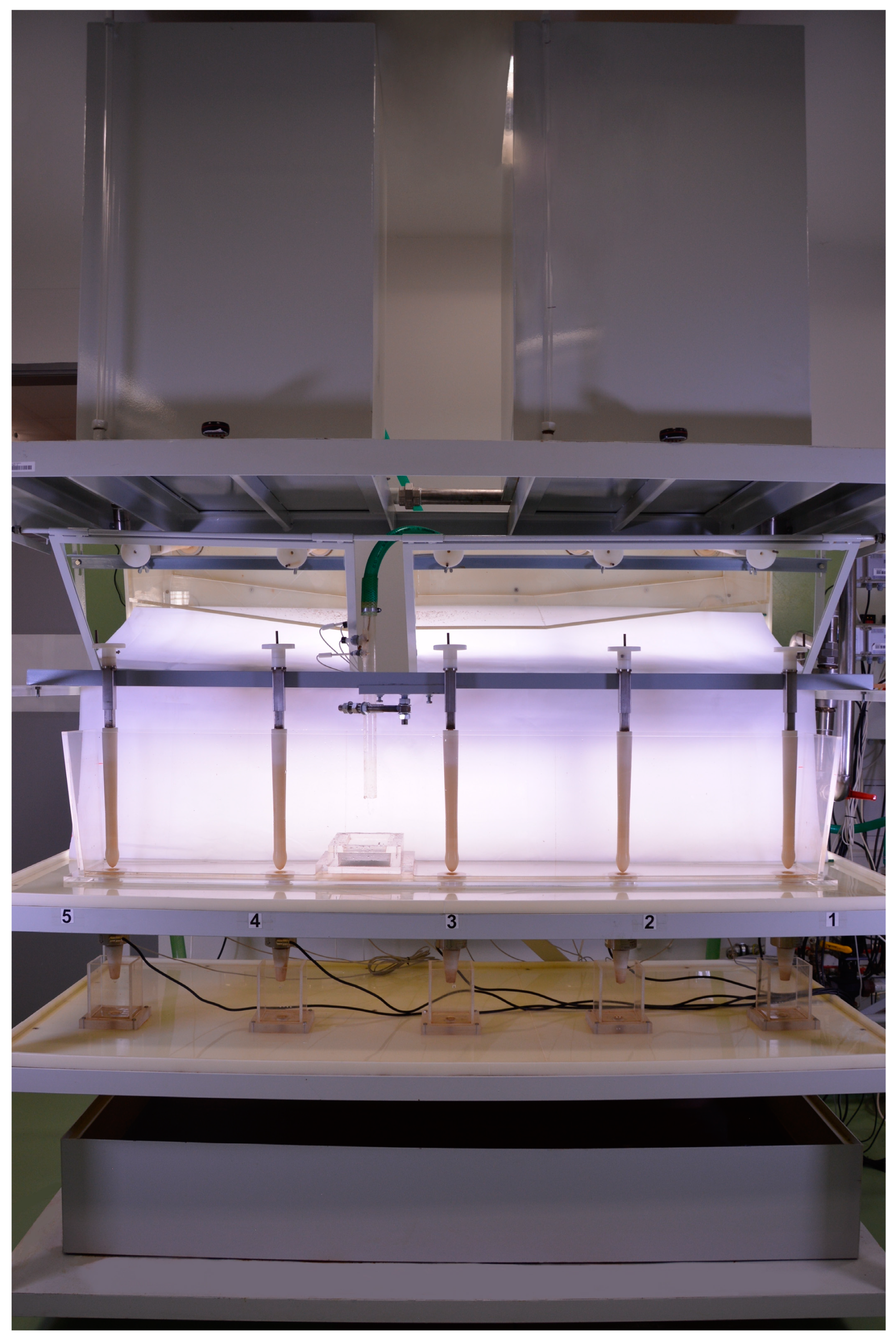
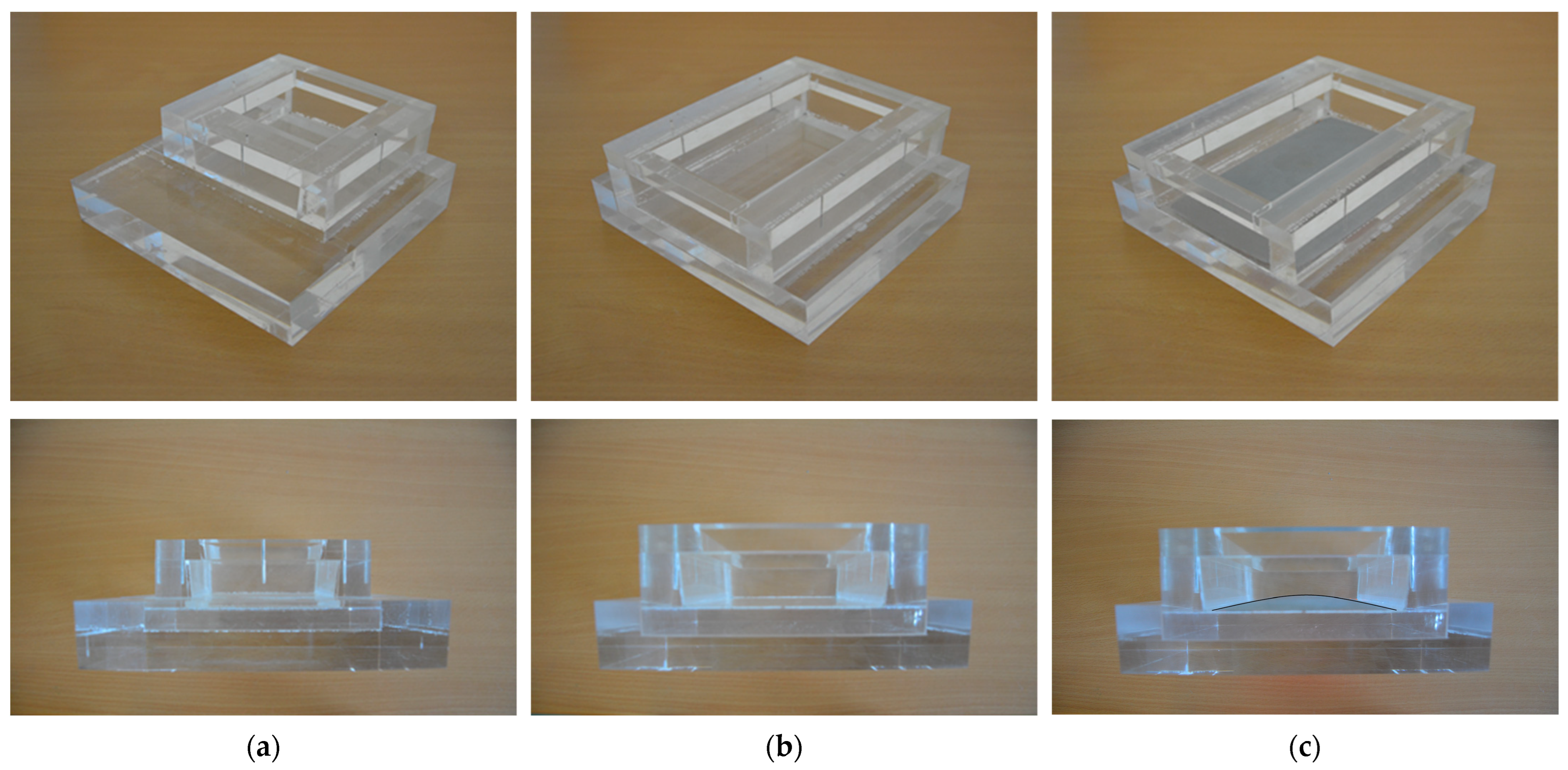
2.1. Experimental Conditions for Physical Modelling
- The shape of the turbulence inhibitor;
- The position of the ladle shroud in relation to the turbulence inhibitor.
- Rear position 1 (R1)—identical for all variants;
- Rear position 2 (R2)—identical for all variants;
- Center position (C)—for TI1; Rear position 3 (R3) for TI2 and TI3;
- Front position 1 (F1)—for TI1; identical to Center position (C) for the TI2 and TI3.
2.2. Experimental Conditions for Numerical Modelling
3. Results and Discussion
3.1. Evaluation Methodology of the Physical Experiments
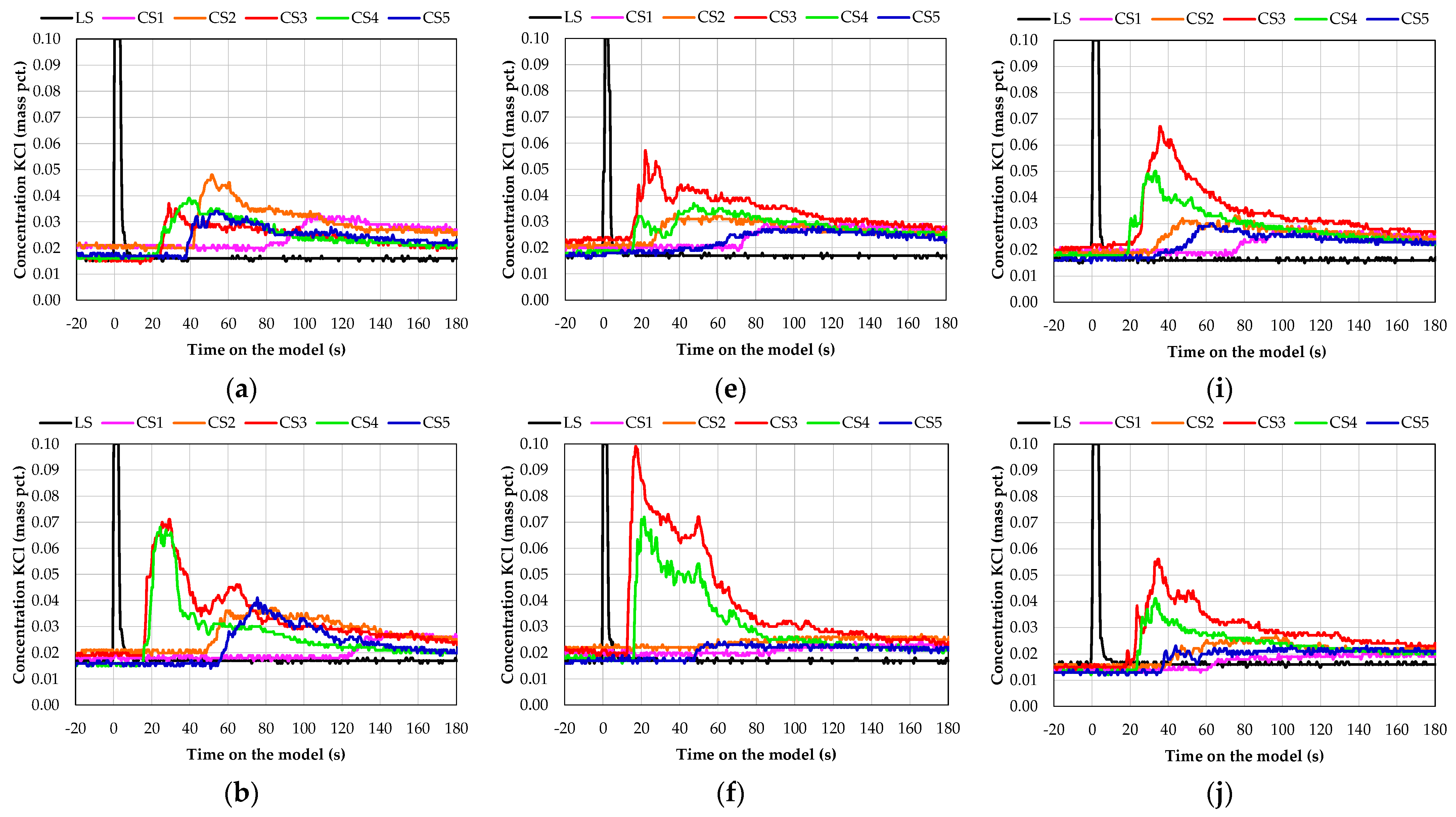
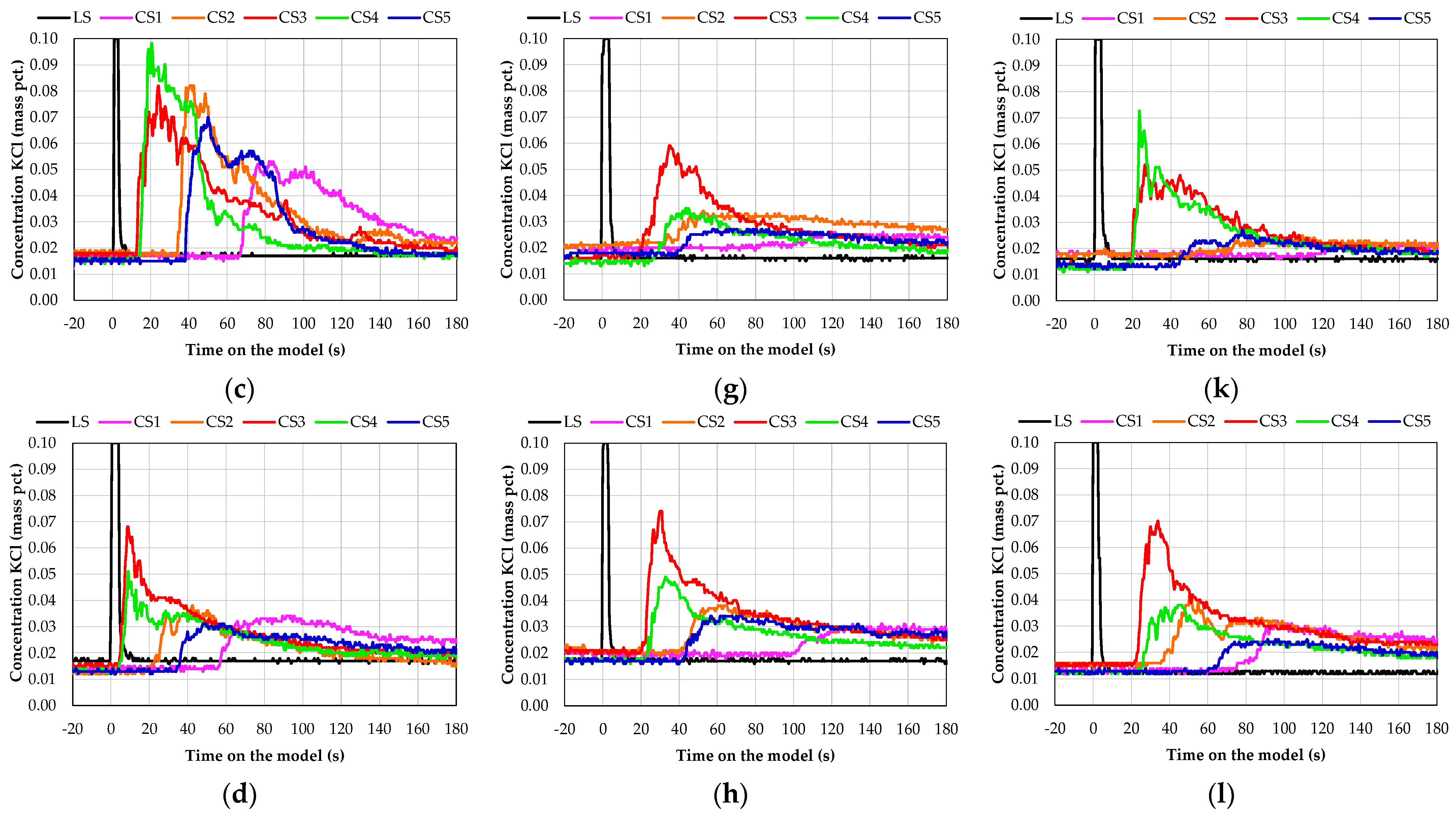
3.2. Evaluation of the Flow Characteristics from the Physical Modelling
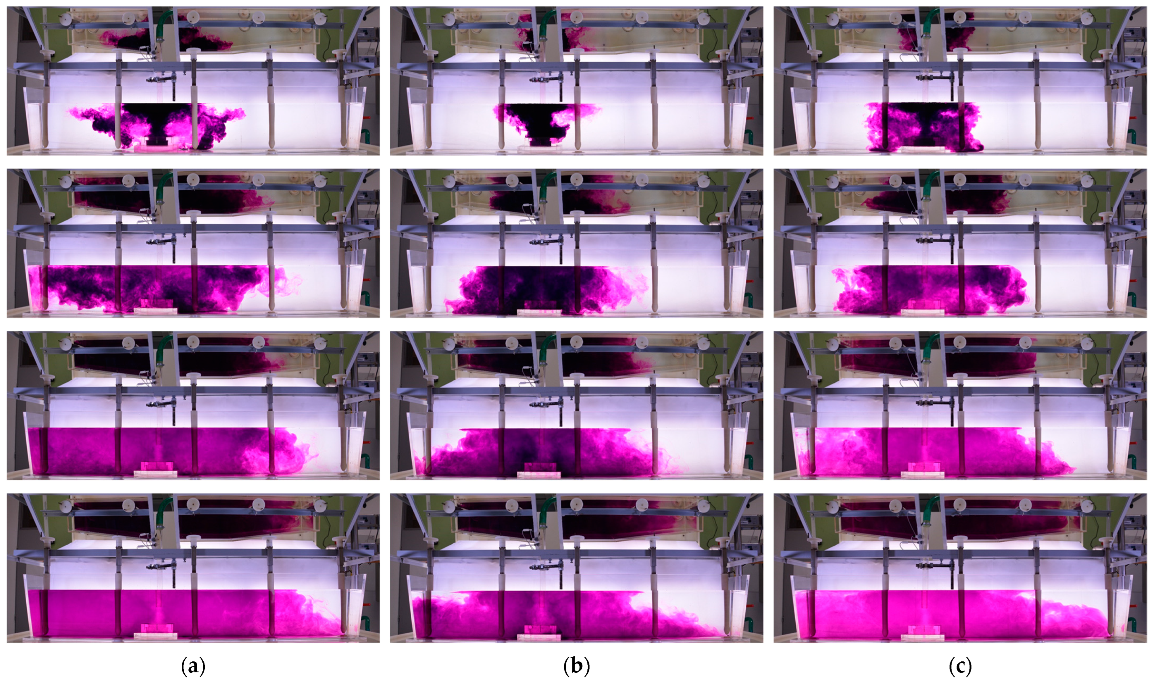
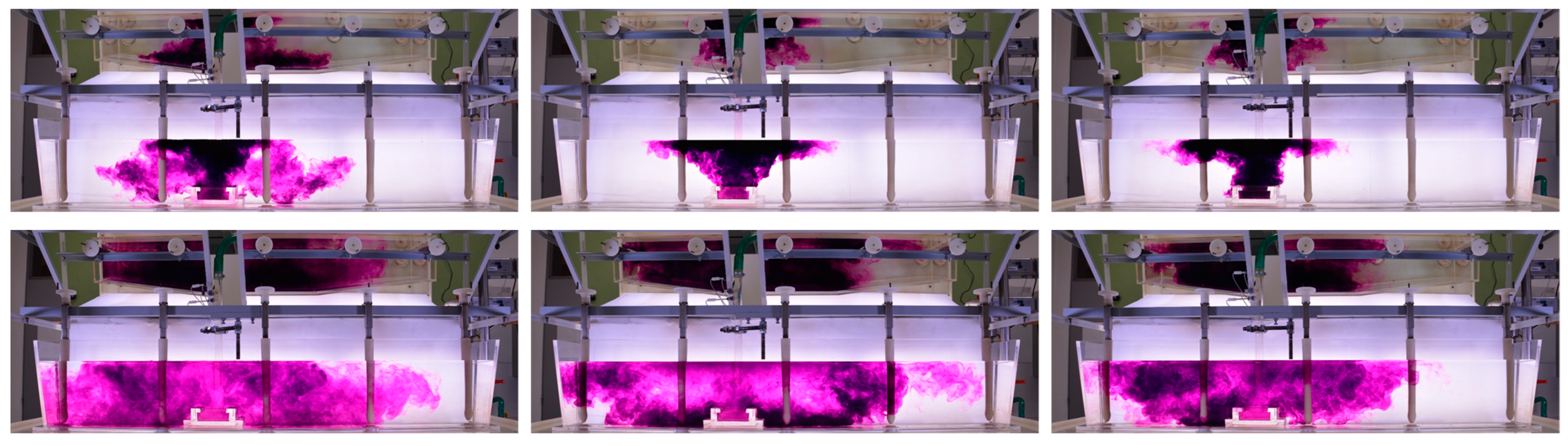
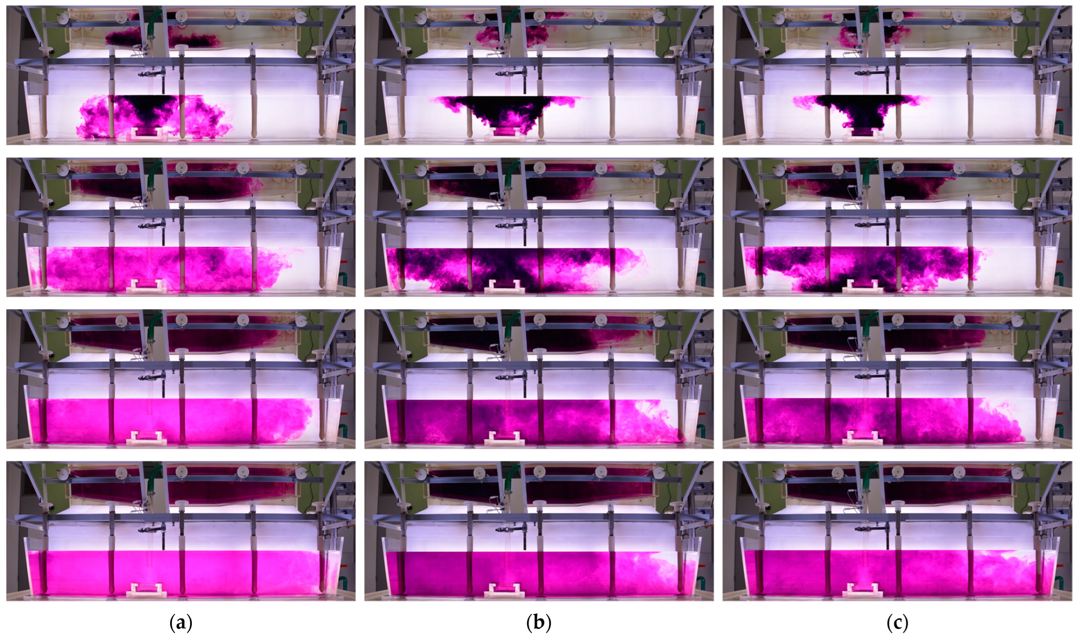
3.3. Optical Recording of the Flow Characteristics Inside the Tundish Model
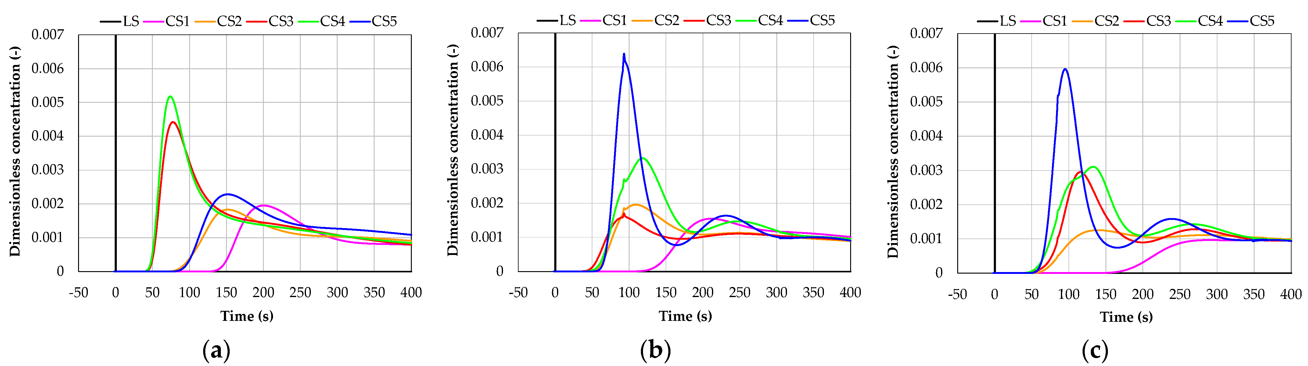
3.4. Evaluation of the Flow Characteristics in the Numerical Simulations
3.5. Comparison of the Results of the Physical Experiments and Numerical Simulations
4. Conclusions
Author Contributions
Funding
Data Availability Statement
Acknowledgments
Conflicts of Interest
References
- Louhenkilpi, S. Treatise on Process Metallurgy. In Continuous Casting of Steel; Elsevier: Amsterdam, The Netherlands, 2014; Volume 3, pp. 373–434. [Google Scholar]
- Michalek, K. Využití Fyzikálního a Numerického Modelování pro Optimalizaci Metalurgických Procesů; VŠB—Technická Univerzita Ostrava: Ostrava, Czech Republic, 2001; p. 125. (In Czech) [Google Scholar]
- Sahai, Y. Metallurgical and Materials Transactions B. In Tundish Technology for Casting Clean Steel: A Review; Springer: New York City, NY, USA, 2016; Volume 47, pp. 2095–2106. [Google Scholar]
- Huang, W.; Chang, S.; Zou, Z.; Shao, L.; Qu, Y.; Li, B. Modeling of Flow Behaviors in a Swirling Flow Tundish for the Deep Cleaning of Molten Steel. Steel Res. Int. 2021, 92, 2100012. [Google Scholar] [CrossRef]
- Delgado Ramirez, O.S.; Torres-Alonso, E.; Ramos Banderas, J.A.; Arreola, S.A.; Hernandez Bocanegra, C.A.; Tellez Martinez, J.S. Thermal and Fluid Dynamic Optimization of a Five Strand Asymmetric Delta Shaped Billet Caster Tundish. Steel Res. Int. 2018, 89, 1700428. [Google Scholar] [CrossRef]
- Zhang, B.; Liu, F.; Zhu, R.; Zhu, J. Effects of Multiple-Hole Baffle Arrangements on Flow Fields in a Five-Strand Asymmetric Tundish. Materials 2020, 13, 5129. [Google Scholar] [CrossRef] [PubMed]
- Yadav, J.N.; Singh, N.P. Experimental and Simulation Analysis of Physical Water Model through Tracer Injection under Various Baffles and Turbulence Inhibitor Conditions for Developing the Fluid Flow Parameters and Inclusion Removal Rates in Tundish. Biointerface Res. Appl. Chem. 2022, 12, 6361–6381. [Google Scholar]
- Gupta, V.K.; Jha, P.K.; Jain, P.K. Modeling of Wall Shear Stress Induced Inclusion Transport and Removal in Multi-Strand Tundish. ISIJ Int. 2021, 61, 2445–2456. [Google Scholar] [CrossRef]
- Morales, R.D.; Guarneros, J.; Najera-Bastida, A.; Rodriguez, J. Control of Two-Phase Flows during Startup Operations of Casting Sequences in a Billet Tundish. JOM 2018, 70, 2103–2108. [Google Scholar] [CrossRef]
- Morales, R.D.; Guarneros, J.; Chattopadhyay, K.; Najera-Bastida, A.; Rodriguez, J. Fluid Flow Control in a Billet Tundish during Steel Filling Operation. Metals 2019, 9, 394. [Google Scholar] [CrossRef]
- Ling, H.; Xu, R.; Wang, H.; Chang, L.; Qiu, S. Multiphase Flow Behavior in a Single-Strand Continuous Casting. ISIJ Int. 2020, 60, 499–508. [Google Scholar] [CrossRef]
- Xu, R.; Ling, H.; Wang, H.; Chang, L.; Qiu, S. Investigation on the control of multiphase flow behavior in a continuous casting tundish during ladle change. Metall. Res. Technol. 2020, 117, 619. [Google Scholar] [CrossRef]
- Jin, Y.; Dong, X.; Yang, F.; Cheng, C.; Li, Y.; Wang, W. Removal Mechanism of Microscale Non-Metallic Inclusions in a Tundish with Multi-Hole-Double-Baffles. Metals 2018, 8, 611. [Google Scholar] [CrossRef]
- Bartosiewicz, M.; Cwudziński, A. Influence of Multi-Hole Filter Modification on the Flow Hydrodynamic Structure and Refining Process of Liquid Steel in the One-Strand Tundish. Arch. Metall. Mater. 2019, 64, 71–78. [Google Scholar] [CrossRef]
- Wang, Q.; Liu, Y.; Huang, A.; Yan, W.; Gu, H.; Li, G. CFD Investigation of Effect of Multi-hole Ceramic Filter on Inclusion Removal in a Two-Strand Tundish. Met. Mater. Trans. B 2020, 51, 276–292. [Google Scholar] [CrossRef]
- Wang, Q.; Tan, C.; Huang, A.; Yan, W.; Gu, H.; He, Z.; Li, G. Numerical Simulation on Refractory Wear and Inclusion Formation in Continuous Casting Tundish. Met. Mater. Trans. B 2021, 52, 1344–1356. [Google Scholar] [CrossRef]
- Liu, C.; Xiao, A.; He, Z.; Yan, W.; Li, G.; Wang, Q. Numerical Investigation on Motion and Removal of Inclusions in Continuous Casting Tundish with Multiorifice Filter. Steel Res. Int. 2022, 93, 2100818. [Google Scholar] [CrossRef]
- Sheng, D.-Y. Mean Age Theory in Continuous Casting Tundish. Met. Mater. Trans. B 2022, 53, 2735–2752. [Google Scholar] [CrossRef]
- Sheng, D.-Y.; Chen, D. Comparison of Fluid Flow and Temperature Distribution in a Single-Strand Tundish with Different Flow Control Devices. Metals 2021, 11, 796. [Google Scholar] [CrossRef]
- Michalek, K.; Gryc, K.; Tkadlečková, M.M.; Bocek, D. Model Study of Tundish Steel Intermixing and Operational Verification. Arch. Metall. Mater. 2012, 57, 291–296. [Google Scholar] [CrossRef]
- Cwudziński, A. Numerical and Physical Modeling of Liquid Steel Flow Structure for One Strand Tundish with Modern System of Argon Injection. Steel Res. Int. 2017, 88, 1600484. [Google Scholar] [CrossRef]
- Cwudziński, A. Mathematical Simulation and Water Modelling of Liquid Steel Interaction with an Argon Bubble Curtain in a One-Strand Continuous Casting Tundish. J. S. Afr. Inst. Min. Metall. 2018, 118, 545–554. [Google Scholar] [CrossRef]
- Walek, J.; Michalek, K.; Tkadlečková, M.; Saternus, M. Modelling of Technological Parameters of Aluminium Melt Refining in the Ladle by Blowing of Inert Gas through the Rotating Impeller. Metals 2021, 11, 284. [Google Scholar] [CrossRef]
- Mazumdar, D.; Evans, J.W. Modeling of Steelmaking Processes; CRC Press, Taylor & Francis Group: Boca Raton, FL, USA, 2010; p. 463. [Google Scholar]
- Tkadlečková, M.; Walek, J.; Michalek, K.; Huczala, T. Numerical Analysis of RTD Curves and Inclusions Removal in a Multi-Strand Asymmetric Tundish with Different Configuration of Impact Pad. Metals 2020, 10, 849. [Google Scholar] [CrossRef]
- Nastac, L.; Pericleous, K.; Sabau, A.S.; Zhang, L.; Thomas, B.G. CFD Modeling and Simulation in Materials Processing 2018; The Minerals, Metals & Materials Series; Springer: Cham, Switzerland, 2018; p. 241. [Google Scholar]
- Zhang, J.; Yang, S.; Li, J.; Tang, H.; Jiang, Z. The Effect of a Dissipative Ladle Shroud on Mixing in Tundish: Mathematical and Experimental Modelling. High Temp. Mater. Proc. 2017, 37, 25–32. [Google Scholar] [CrossRef]
- Harnsihacacha, A.; Piyapaneekoon, A.; Kowitwarangkul, P. Physical water model and CFD studies of fluid flow in a single strand tundish. Mater. Today Proc. 2018, 5, 9220–9228. [Google Scholar] [CrossRef]
- Lopez-Ramirez, S.; Barreto, J.d.J.; Palafox-Ramos, J.; Morales, R.D.; Zacharias, D. Modelling Study of the Influence of Turbulence Inhibitors on the Molten Steel Flow, Tracer Dispersion, and Inclusion Trajectories in Tundishes. Met. Mater. Trans. B 2001, 32, 615–627. [Google Scholar] [CrossRef]
- Morales, R.D.; Lopez-Ramirez, S.; Palafox-Ramos, J.; Zacharias, D. Mathematical simulation of effects of flow control devices and buoyancy forces on molten steel flow and evolution of output temperatures in tundish. Ironmak. Steelmak. 2001, 28, 33–43. [Google Scholar] [CrossRef]


| Symbol | Parameter | Prototype | Model |
|---|---|---|---|
| V | Volume of the bath in the tundish [m3] | 4.64 | 37.12 × 10⁻³ |
| m | Weight of the bath in the tundish [kg] | 32,480 | 37.04 |
| Tk | Average temperature of the bath [K] | 1520 + 273 | 20 + 273 |
| k | Average density of the bath [kg·m−3] | 7000 | 998 |
| k | Kinematic viscosity of the bath [m2·s−1] | 0.913 × 10⁻⁶ | 1.02 × 10⁻⁶ |
| g | Gravitational acceleration [m·s−2] | 9.81 | 9.81 |
| pv | Pressure above the bath surface [kg·m−1·s−2] | 98.06 × 10³ | 98.06 × 10³ |
| L1 | Internal length of the tundish at the plane of the bottom [m] | 6.387 | 1.597 |
| L2 | Distance between SEN [m] | 1.5 | 0.375 |
| D1 | Inner diameter of the ladle shroud [m] | 0.085 | 0.021 |
| H1 | Bath height appropriate to weight m [m] | 0.925 | 0.231 |
| H2 | Distance of the ladle shroud orifice from the bottom of the TI [m] | 0.525 | 0.131 |
| Qm, k | Mass flow rate of the bath to the tundish [kg·min−1] | 2779 | 12.39 |
| Qv, k | Volumetric flow rate of the bath to the tundish [l·min−1] | 397 | 12.41 |
| Qv, kr | Volumetric flow rate on the each SEN [l·min−1] | 79.4 | 2.48 |
| Temperature (K) | Density (kg·m−3) | Specific Heat (J·kg−1·K−1) | Thermal Conductivity (W·m−1·K−1) | Viscosity (kg·m−1·s−1) |
|---|---|---|---|---|
| 1793 | 6970 | 821 | 35 | 0.0055 |
| 1773 | 6985 | 813 | 35 | 0.0057 |
| 1753 | 7001 | 805 | 35 | 0.0059 |
| Parameter | Value |
|---|---|
| Mass flow rate of the steel through the ladle shroud [kg·s−1] | 46.32 |
| Casting temperature [K] | 1773 |
| Turbulence intensity [%] | 10 |
| Hydraulic diameter [m] | 0.085 |
| Heat flux of the free surface [W·m−2] | 15,000 |
| Heat flux through the walls of the tundish [W·m−2] | 2500 |
| Gravity [m·s−2] | −9.81 |
| Operating pressure [Pa] | 101,325 |
| Operating temperature [K] | 1773 |
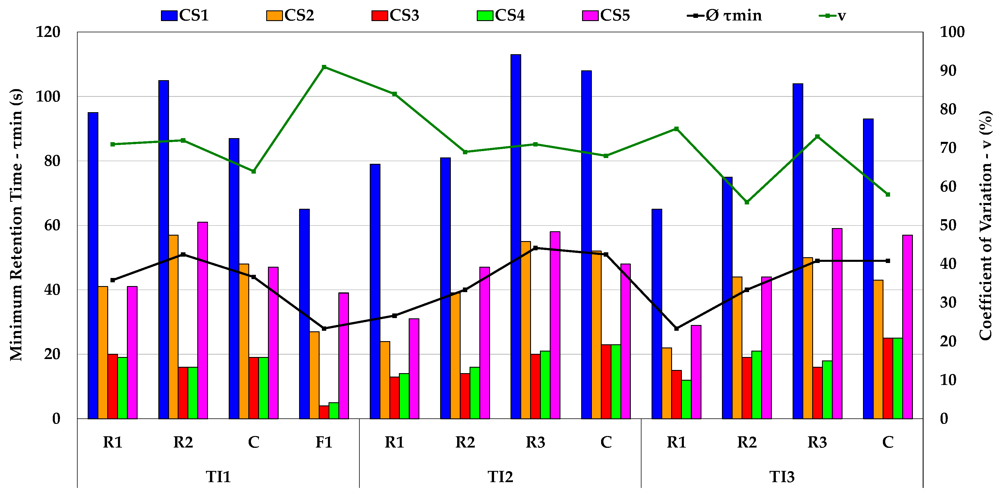
| Variant | CS1 | CS2 | CS3 | CS4 | CS5 | Ø | v | Vm/V | Vp/V | Vd/V | Vp/Vd |
|---|---|---|---|---|---|---|---|---|---|---|---|
| τmin (s) | τmin (s) | τmin (s) | τmin (s) | τmin (s) | τmin (s) | (%) | (%) | (%) | (%) | (-) | |
| TI1-R1 | 95 | 41 | 20 | 19 | 41 | 43 | 71 | 57 | 25 | 18 | 1.34 |
| TI1-R2 | 105 | 57 | 16 | 16 | 61 | 51 | 72 | 52 | 31 | 17 | 1.81 |
| TI1-C | 87 | 48 | 19 | 19 | 47 | 44 | 64 | 43 | 24 | 33 | 0.74 |
| TI1-F1 | 65 | 27 | 4 | 5 | 39 | 28 | 91 | 54 | 16 | 30 | 0.51 |
| TI2-R1 | 79 | 24 | 13 | 14 | 31 | 32 | 84 | 65 | 18 | 17 | 1.05 |
| TI2-R2 | 81 | 39 | 14 | 16 | 47 | 40 | 69 | 55 | 22 | 23 | 0.98 |
| TI2-R3 | 113 | 55 | 20 | 21 | 58 | 53 | 71 | 55 | 31 | 14 | 2.16 |
| TI2-C | 108 | 52 | 23 | 23 | 48 | 51 | 68 | 58 | 28 | 14 | 1.97 |
| TI3-R1 | 65 | 22 | 15 | 12 | 29 | 28 | 75 | 56 | 16 | 28 | 0.56 |
| TI3-R2 | 75 | 44 | 19 | 21 | 44 | 40 | 56 | 58 | 23 | 19 | 1.20 |
| TI3-R3 | 104 | 50 | 16 | 18 | 59 | 49 | 73 | 53 | 28 | 20 | 1.39 |
| TI3-C | 93 | 43 | 25 | 25 | 57 | 49 | 58 | 59 | 27 | 14 | 1.99 |
| Variant | CS1 τmin (s) | CS2 τmin (s) | CS3 τmin (s) | CS4 τmin (s) | CS5 τmin (s) | Ø τmin (s) | v (%) |
|---|---|---|---|---|---|---|---|
| TI1-C | 135 | 79 | 45 | 44 | 85 | 78 | 48 |
| TI2-C | 120 | 54 | 44 | 45 | 59 | 64 | 49 |
| TI3-C | 155 | 60 | 49 | 46 | 55 | 73 | 63 |
| Variant | Conditions | CS1 τmin (s) | CS2 τmin (s) | CS3 τmin (s) | CS4 τmin (s) | CS5 τmin (s) | Ø τmin (s) |
|---|---|---|---|---|---|---|---|
| TI1-C | Model | 87 | 48 | 19 | 19 | 47 | 44 |
| Prototype | 174 | 96 | 38 | 38 | 94 | 88 | |
| NS | 135 | 79 | 45 | 44 | 85 | 78 | |
| TI2-C | Model | 108 | 52 | 23 | 23 | 48 | 51 |
| Prototype | 216 | 104 | 46 | 46 | 96 | 102 | |
| NS | 120 | 54 | 44 | 45 | 59 | 64 | |
| TI3-C | Model | 93 | 43 | 25 | 25 | 57 | 49 |
| Prototype | 186 | 86 | 50 | 50 | 114 | 98 | |
| NS | 155 | 60 | 49 | 46 | 55 | 73 |
Disclaimer/Publisher’s Note: The statements, opinions and data contained in all publications are solely those of the individual author(s) and contributor(s) and not of MDPI and/or the editor(s). MDPI and/or the editor(s) disclaim responsibility for any injury to people or property resulting from any ideas, methods, instructions or products referred to in the content. |
© 2023 by the authors. Licensee MDPI, Basel, Switzerland. This article is an open access article distributed under the terms and conditions of the Creative Commons Attribution (CC BY) license (https://creativecommons.org/licenses/by/4.0/).
Share and Cite
Walek, J.; Tkadlečková, M.; Velička, M.; Machů, M.; Cupek, J.; Huczala, T.; Cibulka, J.; Růžička, J.; Michalek, K. Physical Experiments and Numerical Simulations of the Influence of Turbulence Inhibitors and the Position of Ladle Shroud on the Steel Flow in an Asymmetric Five-Strand Tundish. Metals 2023, 13, 1821. https://doi.org/10.3390/met13111821
Walek J, Tkadlečková M, Velička M, Machů M, Cupek J, Huczala T, Cibulka J, Růžička J, Michalek K. Physical Experiments and Numerical Simulations of the Influence of Turbulence Inhibitors and the Position of Ladle Shroud on the Steel Flow in an Asymmetric Five-Strand Tundish. Metals. 2023; 13(11):1821. https://doi.org/10.3390/met13111821
Chicago/Turabian StyleWalek, Josef, Markéta Tkadlečková, Marek Velička, Mario Machů, Jiří Cupek, Tomáš Huczala, Jiří Cibulka, Jan Růžička, and Karel Michalek. 2023. "Physical Experiments and Numerical Simulations of the Influence of Turbulence Inhibitors and the Position of Ladle Shroud on the Steel Flow in an Asymmetric Five-Strand Tundish" Metals 13, no. 11: 1821. https://doi.org/10.3390/met13111821