
Optimization of Laser Powder Bed Fusion Process for Forming Porous Ta Scaffold
by
Lin Gao
1,2,*,
Yikai Wang
1,2,
Xiao Qin
1,2,
Naixin Lv
1,2,
Zhiqiang Tong
1,2,
Changning Sun
1,2 and
Dichen Li
1,2 1
State Key Laboratory for Manufacturing System Engineering, School of Mechanical Engineering, Xi’an Jiaotong University, Xi’an 710054, China
2
National Medical Products Administration (NMPA), Key Laboratory for Research and Evaluation of Additive Manufacturing Medical Devices, Xi’an Jiaotong University, Xi’an 710054, China
*
Author to whom correspondence should be addressed.
Metals 2023, 13(10), 1764; https://doi.org/10.3390/met13101764
Submission received: 14 August 2023
/
Revised: 15 September 2023
/
Accepted: 10 October 2023
/
Published: 17 October 2023
Abstract
:To improve the performance of porous tantalum (Ta) manufactured by laser powder bed fusion (L-PBF) and meet its application requirements in medicine, the authors of this paper studied the influence of L-PBF process parameters on the strut surface morphology and mechanical performance. It was found that the powder layer thickness had a significant influence on the microstructure and mechanical properties based on statistical analysis. We proposed optimal process parameters of laser power of 150 W, scanning speed of 270 mm/s, thickness of 0.05 mm, and scanning spacing of 0.07 mm. After parameter optimization, we successfully obtained Ta samples with an elastic modulus of 1.352 ± 0.007 GPa and yield strength of 53.217 ± 0.114 MPa. The results show that the elastic modulus and yield strength of porous Ta samples with a porosity of 80% under the optimal process parameters are significantly superior to previous studies. The porous Ta scaffolds with higher mechanical properties fabricated with the optimized process parameters of L-PBF have significant value for applications in medicine.
1. Introduction
Tantalum (Ta) and its compounds have been widely applied in aerospace, electronics, and especially medical fields due to their excellent performance, including high hardness, toughness, ductility, and corrosion resistance [1,2,3]. Ta is commonly recognized as a promising implantable biomaterial for its biocompatibility, non-cytotoxicity, and suitability for the attachment and growth of osteoblasts [1,4]. However, solid Ta would cause a stress-shielding effect after implantation for its much higher elastic modulus (186 GPa), compared to that of human cortical bone (12–18 GPa) and cancellous bone (0.1–1.5 GPa), resulting in bone resorption and aseptic loosening in clinical applications [5,6]. Porous Ta can significantly decrease the elastic modulus with a microstructure similar to human cancellous bone. Furthermore, previous studies have confirmed that porous Ta scaffolds have superior vascularization, osteogenesis, osteointegration, and osteoconductivity, in contrast to the porous Ti6Al4V scaffolds commonly used [7,8,9,10,11]. The overall excellent performance of porous Ta has made it a hotspot of research and development for orthopedic implants, such as intervertebral fusion cages [12], artificial joint prostheses [13,14], and dental implants [6].
However, it is challenging to fabricate porous Ta scaffolds using conventional forming techniques with patient-specific and anatomy-matching geometry for extensive bone defects or deformities, and complex interconnected porous micro-architectures. Furthermore, the high melting point (2996 °C) and affinity with carbon, hydrogen, and oxygen of Ta increase the difficulty of its manufacturing techniques. As a novel additive manufacturing (AM) approach, laser powder bed fusion (L-PBF), also known as selective laser melting (SLM), can fulfill all the above strict requirements by melting powder according to an arranged path directly from CAD models layer by layer using computer-controlled micro-scale laser spots. The L-PBF technique has advantages, including rapid production without geometric constraint, high forming accuracy, controllable relative density, and material utilization, in contrast to traditional manufacturing techniques [15,16,17], providing an advanced manufacturing technique for porous tantalum applications in orthopedic surgery. For example, Wauthle R et al. fabricated a porous tantalum implant by SLM with a dodecahedron structure and found it had higher fatigue strength and toughness than Ti6Al4V [1]. These studies indicated that porous Ta scaffolds have promising mechanical properties and biological function [1,18,19]. As a basis for practical applications, some studies have investigated the process of manufacturing pure tantalum with SLM. Ghouse S et al. showed that the fatigue strength of a pure Ta scaffold was highly correlated to the laser parameters and scanning strategies [20]. Song C et al. manufactured a pure dense Ta block sample and revealed that the scanning speed had a great influence on the microstructure [21]. Livescu V et al. explored the influence of the scanning speed, layer thickness, and other parameters on the compression performance and grain orientation of pure Ta and manufactured a dense pure tantalum sample with excellent compression performance [22]. Most studies have focused on the relationship between the SLM process parameters and the mechanical properties of dense Ta. Since the structures of porous Ta and dense Ta are different, the effect of L-PBF printing on porous tantalum is unpredictable. The forming quality of porous struts and the junction between struts is especially important for the mechanical properties of porous tantalum. However, there are few studies on the effects of the process parameters on the microstructure and mechanical properties of porous Ta scaffolds, which could lead to challenges in tantalum applications.
The purpose of this study was to systematically explore the effect of the L-PBF process parameters (laser power, scanning speed, powder layer thickness, and scanning distance) on the microstructure and compression performance of porous Ta scaffolds with 80% porosity (60–80% approaches the natural bone elasticity modulus) based on a diamond structure statistically [23]. This study can provide a reference for L-PBF process parameter optimization to obtain porous Ta scaffolds with a higher relative density and better mechanical properties.
2. Material and Methods
2.1. Microstructure Design of Porous Ta Scaffold
The diamond unit cell structure has excellent osteogenic effects and mechanical properties [1] and has been widely used in the design and fabrication of orthopedic implants. Here, a diamond cell structure was established by SolidWorks software (Dassault, France) with a porosity of 80%, a cell side length of 3 mm, and a strut diameter of 656 μm (Figure 1a). In order to minimize the size effect on the mechanical properties of the cell structure, we repeated the cell structure 4 times in every direction to form a block sample of 12 × 12 × 12 mm3 (Figure 1b,c).
2.2. Materials
Spherical Ta powder (Suzhou Yaoyi New Material Technology Co, Ltd., Suzhou, China) with a purity of 99.99%, and a particle size ranging from 15 to 53 μm was used in our study. The chemical composition is shown in Table 1. Scanning electron microscopy (SEM, Zeiss Gemini 500, Jena, Germany) was used to observe the morphology of the powder particles (Figure 2a,b). The particle size was approximately normally distributed with D10 = 23.738 μm, D50 = 33.801 μm, D90 = 48.121 μm (Figure 2c). It took 5.91 s for 50 g of powder to naturally flow through a 2.5 mm hole to indicate good fluidity, which was conducive for uniform spreading of the powder during L-PBF forming.
2.3. L-PBF Equipment
The experimental equipment used in this study was a L-PBF machine self-developed by Xi’an Jiaotong University. The apparatus is equipped with a 500 W fiber laser (YLR-500-WC, IPJ, Germany) 45 µm in diameter and 1070.94 nm in wavelength for refractory metal materials fabrication. The maximum forming size is 800 mm (height) × 150 mm (diameter). During the experiment, the forming chamber was filled with high-purity argon (99.96%) as the protective gas preventing oxidation of the material at a high temperature. In order to ensure the dryness of the powder, the powder material was heated up to 200 °C within 1 h, kept for 3 h, and cooled to room temperature in a drying oven before the experiment [24]. A titanium alloy substrate was selected with a thickness of 30 mm for the experiment, and its surface was cleaned with alcohol after processing by grinding wheel.
2.4. L-PBF Process of Porous Ta Scaffolds
Concerning the L-PBF processing parameters affecting the forming quality, we selected laser power (P), scanning speed (v), powder layer thickness (t), and scanning distance (h) as variables in this study. The laser power was set to 120 (kA1), 150 (kA2), and 180 W (kA3), because too low laser power would lead to incompletely melted powder, whereas too high power would produce an over-melting phenomenon, resulting in some defects, such as pores. The scanning speeds were 270 mm/s (kB1), 300 mm/s (kB2) and 330 mm/s (kB3), owing to the fact that the effects of a high scanning speed are similar to that of low laser power, and vice versa. The powder layer thickness was 0.03 mm (kC1), 0.04 mm (kC2), and 0.05 mm (kC3), due to the limitation of the powder particle size and the bonding effect between the layers. The scanning spacing varied from 0.05 mm (kD1), 0.06 mm (kD2), to 0.07 mm (kD3), because too small spacing would generate over-melting, and too large spacing would affect single-pass lap joints, and even the forming quality of each layer. Above all, the orthogonal scanning strategy was adopted, as shown Table 2. The porous structure was prepared with different process parameters, and a total of 36 samples were fabricated, with 4 samples in each group. The samples were cut off from the substrate by wire cutting and soaked in an aqueous ethanol after sandblasting. The residual powder in the samples was removed by ultrasonic cleaning for 1 h. The effects of different manufacturing parameters on the micro-morphology and mechanical properties of the porous Ta samples were analyzed.
2.5. Porosity Measurement and Porous Structure Characterization
The microstructure characteristics of porous Ta scaffold samples were visualized using a high-resolution scanning electron microscope (Gemini500, ZEISS Microscopy, Jena, Germany). The strut diameters were evaluated based on the SEM images by Image J software. Ten different positions in each sample were selected for measurements, and the average strut diameters were calculated.
The overall porosity of the samples was determined by a dry weighing method under normal atmosphere conditions. The dry weight of samples was measured using an electronic densimeter with a sensitivity of 0.01 mg (XS105DU, Mettler-Toledo, Zurich, Switzerland) at room temperature (25 °C). The dimension was measured by digital Vernier calipers with a 0.01 mm accuracy (DL91150, Deli Group Co., Ltd., Ningbo, China), and represented by the average of three points on each specimen to calculate the volumes. The actual density ρa was acquired by dividing the weight by the volume of each specimen. The relative density was calculated by dividing the actual density ρa by the theoretical density ρs (16.65 g/cm3) of pure Ta. The porosity of the scaffolds was obtained as follows [25]:
Porosity (%) = (1 − ρa/ρs) × 100%
2.6. Compressive Mechanical Property Test
The mechanical properties of the L-PBF-fabricated porous Ta scaffolds were measured by uniaxial quasi-static compressive testing at room temperature (25 °C). Compressive tests were performed according to ISO 13314:2011 [26] (Mechanical testing of metals—Ductility testing—Compression test for porous and cellular metals) with a mechanical testing system (CMT4304, Max. 35 kN, Xian Letry Testing Machinese Co., Ltd., Xi’an, China) along the forming and horizontal directions respectively, as shown in Figure 1c. Four samples were measured in each group. Each specimen was compressed to failure with a constant deformation rate of 1 mm/min to obtain the stress–strain curves. The elastic modulus E was calculated as the gradient of the elastic deformation line at the beginning of the compressive stress–strain curves. The compressive 0.2% offset stress from the stress–strain curves represents the yield strength.
2.7. Statistical Analysis Method
Range analysis was applied to explore the effects of controllable factors on the strut diameters of the porous Ta scaffold samples. Moreover, analysis of variance (ANOVA) was used to discuss the important factors on the strut diameters of the samples formed by L-PBF, and also to determine which was most significant under investigation. An orthogonal experiment design is an experimental design technique based on multi-factor experimental design, which can obtain more accurate and reliable conclusions with fewer experimental repetitions [27]. The criterion of influence significance of the controllable factors in the orthogonal experiment is as follows: if Fj ≥ F0.01(2,2), it indicates that the influence of this factor is particularly significant with the mark **; if F0.05(2,2) ≤ Fj ≤ F0.01(2,2), this factor has a significant influence with *; if F0.1(2,2) ≤ Fj ≤ F0.05(2,2), this factor has a significant influence with (*), where Fj is the statistical test value of factor j. F0.01(2,2) is the critical value of Row 2 and Column 2 on the F distribution table with a reliability of 0.01. F0.1(2,2) is the critical value of Row 2 and Column 2 on the F distribution table with a reliability of 0.1. F0.05(2,2) is the critical value of Row 2 and Column 2 on the F distribution table with a reliability of 0.05 [28,29].
3. Results and Discussions
3.1. Microstructure Characterization
Figure 3 shows macroscopic photographs of the Ta scaffolds with 80% porosities fabricated by L-PBF. The average macroscopic geometry size (12.19 mm × 12.21 mm × 12.13 mm) was slightly larger than that of the designed models (12 mm × 12 mm × 12 mm). Figure 4 shows the SEM microstructure images of the porous Ta scaffolds, indicating that these struts were tightly connected and arranged neatly, and the junctions of the struts were smooth. The porosities and strut diameters of the samples manufactured with different process parameters can be measured from SEM images (Table 3). The average porosities of the samples in nine groups were within a 3.1% deviation from the designed value. The strut diameters of the samples were generally larger than that of the designed model due to the powder over-melting at the edge of the processing paths. The powder adhering to the strut surface could be partially removed after sandblasting, but some irregular areas at the joints were difficult to remove. Particularly, the strut diameters in the building direction were commonly smaller than that in the horizontal direction, probably resulting from the scanning distance and light spot size in the horizontal direction during the contour scanning. In comparison, it was only affected by the thickness of the powder layer in the building direction. The porosities were reduced with the increase in the strut diameters. In Groups 1, 5, 6, and 8, the porosities were even larger than that of the design model, although the strut diameters were larger, indicating relatively severe defects or cracks in the struts under specific processing parameters.
3.2. Compressive Mechanical Properties
Figure 5 displays photographs of the porous Ta structures with their original structure (Figure 5a) and the destructive morphology (Figure 5b) after a compression test. The failure was mainly concentrated at the strut joints at a macro-scale. Under a compressive load, the stress gradually increased at the strut joints, leading to expanding cracks, and ultimately, fracture failure of the porous structures. The fractures generally occurred at an angle of 45° to the horizontal direction, as shown in Figure 5b. Figure 6 shows the compressive stress–strain curves of the L-PBF-fabricated cubic lattice Ta scaffolds in all nine groups in the building direction and the horizontal direction, respectively. The compressive stress–strain curves of the porous Ta samples show three deformation stages: linear deformation stage, plastic deformation stage and densification stage. The calculated elastic modulus in the building direction was generally smaller larger than that in the horizontal direction due to varied strut diameters resulting from the limitations of the forming process.
Figure 7 shows a comparison of the yield strength of the porous Ta with different process parameters in two compression directions respectively. Except for Groups 1, 6, and 8, with poor forming quality, the mechanical properties of the other groups were almost not affected by the compression directions. The elastic moduli of the porous Ta structures prepared with different process parameters were from 0.408 ± 0.004 Gpa to 1.265 ± 0.006 Gpa in the building direction, and from 0.499 ± 0.007 Gpa to 1.296 ± 0.015 Gpa in the horizontal direction. The yield strengths were from 13.554 ± 0.006 Mpa to 50.322 ± 0.055 Mpa in the building direction, and from 18.447 ± 0.052 Mpa to 53.217 ± 0.11 Mpa in the horizontal direction. As observed in Figure 7, the values of E (elastic modulus) and YS (yield strength) in the Z-axis direction were larger than those in the Y-axis direction. In fact, the forming quality of the samples in the Y-axis direction was higher with a larger strut diameter. The larger size error of the struts in the horizontal direction was caused by the difference in the scanning spacing and the influence of the laser spot size during the profile scanning of the porous structures in the preparation process, while the size of the struts in the building direction was only affected by the thickness of the powder layer. Therefore, the calculated elastic modulus in the building direction was generally slightly larger than that in the horizontal direction due to varied strut diameters in the horizontal direction resulting from the limitations of the forming process. We could see the porous Ta samples from Group 4 (laser power: 150 W; scanning speed: 270 mm/s; thickness: 0.05 mm; scanning spacing: 0.07 mm) demonstrated a mechanical performance superior to the others in both the building direction (1.265 ± 0.006 Gpa) and the horizontal direction (1.296 ± 0.015 Gpa), as shown in Figure 6 and Figure 7. The Group 4 samples had larger powder layer thickness and scanning spacing compared to the other samples, due to the presence of porosities in the porous structures, and the high level of heat generated inside the melt pools during the preparation process was more easily dispersed. The results show that the samples prepared by the process parameters in Group 4 had higher forming quality and fewer defects, such as cracks.
3.3. Statistical Results on the Influence of L-PBF Parameters on the Forming Quality
3.3.1. Range Analysis Results
The range analysis results of the strut diameter, porosity, and elastic modulus with three levels of the processing parameters are shown in Table 4. By comparing the Rj value (RC > RA > RD > RB), we found that the powder layer thickness had the greatest impact on the strut diameter among the parameters, while the smallest one was the scanning speed. On the other hand, there were still some powder adhesions on the surfaces of the struts in both directions after sandblasting treatment from Figure 5. Some of the molten metal powder was bonded to the surfaces during the manufacture process, thereby affecting the strut diameters. Thus, both the range analysis and the microstructure observation revealed that the thickness of the powder layer had a significant impact on the strut diameters in the building direction. From Table 5, it can be seen the thickness of the powder layer had the greatest impact on the porosity of porous Ta (Rc = 0.0497), followed by the laser power (Ra = 0.0118), scanning spacing (Rd = 0.0086), and scanning speed (Rb = 0.0062), which is consistent with the range analysis on the strut diameters. By analyzing the range results of the elastic modulus in Table 6, it was obtained that the thickness of the powder layer had the largest impact on the elastic modulus of the porous Ta samples, while the scanning speed had the smallest. All of the range analysis results prove that the thickness of the power layer was a determining factor for the forming quality of the L-PBF-fabricated Ta scaffolds.
3.3.2. Variance Analysis Results
Furthermore, the variance analysis was conducted based on the results of range analysis to determine the factors affecting the forming quality of the porous Ta scaffolds. The variance analysis results of the strut diameter, porosity, and elastic modulus were calculated based on the orthogonal experiments in Table 7, Table 8 and Table 9, respectively. As shown in Table 7, the thickness of the powder layer had a significant impact on the strut diameter, with a contribution of 64.91%, followed by the laser power (14.14%) and the scanning spacing (11.64%). Meanwhile, the scanning speed had no significant influence on the strut diameter. These results are consistent with those of the range analysis. Thus, it is necessary to firstly control the thickness of the powder layer, followed by the laser power and the scanning spacing when optimizing the L-PBF process for porous Ta scaffolds. For the variance analysis of the porosity of porous Ta samples in Table 8, the thickness of the powder layer had the most significant impact on the porosity (88.60%), while the other processing parameters had no significant effect. The variance analysis results on the elastic modulus of porous Ta samples are shown in Table 9. The sum of the squared deviations of the laser power, scanning speed, and scanning spacing is 0.076, smaller than that of the errors (0.105). So, it was necessary to merge the other three factors to obtain new deviation values and factor contributions. We can see that the contribution of the thickness of the powder layer was as high as 89.82%, and thus, it had a significant impact on the elastic modulus of porous Ta samples. The effect of other process parameters was not significant, which is consistent with the results of the porosity variance analysis.
The relationships between the different process parameter levels and the forming quality of the porous Ta samples are shown in Figure 8. In order to decrease the error on the strut diameter and improve the porosity as designed, the laser power and scanning spacing were chosen as 180 W and 0.07 mm, respectively (Figure 8a,b). On the other hand, considering the mechanical characteristics, the thickness of powder layer was selected as 0.05, as it indicated the largest elastic modulus, and the scanning speed was 270 mm/s (Figure 8c). Thus, based on the range and variance analysis results, the L-PBF processing parameters were optimized as laser power of 180 W, scanning speed of 270 mm/s, thickness of 0.05 mm, and scanning spacing of 0.07 mm.
3.4. Porous Ta Morphology and Mechanical Properties with Optimal Process Parameters
In the orthogonal experiment, the porous Ta samples prepared by Group 4 demonstrated the best mechanical properties, with compressive elastic moduli along the building and horizontal directions of 1.265 ± 0.006 GPa and 1.296 ± 0.015 GPa, respectively. Based on the above statistical analysis results, the optimal process parameters for the preparation of porous Ta were obtained (laser power: 180 W; scanning speed: 270 mm/s; thickness: 0.05 mm; scanning spacing: 0.07 mm). The same porous structure was fabricated using the optimal process parameters, and its microstructure and mechanical properties were evaluated compared to that of the samples in Group 4. The microstructure morphology of the porous Ta samples prepared by the optimal process is shown in Figure 9. After the sandblasting treatment, the adhesion phenomenon on the surfaces of the structure were significantly improved, and the transitions at the strut joints were relatively smooth.
The performance comparison results of the porous Ta samples from Group 4 and the optimized processing group are shown in Table 10. We found that the porosities of the porous Ta were decreased from 75.11 ± 0.11% to 74.00 ± 0.13% by the optimized L-PBF processing, and the strut diameter in the horizontal direction was reduced from 0.892 ± 0.014 mm to 0.857 ± 0.009 mm after optimization. However, the strut diameter in the building direction remained almost stable. Although the strut diameter of the porous Ta samples was smaller in the horizontal direction, the elastic modulus of the porous structure in the corresponding direction had increased from 1.296 ± 0.015 GPa to 1.352 ± 0.007 GPa, indicating that the L-PBF process optimization had effectively improved the forming quality.
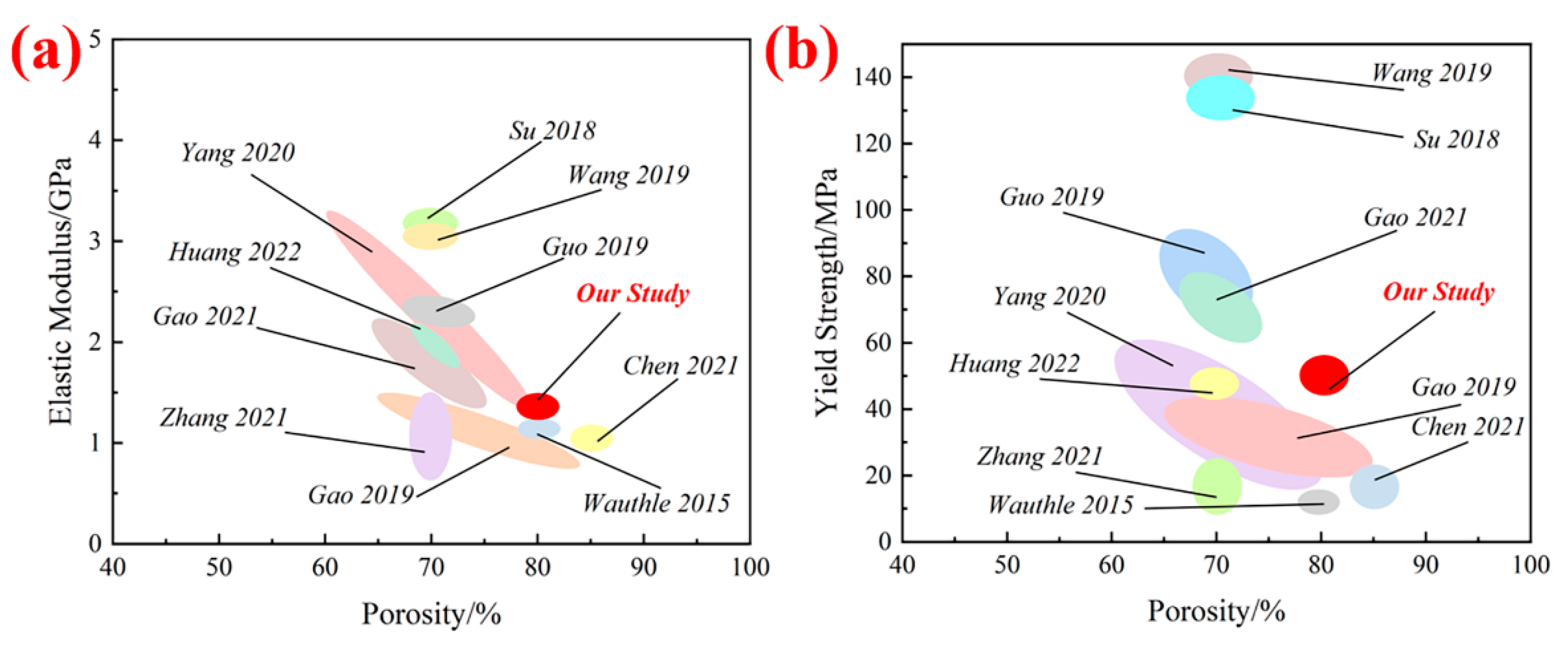
This article systematically studied the influence of different process parameters on the forming quality of porous Ta samples using an orthogonal experimental plan. Figure 10 shows a comparison summary of the mechanical properties of current studies. Generally speaking, the equivalent elastic modulus and yield strength of the porous structures were obtained from compressive stress–strain curves, and there was a certain positive correlation between them: the greater the equivalent elastic modulus was, the greater the yield strength would be. The results show that the elastic modulus (1.352 ± 0.007 GPa) and yield strength (53.217 ± 0.114 MPa) of the porous Ta samples with porosities of 80% under the optimal process parameters were significantly superior to other studies, due to the better forming quality, which significantly improved the mechanical properties. The elastic modulus of the porous Ta fabricated by the optimal L-PBF process was 1.352 GPa, much smaller than the original value. The reason might be inevitable pores inside the porous Ta struts due to the limitations of the L-PBF processing, thereby affecting the mechanical properties of the porous Ta samples. Additionally, there was a stress concentration effect at the strut joints, and this effect was further exacerbated during the forming process, resulting in decreases in the mechanical properties. This was mainly because there were sharp corners at the joint of the struts, which easily produce stress concentration and led to cracks during the loading process, and then the structure was damaged. Therefore, the potential strategies could be inferred. For example, the corners of the strut junctions could be optimized to produce a smooth transition.
In comparing previous studies on the LPBF processing parameters of porous Ta scaffolds [10,19,30,31,32,33,34,35,36,37,38], it was found that a relatively smaller powder layer thickness and scanning spacing might lead to over-melting at the lap joints between adjacent layers at a certain depth of molten pools [30,38], resulting in reduced mechanical properties of the structures. In particular, a smaller powder layer thickness of 0.01 mm was revealed to produce larger size errors of the manufactured samples [34]. Meanwhile, a larger layer thickness could generate more spherical Ta particles sticking to the struts [36]. The smaller laser power and powder layer thickness may cause incompletely melted powders with larger particle sizes [15,39], thus affecting the mechanical properties.
Some previous studies proposed the optimal processing parameters for the forming quality of dense Ta blocks (laser power: 150 W; scanning speed: 300 mm/s; powder layer thickness: 0.02–0.04 mm; scanning spacing: 0.04–0.06 mm) [20,21,22,40]. The printing parameters of porous Ta studied by predecessors were almost the same as those of compact Ta. In particular, the laser power was generally lower than 180 W. This resulted in poor forming quality of the porous Ta surface, leading to low mechanical properties. Noticeably, there was a significant difference in the thickness of the powder layer and the scanning spacing in the optimal process parameters for the fabrication of dense Ta and porous Ta. This was due to the presence of porosity in the porous structures, which made it easier for the high heat generated inside the molten pool to dissipate during the preparation process. Therefore, the values of the thickness of the powder layer and the scanning spacing can be larger in the manufacture of porous Ta samples. On the other hand, some researcher prepared porous Ta samples with 80% porosity by using SEBM [19] and EBPBF technologies [37], respectively. The forming quality and mechanical properties of the structures were lower than those in this study, indicating that the preparation of porous Ta implants by L-PBF had obvious advantages compared to other preparation processes.
This study aimed to manufacture porous Ta with superior mechanical properties that match those of human cortical bone under higher porosity conditions, making it more advantageous as an orthopedic implant. At the same time, due to the limitation of the technology and time, the microscopic characterization of porous tantalum compression process was lacking. It is also a potential area of future research to solve the stress concentration effects of porous Ta structures, which has important significance for the research of metal bone implants.
4. Conclusions
In order to systematically study the process parameters of L-PBF preparation of porous Ta, we used orthogonal experimental methods to investigate the effects of different process parameters on the forming quality. Moreover, we also studied the mechanical properties of the formed samples under different process parameters. The main findings included:
(1) The optimal process parameters for the preparation of porous Ta were obtained (laser power: 180 W; scanning speed: 270 mm/s; thickness: 0.05 mm; scanning spacing: 0.07 mm).
(2) The equivalent elastic modulus and yield strength of porous Ta prepared by the optimal process parameters were 1.352 ± 0.007 GPa and 53.217 ± 0.114 MPa, respectively.
(3) The mechanical properties of the porous Ta with 80% porosity developed by us were superior to those of previous studies. This provides theoretical support for the subsequent manufacture of porous Ta orthopedic implants.
Author Contributions
Conceptualization, L.G.; methodology, Y.W., X.Q. and Z.T.; software, N.L. and C.S.; validation, L.G., X.Q. and Y.W.; resources, D.L.; data curation, X.Q.; writing—original draft preparation, L.G. and Y.W.; writing—review and editing, L.G. and C.S.; supervision, D.L.; project administration, L.G.; funding acquisition, L.G. All authors have read and agreed to the published version of the manuscript.
Funding
This work is supported in part by the Key R&D Program of Ningxia Province (grant number 2020BCH01001), the National Natural Science Foundation of China (grant number 52175276), University Joint Project of Shaanxi Province (grant number 2020GXLH-Y-025), Program for Innovation Team of Shaanxi Province (2023-CX-TD-17).
Data Availability Statement
The data presented in this study are available upon request from the corresponding author.
Acknowledgments
Thanks to Teacher Xiaoping Li for his help and guidance in the early stage of this study.
Conflicts of Interest
The authors declare no conflict of interest.
References
- Wauthle, R.; van der Stok, J.; Yavari, S.A.; Humbeeck, J.V.; Kruth, J.P.; Zadpoor, A.A.; Weinans, H.; Mulier, M.; Schrooten, J. Additively manufactured porous tantalum implants. Acta Biomater. 2015, 14, 217–225. [Google Scholar] [CrossRef] [PubMed]
- Gao, H.; Jin, X.; Yang, J.; Zhang, D.; Zhang, S.; Zhang, F.; Chen, H. Porous structure and compressive failure mechanism of additively manufactured cubic-lattice tantalum scaffolds. Mater. Today Adv. 2021, 12, 100183. [Google Scholar] [CrossRef]
- Dong, C.; Bi, X.L.; Yu, J.G.; Liu, R.; Zhang, Q.X. Microstructural evolution and sintering kinetics during spark plasma sintering of pure tantalum powder. J. Alloys Compd. 2019, 781, 84–92. [Google Scholar] [CrossRef]
- Balla, V.K.; Bodhak, S.; Bose, S.; Bandyopadhyay, A. Porous tantalum structures for bone implants: Fabrication, mechanical and in vitro biological properties. Acta Biomater. 2010, 6, 3349–3359. [Google Scholar] [CrossRef]
- Fernandez-Fairen, M.; Querales, V.; Jakowlew, A.; Murcia, A.; Ballester, J. Tantalum is a good bone graft substitute in tibial tubercle advancement. Clin. Orthop. Relat. Res. 2010, 468, 1284–1295. [Google Scholar] [CrossRef]
- Liu, Y.; Bao, C.; Wismeijer, D.; Wu, G. The physicochemical/biological properties of porous tantalum and the potential surface modification techniques to improve its clinical application in dental implantology. Mater. Sci. Eng. C 2015, 49, 323–329. [Google Scholar] [CrossRef]
- Wang, Q.; Zhang, H.; Li, Q.J.; Ye, L.; Gan, H.Q.; Liu, Y.J.; Wang, H.; Wang, Z.Q. Biocompatibility and osteogenic properties of porous tantalum. Exp. Ther. Med. 2015, 9, 780–786. [Google Scholar] [CrossRef]
- Gracia, M.A.A. Osseoincorporation of porous tantalum trabecular-structured metal: A histologic and histomorphometric study in humans. Int. J. Periodontics Restor. Dent. 2018, 38, 879–885. [Google Scholar]
- Dou, X.J.; Wei, X.W.; Liu, G.; Wang, S.; Lv, Y.X.; Li, J.L.; Ma, Z.J.; Zheng, G.S.; Wang, Y.K.; Hu, M.H.; et al. Effect of porous tantalum on promoting the osteogenic differentiation of bone marrow mesenchymal stem cells in vitro through the MAPK/ERK signal pathway. J. Orthop. Transl. 2019, 19, 81–93. [Google Scholar] [CrossRef]
- Guo, Y.; Xie, K.; Jiang, W.B.; Wang, L.; Li, G.Y.; Zhao, S.; Wu, W.; Hao, Y.Q. In vitro and in vivo study of 3D-printed porous tantalum scaffolds for repairing bone defects. ACS Biomater. Sci. Eng. 2019, 5, 1123–1133. [Google Scholar]
- Piglionico, S.; Bousquet, J.; Fatima, N.; Renaud, M.; Collart-Dutilleul, P.-Y.; Bousquet, P. Porous tantalum VS. Titanium implants: Enhanced mineralized matrix formation after stem cells proliferation and differentiation. J. Clin. Med. 2020, 9, 3657. [Google Scholar] [CrossRef]
- Jia, C.Q.; Zhang, Z.; Cao, S.Q.; Wang, T.J.; Yu, H.C.; Wang, W.X.; Guo, B.M.; Qiu, X.Y.; You, Y.G.; Hu, F.Q.; et al. A biomimetic gradient porous cage with a micro-structure for enhancing mechanical properties and accelerating osseointegration in spinal fusion. Bioact. Mater. 2023, 23, 234–246. [Google Scholar] [CrossRef]
- Zhao, D.W.; Ma, Z.J.; Wang, T.N.; Liu, B.Y. Biocompatible porous tantalum metal plates in the treatment of tibial fracture. Orthop. Surg. 2019, 11, 325–329. [Google Scholar] [CrossRef]
- Sagherian, B.H.; Claridge, R.J. The use of tantalum metal in foot and ankle surgery. Orthop. Clin. N. Am. 2019, 50, 119–129. [Google Scholar] [CrossRef]
- Zhou, L.; Yuan, T.; Li, R.; Tang, J.; Wang, G.; Guo, K. Selective laser melting of pure tantalum: Densification, microstructure and mechanical behaviors. Mater. Sci. Eng. A 2017, 707, 443–451. [Google Scholar] [CrossRef]
- Bartolomeu, F.; Faria, S.; Carvalho, O.; Pinto, E.; Alves, N.; Silva, F.S.; Miranda, G. Predictive Models for physical and mechanical properties of ti6al4v produced by selective laser melting. Mater. Sci. Eng. A 2016, 663, 181–192. [Google Scholar] [CrossRef]
- Miranda, G.; Faria, S.; Bartolomeu, F.; Pinto, E.; Madeira, S.; Mateus, A.; Carreira, P.; Alves, N.; Silva, F.S.; Carvalho, O. Predictive models for physical and mechanical properties of 316l stainless steel produced by selective laser melting. Mater. Sci. Eng. A 2016, 657, 43–56. [Google Scholar] [CrossRef]
- Huang, S.; Sing, S.L.; de Looze, G.; Wilson, R.; Yeong, W.Y. Laser powder bed fusion of titanium-tantalum alloys: Compositions and designs for biomedical applications. J. Mech. Behav. Biomed. Mater. 2020, 108, 103775. [Google Scholar] [CrossRef]
- Tang, H.P.; Yang, K.; Jia, L.; He, W.W.; Yang, L.; Zhang, X.Z. Tantalum bone implants printed by selective electron beam manufacturing (SEBM) and their clinical applications. JOM 2020, 72, 1016–1021. [Google Scholar] [CrossRef]
- Ghouse, S.; Babu, S.; Nai, K.; Hooper, P.A.; Jeffers, J.R.T. The influence of laser parameters, scanning strategies and material on the fatigue strength of a stochastic porous structure. Addit. Manuf. 2018, 22, 290–301. [Google Scholar] [CrossRef]
- Song, C.; Deng, Z.; Zou, Z.; Liu, L.; Xu, K.; Yang, Y. Pure tantalum manufactured by laser powder bed fusion: Influence of scanning speed on the evolution of microstructure and mechanical properties. Int. J. Refract. Met. Hard Mater. 2022, 107, 105882. [Google Scholar] [CrossRef]
- Livescu, V.; Knapp, C.M.; Gray, G.T.; Martinez, R.M.; Morrow, B.M.; Ndefru, B.G. Additively manufactured tantalum microstructures. Materialia 2018, 1, 15–24. [Google Scholar] [CrossRef]
- Băb, A.M.; Timu, D.; Sori, O.; Bo, B.A.; Barabas, R.; Ionel, A.; Petrescu, N.B.; Feurdean, C.N.; Bordea, I.R.; Saraci, G.; et al. Tissue integration and biological cellular response of SLM-manufactured titanium scaffolds. Metals 2020, 10, 1192. [Google Scholar]
- Huang, S.; Zhang, X.; Li, D.; Li, Q. Microstructure and mechanical properties of b-bearing austenitic stainless steel fabricated by laser metal deposition in-situ alloying. Acta Metall. Sin. (Engl. Lett.) 2022, 35, 453–465. [Google Scholar] [CrossRef]
- Chen, X.; Sun, G.; Zhu, J.; Kang, W.; Shang, D.; Deng, Z. Influence of structural parameters on mechanical properties of triply periodic minimal surface structure. Metals 2023, 13, 285. [Google Scholar] [CrossRef]
- ISO 13314; Mechanical testing of metals—Ductility testing—Compression test for porous and cellular metals. ISO Central Secretariat: Geneva, Switzerland, 2011.
- Antony, K.; Arivazhagan, N.; Senthilkumaran, K. Numerical and experimental investigations on laser melting of stainless steel 316L metal powders. J. Manuf. Process. 2014, 16, 345–355. [Google Scholar] [CrossRef]
- Khorasani, A.M.; Gibson, I.; Ghasemi, A.; Ghaderi, A. A Comprehensive Study on Variability of Relative Density in Selective Laser Melting of Ti-6Al-4V. Virtual Phys. Prototyp. 2019, 14, 349–359. [Google Scholar] [CrossRef]
- Rana, R.S.; Rajesh, P.; Mishra, P.M.; Sahu, P.; Dwivedi, S. Shailendra. Optimization of mechanical properties of AA 5083 nano SiC composites using design of experiment technique. Mater. Today Proc. 2017, 4, 3882–3890. [Google Scholar] [CrossRef]
- Zhao, G.B.; Li, S.S.; Chen, X.; Qu, X.L.; Chen, R.M.; Wu, Y.L.; Liu, Y.X.; Zou, X.L.; Lu, X.G. Porous tantalum scaffold fabricated by gel casting based on 3D printing and electrolysis. Mater. Lett. 2019, 239, 5–8. [Google Scholar] [CrossRef]
- Su, K.X.; Ji, P.; Wang, H.; Li, L.L.; Su, L.Z.; Wang, C. In vivo study of 3D printed porous tantalum implant on osseointegration. West China J. Stomatol. 2018, 36, 291–295. [Google Scholar]
- Jiao, J.Y.; Hong, Q.M.; Zhang, D.C.; Wang, M.Q.; Tang, H.Z.; Yang, J.Z.; Qu, X.H.; Yue, B. Influence of porosity on osteogenesis, bone growth and osteointegration in trabecular tantalum scaffolds fabricated by additive manufacturing. Front. Bioeng. Biotechnol. 2023, 11, 1117954. [Google Scholar] [CrossRef] [PubMed]
- Gao, R.N.; Xiong, Y.Z.; Zhang, H.; Dong, L.L.; Li, J.T.; Li, X. Mechanical properties and biocompatibilities of radially graded porous titanium/tantalum fabricated by selective laser melting. Rare Met. Mater. Eng. 2021, 50, 249–254. [Google Scholar]
- Chen, W.L.; Yang, J.Z.; Kong, H.; Helou, M.; Zhang, D.C.; Zhao, J.H.; Jia, W.T.; Liu, Q.; He, P.D.; Li, X.P. Fatigue behaviour and biocompatibility of additively manufactured bioactive tantalum graded lattice structures for load-bearing orthopaedic applications. Mater. Sci. Eng. C 2021, 130, 112461. [Google Scholar] [CrossRef] [PubMed]
- Fan, H.Q.; Deng, S.; Tang, W.T.; Muheremu, A.; Wu, X.Z.; He, P.; Tan, C.H.; Wang, G.H.; Tang, J.Z.; Guo, K.X. Highly porous 3D printed tantalum scaffolds have better biomechanical and microstructural properties than titanium scaffolds. BioMed Res. Int. 2021, 2021, 1–8. [Google Scholar] [CrossRef]
- Zhang, T.M.; Chen, C.; Dong, J.; Wu, Y.Y.; Qian, H.; Lei, T.; Lei, P.F.; Zhou, K.C. Microstructure and biocompatibility of porous-Ta/Ti-6Al-4 V component produced by laser powder bed fusion for orthopedic implants. Mater. Charact. 2021, 182, 111554. [Google Scholar] [CrossRef]
- Guo, Y.; Chen, C.; Wang, Q.B.; Liu, M.; Cao, Y.K.; Pan, Y.M.; Tan, L.M. Effect of porosity on mechanical properties of porous tantalum scaffolds produced by electron beam powder bed fusion. Trans. Nonferrous Met. Soc. China 2022, 32, 2922–2934. [Google Scholar] [CrossRef]
- Li, H.J.; Yang, G.L.; Lv, S.J.; Zhou, Q.; Fan, L.S.; Liu, R.; Yao, J.H.; Tong, P.J. Effects of unit cell topology on the mechanical propeties of porous tantalum structures via laser powder bed fusion. Adv. Eng. Mater. 2023, 25, 2201431. [Google Scholar] [CrossRef]
- Thijs, L.; Sistiaga, M.L.M.; Wauthle, R.; Xie, Q.G.; Kruth, J.P.; Humbeeck, J.V. Strong morphological and crystallographic texture and resulting yield strength anisotropy in selective laser melted tantalum. Acta Mater. 2013, 61, 4657–4668. [Google Scholar] [CrossRef]
- Wu, X.; Luo, K.; Wang, Q.; Liu, H.; Wang, F.; Wang, P.; Lan, J. Study on the influence of forming Parameters of laser selective melting tantalum metal on its density and defects. Laser J. 2019, 41, 8–14. [Google Scholar]
Figure 1.
Microstructure design of a porous Ta scaffold with diamond unit cells. (a) An independent diamond unit structure; (b) a porous Ta scaffold modeling used for the L-PBF manufacturing (length × width × height = 12 × 12 × 12 mm3); (c) the x-y-z directions of porous Ta scaffold.
Figure 1.
Microstructure design of a porous Ta scaffold with diamond unit cells. (a) An independent diamond unit structure; (b) a porous Ta scaffold modeling used for the L-PBF manufacturing (length × width × height = 12 × 12 × 12 mm3); (c) the x-y-z directions of porous Ta scaffold.
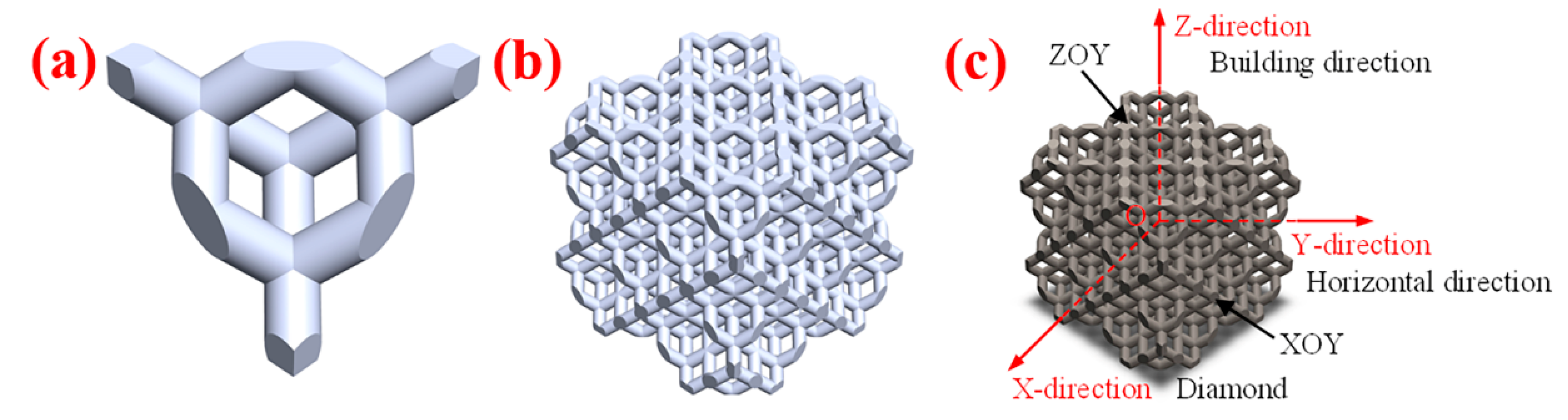
Figure 2.
Morphology and particle size of pure Ta powder. (a) SEM morphology of Ta powder; (b) particle size distribution curve of Ta powder.
Figure 2.
Morphology and particle size of pure Ta powder. (a) SEM morphology of Ta powder; (b) particle size distribution curve of Ta powder.

Figure 3.
Macroscopic photographs of the porous Ta scaffolds samples. (a) Macroscopic photographs and (b) macroscopic geometry size.
Figure 3.
Macroscopic photographs of the porous Ta scaffolds samples. (a) Macroscopic photographs and (b) macroscopic geometry size.

Figure 4.
SEM micrographs showing the microscopic porous structure of the Ta scaffolds along (a) the building direction and (b) the horizontal direction.
Figure 4.
SEM micrographs showing the microscopic porous structure of the Ta scaffolds along (a) the building direction and (b) the horizontal direction.
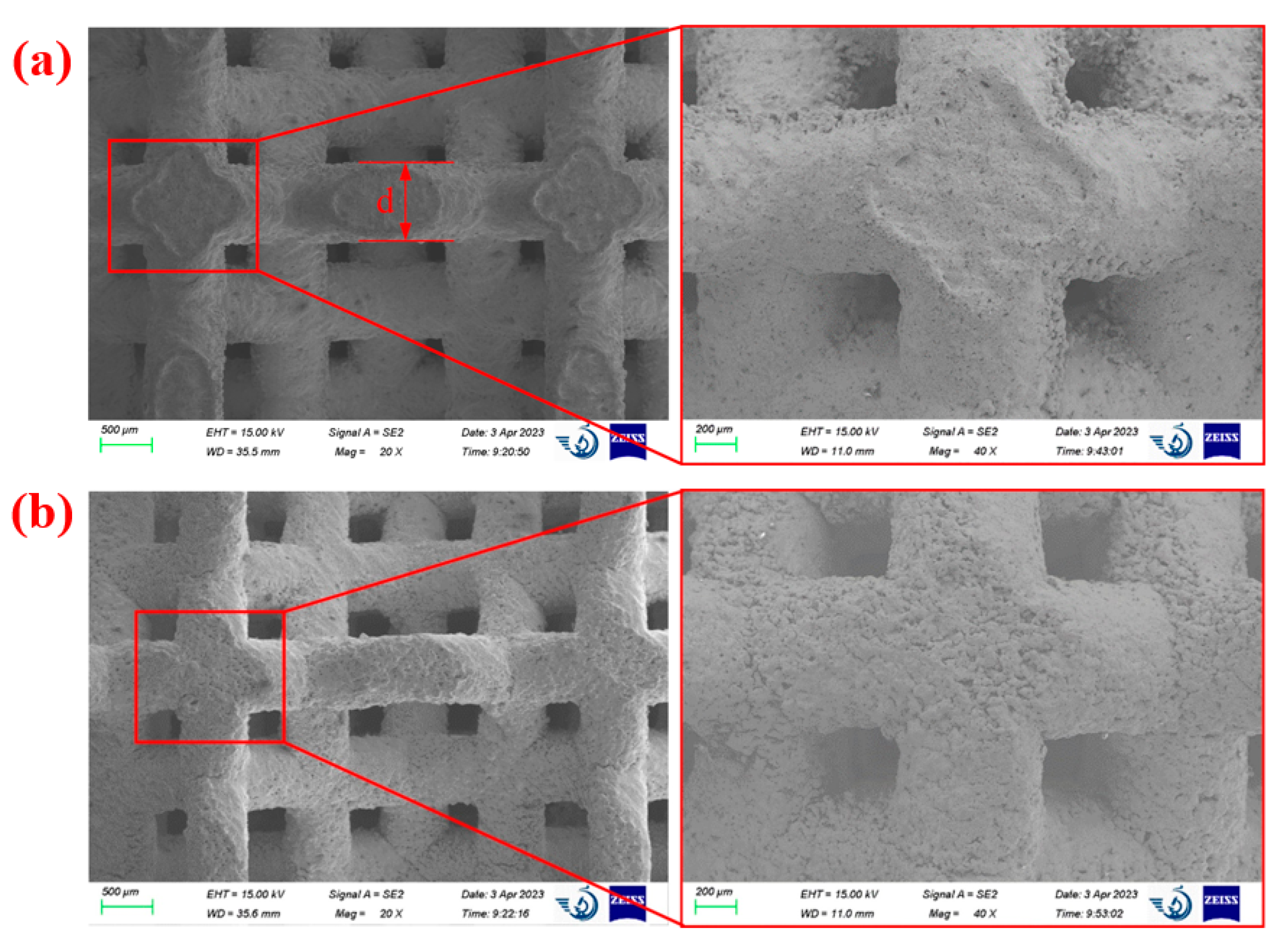
Figure 5.
Photographical morphologies of the porous Ta structure before and after a compression test. (a) Original shape. (b) Destructive morphology after the compression test.
Figure 5.
Photographical morphologies of the porous Ta structure before and after a compression test. (a) Original shape. (b) Destructive morphology after the compression test.
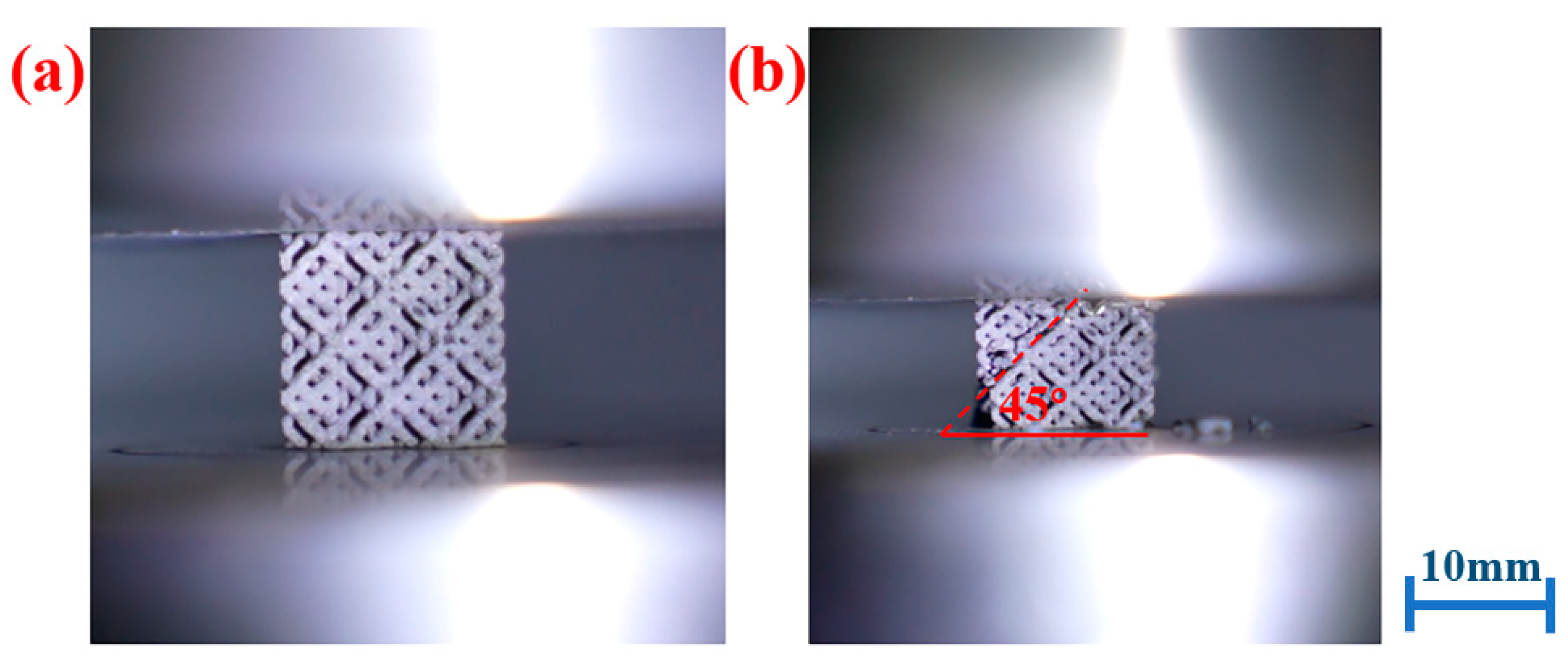
Figure 6.
Compressive stress–strain curves of the typical porous Ta samples in (a) the building direction and (b) the horizontal direction.
Figure 6.
Compressive stress–strain curves of the typical porous Ta samples in (a) the building direction and (b) the horizontal direction.

Figure 7.
Compressive properties of the L-PBF porous Ta structures in the horizontal direction (Y) and the building direction (Z), respectively, including (a) elastic modulus, (b) yield strengths.
Figure 7.
Compressive properties of the L-PBF porous Ta structures in the horizontal direction (Y) and the building direction (Z), respectively, including (a) elastic modulus, (b) yield strengths.
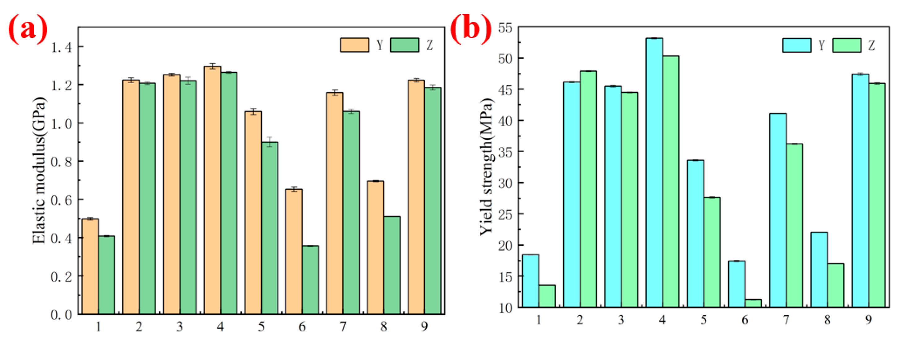
Figure 8.
Relationships among three levels of the process parameters and the forming quality parameters including geometry properties of (a) difference value of the strut diameter in the building direction, (b) difference value of the porosity, and (c) mechanical characteristics of the elastic modulus.
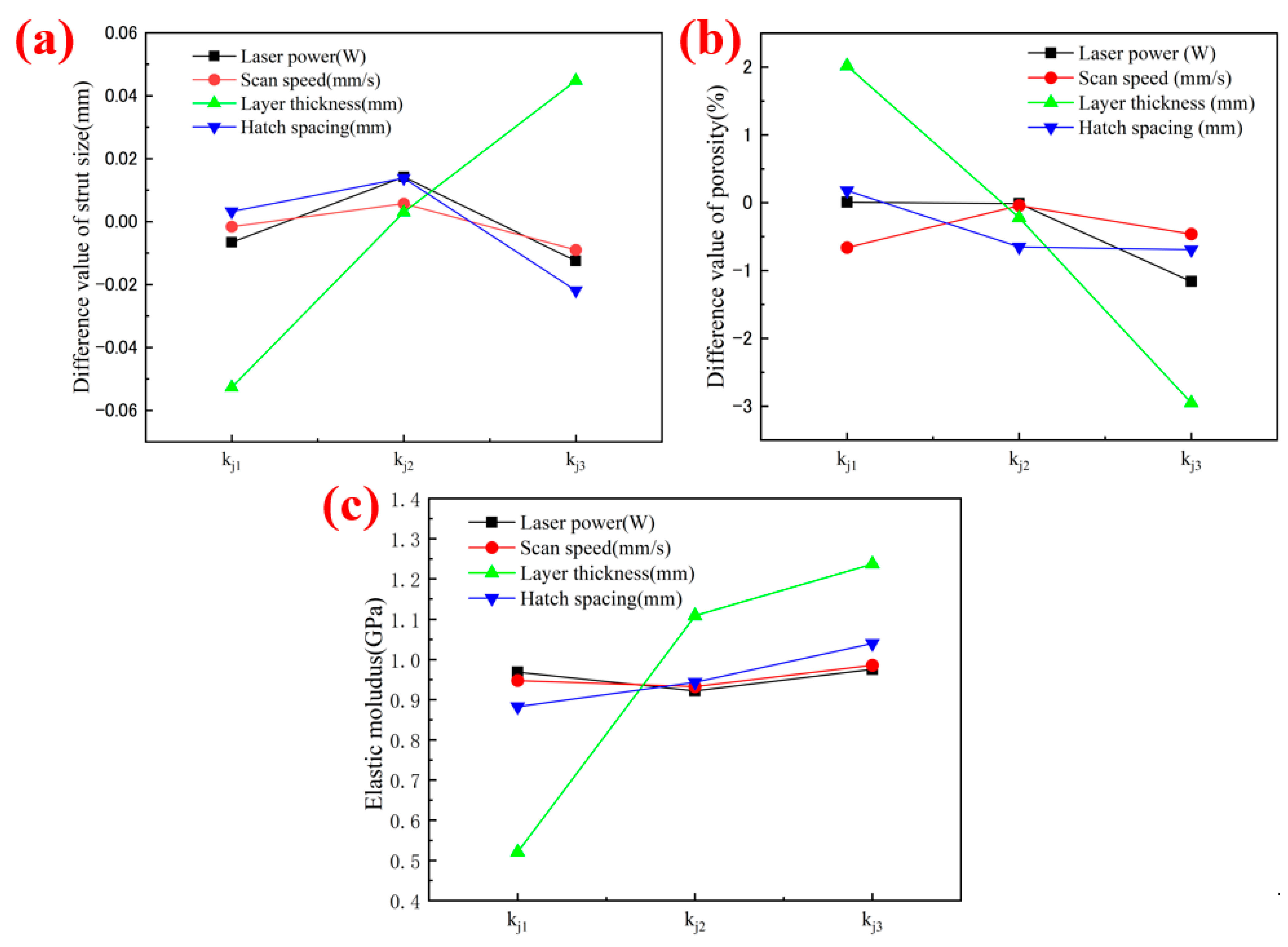
Figure 9.
Microstructure morphology of the porous Ta prepared by the optimal L-PBF process along (a) the horizontal direction and (b) the building direction.
Figure 9.
Microstructure morphology of the porous Ta prepared by the optimal L-PBF process along (a) the horizontal direction and (b) the building direction.

Figure 10.
Mechanical property comparisons of the porous Ta scaffolds between our study and previous studies in (a) elastic modulus and (b) yield strength (data from Refs. [10,19,30,31,32,33,34,35,36,37,38]).

Table 1.
Chemical composition of spherical Ta powder used in this study (wt%).
| Element | O | C | N | H | Fe | Ni | Ti | Ta |
|---|---|---|---|---|---|---|---|---|
| Standard values | ≤0.03 | ≤0.01 | ≤0.01 | ≤0.015 | ≤0.03 | ≤0.01 | ≤0.01 | Balance |
| Measured values | 0.02 | 0.0088 | <0.001 | <0.0015 | <0.01 | 0.0016 | 0.001 | Balance |
Table 2.
Process parameters of the samples in orthogonal experiment.
| Number | Laser Power (W) | Scanning Speed (mm/s) | Thickness (mm) | Scan Spacing (mm) |
|---|---|---|---|---|
| 1 | 120 | 270 | 0.03 | 0.05 |
| 2 | 120 | 300 | 0.05 | 0.06 |
| 3 | 120 | 330 | 0.04 | 0.07 |
| 4 | 150 | 270 | 0.05 | 0.07 |
| 5 | 150 | 300 | 0.04 | 0.05 |
| 6 | 150 | 330 | 0.03 | 0.06 |
| 7 | 180 | 270 | 0.04 | 0.06 |
| 8 | 180 | 300 | 0.03 | 0.07 |
| 9 | 180 | 330 | 0.05 | 0.05 |
Table 3.
Geometry characteristics of the L-PBF-fabricated porous Ta scaffolds.
| Number | 1 | 2 | 3 | 4 | 5 | 6 | 7 | 8 | 9 |
|---|---|---|---|---|---|---|---|---|---|
| Porosity (%) | 82.7 ± 0.061 | 77.5 ± 0.012 | 79.8 ± 0.025 | 76.9 ± 0.020 | 81.1 ± 0.040 | 82.1 ± 0.035 | 78.5 ± 0.012 | 81.3 ± 0.181 | 76.8 ± 0.012 |
| Strut diameter in building direction (μm) | 699.1 ± 4.384 | 783.7 ± 0.071 | 740.5 ± 1.626 | 797.1 ± 2.051 | 769.8 ± 2.758 | 724.0 ± 1.980 | 798.7 ± 10.112 | 752.8 ± 2.051 | 783.1 ± 13.223 |
| Strut diameter in horizontal direction (μm) | 782.4 ± 6.131 | 828.2 ± 2.864 | 846.9 ± 7.085 | 892.7 ± 7.000 | 877.4 ± 7.693 | 841.9 ± 9.659 | 856.5 ± 3.514 | 861.1 ± 7.311 | 861.6 ± 5.537 |
Table 4.
Range analysis results of the strut diameters of porous Ta samples with different process parameters.
Table 4.
Range analysis results of the strut diameters of porous Ta samples with different process parameters.
| Process Parameters | Laser Power (A) | Scanning Speed (B) | Thickness © | Scanning Spacing (D) |
|---|---|---|---|---|
| kj1 | 0.7606 | 0.7847 | 0.7511 | 0.7731 |
| kj2 | 0.7904 | 0.7905 | 0.7923 | 0.7871 |
| kj3 | 0.7986 | 0.7744 | 0.8062 | 0.7893 |
| Rj | 0.0380 | 0.0161 | 0.0551 | 0.0162 |
Table 5.
Range analysis results of the porosities of porous Ta samples with different process parameters.
Table 5.
Range analysis results of the porosities of porous Ta samples with different process parameters.
| Process Parameters | Laser Power | Scanning Speed | Thickness | Scanning Spacing |
|---|---|---|---|---|
| kj1 | 0.8001 | 0.7934 | 0.8202 | 0.8018 |
| kj2 | 0.7999 | 0.7996 | 0.7978 | 0.7935 |
| kj3 | 0.7884 | 0.7954 | 0.7705 | 0.7931 |
| Rj | 0.0118 | 0.0062 | 0.0497 | 0.0086 |
Table 6.
Range analysis results of the elastic moduli of porous Ta samples with different process parameters.
Table 6.
Range analysis results of the elastic moduli of porous Ta samples with different process parameters.
| Process Parameters | Laser Power | Scanning Speed | Thickness | Scanning Spacing |
|---|---|---|---|---|
| kj1 | 0.9687 | 0.9477 | 0.5210 | 0.8828 |
| kj2 | 0.9222 | 0.9330 | 1.1087 | 0.9435 |
| kj3 | 0.9758 | 0.9860 | 1.2370 | 1.0403 |
| Rj | 0.0537 | 0.0530 | 0.7160 | 0.1575 |
Table 7.
Variance analysis results of the strut diameter of the porous Ta samples.
| Source | Sum of Deviation Squares | Degree of Freedom | Mean Square Deviation | F Value | Significance Level | Contribution |
|---|---|---|---|---|---|---|
| Laser power | 0.007 | 2 | 0.004 | 95.023 | (*) | 14.14% |
| Scanning speed | 0.004 | 2 | 0.002 | 49.943 | 7.36% | |
| Thickness | 0.033 | 2 | 0.017 | 432.657 | * | 64.91% |
| Scanning spacing | 0.006 | 2 | 0.003 | 78.424 | (*) | 11.64% |
| Error | 0.001 | 18 | 0.000 | 1.95% |
Note: ‘(*)’ indicates that this factor had an impact on the experimental results, and ‘*’ indicates that this factor had a significant impact.
Table 8.
Variance analysis results of the porosity of porous Ta samples.
| Source | Sum of Deviation Squares | Degree of Freedom | Mean Square Deviation | F Value | Significance Level | Contribution |
|---|---|---|---|---|---|---|
| Laser power | 0.001 | 2 | 0.000 | 1366.238 | 6.51% | |
| Scanning speed | 0.000 | 2 | 0.000 | 301.976 | 1.43% | |
| Thickness | 0.011 | 2 | 0.006 | 18,592.609 | * | 88.60% |
| Scanning spacing | 0.000 | 2 | 0.000 | 709.876 | 3.38% | |
| Error | 0.00001 | 27 | 0.00000 | 0.08% |
Note: ‘*’ indicates that this factor had a significant impact on the experimental results.
Table 9.
The variance analysis results of the elastic modulus of porous Ta samples.
| Source | Sum of Deviation Squares | Degree of Freedom | Mean Square Deviation | F Value | Significance Level | Contribution |
|---|---|---|---|---|---|---|
| Thickness | 1.749 | 2 | 0.875 | 108.624 | * | 89.82% |
| Other sources | 0.076 | 2 | 0.038 | 4.703 | 3.09% | |
| Error | 0.105 | 13 | 0.008 | 7.09% |
Note: ‘*’ indicates that this factor had a significant impact on the experimental results.
Table 10.
Forming quality comparison of the porous Ta samples after process optimization.
| L-PBF Process | Porosity/% | Strut Diameter/mm | Elastic Modulus/GPa | ||
|---|---|---|---|---|---|
| Horizontal Direction | Building Direction | Horizontal Direction | Building Direction | ||
| Group 4 (150 W, 270 mm/s, 0.05 mm, 0.07 mm) | 75.11 ± 0.11 | 0.892 ± 0.014 | 0.797 ± 0.012 | 1.296 ± 0.015 | 1.265 ± 0.006 |
| Optimized process (180 W, 270 mm/s, 0.05 mm, 0.07 mm) | 74.00 ± 0.13 | 0.857 ± 0.009 | 0.803 ± 0.010 | 1.352 ± 0.007 | 1.298 ± 0.006 |
Disclaimer/Publisher’s Note: The statements, opinions and data contained in all publications are solely those of the individual author(s) and contributor(s) and not of MDPI and/or the editor(s). MDPI and/or the editor(s) disclaim responsibility for any injury to people or property resulting from any ideas, methods, instructions or products referred to in the content. |
© 2023 by the authors. Licensee MDPI, Basel, Switzerland. This article is an open access article distributed under the terms and conditions of the Creative Commons Attribution (CC BY) license (https://creativecommons.org/licenses/by/4.0/).
Share and Cite
MDPI and ACS Style
Gao, L.; Wang, Y.; Qin, X.; Lv, N.; Tong, Z.; Sun, C.; Li, D. Optimization of Laser Powder Bed Fusion Process for Forming Porous Ta Scaffold. Metals 2023, 13, 1764. https://doi.org/10.3390/met13101764
AMA Style
Gao L, Wang Y, Qin X, Lv N, Tong Z, Sun C, Li D. Optimization of Laser Powder Bed Fusion Process for Forming Porous Ta Scaffold. Metals. 2023; 13(10):1764. https://doi.org/10.3390/met13101764
Chicago/Turabian StyleGao, Lin, Yikai Wang, Xiao Qin, Naixin Lv, Zhiqiang Tong, Changning Sun, and Dichen Li. 2023. "Optimization of Laser Powder Bed Fusion Process for Forming Porous Ta Scaffold" Metals 13, no. 10: 1764. https://doi.org/10.3390/met13101764
Note that from the first issue of 2016, this journal uses article numbers instead of page numbers. See further details here.