Electron Beam Welding and Post Heat Treatment of a New Near-Beta High-Strength Ti-4Al-5Mo-5V-5Cr-1Nb Alloy


1
School of Materials, Northwestern Polytechnical University, Xi’an 710072, China
2
The First Aircraft Institute of AVIC, Xi’an 710089, China
3
Chongqing Innovation Center, Northwestern Polytechnical University, Chongqing 401120, China
*
Author to whom correspondence should be addressed.
Metals 2022, 12(8), 1396; https://doi.org/10.3390/met12081396
Submission received: 11 July 2022
/
Revised: 11 August 2022
/
Accepted: 15 August 2022
/
Published: 22 August 2022
Abstract
:Ti-4Al-5Mo-5V-5Cr-1Nb (wt.%) is a new type of high-strength (~1300 MPa) titanium (Ti) alloy developed for aerospace applications. Until now, the research on its welding and subsequent heat treatment is barren. Herein, we employed electron beam welding (EBW) to a solutionized Ti-4Al-5Mo-5V-5Cr-1Nb with a phase constituent of α + β and investigated its microstructure and mechanical properties in both as-welded (AW) and post-weld aging treated (PWAT) conditions. Results showed that due to the thermal input of the welding process, the α phase in the original microstructure of base material (BM) transformed into the β phase in the fusion zone (FZ). Similar microstructural evolution was observed for the heat-affected zone (HAZ) near the FZ (Near-HAZ), whereas the HAZ far away from FZ (Far-HAZ) contained a small amount of round α phase (ghost α) due to its slower cooling rate. Such a microstructural change resulted in poor tensile strength (~780 Mpa) for the as-welded joint. After PWAT, a large number of acicular α precipitated in the FZ and HAZ and its size (S) in different zones followed the order of SFar-HAZ < SFZ ≈ SNear-HAZ < SBM. The presence of αs precipitates remedied the tensile strength of the weld joint almost to the same as that of the BM. The present findings established the foundation of the application of this high-strength Ti alloy.
1. Introduction
Beneficial from the high specific strength, good fracture toughness, excellent corrosion resistance, etc., metastable β titanium alloys are widely used for landing gears, beams, fasteners, and other important loading parts of aircraft [1,2,3]. In order to reduce the consumption of raw materials and the weight of structural parts, the connection technology of welding is frequently used in the titanium alloy manufacture process [4,5,6]. The main methods of welding include linear friction welding (LFW), gas tungsten arc welding (GTAW), laser beam welding (LBW), and electron beam welding (EBW) [7,8,9,10]. Compared with other welding methods, electron beam welding has a high energy density and a low heat input. Moreover, it is carried out in a vacuum, which can effectively prevent titanium alloys from reacting with the atmosphere [11]. Owing to these characteristics, EBW is widely adopted to join thick titanium alloy [12,13,14].
Owing to the different heat inputs across various zones, the structure of the weld joint from EBW is nonuniform and could be fairly complicated. In general, the weld joint can be divided into three zones: base material (BM), heat affected zone (HAZ), and fusion zone (FZ). Up to date, a lot of efforts have been made to investigate the microstructure and mechanical properties of EBW joints for titanium alloy. Liu et al. [10,12] investigated the microstructure and mechanical properties of electron beam welded TC17 titanium alloy in both as-welded (AW) and post-weld aging treatment (PWAT) conditions. It was pointed out that due to a high cooling rate during the EBW process, the acicular martensitic α’ phase was generated in the FZ. Consequently, the hardness of FZ was greater than that of BM. Compared with as-received (AR) materials, the TC17 titanium alloy welded joint is poor in tensile strength and ductility. After PWAT, the α’ martensite phase recrystallized and formed α lamella with a width in nanosize, enhancing the strength and ductility. In addition, there are many investigations on the welding of Ti–6Al–4V alloy [15,16,17,18]. They indicated that the weldment exhibited a comparable strength and a poor ductility to the base metal, which can be attributed to the formation of α’ martensite from the prior β phase in FZ and HAZ. Similar results apply to the EBW of near α titanium alloys [19].
There had been some works on the microstructure and mechanical properties of metastable β titanium alloys by welding [8,20,21,22]. The results indicated that the microhardness of the FZ and HAZ was lower than that of the BM, which was greatly different from that of the above-mentioned near α titanium alloys or (α + β) titanium alloys. The reason for the decrease of microhardness in FZ was that the α phase transformed into the β phase at high temperatures. However, there are rare investigations on the microstructure and mechanical properties of electron beam welded metastable β titanium alloys. The existing studies are not clear on the microstructure of each zone of the weld joint, and the effect of post-weld heat treatment has not been studied. Ti-4Al-5Mo-5V-5Cr-1Nb alloy (Ti-45551, wt.%) is a newly developed metastable β titanium alloy, which possessed superior comprehensive mechanical properties. The ultimate tensile strength of titanium alloy is greater than 1300 MPa, the total elongation is not less than 5%, and the fracture toughness is more than 60 MPa∙m1/2 by solution treatment and aging [23]. The purpose of this study is to clarify the microstructural evolution and mechanical properties of electron welded Ti-45551 alloy in the AW and PWAT conditions. In addition, the fracture mechanisms of the weldments were analyzed.
2. Materials and Methods
2.1. Materials
The starting material Ti-45551 was supplied by China Western Superconducting Technologies company, the β-transus was measured using the metallographic method at 805 °C. Solution treatment (870 °C/1 h/AC) followed by aging treatment (510 °C/4 h/AC) was carried out before welding. This heat treatment procedure was an efficient method to obtain a balanced combination of strength and ductility. The microstructure exhibited a typical α/β structure (Figure 1), which consists of only an acicular α phase in the β matrix phase. The length of the acicular α is about 0.62 ± 0.24 μm, and the width of the acicular α is about 32.7 ± 7.6 nm (Figure 1b). The chemical composition (wt.%) of the alloy was analyzed by a direct-reading spectrometer and an ONH-HMC shown in Table 1. The preparation for EBW involved the following steps: (1) cutting a bulk sample into two plates (120 mm × 70 mm × 20 mm); (2) mechanically polishing the surfaces of the plates; and (3) cleaning the polished surfaces with acetone to remove any contaminations.
2.2. Electron Beam Welding
Figure 2 showed a schematic of the EBW process and the sampling position of the tensile specimens. The EBW parameters used were 140 kV of beam voltage, 75 mA of beam current, 2260 mA of focused current, and 800 mm/min of welding speed. The EBW process was conducted in a vacuum equipment bay (ZD-VEBW-150-15-10, Zhicheng Shuyuan, Hebei, China) to avoid oxidation.
2.3. Post-Weld Aging Treatment
The post-weld aging treatment (PWAT) was conducted at 510 °C for 4 h in a tube furnace in an air atmosphere followed by air cooling to room temperature. It should be noted that oxidation of the sample surfaces occurred during PWAT and the 1 mm layer was removed by an electrical spark linear incising machine afterward.
2.4. Microstructural Analysis
Phase identification was realized by an X-ray diffractometer (XRD-7000, SHIMADZU, Kyoto, Japan) using Cu-Ka radiation in a range of 2θ = 30°–90° at a scanning speed of 2.8°/min. To characterize the evolution of the microstructure of the weld joints, the cross-section of the joints both AW and PWAT was observed by optical microscopy and field emission scanning electron microscopy (FE-SEM, ZEISS Sigma 300, Oberkochen, Germany, operated at 15 kV). All metallographic samples were mechanically ground, polished, and corroded with 10 mL HNO3 + 10 mL HF + 80 mL H2O reagents before observing. In addition, the fracture morphology was characterized by scanning electron microscopy (SEM, ZEISS Gemini 500, Oberkochen, Germany).
2.5. Mechanical Property Test
Tensile tests were carried out at room temperature using an electronic universal testing instrument (Instron 3382, INSTRON, Norwood, MA, USA) with a strain rate of 5 × 10⁻⁴ s−1. The dimensions of the tensile sample are shown in Figure 3. The weld is located in the middle of the sample. In order to ensure the accuracy of the data, three samples were tested under each condition. Vickers hardness was measured from the FZ to the BM on an automated Vickers hardness tester (LM248AT, LECO, Benton Harbor, MI, USA). The step length is 300 μm along the perpendicular direction of the weld with a 500 g load, 13 s dwell time.
3. Results and Discussion
3.1. Macroscopic Morphology and Microstructure of As-Weld Joint
After welding, a welded seam was formed on the front of the weldment (Figure 4a), which was smooth without undercuts. Meanwhile, a welding beading was formed on the back of the weldment (Figure 4b), which illustrated that the weldment achieved a 100% welded penetration.
The macrograph of the weld shape is shown in Figure 4c. It is a typical nail shape [24], whose width gradually decreases as increasing in depth.
According to the different heat input energy of each zone, the weld joint can be divided into three zones (Figure 5): fusion zone (FZ), heat affected zone (HAZ), and base material (BM). Further, the HAZ can be divided into Near-HAZ and Far-HAZ, based on its distance from the centerline of FZ. During the solidification of the welding process, coarse columnar β grains were formed and their growth direction was perpendicular to the welding pool surface [25,26]. The thermal input for HAZ and BM was low. Therefore, the microstructure of HAZ and BM exhibited equiaxed grains.
The results of XRD proved that only β characteristic peaks could be observed in the FZ compared with the BM in Figure 6, Since the high heat input energy in the FZ, the α to β transformation took place in the FZ. During the cooling process, the transformation of β to α was completely suppressed in the FZ due to the presence of β-stabilizing elements such as Mo and V and the fast cooling rate [22]. Therefore, only β characteristic peaks could be observed in the FZ.
Figure 7 compared the microstructure among different zones of the as-welded joint. It can be observed that their microstructure was different greatly. The acicular α in as-welded FZ vanished completely after the process of high temperature and rapid cooling, and only the columnar grains of the β phase were formed in Figure 7a. During the welding process, the temperature of FZ rapidly exceeds the β-transus, which is sufficient for the transformation of α to β. The stability of β phase is positively related to the molybdenum equivalent (Moeq = 1.00 Mo + 0.67 V + 0.44 W + 0.28 Nb + 0.22 Ta + 2.90 Fe + 1.6 Cr + 1.25 Ni + 1.70 Mn + 1.70 Co − 1.00 Al, wt.%) [27]. The phase diagram of titanium alloys is shown in Figure 8. When Moeq value exceeds 10 wt.%, the transformation of β to the α’ martensitic is completely suppressed when it is rapidly cooled from a temperature above the β-transus [28]. The Moeq value for Ti-45551 alloy is 12.63 wt.%. Therefore, there should be no martensite precipitated in the FZ during the rapid cooling stage.
Figure 7b reveals the same single β phase in the Near-HAZ, indicating that the temperature in the Near-HAZ is higher than β-transus and lower than the solidification temperature. Figure 7c shows the size and distribution of the α phase in the Far-HAZ, which is called the “Ghost α phase” [29]. Compared with the microstructure of the BM (Figure 7d), there is a significant reduction in the volume fraction of the α phase in the Far-HAZ. Furthermore, part of the α phase was not completely dissolved, which remained, in short, rod-shaped. Due to the temperature gradients during the welding, the temperature gradually decreased from the center line to the BM. Thus, there was not sufficient time or temperature for the α phase to completely transform to the β phase and eventually formed the “Ghost α phase” in the Far-HAZ.
3.2. Microstructure after Post-Weld Aging Treatment
As shown in Figure 9, the microstructure features were observed in FZ, Near-HAZ, Far-HAZ, and BM after PWAT. Figure 9a–c revealed plenty of small αs precipitated out from the β phase matrix in FZ and HAZ after PWAT. Moreover, the “Ghost α phase” in the Far-HAZ had been coarsened after aging at 510 °C for 4 h. It was observed that the change in the microstructure of BM was not obvious in Figure 9d. However, it should be noted that the size of αs precipitation in different zones varied under the same heat treatment conditions. In contrast, the size of the αs phase in the Far-HAZ is the smallest, followed by the FZ and Near-HAZ, and the last is the BM.
3.3. Microhardness
Many scholars have confirmed that the microhardness across the welded joint is not uniform due to the heterogeneous thermal cycle of each zone [10,29]. In this paper, microhardness distribution from FZ to BM in the horizontal direction of the welded joint in AW and PWAT conditions is shown in Figure 10. It can be observed that the microhardness of the weldment exhibits an uneven distribution. As for the AW condition, the microhardness of the BM and Near-HAZ is about 274 HV, which gradually increased in Far-HAZ with increasing the distance to the FZ centerline and reaches a steady maximum of ~417 HV in BM. It is well-known that the α precipitates can dramatically enhance the strength of metastable β titanium alloys [30,31]. Therefore, there is a minimum microhardness in FZ and Near-HAZ because the α phase completely dissolved. With increasing the distance to the FZ center, the volume fraction of the α phase increases resulting in the gradual increase of microhardness to that of the BM in the Far-HAZ. After PWAT, there was a significant increase in the microhardness in the FZ and HAZ, because a fine dispersion of αs precipitations was formed (Figure 9a–c). While for the BM, the microhardness had barely changed after PWAT, which is similar to the result of Wang et al. [29]. Moreover, the microhardness of titanium alloys is related to the size of the precipitated phases, that is, the smaller the precipitated phase, the higher the microhardness [30]. For the weld joint after PWAT, the microstructure in Figure 9 indicates that the size (S) of the αs precipitation in different zones follows the order of SFar-HAZ < SFZ ≈ SNear-HAZ < SBM. Therefore, the microhardness of the Far-HAZ is the highest, reaching about 463 HV, and that of the BM is the lowest (~417 HV). The microhardness of the FZ and the Near-HAZ is between the aforementioned zones (~445 HV).
3.4. Tensile Properties
Figure 11 shows the engineering stress–strain curves of different joints under ambient temperature, and the corresponding properties are summarized in Table 2. Tensile behavior significantly varies with the sample conditions. The yield strength and fracture elongation of the BM are 1250 MPa and 5.6%, respectively. However, the AW sample displays a poor yield strength and ductility of 778 MPa and 4.6%, respectively. The decreased yield strength in the AW condition can be attributed to the transformation of α to β in the FZ and HAZ during the EBW process. Thus, a “soft zone” (Figure 10) was formed in the FZ and HAZ, leading to a decrease in strength and ductility. By observing the fractured AW tensile samples, plastic deformation mainly occurred in the FZ and HAZ, and the final fracture location was in the FZ. However, the strength of the weld joint is significantly improved by aging treatment, which is similar to that of the base metal, which can be attributed to the fine and dispersed αs precipitation in the FZ and HAZ. The ductility of the PWAT joint is reduced to 3.1% and the final fracture location is in the FZ. It is most likely the coarse columnar grains in the FZ are difficult to sustain plastic deformation during loading, resulting in the initiation of cracks and propagation along these boundaries [9,32,33].
3.5. Fractography
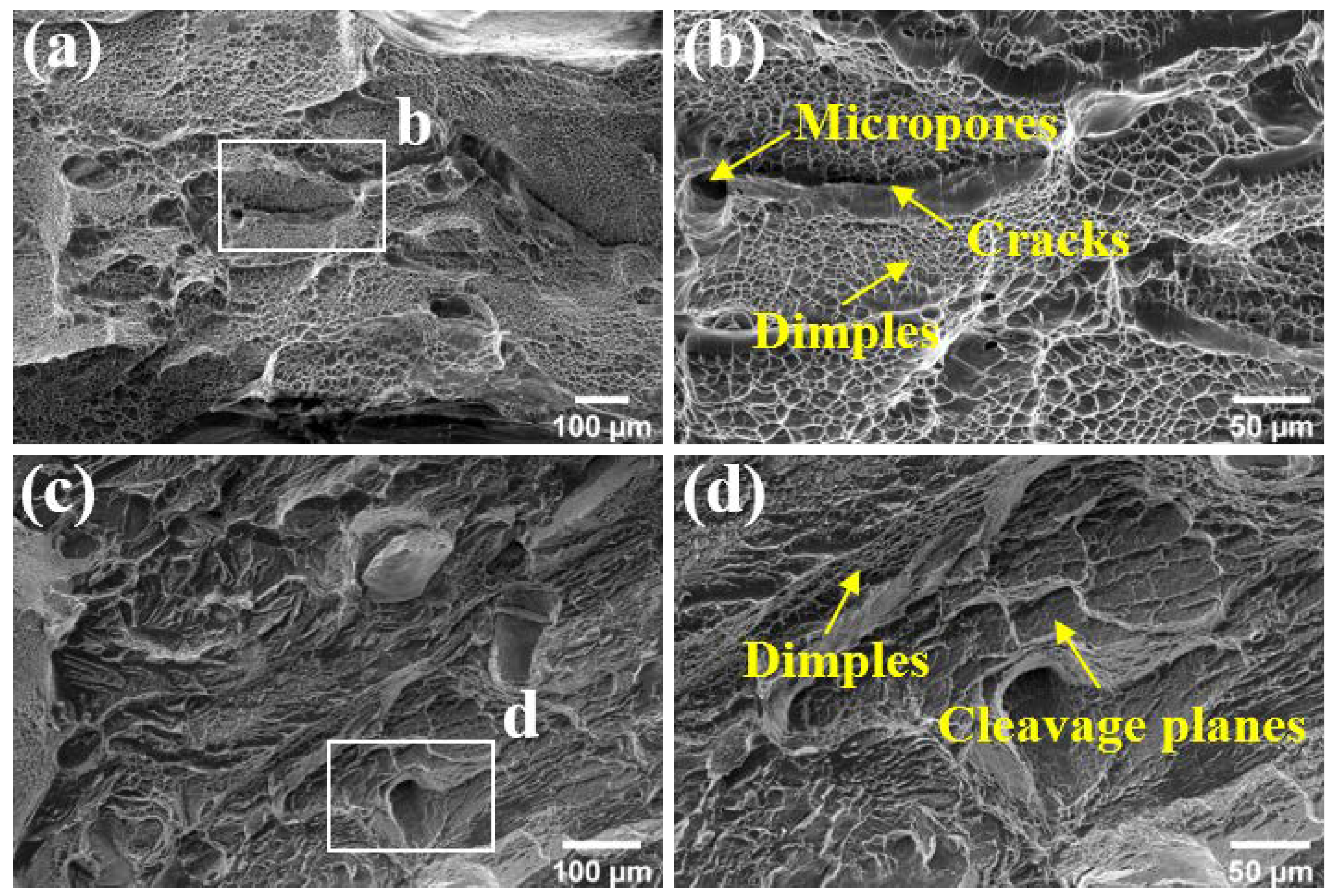
Tensile fracture morphology of both AW and PWAT joints is displayed in Figure 12. No welding porosity was observed in all fracture surfaces of tensile samples. There are a large number of dimples on the fracture surface in Figure 12a,b, which demonstrates the ductile fracture mode in AW samples. In addition, many micropores emerged among the dimples, and some cracks were generated with the coalescence of the micropores. After PWAT, the number of dimples decreased and some cleavage planes can be observed on the fracture surface in Figure 12c, which agree with the elongation reduction after PWAT. The localized dimples and cleavage planes on the fracture surface in Figure 12c,d indicate a mixed mode of PWAT samples.
4. Conclusions
In this study, the microstructure and mechanical properties of electron beam welded Ti-4Al-5Mo-5V-5Cr-1Nb (Ti-45551) alloy have been studied in both AW and PWAT conditions. According to our investigation, the following conclusions could be drawn.
(1) The EBW joint of Ti-45551 alloy was divided into FZ, Near-HAZ, Far-HAZ, and BM. The formation of α’ martensite or α phase was inhibited in FZ and Near-HAZ by the rapid cooling rate during electron beam welding and high Moeq value.
(2) After PWAT, small αs precipitated in the prior β matrix in the FZ and HAZ. The size (S) of the αs precipitation in different zones follows the order of SFar-HAZ < SFZ ≈ SNear-HAZ < SBM.
(3) The microhardness of the weldment presented a nonuniform distribution. In AW condition, there is a minimum microhardness in FZ and Near-HAZ, and the microhardness increased gradually to that of BM. PWAT led to a significant increase in the value of microhardness in FZ and HAZ. The microhardness of the Far-HAZ is the highest, reaching about 463 HV, and the microhardness of the FZ and the Near-HAZ is about 445 HV. While for the BM, the microhardness had barely changed.
(4) The as-welded joint exhibited poor strength (yield strength, 778 MPa) because the α phase was transformed into the β phase in the FZ and HAZ. Through PWAT, the yield strength was improved to 1254 MPa. Tensile fracture morphology indicated ductile fracture and mixed fracture occurred in the AW joint and in the PWAT joint, respectively.
Author Contributions
Investigation, X.Z. and M.T.; Formal analysis, X.Z.; Data curation, M.T.; writing-original draft preparation, X.Z. and M.T.; methodology, M.T.; supervision, B.C. and J.L.; funding acquisition, B.C. and J.L; writing-review and editing, B.C. and J.W. All authors have read and agreed to the published version of the manuscript.
Funding
This work was financially supported by the National Key Research and Development Program of China (2021YFB3702605) and the Research Fund of the State Key Laboratory of Solidification Processing (NPU), China (Grant No. 2022-QZ-02).
Institutional Review Board Statement
Not applicable.
Informed Consent Statement
Not applicable.
Data Availability Statement
Not applicable.
Acknowledgments
The authors acknowledge the State Key Laboratory of Solidification Processing.
Conflicts of Interest
The authors declare no conflict of interest.
References
- Kolli, R.; Devaraj, A. A Review of Metastable Beta Titanium Alloys. Metals 2018, 8, 506. [Google Scholar] [CrossRef] [Green Version]
- Banerjee, D.; Williams, J.C. Perspectives on Titanium Science and Technology. Acta Mater. 2013, 61, 844–879. [Google Scholar] [CrossRef]
- Cotton, J.D.; Briggs, R.D.; Boyer, R.R.; Tamirisakandala, S.; Russo, P.; Shchetnikov, N.; Fanning, J.C. State of the Art in Beta Titanium Alloys for Airframe Applications. JOM 2015, 67, 1281–1303. [Google Scholar] [CrossRef] [Green Version]
- Junaid, M.; Cheema, T.A. Influence of welding process on the properties of dissimilar titanium alloy weldments: A review. JMST Adv. 2020, 2, 61–76. [Google Scholar] [CrossRef]
- Choudhury, B.; Chandrasekaran, M. Investigation on welding Characteristics of aerospace materials—A review. Mater. Today Proc. 2017, 4, 7519–7526. [Google Scholar] [CrossRef]
- Kaur, A.; Ribton, C.; Balachandran, W. Development of a novel approach for characterising electron beams and quality assurance of welds. J. Manuf. Process. 2016, 24, 217–224. [Google Scholar] [CrossRef]
- Mironov, S.; Zhang, Y.; Sato, Y.S.; Kokawa, H. Crystallography of transformed β microstructure in friction stir welded Ti–6Al–4V alloy. Scr. Mater. 2008, 59, 511–514. [Google Scholar] [CrossRef]
- Pasang, T.; Amaya, J.M.S.; Tao, Y.; Amaya-Vazquez, M.R.; Botana, F.J.; Sabol, J.C.; Misiolek, W.Z.; Kamiya, O. Comparison of Ti-5Al-5V-5Mo-3Cr Welds Performed by Laser Beam, Electron Beam and Gas Tungsten Arc Welding. Procedia Eng. 2013, 63, 397–404. [Google Scholar] [CrossRef] [Green Version]
- Chamanfar, A.; Huang, M.-F.; Pasang, T.; Tsukamoto, M.; Misiolek, W.Z. Microstructure and mechanical properties of laser welded Ti–10V–2Fe–3Al (Ti1023) titanium alloy. J. Mater. Res. Technol. 2020, 9, 7721–7731. [Google Scholar] [CrossRef]
- Liu, H.; Wang, H.; Zhang, Z.; Huang, Z.; Liu, Y.; Wang, Q.; Chen, Q. Enhancing the mechanical properties of electron beam welded TC17 titanium alloy joint by post-weld heat treatment. J. Alloy. Compd. 2019, 810, 151937. [Google Scholar] [CrossRef]
- Węglowski, M.S.; Błacha, S.; Phillips, A. Electron beam welding—Techniques and trends—Review. Vacuum 2016, 130, 72–92. [Google Scholar] [CrossRef]
- Liu, H.; Song, J.; Wang, H.; Du, Y.; Yang, K.; Liu, Y.; Wang, Q.; Chen, Q. Heterogeneous microstructure and associated mechanical properties of thick electron beam welded Ti-5Al-2Sn-2Zr-4Mo-4Cr alloy joint. Mater. Sci. Eng. A 2021, 825, 141850. [Google Scholar] [CrossRef]
- Wu, M.; Xin, R.; Wang, Y.; Zhou, Y.; Wang, K.; Liu, Q. Microstructure, texture and mechanical properties of commercial high-purity thick titanium plates jointed by electron beam welding. Mater. Sci. Eng. A 2016, 677, 50–57. [Google Scholar] [CrossRef]
- Lu, W.; Li, X.; Lei, Y.; Shi, Y. Study on the mechanical heterogeneity of electron beam welded thick TC4-DT joints. Mater. Sci. Eng. A 2012, 540, 135–141. [Google Scholar] [CrossRef]
- Lu, W.; Shi, Y.; Lei, Y.; Li, X. Effect of electron beam welding on the microstructures and mechanical properties of thick TC4-DT alloy. Mater. Des. 2012, 34, 509–515. [Google Scholar] [CrossRef]
- Chen, S.; Huang, J.; Cheng, D.; Zhang, H.; Zhao, X. Superplastic deformation mechanism and mechanical behavior of a laser-welded Ti–6Al–4V alloy joint. Mater. Sci. Eng. A 2012, 541, 110–119. [Google Scholar] [CrossRef]
- Barreda, J.L.; Santamaría, F.; Azpiroz, X.; Irisarri, A.M.; Varona, J.M. Electron beam welded high thickness Ti6Al4V plates using filler metal of similar and different composition to the base plate. Vacuum 2001, 62, 143–150. [Google Scholar] [CrossRef]
- Oh, J.; Kim, N.J.; Lee, S.; Lee, E.W. Correlation of fatigue properties and microstructure in investment cast Ti-6Al-4V welds. Mater. Sci. Eng. A 2003, 340, 232–242. [Google Scholar] [CrossRef]
- Chen, Z.; Li, J.; Liu, J.; Wang, Q.; Liu, J.; Yang, R. Creep Behavior of Fusion Zone and Base Metal of the Electron Beam Weldments of a Near-alpha Titanium Alloy. J. Mater. Sci. Technol. 2010, 26, 564–571. [Google Scholar] [CrossRef]
- Zhang, K.; He, C.; Liu, D.; Yan, C.; Niu, H.; Yang, Z.; Bao, Y. Effect of heat input on microstructure and tensile properties of laser welded Ti–3Al–6Mo–2Fe–2Zr alloy joint. J. Mater. Res. Technol. 2022, 17, 1652–1661. [Google Scholar] [CrossRef]
- Lin, H.; Wang, L. Improved mechanical properties of Ti–15V–3Cr–3Sn–3Al alloy by electron beam welding process plus heat treatments and its microstructure evolution. Mater. Chem. Phys. 2011, 126, 891–897. [Google Scholar] [CrossRef]
- Long, J.; Zhang, L.; Ning, J.; Zhang, L.; Wang, X.; Li, S.; Suck-Joo, N. Effects of post-weld heat treatment on microstructures and properties of laser welded joints of new high-strength Ti-55531 alloy. J. Manuf. Process. 2021, 64, 1329–1335. [Google Scholar] [CrossRef]
- Fu, Q.; Yuan, W.; Xiang, W. Dynamic Softening Mechanisms and Microstructure Evolution of TB18 Titanium Alloy during Uniaxial Hot Deformation. Metals 2021, 11, 789. [Google Scholar] [CrossRef]
- Sabol, J.C.; Pasang, T.; Misiolek, W.Z.; Williams, J.C. Localized tensile strain distribution and metallurgy of electron beam welded Ti–5Al–5V–5Mo–3Cr titanium alloys. J. Mater. Processing Technol. 2012, 212, 2380–2385. [Google Scholar] [CrossRef]
- Gao, F.; Gao, Q.; Jiang, P.; Liu, Z.; Liao, Z. Microstructure and mechanical properties of Ti6321 alloy welded joint by EBW. Int. J. Lightweight Mater. Manuf. 2018, 1, 265–269. [Google Scholar] [CrossRef]
- Palanivel, R.; Dinaharan, I.; Laubscher, R.F. Microstructure evolution and mechanical characterization of Nd: YAG laser beam welded titanium tubes. Mater. Charact. 2017, 134, 225–235. [Google Scholar] [CrossRef]
- Weiss, I.; Semiatin, S. Thermomechanical processing of beta titanium alloys—An overview. Mater. Sci. Eng. A 1998, 243, 46–65. [Google Scholar] [CrossRef]
- Davis, R.; Flower, H.; West, D. Martensitic transformations in Ti-Mo alloys. J. Mater. Sci. 1979, 14, 712–722. [Google Scholar] [CrossRef]
- Wang, G.; Chen, Z.; Li, J.; Liu, J.; Wang, Q.; Yang, R. Microstructure and Mechanical Properties of Electron Beam Welded Titanium Alloy Ti-6246. J. Mater. Sci. Technol. 2018, 34, 570–576. [Google Scholar] [CrossRef]
- Yumak, N.; Aslantaş, K. Effect of Heat Treatment Procedure on Mechanical Properties of Ti-15V-3Al-3Sn-3Cr Metastable β Titanium Alloy. J. Mater. Eng. Perform. 2021, 30, 1066–1074. [Google Scholar] [CrossRef]
- Yadav, P.; Saxena, K.K. Effect of heat-treatment on microstructure and mechanical properties of Ti alloys: An overview. Mater. Today Proc. 2020, 26, 2546–2557. [Google Scholar] [CrossRef]
- Liu, C.; Wang, H.; Tian, X.; Tang, H.; Liu, D. Microstructure and tensile properties of laser melting deposited Ti-5Al-5Mo-5V-Cr-Fe near β titanium alloy. Mater. Sci. Eng. A 2013, 586, 323–329. [Google Scholar] [CrossRef]
- He, B.; Tian, X.; Cheng, X.; Li, J.; Wang, H. Effect of weld repair on microstructure and mechanical properties of laser additive manufactured Ti-55511 alloy. Mater. Des. 2017, 119, 437–445. [Google Scholar] [CrossRef]
Figure 1.
Microstructure of as-received material Ti-45551: (a) low magnification; and (b) high magnification.
Figure 1.
Microstructure of as-received material Ti-45551: (a) low magnification; and (b) high magnification.
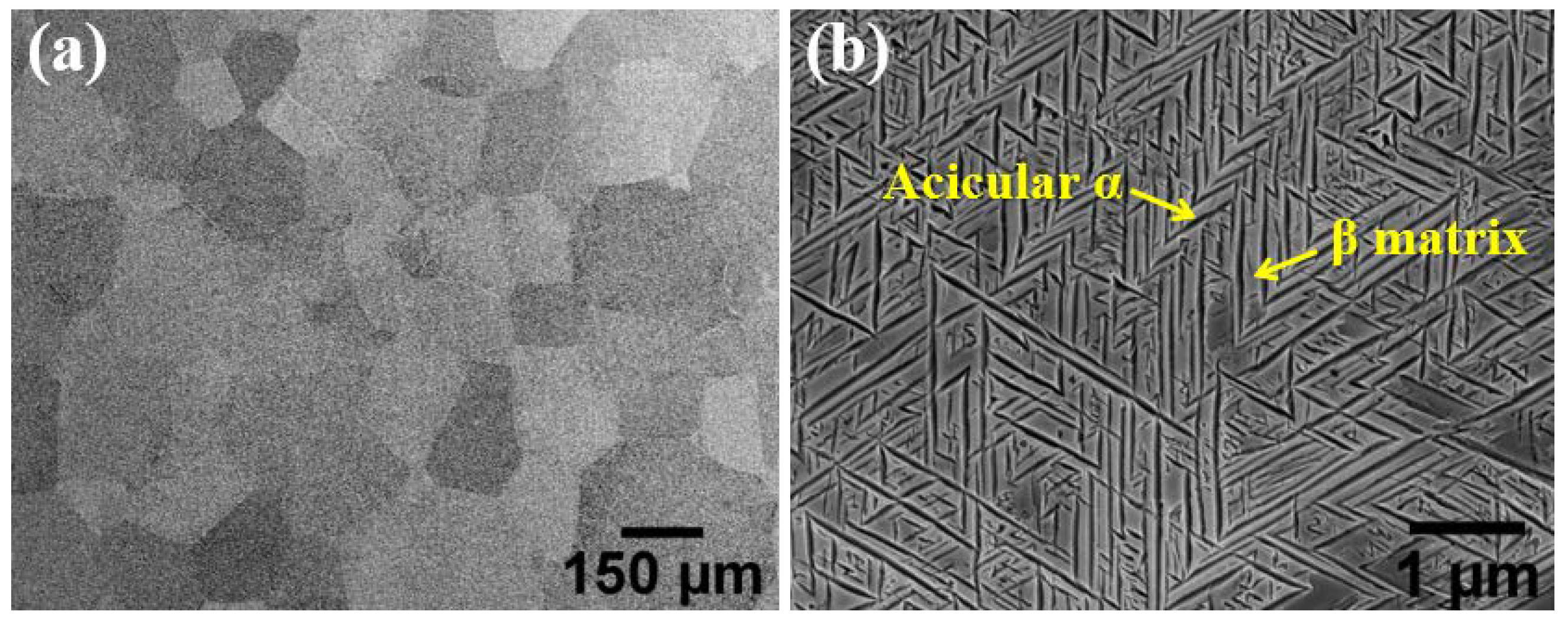
Figure 2.
Schematic diagram of EBW process of Ti-45551 alloy and the sampling position of the tensile samples.
Figure 2.
Schematic diagram of EBW process of Ti-45551 alloy and the sampling position of the tensile samples.
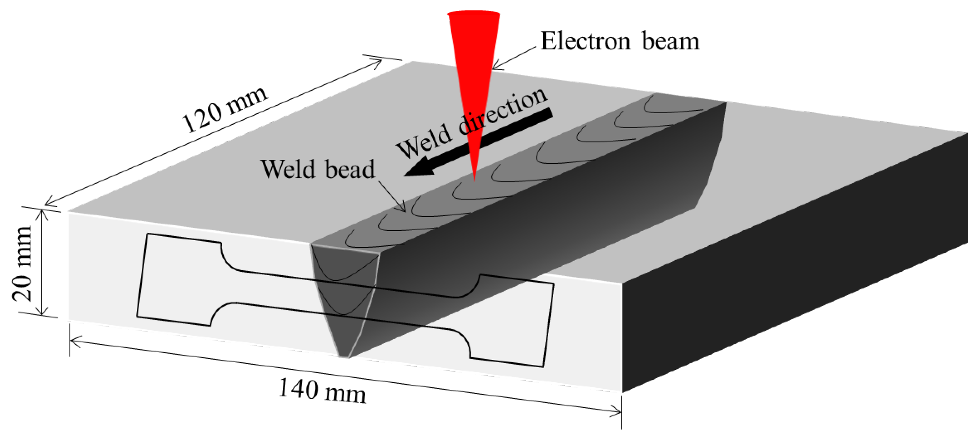
Figure 3.
The geometry size of the tensile sample, unit: mm.
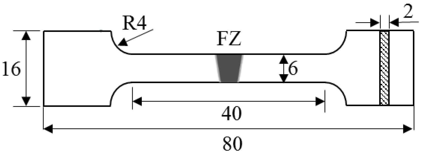
Figure 4.
Macroscopic morphology of butt joint: (a) top surface; (b) bottom surface; and (c) cross-section.
Figure 4.
Macroscopic morphology of butt joint: (a) top surface; (b) bottom surface; and (c) cross-section.
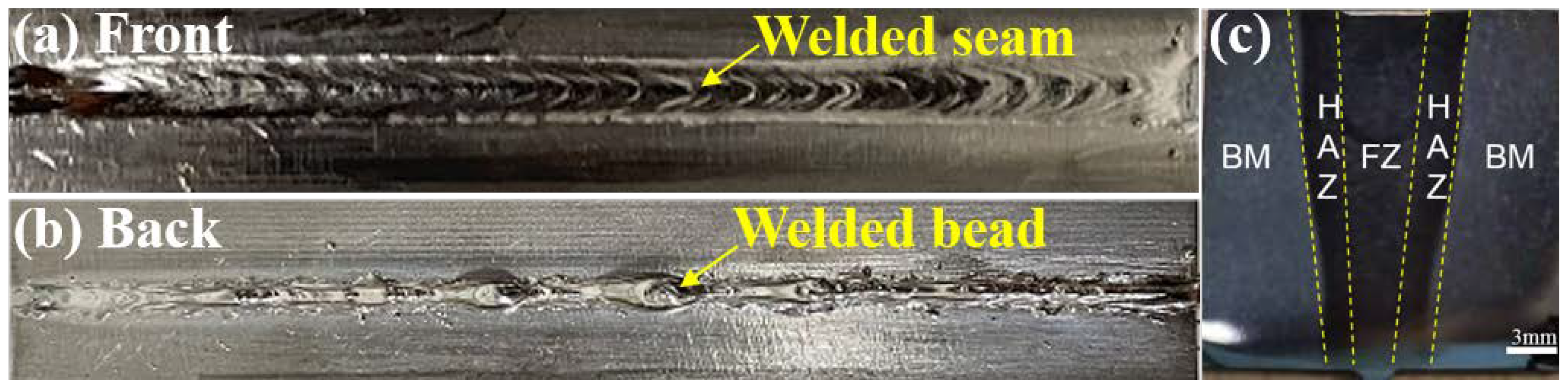
Figure 5.
Photomicrograph (OM) of the Ti-45551 alloy weld cross-section.

Figure 6.
XRD patterns of as-welded BM and FZ.

Figure 7.
Microstructure in a different zone of the as-welded joint: (a) FZ; (b) Near-HAZ; (c) Far-HAZ; and (d) BM.
Figure 7.
Microstructure in a different zone of the as-welded joint: (a) FZ; (b) Near-HAZ; (c) Far-HAZ; and (d) BM.
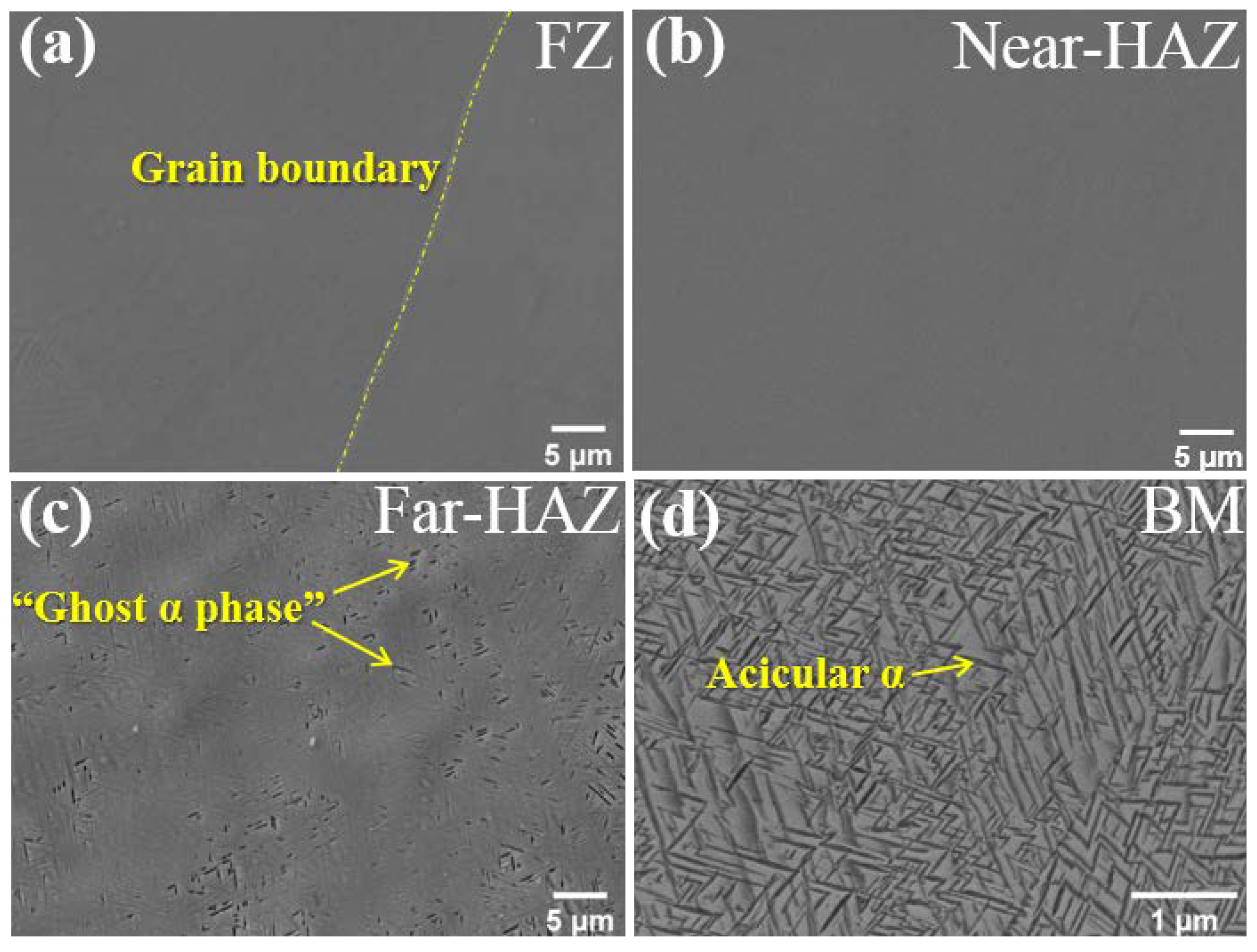
Figure 8.
The phase diagram of titanium alloys.
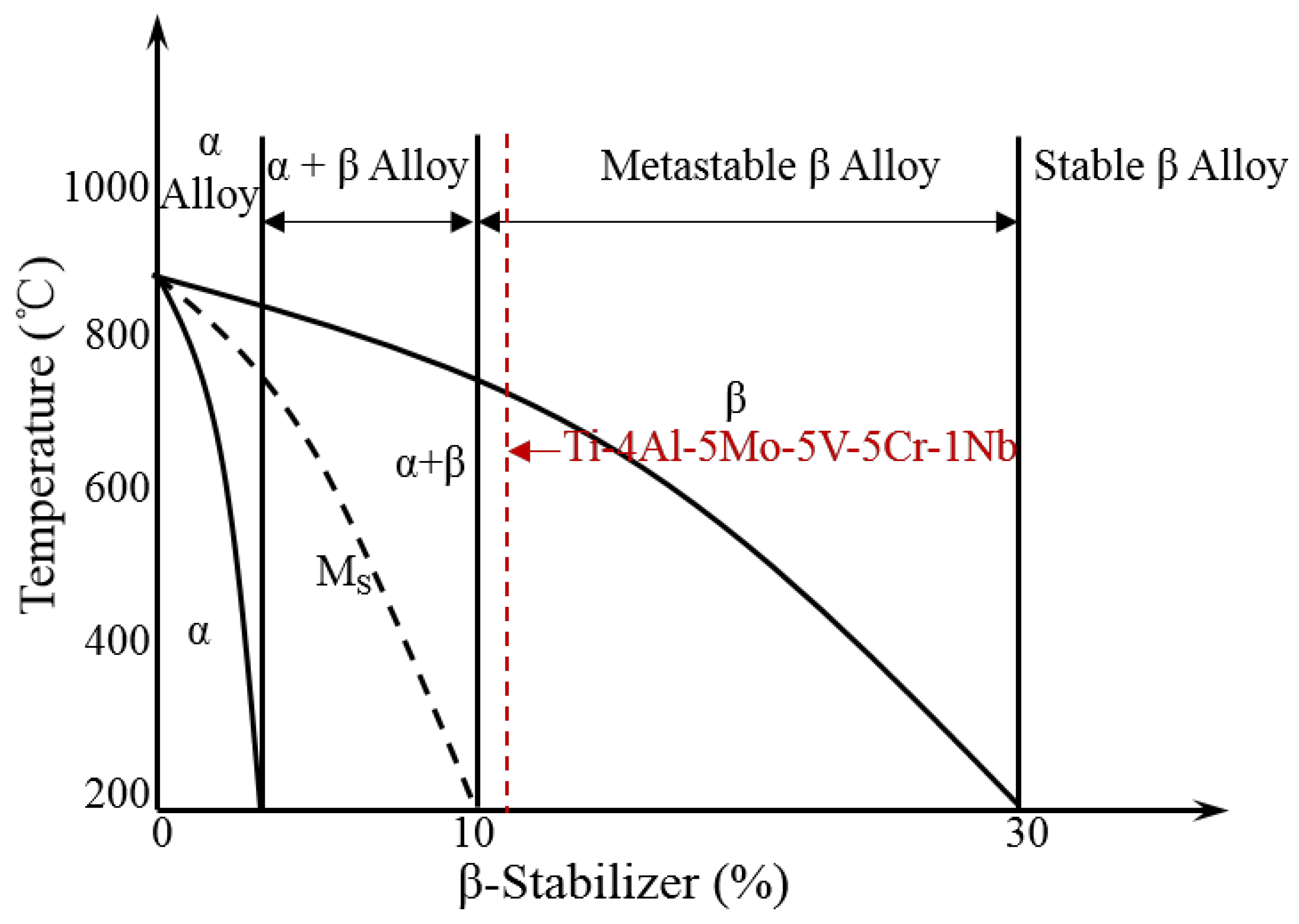
Figure 9.
Microstructure of weld joint in PWAT condition: (a) FZ; (b) Near-HAZ; (c) Far-HAZ; and (d) FZ.
Figure 9.
Microstructure of weld joint in PWAT condition: (a) FZ; (b) Near-HAZ; (c) Far-HAZ; and (d) FZ.

Figure 10.
The microhardness of weld joint in AW and PWAT conditions.

Figure 11.
Typical stress–strain curves of different joints.
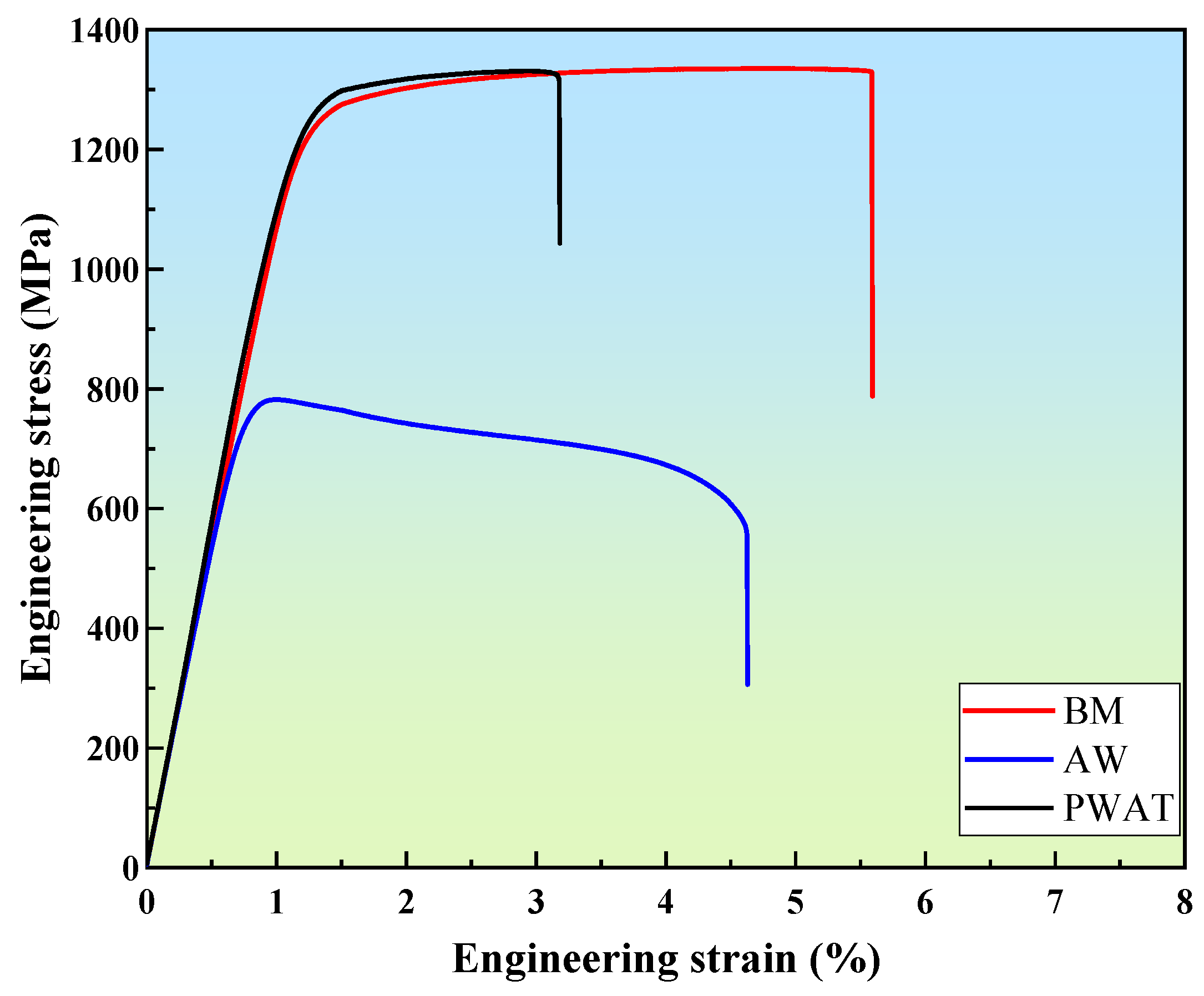
Figure 12.
Tensile fracture morphology of weld joints: (a,b) AW; and (c,d) PWAT.

Table 1.
Chemical composition of as-received material Ti-45551 (wt.%).
| Element | Al | Mo | Cr | V | Nb | O | N | H | Ti |
|---|---|---|---|---|---|---|---|---|---|
| wt.% | 4.21 | 5.15 | 5.35 | 4.95 | 1.31 | 0.09 | 0.03 | 0.0033 | Bal. |
Table 2.
Summary of mechanical properties for different conditions.
| Conditions | YS (MPa) | UTS (MPa) | El. (%) | Failure Location |
|---|---|---|---|---|
| As-received | 1250 | 1335 | 5.6 | - |
| As-weld | 778 | 782 | 4.6 | FZ |
| PWAT | 1254 | 1331 | 3.1 | FZ |
Publisher’s Note: MDPI stays neutral with regard to jurisdictional claims in published maps and institutional affiliations. |
© 2022 by the authors. Licensee MDPI, Basel, Switzerland. This article is an open access article distributed under the terms and conditions of the Creative Commons Attribution (CC BY) license (https://creativecommons.org/licenses/by/4.0/).
Share and Cite
MDPI and ACS Style
Zhang, X.; Li, J.; Tao, M.; Wan, J.; Chen, B. Electron Beam Welding and Post Heat Treatment of a New Near-Beta High-Strength Ti-4Al-5Mo-5V-5Cr-1Nb Alloy. Metals 2022, 12, 1396. https://doi.org/10.3390/met12081396
AMA Style
Zhang X, Li J, Tao M, Wan J, Chen B. Electron Beam Welding and Post Heat Treatment of a New Near-Beta High-Strength Ti-4Al-5Mo-5V-5Cr-1Nb Alloy. Metals. 2022; 12(8):1396. https://doi.org/10.3390/met12081396
Chicago/Turabian StyleZhang, Xinquan, Jinshan Li, Manfei Tao, Jie Wan, and Biao Chen. 2022. "Electron Beam Welding and Post Heat Treatment of a New Near-Beta High-Strength Ti-4Al-5Mo-5V-5Cr-1Nb Alloy" Metals 12, no. 8: 1396. https://doi.org/10.3390/met12081396
Note that from the first issue of 2016, this journal uses article numbers instead of page numbers. See further details here.