
Finite Element Analysis and Validation of Segments C2-C7 of the Cervical Spine

1
College of Material Science and Technology, Nanjing University of Aeronautics and Astronautics, Nanjing 211106, China
2
Faculty of Mechanical and Material Engineering, Jiangsu Provincial Engineering Research Center for Biomaterials and Advanced Medical Devices, Huaiyin Institute of Technology, Huai’an 223003, China
*
Author to whom correspondence should be addressed.
Metals 2022, 12(12), 2056; https://doi.org/10.3390/met12122056
Submission received: 8 October 2022
/
Revised: 20 November 2022
/
Accepted: 25 November 2022
/
Published: 29 November 2022
(This article belongs to the Special Issue Advances in Stability of Metallic Implants)
Abstract
:As an important part of the human spine, the cervical spine has a complex structure and easily suffers from diseases. Analysis of the biomechanical mechanism of cervical spine structure using the finite element model is not only helpful for the diagnosis, treatment and prevention of cervical spine diseases but also has positive significance for the performance evaluation of cervical spine implants. In this paper, a method of establishing a cervical C2-C7 finite element model based on CT image data is studied. Through the preprocessing of cervical CT images, the C2-C7 three-dimensional finite element model of the cervical spine was established. The pure moment loads of 0.33 Nm, 0.5 Nm, 1 Nm, 1.5 Nm and 2 Nm were applied to simulate flexion/extension, and the moment of 1 Nm was used to simulate the left and right lateral bending and axial rotation of the cervical spine. The relative range of motion (ROM) between each vertebral body was calculated. At the same time, the stress on some segments under axial load was analyzed. The results were basically consistent with the experimental data of in vitro studies, which verified the validity of the model.
1. Introduction
The spine consists of the cervical vertebra, the thoracic vertebra, the lumbar vertebra and the sacrum. With its more complicated structure and larger ranges of motion compared to the thoracic vertebra and lumbar vertebra, the cervical vertebra plays a significant role in people’s daily lives. With the development of modern industry, the change in people’s work and lifestyle as well as the population aging, the incidence of cervical spondylosis has shown a rising trend year by year, which has brought great inconvenience to people’s daily lives. The prevention of cervical spondylosis and the improvement of treatment effectiveness have always been goals to strive for. The statistics of the motion tendency and the stress distribution of the cervical vertebra under different loads can be obtained through experiments in vivo and in vitro [1,2,3,4,5]. However, their applications are subject to certain restrictions due to the exceptionality of the human body, resulting in high cost, high risk, and specificity of experimental results. Belytschko et al. [6] and other researchers established the two-dimensional finite element model early in 1974 to evaluate the material attribute of the intervertebral disc and to predict its mechanical behavior under axial loads. However, due to the complex anatomical structure of the cervical vertebra, the finite element model developed slowly. Not until the 1990s did Bozic et al. [7] and Teo et al. [8], along with their teams, accomplish the three-dimensional reconstruction of the vertebral body using CT data and a three-dimensional digitizer. Based on this, the more lifelike and fine-mesh finite element model of the single vertebra was constructed, although there was still a great discrepancy between the model and the actual conditions, especially in terms of less consideration given to soft tissue and the single material property. Since then, with the development of computer software, hardware as well as the advancement of medical imaging technology, the finite element model of the cervical spine has also developed from an initially single-level model to a multi-level one and has included the entire cervical level [9,10,11,12,13]. The material model of intervertebral disc and ligament has also been further refined.
The FEM of the cervical spine can be divided into dynamic analysis and static analysis depending on the application scenario. With respect to dynamic analysis of the cervical spine, Cronin’s project team [11,14,15] from Canada performed in-depth research covering 3D modeling, meshing, and material model constitution, and also analyzed the mechanism of cervical spine soft tissue injury in frequent traffic accidents. Mustafy et al. [16] introduced time and rate-dependent material laws in the finite element model of segments C2-C3 to simulate the mechanism of cervical ligament injury under complex loading. Meyer et al. [17] simulated the forces and moments of the cervical spine segments in cases of a frontal impact with an experimentally validated finite element model. As for static analysis, Zhang et al. [18] built a finite element model of the complete cervical spine from C0 to C7 and compared the model with experimental results in terms of flexion/extension, lateral bending and axial rotation under a load of 1.0 Nm. Limited by the conditions back then, the material model settings were relatively simple, producing larger differences from the experimental results in terms of lateral bending. Kallemeyn et al. [19] built a finite element model of segments C2-C7 based on multiblock meshing techniques and specific specimen data; the material properties of the model were then calibrated using the experimental results of the specimens. Erbulut et al. [20] also built a finite element model of C2-T1 based on the multiblock meshing technique to study the effect of soft tissue on cervical spine stability. To promote the exchange of scientific research on finite element models of the cervical spine, Herron et al. [21] built the finite element models of the cervical spine of females at different ages. They noticed that despite the same material properties and boundary conditions, their biomechanical properties differed markedly, and the authors considered that was because of differences in the morphology of the models.
With the improvement of the finite element model, its applications in medical engineering widen increasingly. By creating finite element models of different cervical spine surgeries, the influence of different surgical methods on range of motion and intervertebral disc stress can be evaluated [22,23,24]. Nishida [25] established three different models of cervical soft tissue injury and analyzed the risk factors of cervical instability. In addition, the cervical spine finite element model can also be used to analyze the biomechanics of implanted medical devices and evaluate their performance [26,27]. In the field of traditional Chinese medicine, some researchers have also explored the application of finite element model in the treatment of cervical spondylosis with traditional traction and other conservative methods [28]. With the increasingly wide applications of the finite element method in spine research, it has become urgent to find a quick and convenient establishment of the finite element model for the spine. Targeting the cervical segments C2-C7, this paper is meant to provide a feasible solution for the finite element analysis of the complex spine structure based on the strong mesh processing function of the general pre-processing software and the analysis function of the professional finite element software.
2. Materials and Methods
2.1. Finite Element Model Establishment
The experimental data were obtained from the medical image database. The CT layer thickness was 0.625 mm, and the image resolution was 512 × 512 pixels, including the entire cervical spine. Firstly, the CT data were imported into medical image processing software, and the soft tissue images around the bone were removed using layer-by-layer segmentation, and the CT images of each tomography were edited and processed to complete the three-dimensional reconstruction of the cervical vertebra bone model. The model was imported into the reverse engineering software Geomagic 2012 (3D Systems Corporation, Rock Hill, SC, USA) in STL format, and the NURBS surface of the vertebral body was fitted by its functions, such as accurate surface, which was saved as an IGES file. The IGES file of the vertebral body was imported into the general finite element preprocessing software Hypermesh 13.0 (Altair Engineering Inc, Troy, MI, USA) to complete the partition of the vertebral body mesh. Based on the physiological and anatomical structure of cervical spine vertebra, the vertebral body is divided into the cortical bone, cancellous bone, endplate and posterior structure of the vertebral body. The correct choice of element for a particular simulation is vital if accurate results are to be obtained at a reasonable cost. Due to the complex structure of the vertebral body, it is difficult to mesh completely with hexahedrons. Therefore, tetrahedral elements may be necessary; the cancellous bone and the posterior part of the vertebral body are divided into 4-node tetrahedral elements, and the cortical bone and endplate are divided into 3-node shell elements. Components of each vertebra are show in Figure 1.
An intervertebral disc is a sealed body located between two adjacent vertebrae of the human spine and is composed of cartilaginous endplate, peripheral annulus fibrosus and central nucleus pulposus, in which the volume of nucleus pulposus accounts for about 44% of the volume of the whole intervertebral disc [16]. The annulus fibrosus adopts a four-layer hexahedral element from the outside to the inside, and a truss element with a cross-angle close to ±35° and only tension is used to simulate the annulus fibrosus fiber [29].
The ligaments were simulated using nonlinear connecting elements, which can simulate the nonlinear stretching process of ligaments based on the force-displacement data provided by the experimental data. This includes the anterior longitudinal ligament (ALL), posterior longitudinal ligament (PLL), ligamentum flavum, (FL), interspinous ligament (ISL) and capsular ligament (CL). The starting and ending positions of ligaments and the number of elements were determined according to the anatomical structure of cervical spine and related literature [30,31]. The contact behavior of the posterior facet joint was defined by using contact pairs with Abaqus 6.14 (Dassault Systèmes Simulia Corp., Providence, RI, USA). The finite-sliding, surface-to-surface formulation was used in this model, and the relationship between contact stress and clearance was set as an exponential. The whole finite element model included 75,648 nodes and 319,184 elements. The detailed data of element types and material properties are shown in Table 1, and the finite element model of segments C2-C7 is shown in Figure 2a. The detailed model of segments C5-C6 and the intervertebral disc model are shown in Figure 2b,c, respectively. After completing the finite element model using Hypermesh 13.0 software, the model was imported into Abaqus software. The solution and post-processing were completed with Abaqus software.
2.2. Load and Boundary Conditions
Binding constraints were set between the upper and lower surfaces of the intervertebral disc and the corresponding vertebral surfaces (endplates). Constraints were set on the 6 degrees of freedom of all nodes of the lower endplate of the C7 vertebral body. In order to compare with the results of previous in vitro experiments and verify the validity of the finite element model, the pure moment loads of 0.33 Nm, 0.5 Nm, 1 Nm, 1.5 Nm and 2 Nm were applied for flexion (+) and extension (−), and 1 Nm was applied for the left and right lateral bending and axial rotation. These loads also ensured that the range of motion of the cervical spine was within the normal range. The range of motion and intervertebral disc stress on each segment of the cervical spine under different load conditions were analyzed using finite element analysis.
3. Results
3.1. Range of Motion
By applying different flexion/extension loads to the model, the nonlinearity of cervical spine motion is well simulated. The range of motion during flexion is slightly larger than that during extension, which may be related to the effects of the facet joint on cervical spine motion during extension. In different segments, the results are shown in Figure 3. In flexion loading, the results of segments C2-C3, C4-C5 and C6-C7 were close to the values of Wheeldon et al.’s [3] and Camacho et al.’s [38] experimental data. In segments C3-C4 and C5-C6, the present study’s results were close to the value of Camacho et al.’s [38] but stiffer than those of Wheeldon et al. [3] and Nightingale et al. [2], especially in segments C5-C6. In segments C6-C7, the results of the model were more flexible than those of Nightingale et al. [4] and Camacho et al. [38]. During the extension, the range of motion under different load conditions was close to the results of Wheeldon et al. [3], except in segments C2-C3, which was reduced by about 36% in comparison.
In Figure 4 and Figure 5, the range of motion of lateral bending and axial rotation of different segments were compared with those of Panjabi et al. [1] and Zhang et al. [18]. In lateral bending, the results of segments C3-C4 and C4-C5 were smaller, different by about one standard deviation compared to those of Panjabi et al. [1]. In the rest of the segments (C2-C3, C5-C6 and C6-C7), the results and the mean value were in good agreement with the experimental data. In axial rotation, the mean value and the ranges of motion of segments C3-C4 and C5-C6 were close to the results of Panjabi et al. [1]. In segments C2-C3 and C6-C7, the finite element model was more flexible.
3.2. Intervertebral Disc Stress
By applying different axial loads to simulate intervertebral disc compression, the intervertebral disc stress level and variation trend of segments C4-C5 are consistent with the relevant experimental results [39], as shown in Figure 6. In addition, in the process of simulating forward flexion/extension movement with a preloaded 10 N axial load, the stresses on the C3-C4 and C5-C6 intervertebral discs were smaller those the experimental results of Pospiech et al. [40]. As shown in Figure 7, the results of the finite element model were reduced by about 46% in segments C3-C4 and by about 35% in segments C5-C6 in comparison.
4. Discussion
By processing CT images to generate contour data of the vertebral body, the intervertebral disc was accomplished using general software to ensure the accuracy of the model and convenience for follow-up processing. This opens up a new way for the finite element analysis of complex structures. The selection of materials was further refined according to the current references and the actual conditions. For example, the past finite element model usually used uncompressed truss elements to simulate ligament tissues while the ligament shows a strong nonlinearity in the process of stretching [31,41]. Therefore, the nonlinear lconnecting element is used in this model to better present that feature. In addition, the construction of the intervertebral disc model also plays a key role in the whole finite element analysis. In this model, different hyperelastic materials were adopted to simulate the nucleus pulposus and the base of annulus fibrosus with five diagonally intersected layers of tensile-stressed truss elements from outside to inside with a ±35° distribution [29], which guarantees the simulation of the intervertebral disc in both shape and structure.
Due to the restrictions on the in vitro experiments, our research group conducted an in-depth analysis of the relevant published in vitro experiments to verify the effectiveness of the model. A couple well-accepted classic experiments were selected for reference. Generally speaking, the range of motion and the variation trend resulting from the established finite element model of segments C2-C7 of the cervical vertebra are consistent with the results of the in vitro experiments in terms of flexion/extension, lateral bending and axial rotation. In the process of flexion, the finite element model analysis reproduces the nonlinearity of cervical spine movement while the results of different segments fall in the range of the different experimental results [2,3,4,38]. In the process of extension, the finite element model shows a sound coherence with the experimental results of Wheeldon [3] and Nightingale [2,4] in segments C3-C4, C4-C5 and C5-C6, with a generally higher stiffness. In segments C2-C3 and C6-C7, the stiffnesses of the finite element model is higher than those of the in vitro experiments. Although the results were within the range of a standard deviation of the experimental data, the range of motion of segments C2-C3 was reduced by 36% compared to the experimental mean of Wheeldon et al. [3] and by about 50% compared to the experimental mean of Camacho et al. [38]. We hold that the differences may be due to the thickness and size of the posterior articular cartilage and the direction of contact during extension. Relevant studies also showed that the orientation of the facet and the settings of the contact parameters could lead to different analysis results [36,37]. In terms of anatomical structure, the articular cartilage in C2-C3 and C6-C7 was thicker than those in the other segments [42], of which the difference was not fully reflected in the finite element modeling. In addition, to facilitate the finite element analysis (FEA) solution, a large contact range is preferred when setting the articular contact surface, which could be another cause for such results. In the process of lateral bending, the results of segments C2-C3 and C5-C6 meet the experimental results [1], whereas those of segments C3-C5 are smaller and those of segments C6-C7 are larger. Moreover, the ranges of motion of all segments are larger than the results of the finite element analysis from Zhang [18]. In the analysis of axial rotational movement, the results of this model are in correspondence with both the in vitro experiment from Panjabi [1] and the finite element analysis from Zhang [18]. It is also found in the analysis that the direction in which a moment of force is applied has a greater impact on the results of lateral bending and axial rotation than those of flexion and extension. Therefore, the load applied in the model verification is consistent with those of the in vitro experiments.
To further verify the effectiveness of the model, this research also targets intervertebral disc stress. However, as the cervical vertebra is smaller and more complicated than the lumbar vertebra in structure, this research only makes comparisons with the experimental results in terms of intervertebral disc stress on partial segments under two different loads. The results show that under the axial compressive load, the intervertebral disc stress level and the trend of segments C4-C5 correspond with the experimental results. The intervertebral disc stress on segments C3-C4 and C5-C6 under a flexion/extension moment of 0.5 Nm with a pre-compression load of 10 N is lower than the average of the experimental value. The intervertebral disc is an early and easily degenerated and aged organ in the human body. In Pospiech et al.’s [40] experiment, the mean age of the selected specimens was 44.3 (27 to 64); in the FEA, the material model could not fully simulate the actual situation, which might be the main cause for the differences.
5. Conclusions
The three-dimensional finite element model of segments C2-C7 is proved to be convenient and feasible through the comparison of the model with the in vitro experiments under different load conditions. The model analysis has shown coherence with the results of the in vitro experiments in terms of either the range of motion or intervertebral disc stress. The model can be applied to analyze the biomechanical characteristics of the cervical spine, providing a possibility for the study of the mechanism for cervical spine disease as well as prosthesis implantation performance. However, due to the complex structure of cervical spine, there are large deformations, material nonlinearity and contact nonlinearity in the process of analysis. Although this model tries to make the setting of the shape and material properties close to reality, some simplifications are inevitably adopted. The influence of muscles, blood vessels and the spinal cord was ignored in the process of establishing the finite element model, which still needs to be further improved in future analysis.
Author Contributions
X.C., T.W. and C.P. contributed substantially to the conception and design of the experiments. X.C. conducted the experiments and wrote the manuscript. T.W. and C.P. conducted the data analyses. All authors have read and agreed to the published version of the manuscript.
Funding
This research was funded by the International Science and Technology Cooperation Programme (2018YFE0194100), the National Natural Science Foundation of China (31870952) and the Priority Academic Program Development of Jiangsu Higher Education Institutions.
Institutional Review Board Statement
Not applicable.
Informed Consent Statement
Not applicable.
Data Availability Statement
The original contributions presented in this study are included in the article; further inquiries can be directed to the corresponding author.
Conflicts of Interest
The authors declare no conflict of interest.
References
- Panjabi, M.; Crisco, J.J.; Vasavada, A.; Oda, T.; Cholewicki, J.; Nibu, K.; Shin, E. Mechanical properties of the human cervical spine as shown by three-dimensional load-displacement curves. Spine 2001, 26, 2692–2700. [Google Scholar] [CrossRef]
- Nightingale, R.W.; Winkelstein, B.A.; Knaub, K.E.; Richardson, W.J.; Luck, J.F.; Myers, B.S. Comparative strengths and structural properties of the upper and lower cervical spine in flexion and extension. J. Biomech. 2002, 35, 725–732. [Google Scholar] [CrossRef]
- Wheeldon, J.A.; Pintar, F.A.; Knowles, S.; Yoganandan, N. Experimental flexion/extension data corridors for validation of finite element models of the young, normal cervical spine. J. Biomech. 2006, 39, 375–380. [Google Scholar] [CrossRef]
- Nightingale, R.W.; Carol Chancey, V.; Ottaviano, D.; Luck, J.F.; Tran, L.; Prange, M.; Myers, B.S. Flexion and extension structural properties and strengths for male cervical spine segments. J. Biomech. 2007, 40, 535–542. [Google Scholar] [CrossRef]
- Liu, Q.; Guo, Q.; Yang, J.; Zhang, P.; Xu, T.; Cheng, X.; Chen, J.; Guan, H.; Ni, B. Subaxial Cervical Intradiscal Pressure and Segmental Kinematics Following Atlantoaxial Fixation in Different Angles. World Neurosurg. 2016, 87, 521–528. [Google Scholar] [CrossRef]
- Belytschko, T.; Kulak, R.F.; Schultz, A.B.; Galante, J.O. Finite element stress analysis of an intervertebral disc. J. Biomech. 1974, 7, 277. [Google Scholar] [CrossRef]
- Bozic, K.J.; Keyak, J.H.; Skinner, H.B.; Bueff, H.U.; Bradford, D.S. Three-dimensional finite element modeling of a cervical vertebra: An investigation of burst fracture mechanism. J. Spinal Disord. 1994, 7, 102–110. [Google Scholar] [CrossRef]
- Teo, E.C.; Paul, J.P.; Evans, J.H. Finite element stress analysis of a cadaver second cervical vertebra. Med. Biol. Eng. Comput. 1994, 32, 236. [Google Scholar]
- Teo, E.C.; Ng, H.W. Evaluation of the Role of Ligaments, Facets and Disc Nucleus in Lower Cervical Spine Under Compression and Sagittal Moments Using Finite Element Method. Med. Eng. Phys. 2001, 23, 155–164. [Google Scholar] [CrossRef]
- Del Palomar, A.P.; Calvo, B.; Doblaré, M. An Accurate Finite Element Model of the Cervical Spine Under Quasi-Static Loading. J. Biomech. 2008, 41, 523–531. [Google Scholar] [CrossRef]
- Panzer, M.B.; Fice, J.B.; Cronin, D.S. Cervical Spine Response in Frontal Crash. Med. Eng. Phys. 2011, 33, 1147–1159. [Google Scholar] [CrossRef] [PubMed]
- Oxland, T.R. Fundamental Biomechanics of the Spine—What we Have Learned in the Past 25 Years and Future Directions. J. Biomech. 2016, 49, 817–832. [Google Scholar] [CrossRef]
- Kim, Y.H.; Khuyagbaatar, B.; Kim, K. Recent Advances in Finite Element Modeling of the Human Cervical Spine. J. Mech. Sci. Technol. 2018, 32, 1–10. [Google Scholar] [CrossRef]
- DeWit, J.A.; Cronin, D.S. Cervical Spine Segment Finite Element Model for Traumatic Injury Prediction. J. Mech. Behav. Biomed. 2012, 10, 138–150. [Google Scholar] [CrossRef] [PubMed]
- Cronin, D.S. Finite Element Modeling of Potential Cervical Spine Pain Sources in Neutral Position Low Speed Rear Impact. J. Mech. Behav. Biomed. 2014, 33, 55–66. [Google Scholar] [CrossRef] [PubMed]
- Mustafy, T.; Moglo, K.; Adeeb, S.; El-Rich, M. Injury Mechanisms of the Ligamentous Cervical C2-C3 Functional Spinal Unit to Complex Loading Modes: Finite Element Study. J. Mech. Behav. Biomed. 2016, 53, 384–396. [Google Scholar] [CrossRef] [PubMed]
- Meyer, F.; Humm, J.; Purushothaman, Y.; Willinger, R.; Pintar, F.A.; Yoganandan, N. Forces and Moments in Cervical Spinal Column Segments in Frontal Impacts Using Finite Element Modeling and Human Cadaver Tests. J. Mech. Behav. Biomed. 2019, 90, 681–688. [Google Scholar] [CrossRef]
- Zhang, Q.H.; Teo, E.C.; Ng, H.W.; Lee, V.S. Finite Element Analysis of Moment-Rotation Relationships for Human Cervical Spine. J. Biomech. 2006, 39, 189–193. [Google Scholar] [CrossRef]
- Kallemeyn, N.; Gandhi, A.; Kode, S.; Shivanna, K.; Smucker, J.; Grosland, N. Validation of a C2–C7 Cervical Spine Finite Element Model Using Specimen-Specific Flexibility Data. Med. Eng. Phys. 2010, 32, 482–489. [Google Scholar] [CrossRef]
- Erbulut, D.U.; Zafarparandeh, I.; Lazoglu, I.; Ozer, A.F. Application of an Asymmetric Finite Element Model of the C2-T1 Cervical Spine for Evaluating the Role of Soft Tissues in Stability. Med. Eng. Phys. 2014, 36, 915–921. [Google Scholar] [CrossRef] [PubMed]
- Herron, M.R.; Park, J.; Dailey, A.T.; Brockmeyer, D.L.; Ellis, B.J. Febio Finite Element Models of the Human Cervical Spine. J. Biomech. 2020, 113, 110077. [Google Scholar] [CrossRef] [PubMed]
- Hua, W.; Zhi, J.; Ke, W.; Wang, B.; Yang, S.; Li, L.; Yang, C. Adjacent Segment Biomechanical Changes After One- Or Two-Level Anterior Cervical Discectomy and Fusion Using Either a Zero-Profile Device or Cage Plus Plate: A Finite Element Analysis. Comput. Biol. Med. 2020, 120, 103760. [Google Scholar] [CrossRef] [PubMed]
- Chen, C.; Yuchi, C.X.; Gao, Z.; Ma, X.; Zhao, D.; Li, J.W.; Xu, B.; Zhang, C.Q.; Wang, Z.; Du, C.F.; et al. Comparative Analysis of the Biomechanics of the Adjacent Segments After Minimally Invasive Cervical Surgeries Versus Anterior Cervical Discectomy and Fusion: A Finite Element Study. J. Orthop. Transl. 2020, 23, 107–112. [Google Scholar] [CrossRef] [PubMed]
- Khalaf, K.; Nikkhoo, M. Comparative Biomechanical Analyses of Lower Cervical Spine Post Anterior Fusion Versus Intervertebral Disc Arthroplasty: A Geometrically Patient-Specific Poroelastic Finite Element Investigation. J. Orthop. Transl. 2022, 36, 33–43. [Google Scholar] [CrossRef]
- Nishida, N.; Tripathi, S.; Mumtaz, M.; Kelkar, A.; Kumaran, Y.; Sakai, T.; Goel, V.K. Soft Tissue Injury in Cervical Spine is a Risk Factor for Intersegmental Instability: A Finite Element Analysis. World Neurosurg. 2022, 164, e358–e366. [Google Scholar] [CrossRef]
- Yuan, W.; Zhang, H.; Zhou, X.; Wu, W.; Zhu, Y. The Influence of Artificial Cervical Disc Prosthesis Height on the Cervical Biomechanics: A Finite Element Study. World Neurosurg. 2018, 113, e490–e498. [Google Scholar] [CrossRef]
- Zhou, E.; Huang, H.; Zhao, Y.; Wang, L.; Fan, Y. The Effects of Titanium Mesh Cage Size on the Biomechanical Responses of Cervical Spine After Anterior Cervical Corpectomy and Fusion: A Finite Element Study. Clin. Biomech. 2022, 91, 105547. [Google Scholar] [CrossRef]
- Wang, K.; Wang, H.; Deng, Z.; Li, Z.; Zhan, H.; Niu, W. Cervical Traction Therapy with and without Neck Support: A Finite Element Analysis. Musculoskel. Sci. Prac. 2017, 28, 1–9. [Google Scholar] [CrossRef]
- Schmidt, H.; Heuer, F.; Drumm, J.; Klezl, Z.; Claes, L.; Wilke, H.J. Application of a calibration method provides more realistic results for a finite element model of a lumbar spinal segment. Clin. Biomech. 2007, 22, 377–384. [Google Scholar] [CrossRef]
- Panjabi, M.M. Cervical Spine Models for Biomechanical Research. Spine 1998, 23, 2684. [Google Scholar] [CrossRef]
- Yoganandan, N.; Kumaresan, S.; Pintar, F.A. Geometric and mechanical properties of human cervical spine ligaments. J. Biomech. Eng. 2000, 122, 623. [Google Scholar] [CrossRef] [PubMed]
- Ha, S.K. Finite element modeling of multi-level cervical spinal segments (c3–c6) and biomechanical analysis of an elastomer-type prosthetic disc. Med. Eng. Phys. 2006, 28, 534–541. [Google Scholar] [CrossRef]
- Kumaresan, S.; Yoganandan, N.; Pintar, F.A. Finite element modeling approaches of human cervical spine facet joint capsule. J. Biomech. 1998, 31, 371–376. [Google Scholar] [CrossRef] [PubMed]
- Li, Y.; Lewis, G. Influence of the constitutive material behavior model assigned to the annulus fibrosus and the nucleus pulposus on the biomechanical performance of a model of the cervical spine: A finite element analysis study. J. Mech. Med. Biol. 2010, 10, 151–166. [Google Scholar] [CrossRef]
- Ezquerro, F.; Vacas, F.G.; Postigo, S.; Prado, M.; Simón, A. Calibration of the finite element model of a lumbar functional spinal unit using an optimization technique based on differential evolution. Med. Eng. Phys. 2011, 33, 89–95. [Google Scholar] [CrossRef]
- Kim, H.; Chun, H.; Lee, H.; Kang, K.; Lee, C.; Chang, B.; Yeom, J.S. The biomechanical influence of the facet joint orientation and the facet tropism in the lumbar spine. Spine J. 2013, 13, 1301–1308. [Google Scholar] [CrossRef] [PubMed]
- Panzer, M.B.; Cronin, D.S. C4–c5 segment finite element model development, validation, and load-sharing investigation. J. Biomech. 2009, 42, 480–490. [Google Scholar] [CrossRef] [PubMed]
- Camacho, D.L.; Nightingale, R.W.; Robinette, J.J.; Vanguri, S.K.; Coates, D.J.; Myers, B.S. (Eds.) Experimental Flexibility Measurements for the Development of a Computational Head-Neck Model Validated for Near-Vertex Head Impact; SAE International: Warrendale, PA, USA, 1997. [Google Scholar]
- Womack, W.; Leahy, P.D.; Patel, V.V.; Puttlitz, C.M. Finite element modeling of kinematic and load transmission alterations due to cervical intervertebral disc replacement. Spine 2011, 36, E1126–E1133. [Google Scholar] [CrossRef] [PubMed]
- Pospiech, J.; Stolke, D.; Wilke, H.J.; Claes, L.E. Intradiscal pressure recordings in the cervical spine. Neurosurgery 1999, 44, 379–385. [Google Scholar] [CrossRef]
- Mattucci, S.F.E.; Moulton, J.A.; Chandrashekar, N.; Cronin, D.S. Strain rate dependent properties of younger human cervical spine ligaments. J. Mech. Behav. Biomed. 2012, 10, 216–226. [Google Scholar] [CrossRef] [Green Version]
- Yoganandan, N.; Knowles, S.A.; Maiman, D.J.; Pintar, F.A. Anatomic Study of the Morphology of Human Cervical Facet Joint. Spine 2003, 28, 2317–2323. [Google Scholar] [CrossRef] [PubMed]
Figure 1.
Components of each vertebra.
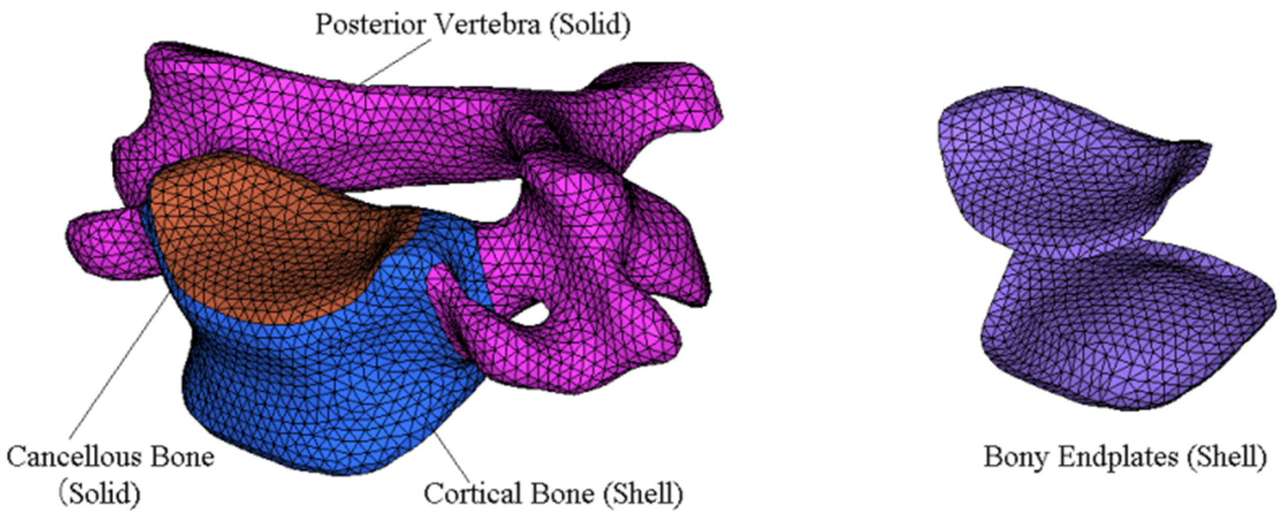
Figure 2.
(a) Finite element model of segments C2-C7; (b) finite element model of segments C5-C6; (c) intervertebral disc model.
Figure 2.
(a) Finite element model of segments C2-C7; (b) finite element model of segments C5-C6; (c) intervertebral disc model.
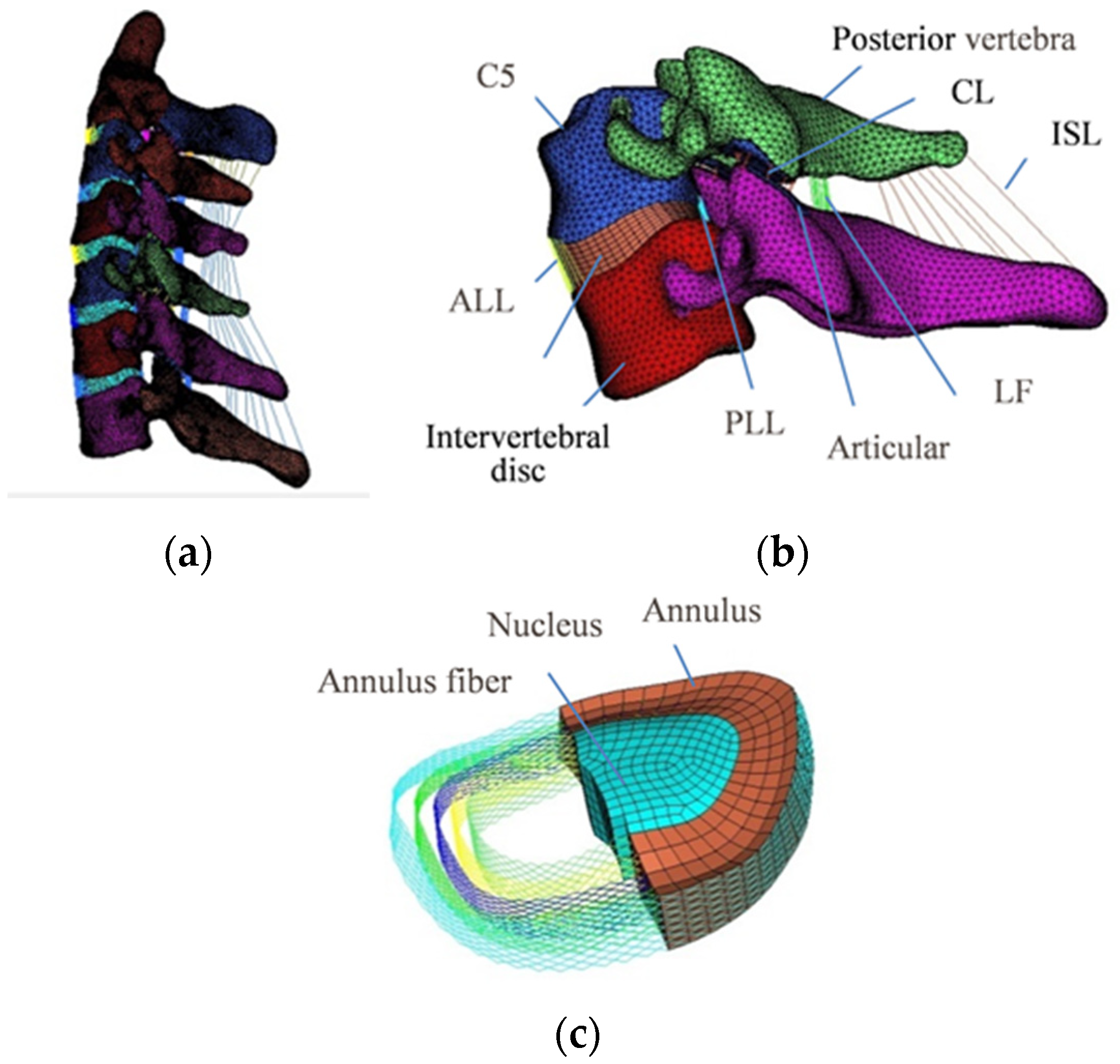
Figure 3.
Comparison of the results of the FE model and experimental studies in different segments under flexion (+) and extension (−) (data from [3,4,38]).


Figure 6.
Intervertebral disc stress on segments C4-C5 under axial compression (data from [39]).
Figure 6.
Intervertebral disc stress on segments C4-C5 under axial compression (data from [39]).

Figure 7.
Intervertebral disc stress on segments C3-C4 and C5-C6 under flexion/extension moment of 0.5 Nm and pre-compression load of 10 N (data from [40]).
Figure 7.
Intervertebral disc stress on segments C3-C4 and C5-C6 under flexion/extension moment of 0.5 Nm and pre-compression load of 10 N (data from [40]).


Table 1.
Element types and mechanical properties of the FE model.
| Component | Element Type | Young’s Modulus (MPa) | Poisson’s Ratio | Reference |
|---|---|---|---|---|
| Cortical bone | S3 | 12,000 | 0.29 | [18] |
| Cancellous bone | C3D4 | 100 | 0.29 | [32] |
| Posterior vertebra | C3D4 | 3500 | 0.29 | [18] |
| Articular cartilage | C3D6 | 10.4 | 0.4 | [33] |
| Endplate | S3 | 500 | 0.4 | [18] |
| Nucleus pulposus | C3D8H | Hyperelastic (C10 = 0.348, D1 = 0.3) | [34] | |
| Annulus ground substance | C3D8R | Hyperelastic (C10 = 0.12, C01 = 0.09) | [35] | |
| Annulus fiber | T3D2 | 358–550 | 0.3 | [36] |
| ALL | CONN3D2 | Nonlinear (Incompressible) | [19,37] | |
| PLL | CONN3D2 | - | - | |
| FL | CONN3D2 | - | - | |
| ISL | CONN3D2 | - | - | |
| CL | CONN3D2 | - | - |
Publisher’s Note: MDPI stays neutral with regard to jurisdictional claims in published maps and institutional affiliations. |
© 2022 by the authors. Licensee MDPI, Basel, Switzerland. This article is an open access article distributed under the terms and conditions of the Creative Commons Attribution (CC BY) license (https://creativecommons.org/licenses/by/4.0/).
Share and Cite
MDPI and ACS Style
Cheng, X.; Wang, T.; Pan, C. Finite Element Analysis and Validation of Segments C2-C7 of the Cervical Spine. Metals 2022, 12, 2056. https://doi.org/10.3390/met12122056
AMA Style
Cheng X, Wang T, Pan C. Finite Element Analysis and Validation of Segments C2-C7 of the Cervical Spine. Metals. 2022; 12(12):2056. https://doi.org/10.3390/met12122056
Chicago/Turabian StyleCheng, Xuejin, Tao Wang, and Changjiang Pan. 2022. "Finite Element Analysis and Validation of Segments C2-C7 of the Cervical Spine" Metals 12, no. 12: 2056. https://doi.org/10.3390/met12122056
Note that from the first issue of 2016, this journal uses article numbers instead of page numbers. See further details here.