
Research on the Fracture Behavior and Microstructure of T91 Steel at Ultrahigh Creep Temperatures
1
Institute of Reactor Engineering and Technology, China Institute of Atomic Energy, Beijing 102413, China
2
Faculty of Material Metallurgy and Chemistry, Jiangxi University of Science and Technology, Ganzhou 341000, China
*
Authors to whom correspondence should be addressed.
Metals 2022, 12(12), 2054; https://doi.org/10.3390/met12122054
Submission received: 5 November 2022
/
Revised: 25 November 2022
/
Accepted: 26 November 2022
/
Published: 29 November 2022
Abstract
:The creep behavior of T91 steel at ultrahigh creep temperatures (650–750 °C) at 100 MPa was investigated using small-size specimens, and the related microstructures were characterized. The results showed that the creep failure susceptibility of T91 steel increases significantly as the creep temperature increases from 650 °C to 675 °C. The creep life rapidly decreased from 7880 h to 224 h, and the fracture surface shrinkage increased from 61.9% to 86.5%. Thermodynamic calculations and microstructure observations showed that the increase in creep temperature has a significant effect on the morphology of M23C6-type carbides, which were distributed around grain boundaries, significantly pinning and hindering the movement of dislocations and the grain boundaries. As the creep temperature increases, the subcrystalline and M23C6-type carbides significantly coarsen, which is the main reason for the rapidly shortening creep life of T91 steel. This research provides guidance for the material design and microstructure regulation of T91 steel in service at ultrahigh environmental temperatures.
1. Introduction
T91 steel is a modified 9Cr–1Mo martensitic high-strength heat-resistant steel, which is characterized by high oxidation resistance, durable plasticity, and high and stable hot-strength properties. Thus, T91 steel is widely used in supercritical generating unit pipes, superheaters, reheaters, and other working parts in high-temperature steam environments [1]. In addition, T91 steel is usually selected as a cladding or in-stack structural material for fourth-generation reactors, such as sodium fast reactors (SFRs), supercritical water reactors (SCWRs), vessels of ultrahigh-temperature reactors (VHTRs), and accelerator-driven subcritical fast reactors (ADSs) [2,3,4,5].
At present, T91 steel is widely used in the electricity field, and its working temperature usually does not exceed 600 °C [6,7,8], but heat accumulation occurs when it is in service, due to the shapes and structures of the machine parts, which leads to T91 steel being hotter than its working temperature and more susceptible to failure [6,9,10,11]. The main reason for failure is that the carbides are prone to coarsening due to ultrahigh temperature or long-time creep. Taneike and Maruyama [12] suggested that the coarsening behavior of M23C6 and MX carbides can have a significant effect on creep lifetime, which is mainly attributed to the pegging effect of the particles on grain boundaries. It is important to note that various carbide particles have different effects on grain boundaries, depending on their own properties. Generally, M23C6-type carbides are more effective in preventing subgrain migration than MX-type carbides in heat-resistant steels, because the M23C6 precipitated phase and subgrain sizes are similar under static and creep loading conditions [13]. Owing to the small size, MX precipitates are rarely noticed at the subgrain boundaries, which inhibits the grain boundary movement [14]. In addition, long-time creep is prone to causing precipitation of Laves and Z phases, which is also an important factor limiting creep life [15]. Therefore, it is important to prevent the coarsening of carbides to enhance the creep strength and life of heat-resistant steels [16].
T91 steel has been gradually applied in the nuclear power field, but the volume of the sample is directly proportional to the radioactive intensity of the irradiated sample, and the large size of the sample is more radioactive, which is not favorable to experimental operation, thus increasing testing difficulty. In addition, the gradient of irradiation parameters (including temperature and dose) is large in the reactor, and standard samples suffer from inhomogeneity of irradiation parameters. Therefore, non-standard, small-dimensional samples are currently preferred for testing and analyzing the mechanical property evaluation of material irradiation [17,18], especially in fusion materials research. However, small-dimensional samples have obvious size effects, high testing accuracy, and material homogeneity [19,20,21,22], and there is still no standard evaluating system [23], which seriously restricts the research on the mechanical properties of some heat-resistant steels in the field of irradiation.
Therefore, in this paper, the fracture behavior and microstructural changes of T91 steel at ultrahigh creep temperatures are investigated using small samples, which have important significance and a reference value for the optimization of creep models and the service of T91 steel in vital parts of nuclear power units. Meanwhile, this research also further expands the studies on the creep properties of small-size specimens and provides a reference for the study of mechanical properties for small-size specimens after irradiation.
2. Materials and Methods
A domestic T91 steel plate material was used for the test, and Table 1 presents the alloy composition. Creep samples were selected according to the small specimen-japan (SS-J) [24], and small samples (Figure 1a) with a pitch section 5 mm in length and cross-sectional dimensions of 1.5 × 0.75 mm2 were used. Distance segments were marked with a laser-marking machine prior to the test in order to determine the elongation after fracture. The creep testing of small samples was carried out using an MTS GWT1104 mechanical creep machine (MTS Systems (China) Co., Ltd., Shenzhen, China) (Figure 1b) with customized clamps in accordance with the Chinese standard GB/T 2039-2012 Metallic Materials—Uniaxial creep testing method in tension at 650, 675, 700, and 750 °C with a test stress of 100 MPa. The machine applies a load of 20 times weight to the sample through a lever, which can keep the creep stress constant for a long time during the test. The test temperature is controlled by an atmosphere furnace equipped with the creep machine. The difference between the actual test temperature and the set temperature is within 4 °C, which meets the standard requirements.
The creep fracture time, steady-state creep rate, and apparent creep activation energy were obtained by analyzing the creep test curve at the end of the creep experiment. The section lengths were measured before and after creep, and the elongation was calculated to obtain the elongation after fracture. As the small cross-sectional area of the sample fracture made it difficult to obtain the fracture section shrinkage by the usual methods, the fracture area was measured from a scanning electron microscopy (SEM) image. As shown in Figure 2, the fracture on the SEM image was roughly outlined using ImageJ software, the section area was automatically measured using ImageJ software (version 1.51j8, National Institutes of Health, MD, USA) and the section shrinkage was then calculated according to the corresponding equation.
To obtain an accurate understanding of the various precipitates in the heating of T91 steel, thermodynamic calculation of the heating was carried out using Jmat-Pro software. Fracture observation was carried out with a ZEISS ULTRA 55 scanning electron microscope (Carl Zeiss Microscopy Ltd., Cambridge, UK). A small part of the creep sample was cut 3 mm away from the fracture using wire electrical-discharge machining. To deeply analyze the martensitic lath morphology, dislocation density, and precipitates in the microstructure of T91 steel, the experimental samples were analyzed using FEI Talos F200X transmission electron microscopy (TEM, Thermo Fisher Scientific, Shanghai, China). Before TEM observation, the samples were prepared using a focused ion beam (FIB).
3. Results and Discussion
3.1. Creep Behavior
The creep curves are shown in Figure 3a,b. The plot of creep strain versus time indicates the creep behavior in terms of three stages. The decelerated creep stage is not obvious, but mainly, the steady-state creep stage is. This is mainly attributed to the smaller deformation resistance and rapid deformation rate of T91 steel at the early stage of creep, which rapidly accumulates dislocations, resulting in work hardening. The increase in work hardening caused the dynamic recovery rate to increase, and finally, the work hardening and recovery softening reached dynamic equilibrium in a brief time, which caused the creep to go into the steady-state creep stage. Therefore, it can be seen from Figure 3 that the creep rate going from deceleration to equilibrium is insignificant. Figure 3b shows that when the creep temperature was 650 °C, the strain was low (no more than 20%) and had the lowest steady-state creep rate and the highest creep life (more than 7800 h). This shows that deformation-induced work hardening and dynamic recovery maintain a dynamic balance for a long time. As the creep temperature increased, the accelerated creep stage became more significant and the creep life shortened, which indicates that the creep temperature has a significant effect on T91 steel. Therefore, it is obvious that when the creep temperature is 675 °C, the creep rate increases rapidly and the creep life decreases significantly as creep carries on to 224 h. As the creep temperature continues to increase, the steady-state creep stage gradually shortens, which is almost not obvious at 750 °C. In addition, it is clear from Figure 3a,c that the creep rate increased rapidly and fracture occurred at 750 °C within a brief time, and the main reason can be attributed to smaller dislocation pinning of precipitates [13,25] and lower intergranular slip resistance than lower creep temperatures.
With the increase in creep temperature, more significant creep characteristics were found, as shown in Figure 3c–e. Figure 3e shows the variations in the elongation and area shrinkage of T91 steel after fracture with temperature. As the temperature increased, the post-fracture elongation increased until it reached the maximum value at 700 °C at constant creep stress (100 MPa). The area shrinkage increased gradually with increasing temperature at constant creep stress (100 MPa). It should be noted that the change in the area shrinkage was obvious at 650–675 °C, but the change at 675–750 °C was slight.
The creep resistance of a material can usually be reflected by the minimum creep rate, which can usually be replaced by the steady-state creep rate εm; thus, the steady-state creep rate is a critical creep parameter. The relationship between εm and the test temperature T follows the Arrhenius law and can be expressed as [26,27]:
where R is the gas constant, whose value is 8.314 J/(mol∙K); T is the test temperature (K); Qc is the apparent creep activation energy (kJ/mol); and A is a constant related to the material properties. The apparent creep activation energy of T91 steel is 656.4 kJ/mol according to Equation (1), which is much higher than the self-diffusion activation energy of atoms in α-Fe (250 kJ/mol) [26], which indicates that the steady-state creep rate is not controlled by dislocation climbing.
According to the mechanism of continuous creep fracture, the damage tolerance factor λ can be obtained from the creep fracture time tr, the steady-state creep rate εm, and elongation after fracture, εr [12,28]:
where λ represents the deformation resistance of the material before creep fracture, which is related to the mechanism of accelerated creep and the final fracture. λ originates from the M-G (Monkman–Grant) relationship [29]:
where C0 and α are constants. The M-G relationship is applicable to a wide range of materials and temperatures. Since the deformation and fracture in the creep are interrelated, the M-G relationship is modified as [30]:
where εr is the fracture strain and CMMG is the constant related to temperature and stress [29]. For the convenience of calculation, take α = 1, and λ is the reciprocal of CMMG, i.e.,
Wilshire and Burt [12] suggested that there are many factors contributing to the creep rate increase in the third creep stage, including the formation of grain boundary cavities and coarsening of particles. They concluded that when 1 < λ < 2.5, the final fracture in the third creep stage is caused by cavities; when λ > 2.5, the final fracture in the third creep stage is caused by dislocation movement; and when λ > 5, the main cause is the coarsening of the precipitated phase.
According to Equation (2), the results of λ are shown in Table 2, from which it can be seen that λ > 5 under all test conditions, which further indicates that creep fracture is not caused by dislocation movement but mainly by precipitation coarsening.
3.2. Fractography Examination
The fracture microstructure of the creep sample at 650~750 °C is shown in Figure 4. It can be visually seen from the figure that the specimens exhibited significant necking and plastic deformation over 650 °C. The fracture shrinkage gradually increased with increasing temperature, especially in Figure 4a,b, where the creep temperature increased from 650 °C to 675 °C, the fracture shrinkage was drastic, and the shrinkage fraction increased from 61.87% to 86.48%. However, as the temperature continued to increase from 675 °C to 750 °C, as shown in Figure 4b–d, there was not much change in fracture shrinkage. This indicates that the fracture shrinkage sensitivity of T91 steel is large and the creep life rapidly shortens from 650 °C to 675 °C. As the creep temperature increased from 650 °C to 750 °C, the fracture morphology of all samples was mainly composed of dimples and cavities, and the fracture mechanism was microporous aggregation ductile fracture. At 650 °C, the fracture was composed of large and deep dimples and many small and shallow secondary dimples. The fracture morphologies from 675 °C to 750 °C were similar, and there were many shear dimples. The dimple size did not change significantly with temperature, and there were no dense dimples similar to those in the fracture at 650 °C. The change in fracture morphology was consistent with the changes in elongation and area shrinkage after fracture.
Figure 5 shows the typical fracture morphology for the creep temperatures of 650 °C and 750 °C. From the figure, it is once again clear that the creep temperature has a significant effect on the creep fracture morphology of T91 steel. When the temperature was low, there were more dimples and cavities; in addition, the existence of precipitated phases was seen in some dimples with a small size. However, when the creep temperature was 750 °C, the fracture was mainly creep cavities with almost no dimples, but coarse precipitated phases were found around some larger-size cavities. The energy spectrum analysis (EDS) of the precipitated phases showed that they are mainly carbonitrides with the elements V and Nb. Therefore, it can be assumed that these precipitated phases are MN-type carbonitrides commonly found in T91 steel, which are reported in many studies [6,9,31]. This phenomenon indicates that the increase in the creep temperature will cause a change in the precipitated phase in T91 steel, which is the main reason for the difference in creep fracture morphology and creep life. Therefore, it can be assumed that the precipitated phase plays an important role in the creep of T91 steel, and the effect of creep temperature on the precipitated phase will be investigated subsequently.
3.3. Precipitates
According to the results of creep behavior and fractography examination, temperature has a significant effect on the fracture behavior and microstructure of T91 steel. It can be inferred from the calculation of the creep damage tolerance factor that many dispersed precipitates in T91 steel are key factors that cause the change in creep behavior and fractography. Therefore, to investigate the role of precipitates in creep, thermodynamic calculations were performed on the precipitates of T91 steel. The changes in various precipitates during solidification are shown in Figure 6. When the temperature increased from 600 °C to 800 °C, the types and contents of precipitated phases were significantly different. For example, as the solidification temperature decreased from 800 °C, M23C6-type, Z phase, and MN-type carbides (MN in T91 steel mainly refers to VC, VN, NbC, and NbN) changed more significantly. In addition, it is worth noting that the formation of the Z phase and the disappearance of MN occurred almost simultaneously, as shown in Figure 6b. According to relevant reports [31], after long-time aging, the precipitation and growth of the Z phase come at the cost of MX-type carbonitride consumption in T91 steel, so there is a mutual transformation relationship between MN-type nitride and the Z phase. It should be noted that although Figure 6 reflects the change in the precipitated phase during solidification for T91 steel, it can still provide a reference for us to investigate the change in the precipitated phase for T91 steel long-time creep. It can be seen from Figure 6 that the change in the precipitated phase is sensitive to temperature, especially from 600 °C to 800 °C. The precipitates have a significant effect on creep behavior, which can be attributed to their producing a strong pinning effect and prolonging the creep life of materials [9,32,33].
To further verify the results of thermodynamic calculations and analyze the martensitic lath morphology, dislocation density, and precipitated phase type, morphology, and distribution of T91 steel, TEM was performed on the initial sample and creep samples at 650 °C and 700 °C. The results are shown in Figure 7. The figure shows the initial microstructure was mainly martensite lath, and there were many dislocations but no obvious precipitated phase. After long-time creep at 650 °C and 700 °C, the lath martensite disappeared, and many precipitated phases distributed along the grain boundaries were observed. The size of the precipitates in Figure 7c is larger than that in Figure 7b. This shows that a higher creep temperature coarsens the precipitated phase obviously, which weakens the pinning effect on the grain boundary. The precipitated phases in Figure 7c were mainly distributed at the grain boundaries with sizes of 200–300 nm [34], and some dislocations were present around the precipitated phases. The distribution of precipitated phases at the grain boundaries hinders the movement and extinction of dislocations and strongly inhibits the migration of the grain boundaries [6,14].
Selected electron diffraction (SAED) and energy spectrum analysis (EDS) were performed on the precipitated phases around the grain boundaries, and the results are shown in Figure 8. According to the figure, the precipitated phases that were distributed diffusely along the martensitic lath boundary and the primary austenite grain boundary were mainly M23C6-type carbides and Laves phase [2], which is consistent with the calculated results in Figure 6, where M corresponds mainly to Cr, Fe, and Mo. It is noteworthy that the M23C6-type carbide and Laves phases have an Fe2Mo[612]//M23C6[110] orientation relationship. The size of the M23C6 precipitated phase is relatively larger at the grain boundary distribution in Figure 8d,e because the higher creep temperature causes more serious coarsening of the M23C6 precipitated phase; thus, most of the precipitated phases exceed 200 nm. The TEM results are consistent with the results of previous thermodynamic calculations and the relevant literature. Notably, during creep, the precipitated phases can strongly hinder grain boundary slippage and dislocation movements during high-temperature creep, which significantly improves the creep resistance [25,31]. However, as the creep temperature increases, the martensitic matrix undergoes subcrystalline coarsening due to high-temperature creep. The morphology changes to coarse granular precipitation phases that are distributed in the massive ferrite matrix, and the M23C6-type precipitated phase grows rapidly due to Ostwald ripening, which results in creep voids in the microstructure, eventually causing the material to fail and fracture.
4. Conclusions
- (1)
- As the creep test temperature of T91 steel increases from 650 °C to 750 °C, the creep rate increases, the steady-state creep stage shortens, and the creep life decreases. The elongation increases initially, reaching a maximum at 700 °C, and then decreases slightly, whereas the section shrinkage increases consistently.
- (2)
- T91 steel exhibits significant plastic deformation at ultrahigh creep temperatures. As the creep temperature increases from 650 °C to 750 °C, the sample section shrinkage increases, and the fracture time decreases. The creep fracture time decreases rapidly from 650 °C to 675 °C, and T91 steel exhibits a strong susceptibility to failure.
- (3)
- The T91 steel precipitated phases along the grain boundaries are mainly M23C6-type carbides at ultrahigh creep temperatures, which have a strong pegging effect on dislocations and grain boundaries and can significantly improve the creep resistance. However, as the creep temperature increases, the creep resistance gradually decreases, which is primarily caused by the martensitic subcrystalline coarsening and transformation of the carbide morphology.
Author Contributions
Conceptualization, Q.Z., W.Z. and Z.W.; methodology, Q.Z., B.B. and C.H.; software, W.Y. and B.B.; validation, Q.Z. and C.H.; formal analysis, Q.Z.; investigation, Q.Z. and C.H.; resources, W.Z. and Z.W.; data curation, Q.Z. and B.B.; writing—original draft preparation, Q.Z. and C.H.; writing—review and editing, Q.Z. and Z.W.; visualization, B.B. and W.Y.; supervision, W.Z. and Z.W.; project administration, W.Z. and Z.W.; funding acquisition, Q.Z., C.H. and Z.W. All authors have read and agreed to the published version of the manuscript.
Funding
This research was funded by the CNNC Advance Development Project (grant number FA18000120), the Key Research and Development Program of Jiangxi Province (grant number 20192ACB50010), and the Graduate Innovation Special Fund Project of Jiangxi Province in 2021 (YC2021-S564).
Institutional Review Board Statement
Not applicable.
Data Availability Statement
Not applicable.
Conflicts of Interest
The authors declare no conflict of interest. The funders had no role in the design of the study; in the collection, analyses, or interpretation of data; in the writing of the manuscript; or in the decision to publish the results.
References
- Shrestha, T.; Basirat, M.; Charit, I.; Potirniche, G.P.; Rink, K.K. Creep rupture behavior of Grade 91 steel. Mater. Sci. Eng. A 2013, 565, 382–391. [Google Scholar] [CrossRef]
- Shrestha, T.; Basirat, M.; Alsagabi, S.; Sittiho, A.; Charit, I.; Potirniche, G.P. Creep rupture behavior of welded Grade 91 steel. Mater. Sci. Eng. A 2016, 669, 75–86. [Google Scholar] [CrossRef] [Green Version]
- Guguloth, K.; Roy, N. Study on the creep deformation behavior and characterization of 9Cr-1Mo-V-Nb steel at elevated temperatures. Mater. Charact. 2018, 146, 279–298. [Google Scholar] [CrossRef]
- Fan, P.; Liu, X.; Peng, J.; Zhu, L.; Zhang, K. Quantitative assessment of creep damage in 9Cr-1Mo steel using nonlinear Lamb wave. Mater. Charact. 2021, 171, 110771. [Google Scholar] [CrossRef]
- Sathyanarayanan, S.; Moitra, A.; Samuel, K.G.; Sasikalaa, G.; Ray, S.K.; Singh, V. Evaluation of dynamic fracture toughness based reference temperature (T-0(dy)) of modified 9Cr-1Mo steel in phosphorus embrittled and cold-worked condition. Mat. Sci. Eng. Struct. 2008, 488, 519–528. [Google Scholar] [CrossRef]
- Sawada, K.; Kushima, H.; Tabuchi, M.; Kimura, K. Microstructural degradation of Gr.91 steel during creep under low stress. Mater. Sci. Eng. A 2011, 528, 5511–5518. [Google Scholar] [CrossRef]
- Abe, F. Analysis of creep rates of tempered martensitic 9%Cr steel based on microstructure evolution. Mater. Sci. Eng. A 2009, 510–511, 64–69. [Google Scholar] [CrossRef]
- Choudhary, B.; Samuel, E.I. Creep behaviour of modified 9Cr–1Mo ferritic steel. J. Nucl. Mater. 2011, 412, 82–89. [Google Scholar] [CrossRef]
- Hald, J. Microstructure and long-term creep properties of 9–12% Cr steels. Int. J. Press. Vessel. Pip. 2008, 85, 30–37. [Google Scholar] [CrossRef]
- Abram, T.; Ion, S. Generation-IV nuclear power: A review of the state of the science. Energy Policy 2008, 36, 4323–4330. [Google Scholar] [CrossRef]
- Guguloth, K.; Roy, N. Creep deformation behavior of 9Cr1MoVNb (ASME Grade 91) steel. Mater. Sci. Eng. A 2017, 680, 388–404. [Google Scholar] [CrossRef]
- Wilshire, B.; Burt, H. Damage evolution during creep of steels. Int. J. Press. Vessel. Pip. 2008, 85, 47–54. [Google Scholar] [CrossRef]
- Pandey, C.; Mahapatra, M.; Kumar, P.; Vidyrathy, R.; Srivastava, A. Microstructure-based assessment of creep rupture behaviour of cast-forged P91 steel. Mater. Sci. Eng. A 2017, 695, 291–301. [Google Scholar] [CrossRef]
- Panait, C.G.; Zielinska-Lipiec, A.; Koziel, T.; Czyrska-Filemonowicz, A.; Gourgues-Lorenzon, A.F.; Bendick, W. Evolution of dislocation density, size of subgrains and MX-type precipitates in a P91 steel during creep and during thermal ageing at 600 degrees C for more than 100,000 h. Mat. Sci. Eng. Struct. 2010, 527, 4062–4069. [Google Scholar] [CrossRef] [Green Version]
- Pandey, C.; Mahapatra, M.M.; Kumar, P.; Saini, N. Comparative study of autogenous tungsten inert gas welding and tungsten arc welding with filler wire for dissimilar P91 and P92 steel weld joint. Mater. Sci. Eng. A 2018, 712, 720–737. [Google Scholar] [CrossRef]
- Pandey, C.; Giri, A.; Mahapatra, M. Evolution of phases in P91 steel in various heat treatment conditions and their effect on microstructure stability and mechanical properties. Mater. Sci. Eng. A 2016, 664, 58–74. [Google Scholar] [CrossRef]
- Tong, Z.; Dai, Y. The microstructure and tensile properties of ferritic/martensitic steels T91, Eurofer-97 and F82H irradiated up to 20dpa in STIP-III. J. Nucl. Mater. 2010, 398, 43–48. [Google Scholar] [CrossRef]
- Wakai, E.; Kikuchi, T.; Kim, B.; Kimura, A.; Nogami, S.; Hasegawa, A.; Nishimura, A.; Soldaini, M.; Yamamoto, M.; Knaster, J. Overview on recent progress toward small specimen test technique. Fusion Eng. Des. 2015, 98–99, 2089–2093. [Google Scholar] [CrossRef]
- Kumar, K.; Pooleery, A.; Madhusoodanan, K.; Singh, R.; Chatterjee, A.; Dutta, B.; Sinha, R. Optimisation of thickness of miniature tensile specimens for evaluation of mechanical properties. Mater. Sci. Eng. A 2016, 675, 32–43. [Google Scholar] [CrossRef]
- Sergueeva, A.; Zhou, J.; Meacham, B.; Branagan, D. Gage length and sample size effect on measured properties during tensile testing. Mater. Sci. Eng. A 2009, 526, 79–83. [Google Scholar] [CrossRef]
- Odette, G.; Yamamoto, T.; Kishimoto, H.; Sokolov, M.; Spätig, P.; Yang, W.; Rensman, J.-W.; Lucas, G. A master curve analysis of F82H using statistical and constraint loss size adjustments of small specimen data. J. Nucl. Mater. 2004, 329–333, 1243–1247. [Google Scholar] [CrossRef]
- Bonadé, R.; Spätig, P.; Baluc, N. Fracture toughness properties in the transition region of the Eurofer97 tempered martensitic steel. J. Nucl. Mater. 2007, 367–370, 581–586. [Google Scholar] [CrossRef]
- Wakai, E.; Nogami, S.; Kasada, R.; Kimura, A.; Kurishita, H.; Saito, M.; Ito, Y.; Takada, F.; Nakamura, K.; Molla, J.; et al. Small specimen test technology and methodology of IFMIF/EVEDA and the further subjects. J. Nucl. Mater. 2011, 417, 1325–1330. [Google Scholar] [CrossRef]
- Kohno, Y.; Kohyama, A.; Hamilton, M.L.; Hirose, T.; Katoh, Y.; A Garner, F. Specimen size effects on the tensile properties of JPCA and JFMS. J. Nucl. Mater. 2000, 283–287, 1014–1017. [Google Scholar] [CrossRef]
- Pandey, C.; Mahapatra, M.M. Effect of Long-term Ageing on the Microstructure and Mechanical Properties of Creep Strength Enhanced Ferritic P91 Steel. Trans. Indian Inst. Met. 2016, 69, 1657–1673. [Google Scholar] [CrossRef]
- Shrestha, T.; Basirat, M.; Charit, I.; Potirniche, G.P.; Rink, K.K.; Sahaym, U. Creep deformation mechanisms in modified 9Cr–1Mo steel. J. Nucl. Mater. 2012, 423, 110–119. [Google Scholar] [CrossRef]
- Haney, E.M.; Dalle, F.; Sauzay, M.; Vincent, L.; Tournié, I.; Allais, L.; Fournier, B. Macroscopic results of long-term creep on a modified 9Cr–1Mo steel (T91). Mater. Sci. Eng. A 2009, 510–511, 99–103. [Google Scholar] [CrossRef]
- Rabotnov, Y.N.; Leckie, F.A.; Prager, W. Creep Problems in Structural Members. J. Appl. Mech. 1970, 37, 249. [Google Scholar] [CrossRef]
- Phaniraj, C.; Choudhary, B.; Rao, K.B.S.; Raj, B. Relationship between time to reach Monkman–Grant ductility and rupture life. Scr. Mater. 2003, 48, 1313–1318. [Google Scholar] [CrossRef]
- Ali, H.O.; Tamin, M.N. Modified Monkman–Grant relationship for austenitic stainless steel foils. J. Nucl. Mater. 2013, 433, 74–79. [Google Scholar] [CrossRef]
- Sawada, K.; Kushima, H.; Kimura, K. Z-phase Formation during Creep and Aging in 9–12% Cr Heat Resistant Steels. ISIJ Int. 2006, 46, 769–775. [Google Scholar] [CrossRef] [Green Version]
- Chen, R.; Armaki, H.G.; Maruyama, K.; Igarashi, M. Long-term microstructural degradation and creep strength in Gr.91 steel. Mater. Sci. Eng. A 2011, 528, 4390–4394. [Google Scholar] [CrossRef]
- Agamennone, R.; Blum, W.; Gupta, C.; Chakravartty, J. Evolution of microstructure and deformation resistance in creep of tempered martensitic 9–12%Cr–2%W–5%Co steels. Acta Mater. 2006, 54, 3003–3014. [Google Scholar] [CrossRef]
- Kimura, K.; Kushima, H.; Sawada, K. Long-term creep deformation property of modified 9Cr–1Mo steel. Mater. Sci. Eng. A 2009, 510–511, 58–63. [Google Scholar] [CrossRef]
Figure 1.
(a) Small creep specimen (unit: mm) and (b) GWT1104 high-temperature creep-testing machine.
Figure 1.
(a) Small creep specimen (unit: mm) and (b) GWT1104 high-temperature creep-testing machine.
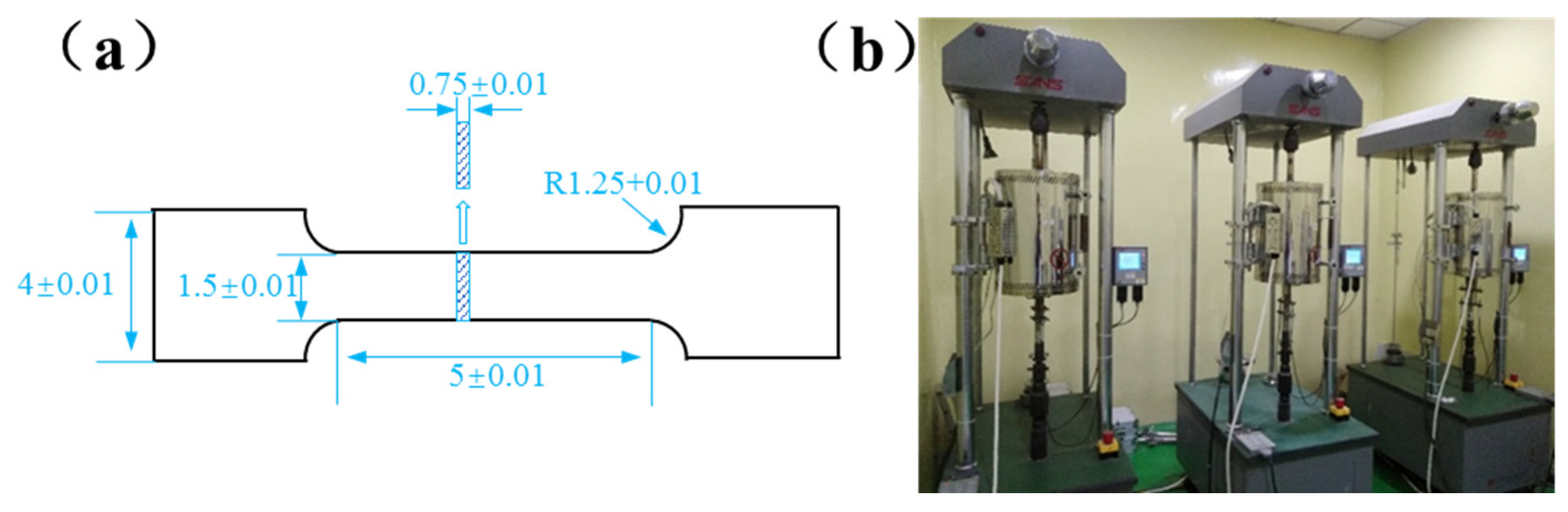
Figure 2.
Fracture area calculation using ImageJ software.

Figure 3.
(a,b) Creep curves, (c) creep lifetime of T91 steel at different temperatures, (d) fitting analysis of the apparent activation energy of T91 steel, and (e) creep fracture plasticity at different temperatures.
Figure 3.
(a,b) Creep curves, (c) creep lifetime of T91 steel at different temperatures, (d) fitting analysis of the apparent activation energy of T91 steel, and (e) creep fracture plasticity at different temperatures.
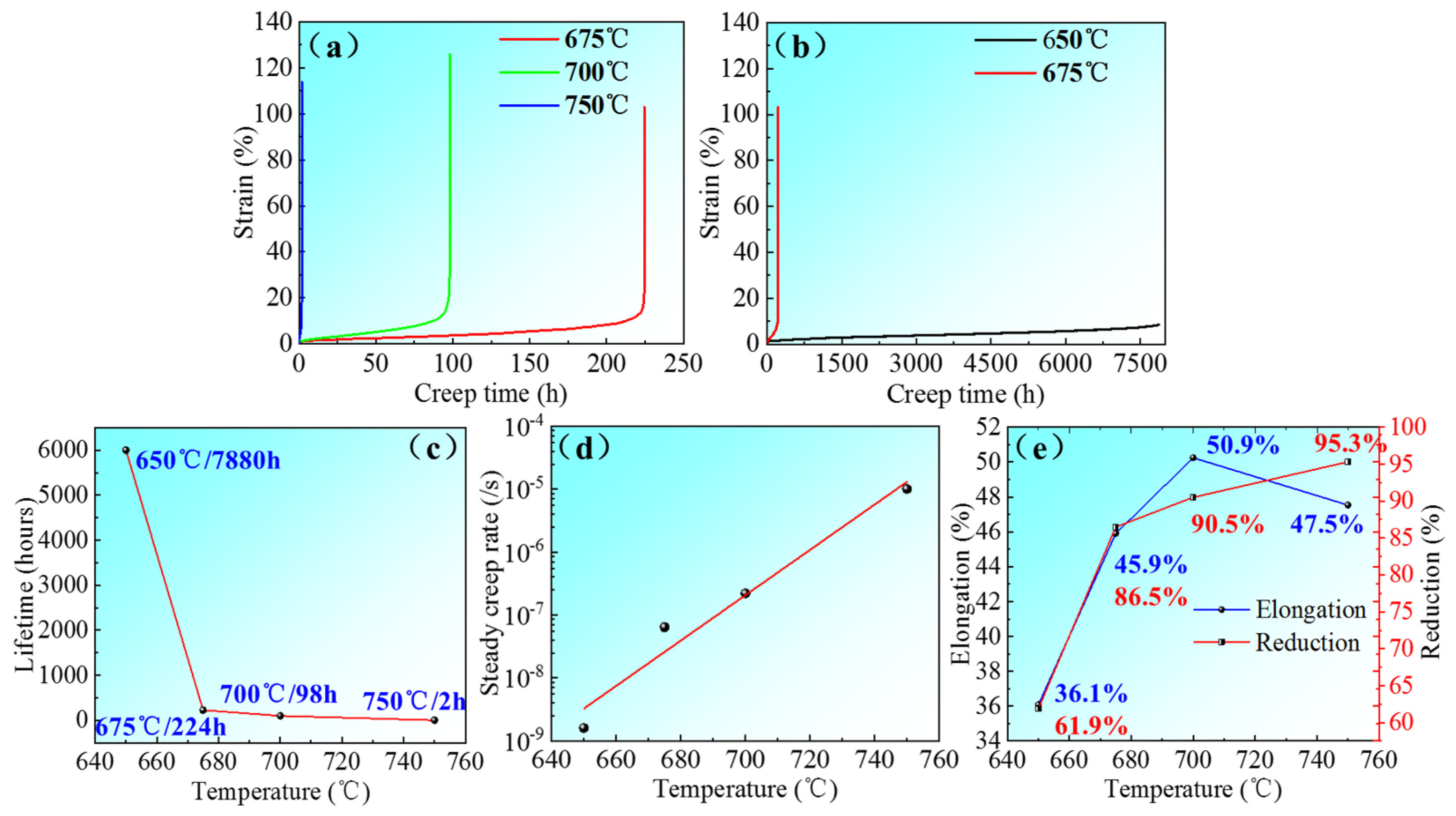
Figure 4.
Typical SEM fractographs of T91 steel creep at (a,a1) 650 °C, (b,b1) 675 °C, (c,c1) 700 °C, and (d,d1) 750 °C.
Figure 4.
Typical SEM fractographs of T91 steel creep at (a,a1) 650 °C, (b,b1) 675 °C, (c,c1) 700 °C, and (d,d1) 750 °C.

Figure 5.
Typical SEM fractographs of T91 steel creep at (a,b) 650 °C, (c) 750 °C, and (d) is the energy spectrum analysis (EDS) of the second phase in (c).
Figure 5.
Typical SEM fractographs of T91 steel creep at (a,b) 650 °C, (c) 750 °C, and (d) is the energy spectrum analysis (EDS) of the second phase in (c).
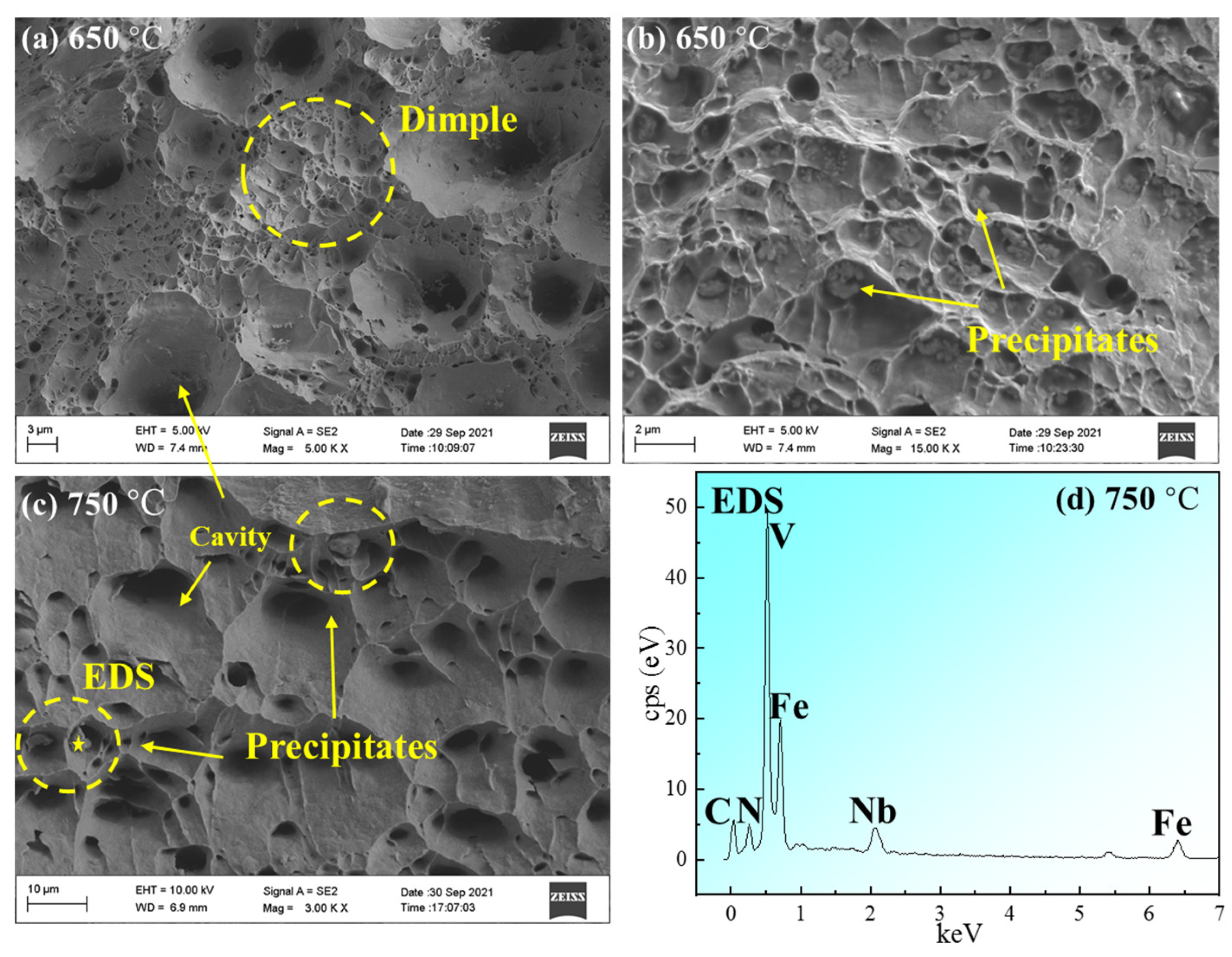
Figure 6.
(a) The results of the T91 steel phase change with temperature that were calculated using Jmat-Pro software (version 9.0, Sente Software Ltd., Guildford, UK) and (b) the area of interest.
Figure 6.
(a) The results of the T91 steel phase change with temperature that were calculated using Jmat-Pro software (version 9.0, Sente Software Ltd., Guildford, UK) and (b) the area of interest.
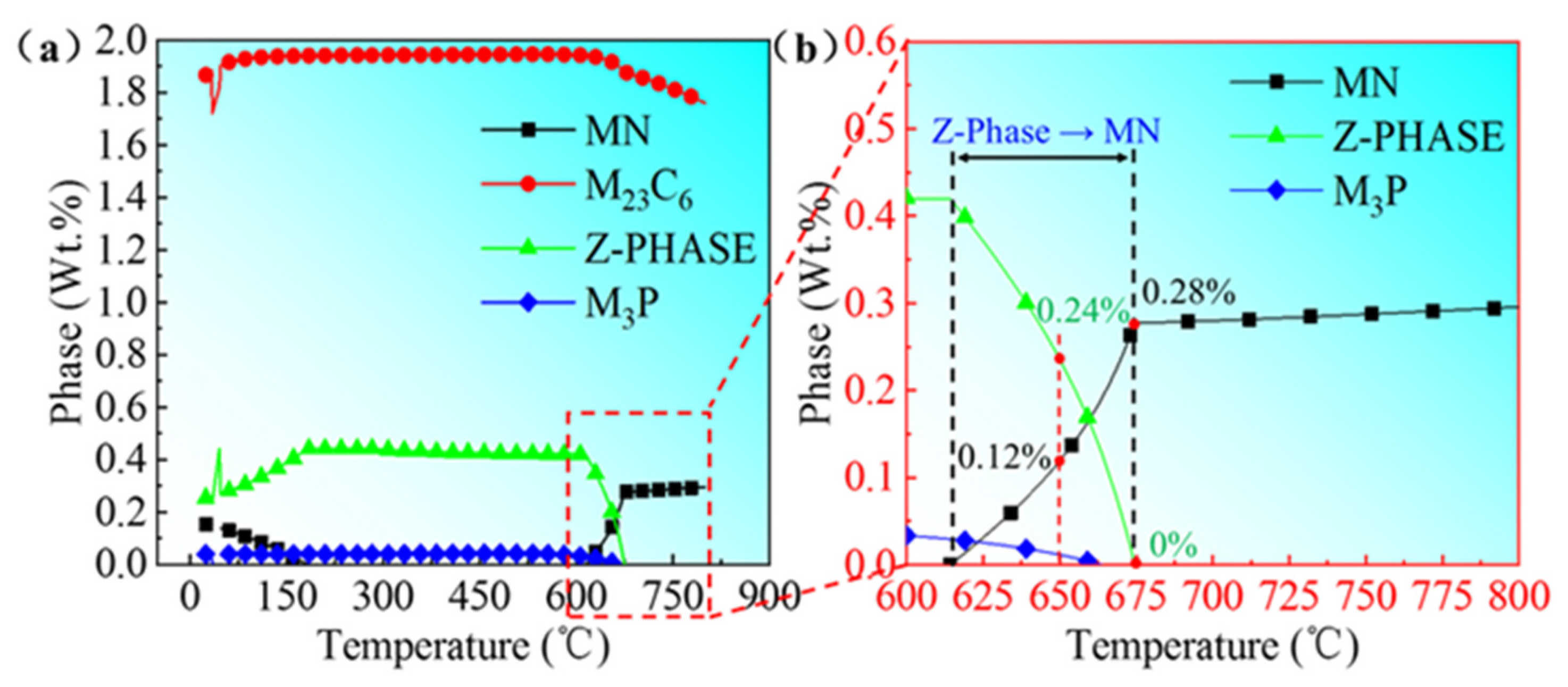
Figure 7.
TEM morphological images of T91 steel for (a) initial microstructure, (b) 650 °C, and (c) 700 °C.
Figure 7.
TEM morphological images of T91 steel for (a) initial microstructure, (b) 650 °C, and (c) 700 °C.

Figure 8.
EDS and SAED images for the precipitates of T91 steel creep at (a–c) 650 °C and (d–f) 700 °C.
Figure 8.
EDS and SAED images for the precipitates of T91 steel creep at (a–c) 650 °C and (d–f) 700 °C.


Table 1.
Chemical composition of T91 steel (wt.%).
| Cr | Mo | V | Nb | N | Mn | Si | C | Ni | Al | P | S | Cu | Na |
|---|---|---|---|---|---|---|---|---|---|---|---|---|---|
| 9.02 | 0.92 | 0.2 | 0.072 | 0.049 | 0.42 | 0.32 | 0.1 | 0.065 | 0.012 | 0.0066 | <0.002 | 0.024 | 0.018 |
Table 2.
Calculated values of the damage tolerance factor.
| Creep temperature (°C) | 650 | 675 | 700 | 750 |
| Calculated value | 7.95 | 8.86 | 6.44 | 7.33 |
Publisher’s Note: MDPI stays neutral with regard to jurisdictional claims in published maps and institutional affiliations. |
© 2022 by the authors. Licensee MDPI, Basel, Switzerland. This article is an open access article distributed under the terms and conditions of the Creative Commons Attribution (CC BY) license (https://creativecommons.org/licenses/by/4.0/).
Share and Cite
MDPI and ACS Style
Zheng, Q.; Zhong, W.; Bai, B.; Yang, W.; Wang, Z.; Huang, C. Research on the Fracture Behavior and Microstructure of T91 Steel at Ultrahigh Creep Temperatures. Metals 2022, 12, 2054. https://doi.org/10.3390/met12122054
AMA Style
Zheng Q, Zhong W, Bai B, Yang W, Wang Z, Huang C. Research on the Fracture Behavior and Microstructure of T91 Steel at Ultrahigh Creep Temperatures. Metals. 2022; 12(12):2054. https://doi.org/10.3390/met12122054
Chicago/Turabian StyleZheng, Quan, Weihua Zhong, Bing Bai, Wen Yang, Zhigang Wang, and Chengcong Huang. 2022. "Research on the Fracture Behavior and Microstructure of T91 Steel at Ultrahigh Creep Temperatures" Metals 12, no. 12: 2054. https://doi.org/10.3390/met12122054
Note that from the first issue of 2016, this journal uses article numbers instead of page numbers. See further details here.