
Application of Optimizing Slab Corner Shapes to Reduce Edge Seam Defect on Heavy Plates

1
National Engineering and Research Center of Continuous Casting Technology, Central Iron and Steel Research Institute, Beijing 100081, China
2
Zhongda National Engineering and Research Center of Continuous Casting Technology Co., Ltd., Beijing 100081, China
3
Material Digital R&D Center, China Iron and Steel Research Institute Group, Beijing 100081, China
*
Authors to whom correspondence should be addressed.
Metals 2022, 12(11), 1984; https://doi.org/10.3390/met12111984
Submission received: 10 October 2022
/
Revised: 14 November 2022
/
Accepted: 17 November 2022
/
Published: 19 November 2022
(This article belongs to the Special Issue Computational Methods in Metallic Materials Manufacturing Processes)
Abstract
:The edge seam defect is a common defect in hot rolling heavy plates. It can be improved by optimizing the corner shapes of slabs. Based on a numerical analysis of the effects of the slab corner shape on the temperature distribution after the slab’s exit from the heating furnace, three rolling methods are proposed for controlling the two-chamfered slab corner shape. The stress and deformation of the corner of the slab during the two-chamfered rolling process are investigated using a numerical simulation. The results show that a two-chamfered shape slab has the smallest temperature drop during the cooling process, and the slab corner can maintain higher temperature and uniformity, which is beneficial for controlling the deformation during the rolling process. Among the three kinds of two-chamfered rolling methods, frontal rolling using a two-roller has the smallest rolling force and rolling resistance to the casting machine, followed by horizontal rolling and then vertical rolling, which has the largest. The favorable slab corner in a two-chamfered shape can be obtained by frontal rolling using a two-roller. Industrial trials confirm that an edge seam defect rate of less than 5% in heavy plates can be achieved under the condition of a large broadside ratio.
1. Introduction
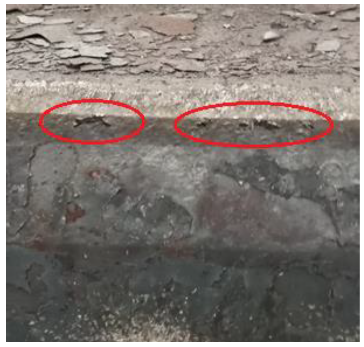
Edge seam defects or edge black lines, edge warping, etc., are linear defects that appear on the edge of hot-rolled sheets and plate surfaces. The appearance is similar to the defects caused by longitudinal cracks on the surface of the slab [1,2,3]. In the production of strip steels, low-carbon and ultra-low thin-gauge carbon steel and micro-alloyed high-strength thick-gauge steel are prone to generate edge seam defects which are 10~20 mm away from the edge and its depth of 200~400 μm [2,3,4]. In the production of heavy plates, due to the application of the broadside rolling process and the small compression ratio, edge seam defects can occur within a range of about 10 to 60 mm from the edge of the plate, and the crack depth can reach more than 2.0 mm. The position of the edge seam defect moves further from the plate edge with the increase of the broadside ratio [5,6,7,8]. This defect is common in major steel companies in the world, and the occurrence rate is as high as 80%. Figure 1 shows the morphology of three typical edge seam defects on heavy plates.
At present, many metallurgical enterprises usually adopt edge trimming to eliminate edge seam defects in plates and strips. The trimming amount of one side can reach 17.5 mm for low carbon and ultra-low carbon steels, and 60 mm for heavy plates. The yield ratio caused by trimming is reduced by about 3%, which brings huge cost losses to the steel enterprises.
In the research on the formation mechanism of edge seam cracks, some researchers believe that defects such as longitudinal cracks at the slab corner, transverse corners cracks, and surface bubbles on the slab are the main reasons for the edge seam defects on plates and strips [2,9,10,11,12]. Therefore, in order to effectively control the occurrence of edge seam defects in micro-alloyed steel, some enterprises trim the slab corners off-line after the slab is cold, resulting in a huge waste of energy and resources.
In recent years, a lot of research on the deformation principle of the slab during the rolling process and the formation mechanism of edge seam defects has been performed. It is traditionally believed that the temperature decreases relatively fast due to the two-dimensional heat transfer at the slab corner, which makes the temperature drop relatively quickly. The transformation from austenite to ferrite occurs preferentially at the corner, which results in inconsistent deformation of the metal materials in the slab corner. During the rolling process, the deformation of the corner is relatively small and the deformation difference between the middle and corner of the narrow face of the slab is large, resulting in a crease forming at the slab’s narrow face. The longitudinal cracks formed by this kind of crease will turn over to the edge of the wide face, and eventually cause the occurrence of edge seam defects, as shown in Figure 2 [6,13,14,15,16,17].
Hu [17] simulated rolling process on a defect-free slab. The results show that whether rolling the slab with the original surface or without the original surface, the edge seam defects will always be generated. That is to say, the generation of the edge seam defects is mainly related to the shape, the temperature, and stress characteristics of the slab corners, and has no relationship with the surface solidification structure of the slab.
Ma et al. [5,18] conducted numerical and physical experimental simulations on the formation mechanism of edge seam defects on heavy plates. The simulation results of right-angle slabs show that the edge seam defect occurs during the early broadside-rolling process. After three passes of broadside rolling, the edge seam defect will occur at the front and end of the slab along the rolling direction. The plate is rotated by 90° and rolled in the longitudinal direction, and the edge seam defect gradually overturns to the inside of the two wide edges of the plate. The simulation results of the chamfered slab show that a chamfered slab can reduce the temperature drop and improve the stress state at the slab corner, so it can effectively prevent the occurrence of the edge seam defect of the plate.
The chamfered slab has a great effect on improving the edge seam defect of low carbon and ultra-low carbon hot strips in the industrial production [18,19,20]. For the heavy plates of micro-alloy steel, the chamfered slab greatly reduces the frequency of the occurrence and depth of the edge seam defect. However, once the edge seam defect occurs on a heavy plate rolled by a chamfered slab, the position of the defect will be closer to the inside of plate than when it is rolled by the right-angle slab caused by the broadside-rolling process. Instead, the trimming amount is occasionally increased.
In order to effectively eliminate the occurrence of edge seam defects on heavy plates, a numerical simulation and industrial production verification were carried out on the corner-rolling process of the one-chamfer slab under three rolling modes. The optimal rolling method to obtain a reasonable corner shape of the two-chamfered slab is proposed.
2. Materials and Methods
2.1. Industrial Trial Process for Optimizing Slab Corner Shape
At present, there are three process methods that have been developed and applied to optimize the slab corner shape:
- (1)
- Horizontal rolling: The roller for the chamfered slab corner is one roller which is placed on the left and right sides of the slab as shown in Figure 3. The top and bottom ends of the roller are provided with wheel rims, and the inclination and shape of the wheel rims are the same as the expected shape of the slab corner after rolling. The hydraulic cylinder pushes the roller in a horizontal direction and applies pressure to the slab corner through the wheel rim, so that the expected deformation of the slab corner is obtained. For the convenience of maintenance, the device is placed at the outlet of the secondary cooling chamber of the continuous casting machine.
This method is characterized by its simple structure and convenient implementation. It can be applied to rolling slabs with the same thickness and different widths. The rollers need to be replaced when the slab thickness changes. The disadvantage of the structure is that the rolling force of the roller on the slab is a lateral extrusion force since the roll rotates horizontally, and the force and deformation of the slab are unreasonable. The bulges on the top and bottom surfaces of the slab are easy to form.
- (2)
- Vertical rolling: The rolls for vertical rolling at the chamfered slab corners are placed on the inner and outer arcs of the slab, as shown in Figure 4, in contrast with horizontal rolling. It rolls the slab corner using the wheel rim. This rolling method can use the backup rolls in the existing segment of the continuous casting machine to increase the wheel rim to meet the need of rolling. It is suitable for the optimal deformation of slab corners with the same width and different thicknesses. If the width of the slab changes during the production process, it is necessary to adjust the position of the wheel rims or replace the roll. The operation is more complicated, especially the operation of replacing the outer arc roll.
- (3)
- Frontal rolling using a two-roller: The frontal rolling using two-roller equipment was developed in order to overcome the disadvantages of horizontal rolling on the slab corner deformation as shown in Figure 5. Although the rolling force is also generated on the slab corner from the horizontal direction, the rolling surface of the roller is approximately perpendicular to the bisector of the slab corner. The slab corner is subjected to positive pressure during the rolling process. Thereby, the stress state of the slab corners can be improved, and the occurrence of bulges and defects can be reduced.
2.2. Numerical Simulation, Methods, and Conditions
2.2.1. Numerical Simulation of the Temperature Distribution of Different Slab Corner Shapes
In order to analyze the influence of shapes on the temperature reduction of the slab corner, the slab temperature distribution of four kinds of corner shapes of 260 mm × 1650 mm slab of Q345 B were simulated using a developed heat-conduction model with consideration of the air radiation based on a finite volume method (FVM) according to ANSYS Fluent 2020® software. The conduction of heat transfer in the slab is described by the following transient energy equation:
where ρs is the density (kg·m−3), Cp,s is the specific heat capacity J/(kg °C), ks is the heat conductivity (W·m−1·K−1), is the temperature of the slab (K), is the internal heat generation rate per unit volume, is the time (s), is the slab width (m), thickness (m) and length(m) direction, respectively. Conduction in the direction that the slab is moving along the rolling direction is ignored. The boundary condition of heat radiation by air-cooling is given by:
where is the Stefan Boltzman constant (5.67 × 10⁻⁸ W·m−2·K−4 ) and is the emissivity of the slab surface, selected as 0.80, and are the surrounding temperatures in the air cooling (K).
The initial slab temperature is set as 1150 ℃ after leaving the heating furnace and air cooling for 10 min. The four kinds of corner shapes are a right-angle slab (RS), a one-chamfered slab (OCS), a small two-chamfered slab (STCS), and a large two-chamfered slab (LTCS). The chamfered length is 55 mm and the chamfered angle is 30° for the one-chamfered slab. The angles of the two-chamfered slab are 30° and 60°, respectively. The two-chamfered lengths of the STCS are 17 mm and 45.2 mm, respectively, and the two-chamfered lengths of the LTCS are about 35 mm. The geometrical dimensions of the four corner shapes slab are 260 mm × 1650 mm which are shown in Figure 6.
2.2.2. Numerical Simulation of Two-Chamfered Rolling Process
- (1)
- Mathematical model
In industrial production, the two-chamfered equipment of the slab is arranged at the outlet of the continuous casting machine. Due to the narrow space at this position, the equipment is not installed with a transmission system in order to simplify it. That is to say, the rolling resistance caused by the slab corner rolling of the two-chamfered equipment is borne by the existing transmission force of the caster. Therefore, it is necessary to investigate the rolling force and rolling resistance during the rolling process for two-chamfered slabs.
In this study, a developed thermo-mechanical FEM mathematic model based on a general finite element package of ABAQUS® 2020 by Dassault Systèmes is used to analyze the casting–rolling deformation under different rolling methods. The 3D transient energy balance equation for the rolling slab is used. Sequentially coupled thermomechanical analysis is implemented in the mechanical model. The isotropic Hooke’s law is used to model the elastic strain and the thermal expansion coefficient adopted for the thermal strain. The plastic strain is computed by enforcing the von Mises yield criterion and the classic Prandtl–Reuss flow rule [21]:
where superscripts and are used to denote the elastic increment and the plastic strain increment, respectively, is the Young’s modulus, is the Poisson’s ratio, is the elastic shear modulus, is a non-negative factor, is the deviatoric stress tensor, and is the Kronecker symbol.
- (2)
- Geometry and mesh
In order to simplify the calculation, 1/4 chamfered slab was adopted. The original section size of the Q345B slab is 260 mm × 1650 mm with 55 mm chamfered length and 30° chamfered angle, and the casting speed is 0.85 m/min. Figure 7 shows the geometric models and mesh systems for three different rolling methods. The rollers are treated as isothermal analytical rigid bodies. The slab is treated as a deformable body and discretized by the coupled thermo-mechanical hexahedron element with eight nodes (C3D8RT).
Figure 8 is a partial enlarged view of a one-chamfered slab meshing before deformation. In it, nodes A, B, C, and D on the slab’s wide face, and nodes a, b, c, and d on the slab’s chamfered face are particularly selected for analyzing the deformation behaviors under different rolling methods. Among them, node-A is the closest to the two-chamfered face on the wide face, and nodes B, C, and D are one node length away from node-A, in turn. Similarly, node-a is the closest to the two-chamfered face on the slope, and nodes b, c, and d are, in turn, one node length away from node-a.
- (3)
- Boundary conditions and material properties
The contact conditions at the interfaces between the slab and the rollers were described using the Coulomb friction model. A translational velocity of 0.85 m/min along the pulling direction is applied on the slab of the inflow region and is to be identical to the opposite movement of the rotating roller in a real manufacture. The displacement vector components perpendicular to the symmetric planes of XZ and YZ are zero. It should be noted that the total rolling force acting on the corner of the slab is defined as the sum of elastic and plastic deformation zones, obtained from the reaction forces (RF) components in ABAQUS® 2020 by Dassault Systèmes. The rolling resistance is extracted as the negative RF components of the roller interaction on the slab.
A medium carbon micro-alloyed steel of grade Q345B with a chemical composition given in percent mass of 0.16C-0.52Si-1.53Mn-0.024P-0.0023S-0.021Al-0.027Nb-0.0039Ti is investigated. A constitutive model for metals of the Johnson–Cook model [22], which considers independently the effects of strain hardening, strain rate hardening, and temperature softening on flow stress, is used to predict the mechanical behaviors of the Q345B materials:
where is equivalent stress, is equivalent plastic strain, is dimensionless strain rate, is homologous temperature, is current temperature, and is metal melting temperature. Constants , , , , and are material parameters. Constant is a yield stress at a user-defined reference temperature and reference strain rate. Constants and are strain-hardening parameters. Constant is a strain-rate-hardening parameter. Constant is a temperature-softening parameter.
The value of A is calculated from the yield stress of the flow curve at 1173 K and 1 s−1 with the strain rate at 0.002. and are calculated from Equation (7), using the flow stress data at various strain rates for the same flow curves.
The value of C can be obtained from the slop of the [ vs. plot, using the flow stress data for a fixed strain at the reference temperature and different strain rates.
The material constant m is obtained from the plot of vs. using the flow curves at different temperatures at the reference strain rate.
The material constants of the Johnson–Cook model are crucial for an accurate prediction of casting-rolling stress and deformation in the rolling process. All of these material parameters are determined here based on the thermo-simulation data during a hot compression deformation process in our previous work [23]. The constants , , , and used in this study are: = 43 MPa, = 166.86 MPa, = 0.3163, = 0.1123, = 0.8484. The effectiveness of the material parameters in hot-rolling calculations has been validated in [23].
The physical property data of Q345B (specific heat, thermal conductivity, Young’s modulus, and thermal expansion coefficient) and their variation at the temperatures used in the present study in Section 2.2.1 and Section 2.2.2 are shown in Figure 9.
3. Results
3.1. Influence of Slab Corner Shape on Temperature
Figure 10 shows the predicted corner temperature of a slab with different corner shapes. It can be seen that the center temperature of the four kinds of slabs is almost the same. However, there is a great difference between the corner temperatures of the four kinds of slab. The corner temperature of the right-angle slab is 855 ℃, which is related to the two-dimensional cooling of the right-angle slab. The angle between the slope and the narrow face (narrow-face angle) of the one-chamfered slab is 150°, the angle between the slope and the wide face (wide-face angle) is 120°, and the temperature of the smaller angle is also lower, at 910 °C. Each of the three corners of the slab with the two-chamfered shape is 150° or close to 150°, so it is closer to one-dimensional cooling. The lowest temperature is on the intersection angle of the two-chamfered faces. The lowest corner temperatures of the small two-chamfered and large two-chamfered slab are 926 °C and 933 °C, respectively. The temperature of the two-chamfered slab corner is higher compared with the right-angle slab and the one-chamfered slab, which establishes a good foundation for fundamentally eliminating the edge seam defect.
Figure 11 shows the temperature change trend of a slab surface along the slab thickness, in the direction from the center to the slab’s narrow side. It can be seen that: (1) The temperature of various shapes of slabs shows a slow decrease and is basically the same within the range of about 82.4 mm from the center of the narrow face. The right-angle slab is slightly higher due to the one-dimensional cooling in the zone far from the corner. The temperature of the right-angle slab decreases notably with the increase of the distance from the narrow side’s center, and the temperature begins to be lower than that of the chamfered slab. (2) The first chamfered slope occurs within the range of 82.4 mm to 112.2 mm from the center of the narrow face. At this time, the temperature difference is small because the one-chamfered slab and the two-chamfered slabs have the same slope shape. The temperature curve first appears platform due to the chamfering shape and then slowly decreases. (3) With the appearance of the two-chamfered slope, the two-chamfered slab corner temperature begins to rise, which increases the temperature difference between the two-chamfered slab and the one-chamfered slab. The large two-chamfered slab corner temperature is higher than the small two-chamfered slab because the chamfering slope length of the large two-chamfered slab is greater.
To sum up, the corner temperature of the large two-chamfered slab is the highest, the small two-chamfered slab comes second, third is the one-chamfered slab, and the right-angle slab is the lowest. The two-chamfered slab is beneficial to controlling the edge seam defect during the rolling process.
3.2. Effects of Rolling Methods on Slab Corner Deformation
3.2.1. The Rolling Force of Two-Chamfered Rolling
The two-chamfered slope is rolled at an angle of 30° to the slab’s wide face. The length of the two-chamfered slope obtained by rolling is 11 mm, 14 mm, 17 mm, and 20 mm. For industrial production, the hydraulic cylinder is used to drive the two-chamfered roller. The diameter of the hydraulic cylinder is 250 mm. The rolling force will increase by about 0.5 ton for every 1 MPa pressure increase. When the length of the two-chamfered length is 20 mm, the hydraulic cylinder pressure is about 100 MPa. The increasing of the two- chamfered length will not only increase the rolling force greatly, but also cause the unreasonable slab corner deformation due to the metal flow.
The required rolling force of the two-chamfered slab under various rolling methods is listed in Table 1. As can be seen from the Table 1, the rolling force required for the two-chamfered rolling by frontal rolling using a two-roller is the smallest among the three rolling methods, followed by horizontal rolling, then vertical rolling, which is the largest. This is due to the different amount of metal deformation under the three rolling methods.
3.2.2. Rolling Resistance for the Two-Chamfered Method
The rolling resistance for two-chamfered rolling refers to the counterforce against the drawing direction caused by the rolling process. The rolling resistance of the four corners of the slab under different rolling methods is shown in Table 2. The rolling resistance of frontal rolling using the two-roller is the smallest among the three rolling methods, followed by horizontal rolling, then vertical rolling, which is the largest. This follows the same order as the rolling force, and the rolling resistance difference for various rolling methods is very small. The rolling resistance increases with the two-chamfered length. The excessive rolling resistance will directly affect the stable and smooth operation of the continuous casting process.
3.2.3. Influence of the Two-Chamfered Method on the Deformation of the Slab Corner
- (1)
- Horizontal rolling
The metal deformation at the slab corner is very important for controlling the edge seam defect during the two-chamfered rolling process. Table 3 shows the slab corner deformation values when the two-chamfered lengths are 11 mm, 14 mm, 17 mm, and 20 mm under horizontal-rolling, respectively. The deformation value in the X direction (i.e., the width direction) is positive to the right and negative to the left; the deformation in the Y direction (i.e., the thickness direction) is positive upward and negative downward.
Figure 12 shows the deformation of the corner under the typical working conditions of horizontal rolling with a chamfer length of 20 mm.
Table 3 and Figure 10 show that the slab is mainly deformed on the wide face during horizontal rolling. As the length of the two-chamfered slope increases, the displacement of node-A to the left gradually increases in the X direction. The nodes A, B, C, and D are compressed, and the displacement to the left is sequentially decreased. In the Y direction, the upward bulge of node-A gradually increases, and the bulge of nodes A, B, C, and D decreases in turn. When the length of the two-chamfered slope is 20 mm, the displacement of node-A to the left reaches 7.9 mm, and the upward bulge of node-A reaches 3.5 mm. If the length of the two-chamfered slope is further increased, the excessive protrusion on the slab bottom face will cause scratches at node-A and affect the slab quality.
On the chamfered slope face, the deformation of node-a is the largest. Under the rolling condition of the small two-chamfered length, node-a is not on the two-chamfered face, and node-a is convex in the X direction at this time. When the two-chamfered length increases to 20 mm, the displacement of node-a appears as a compression to the left and down and turns on the two-chamfered face. By contrast, node-b is not on the two-chamfered face, and the position of node-b is almost unchanged. The line segment between node-a and node-b is stretched and lengthened, and this deformation characteristic is very important in the subsequent stress analysis.
- (2)
- Vertical rolling
Table 4 lists the slab corner deformation of nodes A, B, C, D and a, b, c, d when the two-chamfered length are 11 mm, 14 mm, 17 mm, and 20 mm under vertical rolling, respectively. Figure 13 shows the deformation of the corner under the typical working conditions of vertical rolling with a chamfered length of 20 mm.
The slab is mainly deformed on the chamfered slope face during vertical rolling. The bulge amount of node-a in the slab wide direction gradually increases with the increasing of the two-chamfered length. When the length of the two-chamfered face is 20 mm, the bulge amount of node-a is very large and can reach 4.32 mm. Nodes a, b, c, and d are sequentially compressed, and the bulge amount gradually decreases. The bulge amount of node-a and node-b will increase when the length of the two-chamfered face further increases. The bottom face may become the original source of new fold lines, which directly cause the occurrence of edge seam defects; and (2) the bulge at node-A is larger on the wide face of the slab with a maximum bulge of 1.8 mm. Node-A is not on the two-chamfered face and the deformation in the thickness direction appears to be gradually convex when the two-chamfered length is rolled at 11 mm and 14 mm. When it increases to 17 mm and 20 mm, node-A turns on the two-chamfered face and the deformation in the Y direction shows that the amount of bulging gradually decreases.
- (3)
- Frontal rolling using a two-roller
For frontal rolling using a two-roller, although the rolling is carried out along the bisector direction of the angle, the deformation of the slab’s wide face and the chamfered face is not consistent, as shown in Table 5 and Figure 14. The deformation on the chamfered face is slightly larger, which may be caused by the shorter length of the chamfered face. Nodes A, B, C, and D are compressed along the X direction under the frontal-rolling with a two-roller process. The maximum bulge amount of node-A is 2.3 mm and is not on the two-chamfered face under small rolling conditions (i.e., when the rolling length is 11 mm, 14 mm, and 17 mm). When the chamfered length increases to 20 mm, node-A turns on the two-chamfered face and the bulge amount decreases. Nodes a, b, c, and d are pressed in the Y direction of the slab and the pressing amount gradually decreases on the chamfered slope face. The reduction of each node increases gradually with the increase of the two-chamfered length. In the X direction, the bulge amount of node-a is the largest compared with the original position. However, the range of bulging of node-a is very small under the conditions of different two-chamfered rolling amounts, with a maximum value of 2.88 mm and a minimum value of 2.30 mm.
Comprehensively comparing and analyzing the effects of the three kinds of two-chamfered methods on the corner shape and the bulge amount in X and Y directions, it can be concluded that horizontal rolling is likely to cause large amounts of bulging on the slab’s wide face, and vertical rolling is prone to cause a large amount of bulging on the chamfered slope face. The bulge amount of both the wide face and the chamfered slope face is relatively small under the frontal rolling using a two-roller, which can meet the needs of the two-chamfered shape and the production process.
3.2.4. Stress Distribution at the Slab Corner during the Two-Chamfered Process
Figure 15 shows the process of change for stress at the slab corner from the start to the end of rolling under horizontal rolling, vertical rolling, and frontal rolling using a two-roller, respectively. The slab is subjected to compressive stress on the contact surface between the roller and the slab during the horizontal rolling process. On the other hand, there is a tensile stress zone and the maximum tensile stress reaches 248.8 MPa at the lower part of the two-chamfered surface. It is caused by the extrusion of the chamfered surface from the side of the roller during the horizontal-rolling process. The distribution of extrusion deformation is different. The extrusion deformation of the wide face near the top of the slab is large and the lower edge of the two-chamfered face is small, which promotes the formation of tensile stress there. Especially when the two-chamfered length is great (20 mm), node-a is already on the two-chamfered face, which shows a leftward compression along the width direction. However, the position of node-b is almost unchanged, which results in the line segment between node-a and node-b increasing and creates tensile stress. It is perhaps for this reason that the transverse cracks on the slab surface occurred.
The slab is subjected to compressive stress on the contact surface between the roller and the slab during the vertical rolling process, which is similar to horizontal rolling. However, there is a tensile stress zone and the maximum tensile stress reaches 173.3 MPa at the upper part of the two-chamfered surface. It is caused by the extrusion of the chamfered face from the top face of the roll during the vertical rolling process. The distribution of the extrusion deformation is different. The lower edge of the two-chamfered face has the largest extrusion deformation. The extrusion deformation of the wide face on the slab top is the smallest, which promotes the formation of tensile stress there. The formation mechanism of this tensile stress zone is the same as that for horizontal rolling, only the stress value is smaller.
The rollers are flat and the movement speed of each point on the surface of the rolls is the same during frontal rolling using a two-roller. The rollers are rolled along the bisector of the slab angle between the wide face and the chamfered slope, which leads to the contact between the rollers and the slab faces are all subjected to compressive stress. Therefore, there is no tensile stress near the two-chamfered face. This is favorable for the quality of the two-chamfered slab.
3.3. Industrial Applications of Two-Chamfered Technology
A large number of industrial productions have been carried out with the two-chamfered equipment for slabs. Figure 16 shows the industrial application of the horizontal rolling and frontal rolling with a two-roller. It is carried out on the single-strand large slab continuous caster for the production of a slab with 260 mm thickness and 1500–2500 mm width. The production trials show that if the length of the two-chamfered face is controlled in the range of 14 to 20 mm, the shape of the two-chamfered slab can meet the requirements for a subsequent rolling of heavy plates as shown in Figure 17. The hydraulic cylinder pressure of the chamfering roller is about 60–70 MPa and the input current of the CCM withdrawal system is increased by about 30–40 amperes when the two-chamfered length of the slab is about 17 mm.
The two-chamfered slab produced by the above two kinds of equipment were rolled and the rolling broadside ratio was 1.5–2.73. The edge seam defects are obviously improved by the application of rolling a two-chamfered slab compared with the right-angle slab. The frontal rolling with a two-roller can meet the needs of controlling edge seam defects under large broadside ratio rolling, which is better than the horizontal rolling. The frontal rolling using a two-roller is applied for the slab with 250 mm thickness and 1650 mm width which is rolled into a heavy plate with 16–21 mm thickness and 4500 mm width. Figure 18 shows the typical edge seam defect of heavy plates produced from a two-chamfered slab undergoing frontal rolling with a two-roller. The edge seam defect ratio is less than 5%. Even if the edge seam defect appears occasionally, its position is within 10 mm from the edge, and its shape is finer and smaller than that produced from the right-angle slab.
Figure 19 shows the two-chamfered slab produced using horizontal-rolling equipment. Occasionally, there are very small cracks on the two-chamfered face caused by the extrusion of the wheel rim of the horizontal rolling. These small cracks lead to the occurrence of the edge seam defect 30–40 mm away on the heavy plate. Therefore, it can be concluded that the frontal rolling with a two-roller is the optimum for the application of two-chamfered technology, confirmed by industrial trials and numerical simulation results.
4. Conclusions
- (1)
- Compared with the right-angle slab and the one-chamfered slab, the two-chamfered slab has a higher corner temperature and uniformity, which is beneficial to the deformation during the rolling process.
- (2)
- The rolling force required for two-chamfered rolling by frontal rolling using a two-roller is the smallest among the three rolling methods, followed by horizontal rolling, with vertical rolling requiring the largest amount. The rolling resistance to the casting machine shows the same results. Suitable corner deformation of two-chamfered slab can be obtained using frontal rolling with a two-roller.
- (3)
- The slab with a favorable two-chamfered shape can be produced by frontal rolling with a two-roller at the optimized chamfered length. The two-chamfered slab produced by the frontal rolling of two-roller equipment can make the edge seam defect ratio on heavy plates less than 5%, even under the conditions of a large broadside ratio, and the position of the edge seam defect occurs within 10 mm from the edge of the heavy plate.
Author Contributions
Conceptualization, M.W. and H.Z.; methodology, M.W., H.Z., H.L., and W.Z.; software, W.Z., H.L., and X.W.; writing—original draft preparation, M.W., H.Z., and H.L.; writing—review and editing, M.W. and H.L. All authors have read and agreed to the published version of the manuscript.
Funding
This research was funded by National key R&D project of China (No. 2017YFB0304004).
Institutional Review Board Statement
Not applicable.
Informed Consent Statement
Not applicable.
Data Availability Statement
Not applicable.
Conflicts of Interest
The authors declare no conflict of interest.
References
- Peng, Q.C.; Zhao, J.T.; Tian, J.; Chen, Y.J.; Zhang, X.H.; Peng, S.T. Analysis of surface “black line” defect in cold-rolled sheet at WISCO. China Metall. 2010, 20, 21–25. [Google Scholar]
- Yang, W.; Wang, X.H.; Wang, W.J.; Xue, Y.Q.; Shan, Q.L. Formation mechanism of a sliver-type defect on the surface of hot rolled plate. Iron Steel Vanadium Titan. 2011, 32, 34–39. [Google Scholar]
- Liu, J.C.; Hu, H.F. Analysis on the mechanism of edge black line defect on the SPHC hot rolled strip. Steel Roll. 2008, 25, 13–15. [Google Scholar]
- Pang, Q.H.; Tang, D.; Zhao, A.M.; Zhao, Z.Z. Formation mechanism of the scar defect on the surface of hot rolled plate and its control measures. Steel Roll. 2014, 31, 9–11. [Google Scholar]
- Ma, Z.W.; Zhang, H.; Hu, P.; Zhao, P.; Song, B. Simulation experiments and mechanism of medium plate edge folding. Chin. J. Eng. 2015, 37, 1630–1636. [Google Scholar]
- Sun, C.G.; Lee, G.S.; Lee, J.H.; Hwang, S.M. Mechanism of edge seam defects of stainless steel generated during hot plate rolling. ISIJ International. 2006, 46, 93–99. [Google Scholar] [CrossRef] [Green Version]
- Zhang, Y.F.; Gu, W.; Tian, S.P. The causes and control of longitudinal edge cracks of the plate. Steel Rolling 2012, 29, 16–18. [Google Scholar]
- Wen, W.X. Formation analyze and countermeasures of edge cracks defect on medium and heavy plate. Contin. Cast. 2011, 6, 43–46. [Google Scholar]
- Moir, S.; Preston, J. Surface defects-evolution and behavior from cast slab to coated strip. J. Mater. Process. Technol. 2002, 125, 720–724. [Google Scholar] [CrossRef]
- Ray, A.; Mukherjee, D.; Dhua, S.K. Microstructural features of sliver defects in hot-rolled low-carbon steel sheets. J. Mater. Sci. Lett. 1993, 12, 1148–1150. [Google Scholar] [CrossRef]
- Záhumenský, P.; Merwin, M. Evolution of artificial defects from slab to rolled products. J. Mater. Process. Technol. 2008, 196, 266–278. [Google Scholar] [CrossRef]
- Lee, S.J.; Choi, J.W. Deformation analysis of surface defect on hot rolling by 3-D FEM simulation. La Rev. De Métallurgie 2008, 105, 127–135. [Google Scholar] [CrossRef]
- Yu, H.L.; Liu, X.H.; Li, C.S. Influences of edging roll shape on the plastic strain distribution of slab during multi-pass V-H rolling process. Acta Metall. Sinaica 2006, 19, 51–56. [Google Scholar] [CrossRef]
- Yamaguchi, H.; Kusaba, Y.; Yamada, T. Improvement of seam-defects on strip edge of stainless steel. Tetsu Hagané 1996, 82, 58–62. [Google Scholar] [CrossRef] [Green Version]
- Yukawa, N.; Yoshida, Y.; Ishikawa, T. Deformation analysis of longitudinal surface micro-defects in flat rolling. Tetsu Hagané 2006, 92, 661–666. [Google Scholar] [CrossRef] [Green Version]
- Hiruta, T.; Matsubara, Y.; Era, H. Formulation mechanism of edge-seam defects on hot-rolled stainless steel: A study of edge-seam defect control on hot-rolled stainless steel I. J. JSTP 2013, 54, 913–917. [Google Scholar] [CrossRef] [Green Version]
- Hu, P. Formation Mechanism of Edge Seam Defect on Strip and the Research on Effect of Slab Chamfering. Ph.D. Dissertation, Northeastern University, Shenyang, China, 2016. [Google Scholar]
- Ma, Z.W.; Zhang, H.; Hu, P.; Zhao, P.; Song, B. Using chamfering billet improved slab edge straight crack. Shanghai Met. 2016, 38, 55–59. [Google Scholar]
- Hu, P.; Zhang, H.; Wang, M.L. Application of a chamfered slab to reduce risk of edge straight crack on hot rolled strip surface. Mater. Trans. 2015, 56, 2095–2097. [Google Scholar] [CrossRef]
- Zhang, H.; Hu, P.; Wang, M.L. Mechanism and improvement of straight edge seam defect on hot-rolled plate surfaces through use of chamfered slabs. J. Iron Steel Res. (Int.) 2016, 23, 539–546. [Google Scholar] [CrossRef]
- Gratacos, P.; Montmitonnet, P.; Chenot, J.L. An integration scheme for Prandtl-Reuss elastoplastic constitutive equations. Int. J. Methods Engieering 1992, 33, 943–961. [Google Scholar] [CrossRef]
- Johnson, G.R.; Cook, W.H. A constitutive model and data for metals subjected to large strains, high strain rates, and high temperatures. In Proceedings of the 7th International Symposium on Ballistics, The Hague, The Netherlands, 19–21 April 1983; pp. 541–547. [Google Scholar]
- Hu, P.; Zhang, H.; Wang, M.L.; Zhang, X.Z.; Zhu, M.Y. Flow behavior and deformation of Nb micro-alloyed steel during strip hot rolling. Metall. Res. Technol. 2015, 112, 508. [Google Scholar] [CrossRef]
Figure 1.
Morphology of edge seam defects on heavy plates. (a) Long edge seam crack; (b) intermittent edge seam crack; (c) reticulated edge seam crack.
Figure 1.
Morphology of edge seam defects on heavy plates. (a) Long edge seam crack; (b) intermittent edge seam crack; (c) reticulated edge seam crack.
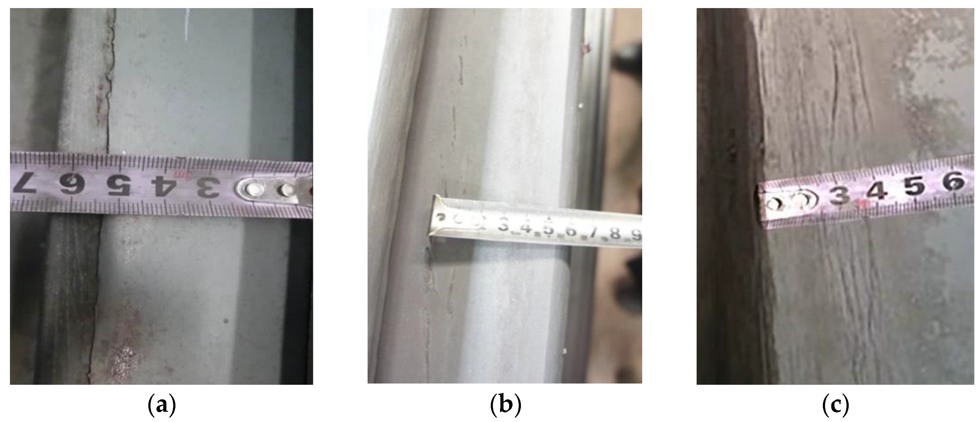
Figure 2.
Formation and inversion of edge creases.

Figure 3.
Schematic diagram of horizontal rolling at the chamfered slab corner.

Figure 4.
Schematic diagram of vertical rolling at the chamfered slab corner.

Figure 5.
Schematic diagram of frontal rolling using a two-roller at the chamfered slab corner.
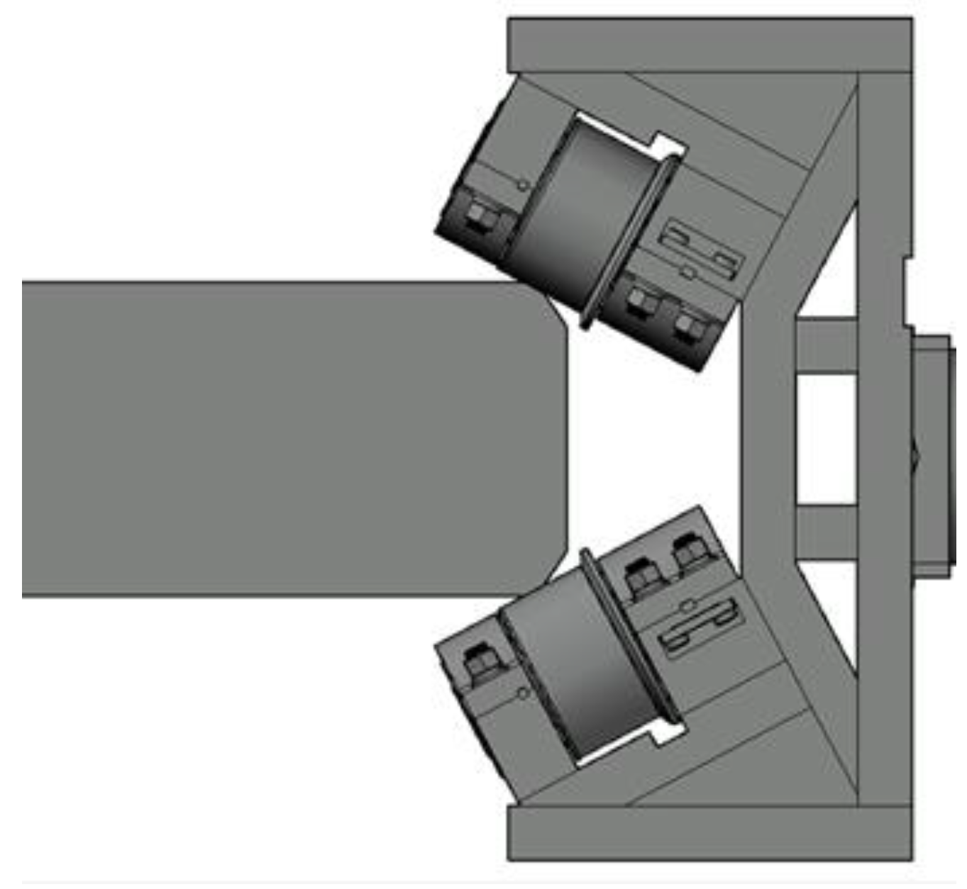
Figure 6.
The geometrical dimensions of four corner-shape slabs: (a) RS; (b) OCS; (c) STCS; (d) LTCS.
Figure 6.
The geometrical dimensions of four corner-shape slabs: (a) RS; (b) OCS; (c) STCS; (d) LTCS.
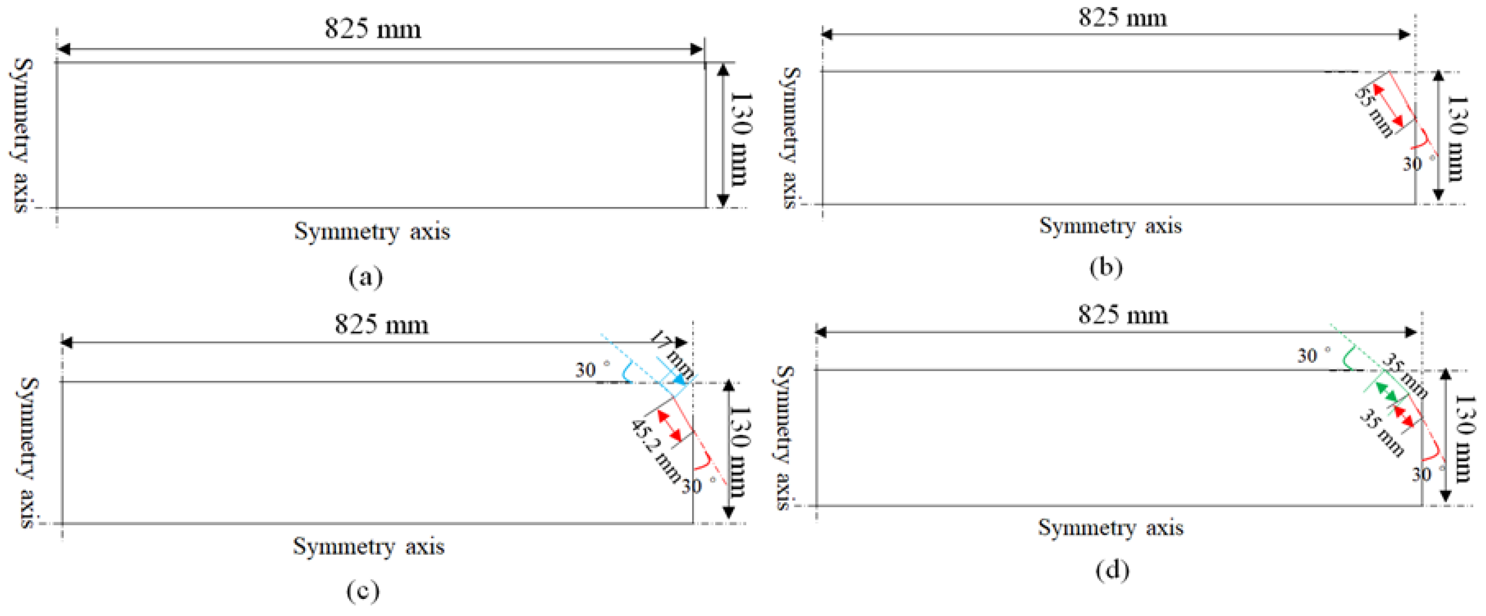
Figure 7.
The model of different rolling methods. (a) Horizontal rolling; (b) vertical rolling; (c) frontal rolling using a two-roller.
Figure 7.
The model of different rolling methods. (a) Horizontal rolling; (b) vertical rolling; (c) frontal rolling using a two-roller.
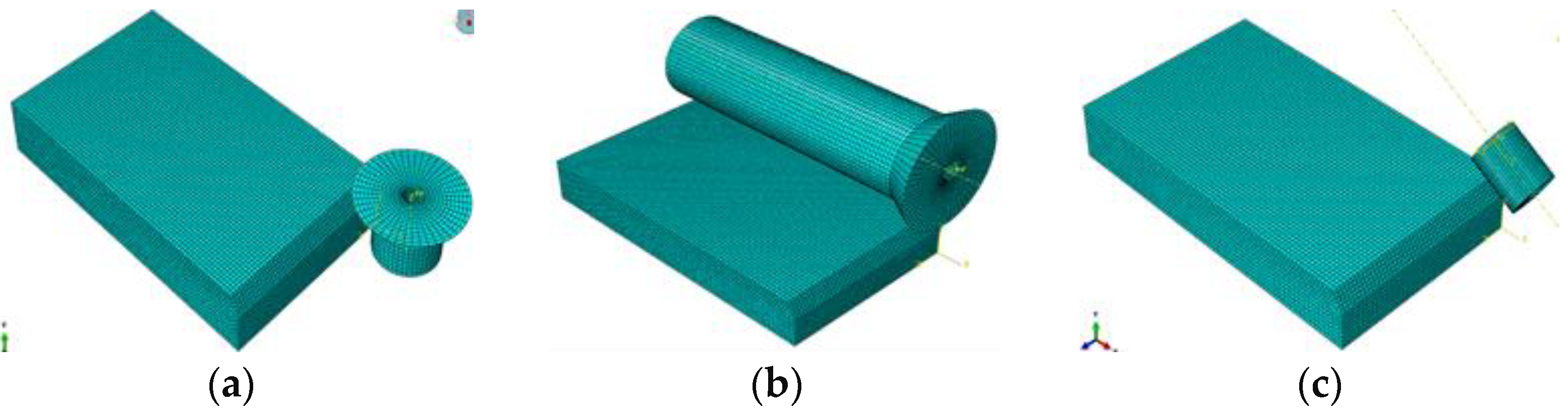
Figure 8.
Enlarged view and the selected nodes along the slab corner before deformation.
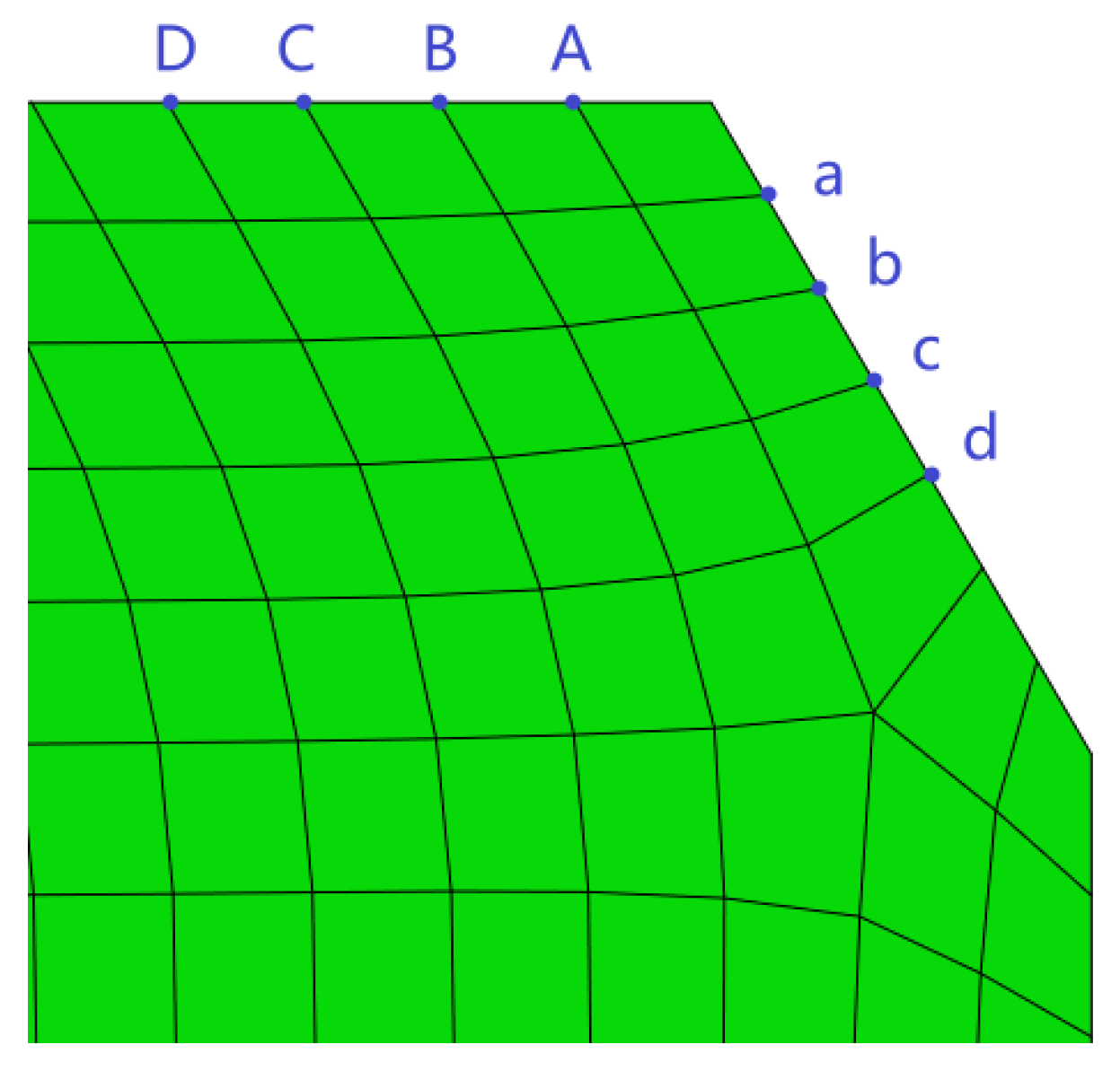
Figure 9.
The physical property data of Q345B. (a) Specific heat; (b) thermal conductivity; (c) Young’s modulus; (d) thermal expansion coefficient.
Figure 9.
The physical property data of Q345B. (a) Specific heat; (b) thermal conductivity; (c) Young’s modulus; (d) thermal expansion coefficient.
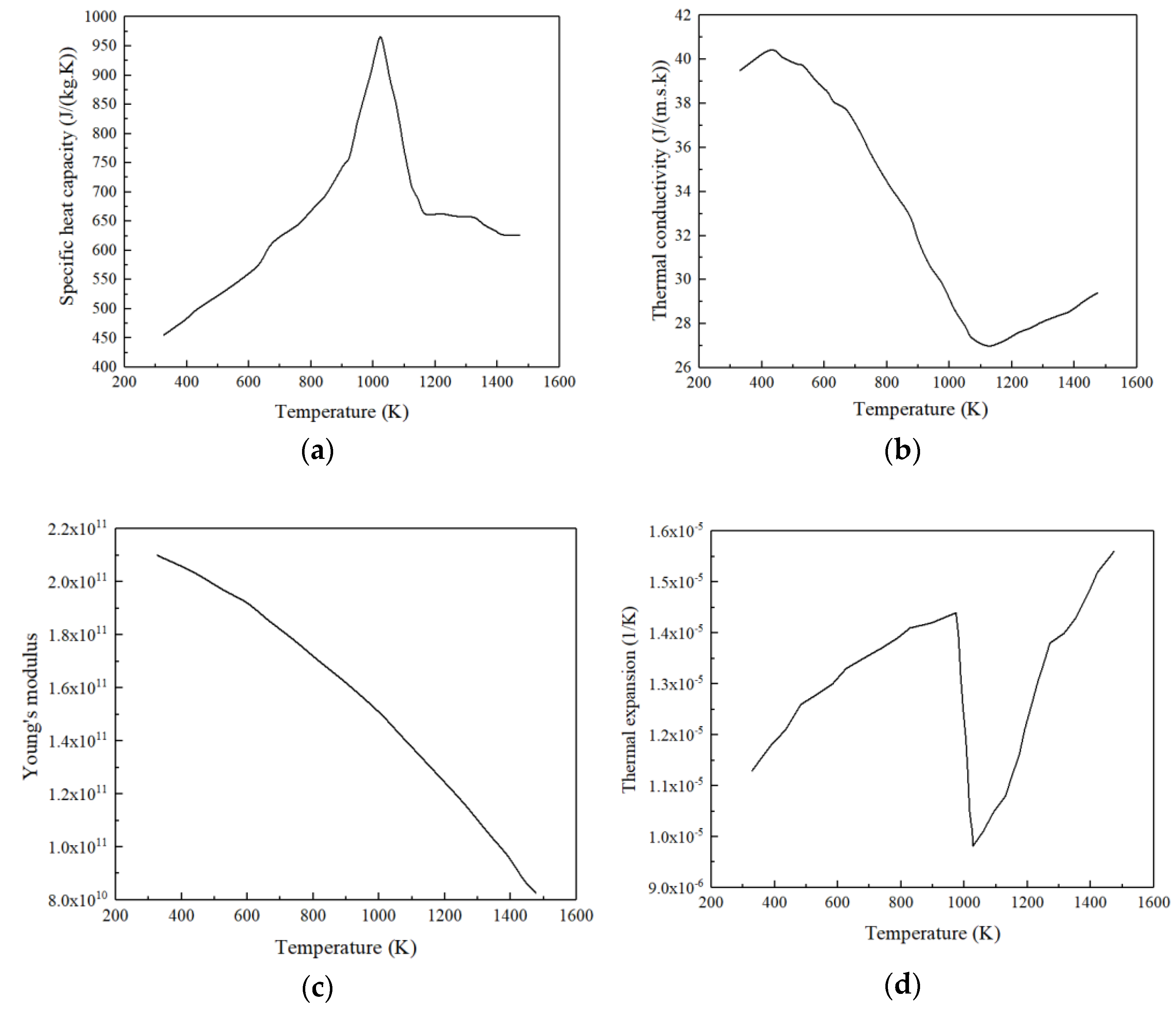
Figure 10.
Temperature distribution of slab corners of different shapes. (a) Right-angle slab; (b) one-chamfered slab; (c) small two-chamfered slab; (d) large two-chamfered slab.
Figure 10.
Temperature distribution of slab corners of different shapes. (a) Right-angle slab; (b) one-chamfered slab; (c) small two-chamfered slab; (d) large two-chamfered slab.

Figure 11.
Temperature distribution at different heights from the narrow face’s center of various shape slabs. (a) Temperature distribution; (b) point designation diagram.
Figure 11.
Temperature distribution at different heights from the narrow face’s center of various shape slabs. (a) Temperature distribution; (b) point designation diagram.

Figure 12.
Deformation of the slab corners under horizontal rolling with a chamfered length of 20 mm.
Figure 12.
Deformation of the slab corners under horizontal rolling with a chamfered length of 20 mm.

Figure 13.
Deformation morphology of the slab corners under vertical rolling with a chamfered length of 20 mm.
Figure 13.
Deformation morphology of the slab corners under vertical rolling with a chamfered length of 20 mm.
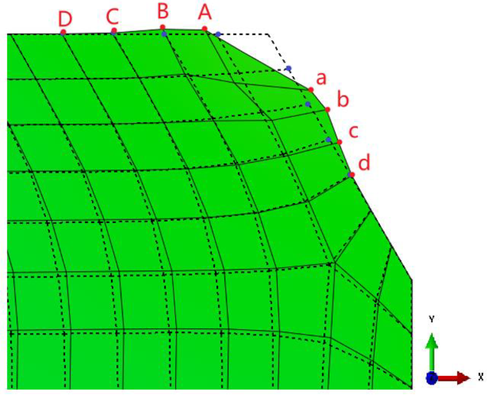
Figure 14.
Deformation morphology of the slab corners under frontal rolling using a two-roller with a chamfered length of 20 mm.
Figure 14.
Deformation morphology of the slab corners under frontal rolling using a two-roller with a chamfered length of 20 mm.

Figure 15.
Stress on a slab corner under two-chamfered rolling process. (a) Horizontal rolling; (b) vertical rolling; (c) frontal rolling using a two-roller.
Figure 15.
Stress on a slab corner under two-chamfered rolling process. (a) Horizontal rolling; (b) vertical rolling; (c) frontal rolling using a two-roller.

Figure 16.
Industrial applications of two-chamfered equipment. (a) Horizontal rolling; (b) frontal rolling with a two-roller.
Figure 16.
Industrial applications of two-chamfered equipment. (a) Horizontal rolling; (b) frontal rolling with a two-roller.
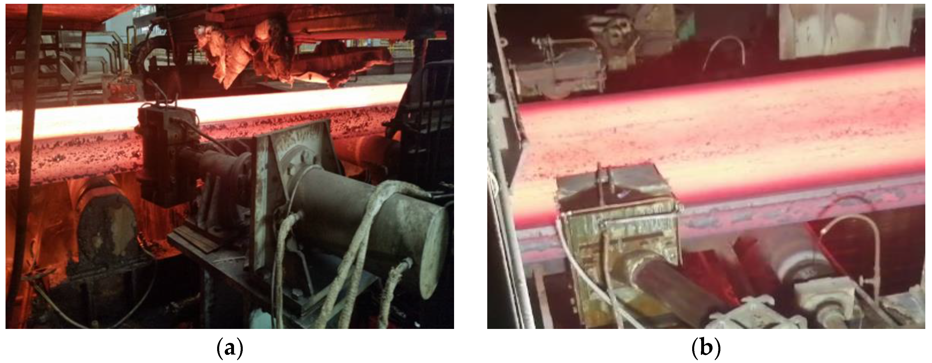
Figure 17.
A two-chamfered shape slab. (a) Hot slab; (b) cold slab.
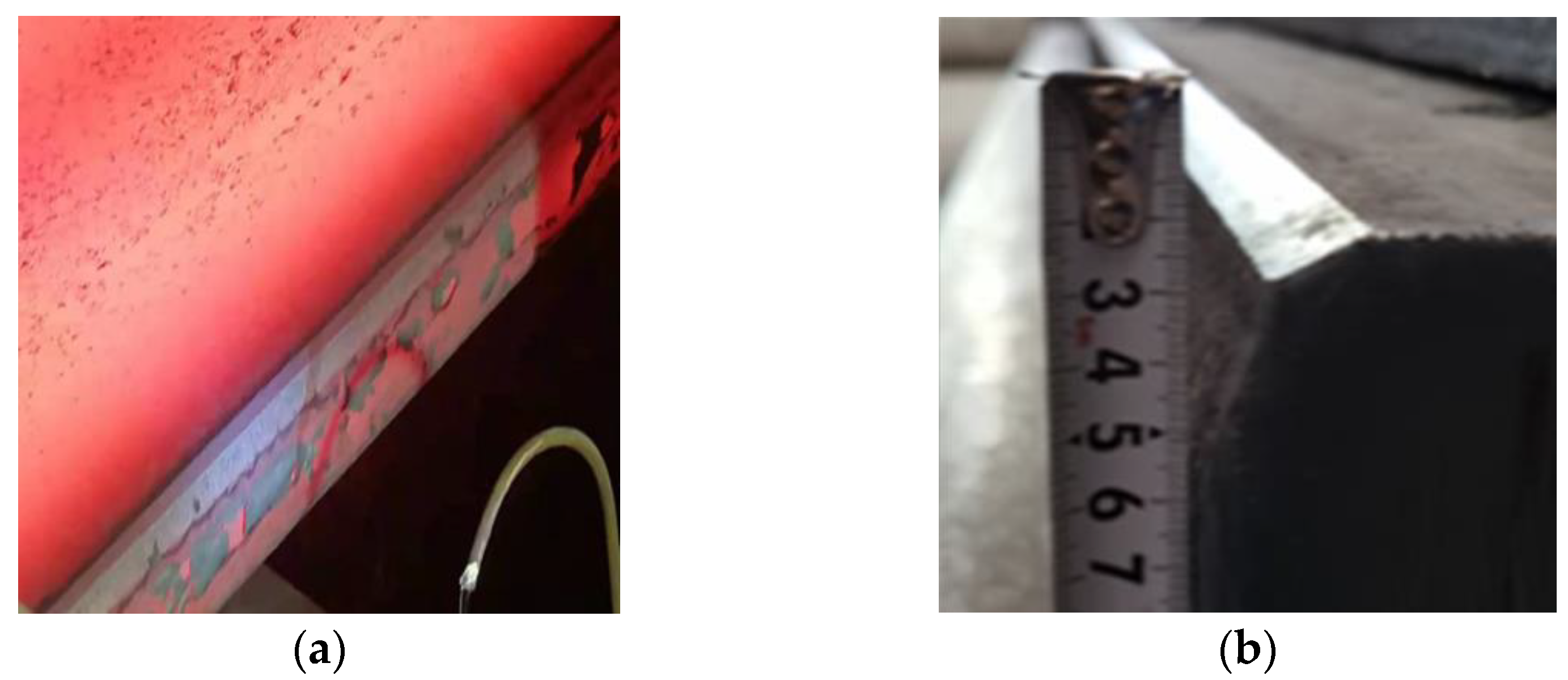
Figure 18.
Typical morphology of an edge seam defect on heavy plates produced by the two-chamfered slab under frontal rolling with a two-roller.
Figure 18.
Typical morphology of an edge seam defect on heavy plates produced by the two-chamfered slab under frontal rolling with a two-roller.

Figure 19.
Small cracks on the slope face of a two-chamfered slab under horizontal rolling.

Table 1.
Required rolling force for different rolling methods. (ton).
| Chamfered Length (mm) | 11 | 14 | 17 | 20 | |
|---|---|---|---|---|---|
| Rolling Methods | |||||
| Horizontal rolling | 20.8 | 31.3 | 43.1 | 53.2 | |
| Vertical rolling | 21.8 | 32.8 | 45.3 | 54.0 | |
| Frontal rolling using a two-roller | 18.6 | 29.6 | 40.4 | 48.6 | |
Table 2.
Rolling resistance for different rolling methods. (ton).
| Chamfered Length (mm) | 11 | 14 | 17 | 20 | |
|---|---|---|---|---|---|
| Rolling Methods | |||||
| Horizontal rolling | 5.9 | 7.9 | 11.2 | 18.6 | |
| Vertical rolling | 6.1 | 9.3 | 13.4 | 19.0 | |
| Frontal rolling using a two-roller | 5.6 | 8.0 | 11.0 | 18.2 | |
Table 3.
Node deformation at different two-chamfered lengths under horizontal rolling (mm).
| Two-Chamfered Length(mm) | Direction | A | B | C | D | a | b | c | d |
|---|---|---|---|---|---|---|---|---|---|
| 11 | X | −3.40 | −0.10 | −0.01 | 0.01 | 1.30 | −0.01 | 0.09 | 0.02 |
| Y | 1.68 | 0.12 | 0.03 | 0.01 | −0.55 | 0.04 | −0.004 | 0.01 | |
| 14 | X | −4.60 | −0.70 | −0.12 | −0.004 | 1.40 | 0.07 | 0.09 | 0.03 |
| Y | 2.10 | 0.67 | 0.09 | 0.01 | −0.70 | 0.01 | −0.02 | 0.01 | |
| 17 | X | −6.12 | −1.90 | −0.77 | −0.01 | −0.13 | 0.13 | 0.07 | 0.03 |
| Y | 2.80 | 1.70 | 0.58 | 0.01 | −0.80 | 0.01 | −0.02 | −0.004 | |
| 20 | X | −7.90 | −3.4 | −1.8 | −0.08 | −1.63 | 0.16 | 0.08 | 0.05 |
| Y | 3.50 | 2.80 | 1.44 | 0.07 | −0.96 | −0.01 | −0.01 | −0.004 |
Table 4.
Node deformation at different two-chamfered lengths under vertical rolling (mm).
| Two-Chamfered Length (mm) | Direction | A | B | C | D | a | b | c | d |
|---|---|---|---|---|---|---|---|---|---|
| 11 | X | −1.67 | 0.04 | −0.04 | 0.02 | 3.11 | 0.16 | 0.21 | 0.03 |
| Y | 1.22 | 0.04 | 0.05 | 0.005 | −1.55 | −0.006 | −0.05 | 0.003 | |
| 14 | X | −2.10 | 0.13 | −0.13 | 0.01 | 3.50 | 0.58 | 0.40 | 0.03 |
| Y | 1.70 | 0.16 | 0.10 | 0.004 | −2.1 | −0.01 | −0.16 | −0.01 | |
| 17 | X | −2.30 | 0.01 | −0.23 | −0.004 | 3.90 | 1.57 | 1.03 | 0.10 |
| Y | 1.80 | 0.28 | 0.15 | 0.02 | −2.94 | −0.33 | −0.31 | −0.02 | |
| 20 | X | −2.30 | −0.5 | −0.27 | −0.04 | 4.32 | 3.50 | 1.82 | 0.34 |
| Y | 0.74 | 1.00 | 0.20 | 0.05 | −4.25 | −1.00 | −0.54 | −0.09 |
Table 5.
Node deformation of different two-chamfered lengths under frontal rolling using a two-roller (mm).
Table 5.
Node deformation of different two-chamfered lengths under frontal rolling using a two-roller (mm).
| Two-Chamfered Length (mm) | Direction | A | B | C | D | a | b | c | d |
|---|---|---|---|---|---|---|---|---|---|
| 11 mm | X | −1.94 | 0.04 | −0.04 | 0.02 | 2.30 | 0.06 | 0.13 | 0.03 |
| Y | 1.19 | 0.04 | 0.04 | 0.01 | −1.08 | 0.02 | −0.03 | 0.01 | |
| 14 mm | X | −2.6 | 0.03 | −0.07 | 0.01 | 2.88 | 0.06 | 0.18 | 0.01 |
| Y | 1.50 | 0.06 | 0.05 | 0.01 | −1.58 | −0.01 | −0.06 | −0.01 | |
| 17 mm | X | −3.2 | −0.04 | −0.39 | −0.003 | 2.57 | 0.92 | 0.59 | 0.05 |
| Y | 2.30 | 0.45 | 0.25 | 0.016 | −2.11 | −0.04 | −0.16 | −0.01 | |
| 20 mm | X | −3.79 | −0.93 | −0.44 | −0.02 | 2.66 | 2.0 | 0.99 | 0.10 |
| Y | 2.09 | 1.16 | 0.31 | 0.04 | −2.70 | −0.36 | −0.27 | −0.02 |
Publisher’s Note: MDPI stays neutral with regard to jurisdictional claims in published maps and institutional affiliations. |
© 2022 by the authors. Licensee MDPI, Basel, Switzerland. This article is an open access article distributed under the terms and conditions of the Creative Commons Attribution (CC BY) license (https://creativecommons.org/licenses/by/4.0/).
Share and Cite
MDPI and ACS Style
Wang, M.; Zhang, H.; Zhao, W.; Liu, H.; Wang, X. Application of Optimizing Slab Corner Shapes to Reduce Edge Seam Defect on Heavy Plates. Metals 2022, 12, 1984. https://doi.org/10.3390/met12111984
AMA Style
Wang M, Zhang H, Zhao W, Liu H, Wang X. Application of Optimizing Slab Corner Shapes to Reduce Edge Seam Defect on Heavy Plates. Metals. 2022; 12(11):1984. https://doi.org/10.3390/met12111984
Chicago/Turabian StyleWang, Minglin, Hui Zhang, Wenbo Zhao, Heping Liu, and Xuebing Wang. 2022. "Application of Optimizing Slab Corner Shapes to Reduce Edge Seam Defect on Heavy Plates" Metals 12, no. 11: 1984. https://doi.org/10.3390/met12111984
Note that from the first issue of 2016, this journal uses article numbers instead of page numbers. See further details here.