
Effects of Simulated PWHT on the Microstructure and Mechanical Properties of 2.25Cr1Mo0.25V Steel for a Hydrogenation Reactor

1
The State Key Laboratory of Rolling and Automation, Northeastern University, Shenyang 110819, China
2
Hunan Valin Xiangtan Iron and Steel Co., Ltd., Xiangtan 411101, China
*
Author to whom correspondence should be addressed.
Metals 2022, 12(11), 1978; https://doi.org/10.3390/met12111978
Submission received: 3 October 2022
/
Revised: 13 November 2022
/
Accepted: 16 November 2022
/
Published: 19 November 2022
(This article belongs to the Special Issue Advanced Technology in Microalloyed Steels)
Abstract
:The effect of post-welding heat treatment (PWHT) on the microstructure and mechanical properties of large-thickness 2.25Cr1Mo0.25V steel was investigated through simulated post-welding heat treatment (SPWHT). The results showed that an increase in the SPWHT time decreased the toughness, hardness, and strength of the steel. After Min.SPWHT, the high-temperature tensile strength decreased more significantly, and the damage of Min.SPWHT to the high-temperature tensile strength reached approximately 80% of the Max.SPWHT. The microstructure of the tested steel before and after SPWHT consisted of granular bainite and lath bainite. After SPWHT, intergranular carbides were precipitated as coarsened carbides, carbide clusters, and chains of carbides; alloy element segregation occurred, and the segregation of Mo was the most serious, followed by Cr, and V. The precipitation behavior of the carbides and the increase in the effective grain size caused by the widening of the bainite–ferrite lath worked together and resulted in the decline of the impact toughness; the reduction in the solid solution and precipitation strengthening effects were the main factors in the strength reduction of the tested steel. In the high-temperature tensile tests, defects first appeared around the coarse carbides and carbide clusters. Controlling the size of the intergranular large-size carbides and the degree of cluster precipitation in the NT state structure may be a means of obtaining higher strength of the base metal subjected to PWHT.
1. Introduction
A hydrogenation reactor is a major piece of equipment used in the field of energy-intensive processing, such as petroleum cracking and coal liquefaction [1]. Due to long-term service in a high-temperature and high-pressure hydrogen environment, the performance requirements of the steel used are strict. Low-alloyed 2.25Cr1Mo0.25V steel is typically used in hydrogen-bearing heavy wall pressure vessels in the petrochemical industry [2]. Compared with traditional Cr–Mo steel, the addition of vanadium and micro-alloy elements in 2.25Cr1Mo0.25V steel improves the hardenability and strength grade of the steel; this steel has better high-temperature creep resistance, tempering embrittlement resistance, hydrogen corrosion resistance, hydrogen embrittlement, and hydrogen-induced crack resistance [3].
2.25Cr1Mo0.25V steel is usually strengthened by using two methods to improve its mechanical properties at high temperatures. One method utilizes the solid solution of Cr and Mo to strengthen the matrix [4]. The other method forms fine precipitates produced by adding micro-alloying elements, such as V, Nb, and Ti; these comprise a cubic crystal structure of type MX and can effectively hinder the dislocation movement [5,6]. The addition of V, Nb, and Ti result in low toughness after welding [7]. Therefore, the steel requires a strict welding process and post-weld heat treatment (PWHT) procedure. Its main purpose is to improve the microstructure and properties of the welded joint, soften the hardened zone, and increase the toughness and lasting creep limit [8]. PWHT can relax or eliminate the welding stress, prevent the generation and propagation of delayed cracks, and improve the service reliability and service life of the welded joint [9,10]. Because after welding, the whole or part of the reactor will be subject to post-weld heat treatment, the base metal (the steel plate used as the container wall) around welded joints also is subjected to the same ineluctable heat treatment process; this results in a change in the performance of the base metal [11]. In order to know the change in mechanical properties of the base metal after PWHT in advance and ensure that the mechanical properties of the base metal can still meet the design requirements after a long time of heat treatment, the buyer will require the supplier to conduct simulated post-weld heat treatment (SPWHT) on the steel plates or forgings and provide experimental results before delivery. This situation is common in the field of steel pressure vessel manufacturing.
According to 2013 ASME Boiler & Pressure Vessel Code Ⅱ MATERIALS, a variety of experimental tests listed in the supplementary requirements may be performed with agreement between the plate supplier and the purchaser. The specified tests should be conducted by the plate supplier and the test results should be provided before shipment of the plates. Simulated post-weld heat treatment of mechanical test coupons is one of the listed tests. In this part, the test coupons representing the plate for acceptance purposes of the mechanical properties is thermally treated by the plate supplier to simulate a post-weld heat treatment below the critical temperature (Ac3), using the heat treatment parameters (such as temperature range, time, and cooling rates) specified in the purchase order [12]. The test results must meet the requirements of the applicable product specification. Similar content is also mentioned in HG/T 20584-2011 Specification of design base for steel chemical vessels and GB/T 35012-2018 Chromium molybdenum alloy steel plate for hydrogen service equipment. At present, the performance of steel plate after SPWHT has been considered as a necessary index by purchasers in the transaction of steel plates for large-thickness pressure vessels (such as 2.25Cr1Mo0.25V steel).
The two concepts of SPWHT and PWHT are distinguished here. The heat treatment procedure of SPWHT is the same as that of PWHT. The difference between the two is that SPWHT is carried out on the steel plate as delivered and used to judge whether the performance of the base metal subjected to PWHT meets the requirements of the overall structural strength of the pressure vessel; the PWHT is aimed at the welding zone and heat affected zone of welded joint to improve their microstructure and mechanical properties. SPWHT can be regarded as a preliminary inspection of steel welding performance. If the mechanical properties of the steel plate subjected to SPWHT do not meet the standard, it is meaningless to continue the welding tests.
Specifically, SPWHT simulates the sum of all PWHTs experienced by the equipment in the manufacturing process [13]. Normally, minimum SPWHT (Min.SPWHT) and maximum SPWHT (Max.SPWHT) are included in SPWHT with a difference in duration among them. In practice, the Min.SPWHT simulates the heat treatment procedure required to eliminate residual stress after welding and recover the performance of the welded joints for container forming, and its time is determined according to the thickness of steel plate [14]. The Max.SPWHT simulates the heat treatment procedure required for post-welding stress relief after container forming and repairs (generally considering two repairs), and its duration depends on the possible number of repairs [13,15,16]. According to the national standard GB/T 35012-2018 Chromium molybdenum alloy steel plate for hydrogen service equipment, the SPWHT test of 2.25Cr1Mo0.25V steel used for a hydrogenation reactor is carried out at 705 °C for the duration determined in consultation with the factory and the buyer, and generally the Min.SPWHT and Max.SPWHT is conducted for 6–10 h and 26–40 h, respectively [17,18,19].
Before welding tests, it is of great practicality and convenience to study the effects of PWHT on the base metal by carrying out SPWHTs, and the reactor manufacturers can easily and quickly obtained the mechanical property index of the base metal after PWHT without welding experiments. Previous studies [8,9,11,14,15,20,21] concerning SPWHT conducted by steel plate suppliers paid more attention to the changes in the mechanical properties of the base metal after PWHT. The change mechanism in the microstructure and mechanical properties in this process have not been fully revealed, and the degree of damage of using two post-weld heat treatment systems on the steel plate’s properties has not been clarified. Currently, it is the subject of most research to determine the welding performance and feasibility of the welding process of steel plates by studying the microstructure and mechanical properties of the welded joints after PWHT. These studies [7,16,22,23] mainly focused on changes in the weld zone and heat affected zone and paid little attention to changes in the base metal after PWHT. Furthermore, with the increasing size and power of hydrogenation reactors, the thickness of vessel wall steel plate is increasing continuously. One of the difficulties in the production of large-thickness 2.25Cr1Mo0.25V steel plate is that after high-temperature and long-time PWHT, the steel plate is prone to performance fluctuations, strength reduction, and a greater difficulty in performance assurance [24], making it difficult for suppliers to control the properties of the as-received plate. Therefore, it is necessary to study the structure and mechanical properties of the base metal of 2.25Cr1Mo0.25V steel after PWHT through SPWHT to understand the damage mechanisms of PWHT and provide a theoretical basis for producing plates with excellent post-weld properties.
This study used a 150 mm thick 2.25Cr1Mo0.25V steel plate in a normalized and tempered state as the sample. In this research, the effects of PWHT on the microstructure and mechanical properties of 2.25Cr1Mo0.25V steel were investigated through SPWHT; the relationship between the microstructure and mechanical properties was analyzed to improve researchers’ understanding of how PWHT affects base metals; methods to improve the properties of the microstructure subjected to SPWHT were explored to provide a theoretical basis for high-performance steel plate development in industrial production.
2. Materials and Methods
The tested material was a 150 mm thick 2.25Cr1Mo0.25V steel plate prepared by Hunan Valin Xiangtan Iron and Steel Co Ltd. The heat treatment consisted of normalizing at 960 °C min/mm and tempering at 730 °C min/mm, the procedure commonly adopted in the practical industry. The chemical composition of the 2.25Cr1Mo0.25V steel is listed in Table 1. Its mechanical properties are shown in Table 2. For convenience, “NT” is used to represent as-receive steel in the following content.
The sample sizes for SPWHT were 150 × 120 × 240 mm (thick×width×length). At the purchaser’s request, The SPWHT procedure used a temperature of 705 °C for 8 h (represented by Min.SPWHT) and 705 °C for 32 h (represented by Max.SPWHT). The samples were heated to 400 °C with a furnace; they were then ramped up to 705 °C at a heating rate of 55 °C/h. After holding for a certain time, the specimens were cooled to 400 °C at the rate of 55 °C/h and discharged for air cooling. The mechanical properties of the specimens in the NT and SPWHT states were tested. Since a hydrogenation reactor is used at high temperatures, high-temperature tensile tests at 450 °C, 500 °C, and 550 °C were used to evaluate the high-temperature properties of the experimental steel. The microstructure was observed and characterized using a metallographic microscope, a scanning electron microscope (SEM), an electron microprobe, and a transmission electron microscope (TEM).
For the mechanical property tests, the hardness was measured using a KB3000BURZ-SA hardness tester using a 20 N load. The impact test specimens were standard Charpy V-notch specimens; the impact tests were conducted at −30 °C with a ZBC2452-B pendulum impact tester. Using GB/T228.1–2010, a standard room temperature transverse tensile specimen with a parallel section diameter of 5 mm was prepared; the tensile speed was 2 mm/min. Using GB/T228.2–2015, a high-temperature transverse tensile specimen with a parallel section diameter of 6 mm was prepared; the tensile speed was 0.5 mm/min. The tensile test was performed with a GOTECH AI-7000-LAU tension tester. For the microstructure observation experiments, the polished samples were etched with 4 vol.% Nital to prepare the metallographic samples. The microstructure of the experimental steel molds before and after SPWHT was examined using an OLYMPUS BX53M optical microscope and an Ultra55 field emission scanning electron microscope. The element distribution was analyzed by a JEOL JXL-8530f field emission electron probe microanalyzer (EPMA). The micro-characteristics of the precipitates, laths, and dislocations were examined using a TECNAI G2 F20 TEM. The high-temperature tensile fracture surface examination was conducted using an FEI Quenta600 tungsten filament SEM. The sampling position and analysis method of the sample are shown in Figure 1.
3. Results
3.1. Mechanical Properties
The results from the mechanical property tests are listed in Figure 2. It was found that all mechanical properties of the 2.25Cr1Mo0.25V steel after SPWHT met the standards. The hardness of the NT state steel was approximately 233 HV; when the SPWHT times were 8 h and 32 h, the corresponding hardness was approximately 223 HV and 212 HV, respectively. When the SPWHT time increased from 0 h to 8 h, the impact energy reduced from 274 J to 263 J. As the SPWHT time continued to increase, the impact energy continued to decrease and reduced to 192 J at the SPWHT time of 32 h.
As shown in Figure 2c,d, with the increase in SPWHT duration, the steel strength gradually declined. After Max.SPWHT, the room-temperature strength changed almost as much as the high-temperature strength. The damage of the Min.SPWHT to the high-temperature strength was greater than the room-temperature strength, and the damage of Min.SPWHT to the high-temperature tensile strength of steel plate reached approximately 80% of the Max.SPWHT. For example, compared with the steel in the NT state, the tensile strength decreased sharply from 546 MPa to 487 MPa at an SPWHT time of 8 h, and then decreased to 484 MPa at an SPWHT time of 32 h. This showed that the influence of the microstructural change on the high-temperature strength reached a very-high level at an SPWHT time of 8 h.
3.2. Microstructure Analysis
The microstructure of the 2.25Cr1Mo0.25V steel in the NT state (as-receive state) consisted of granular bainite and lath bainite with an average grain size of 21.3 μm, shown in Figure 3. The fine carbides such as VC were precipitated dispersedly in the intracrystalline structure, and many large-size carbides appeared at the grain boundary.
Figure 4 depicts the microstructure of the 2.25Cr1Mo0.25V steel subjected to SPWHT. After SPWHT, there was no obvious change in grain size. Due to the degradation of lath by long-time SPWHT, the lath of bainite widened and the amount of lath bainite decreased with an increase in the amount of granular bainite (Figure 4b,e). Compared with the NT state, the number of precipitates in the Min.SPWHT state increased; the precipitates were mainly granular, spherical, and rod-shaped, and more carbides precipitated at the grain boundary (Figure 4c). In the Max.SPWHT state, some carbides precipitated in chains or stacked together to form carbide clusters; the number of rod-shaped precipitates decreased; there were evident spheroidization and coarsening phenomena of the precipitates (Figure 4f).
3.3. Precipitates
The precipitates in the microstructure were further examined by TEM, shown in Figure 5. Coarsened precipitates and chains composed of precipitates in the Max.SPWHT state steel were observed, as shown in Figure 5d,e. The statistical data on the size distribution of the precipitates confirmed the coarsening phenomenon of the precipitates, shown in Figure 6. The average size of the intragranular carbides increased from 21.1 nm at the NT state to 63.2 nm at the Max.SPWHT state, while that of the intergranular carbides increased from 93.2 nm to 160.5 nm. Specifically, 83.3% and nearly 50% of the precipitates in the grain interior in the NT state steel were within a size range of 10–30 nm and 10–20 nm, respectively; 91.6% of those in the Max.SPWHT steel were within the size range of 10–100 nm with a small proportion of fluctuation in each size range. Furthermore, 94.6% and nearly 60% of the precipitates at the grain boundary in the NT state steel were within the size range of 20–100 nm and 20–40 nm, respectively, with a maximum size of 100 nm; 79.8% of those in the Max.SPWHT state steel were within the size range of 20–100 with a maximum size of 250 nm. During SPWHT, more carbides precipitated at the grain boundary, and the coarsening phenomenon of the intragranular carbides was more evident than that in the grain interior. Due to the high free energy at the grain boundary, atom diffusion occurred more easily; the precipitated phases at the grain boundary were easier to develop. Furthermore, Figure 5c,f shows the degradation of the laths and the reduction in the dislocation density in the Max.SPWHT state.
3.4. Element Distribution
The effect of the SPWHT on the distribution of the main alloy elements of Cr, Mo, and V was studied by EPMA and is depicted in Figure 7. There was no clear difference in the distribution of V in the tested steel before or after SPWHT, see Figure 7(a5–c5). After SPWHT, the segregation of Cr and Mo gradually deepened with the precipitation and growth of the carbides; this resulted in a decrease in the content of solid solution elements in the matrix. As shown in Figure 7(a4–c4), the segregation degree of Mo in the grain interior was the highest, and it existed almost exclusively in the intergranular carbides after Max.SPWHT. Furthermore, the exact change of the alloy element content was measured by EDS as shown in Figure 8. Figure 9 depicts the position of the measured points and they are set on the matrix and grain boundary carbide, respectively. The content of Mo in the matrix gradually decreased from 0.16 wt% to 0.05 wt% at the SPWHT time of 8 h, and then decreased to 0.00 wt% at the SPWHT time of 32 h. Consequently, for the intergranular carbides, the Mo content increased from 0.11 wt% to 0.13 wt%, and then increased to 0.25 wt%, and the content of other elements forming carbide also increased, such as Cr, V, Mn. Combining the EDS and EPMA results, when only considering the Cr, Mo and V elements, found that the large-size carbides in the 2.25Cr1Mo0.25V steel after SPWHT included Cr–Mo–V-rich carbides, Cr-rich carbides, Cr-Mo-rich carbides, and fewer Mo-rich carbides (Figure 7(c2–c5)).
3.5. Fracture Morphology of High-Temperature Tensile Samples
The fracture morphology of the high-temperature tensile samples was investigated using SEM. All fractures possessed cup-cone-shaped morphology with evident necking, such as fractured surface of the 550 °C tensile specimen subjected to Max.SPWHT shown in Figure 10a. Figure 10b shows the reduction rate of the area of the specimen after the high-temperature tension test. It was found that the plasticity of the steel in the Min.SPWHT state was optimal. When the SPWHT time exceeded 8 h, plasticity presented different changing trends at different temperatures; it hardly changed at 550 °C and dropped sharply at 450 °C. Specifically, when the SPWHT time of the sample was increased from 8 h to 32 h, the area reduction in the sample stretched at 450 °C decreasing from 51.4 to 32.1%, whereas the stretched sample at 550 °C was almost unchanged and only showed a very slight decrease from 67.5 to 66.6%. Figure 11 shows the micro-morphology of the fracture of the high-temperature tension samples, and all surfaces showed typical dimple fractures. It was found that the better the plasticity of the sample, the higher the proportion of large dimples on the fracture surface (Figure 11d–f) [25]. Some precipitated particles were found at the bottom of the dimples (Figure 11b,c,e,h). Furthermore, some micro-voids existed at the bottom of the dimples and some particles appeared at the edge of the micro-void (Figure 11c,e). The dimple sources may be large-sized carbide particles: in the areas with poor plasticity, dimples were formed around carbide particles; in the areas with good plasticity, in addition to dimples, micro-voids were also formed around carbide.
It is well known that tempering to a certain extent can improve the plasticity and toughness of steel; at a higher temperature or after tempering for a long time the plasticity of steel declines, which is called temper embrittlement. In this study, the structure after Min.SPWHT was in a reasonable tempering degree, while the structure after Max.SPWHT appeared temper embrittlement and showed poor plasticity, which may be caused by the coarsening of precipitates, element segregation, etc. [26].
3.6. Cavity Nucleation in High-Temperature Tensile Samples
Figure 12 shows the SEM images of the necking area of the high-temperature tensile samples using the Max.SPWHT time. The microstructure deformed along the stretching direction. A large number of cavities formed at the interface of the deformation and then expanded along the tensile direction. Relevant studies showed that the fracture at high temperatures was a continuous hole fracture, and the formation of the dimples was a result of the connection of the cavities. Nucleation in the cavity was easier around the large, precipitated phase at the grain boundary during tensile testing. The sliding deformation of the grain boundary was hindered by the coarse precipitated phase at high temperatures; this resulted in a serious stress concentration and made it easier to reach the driving force of nucleation of the cavities [27]. The interface bonding strength between non-coherent precipitates and the matrix was lower; this interface was favorable for nucleation of the cavities.
3.7. Precipitates in the Microstructure of High-Temperature Tensile Samples
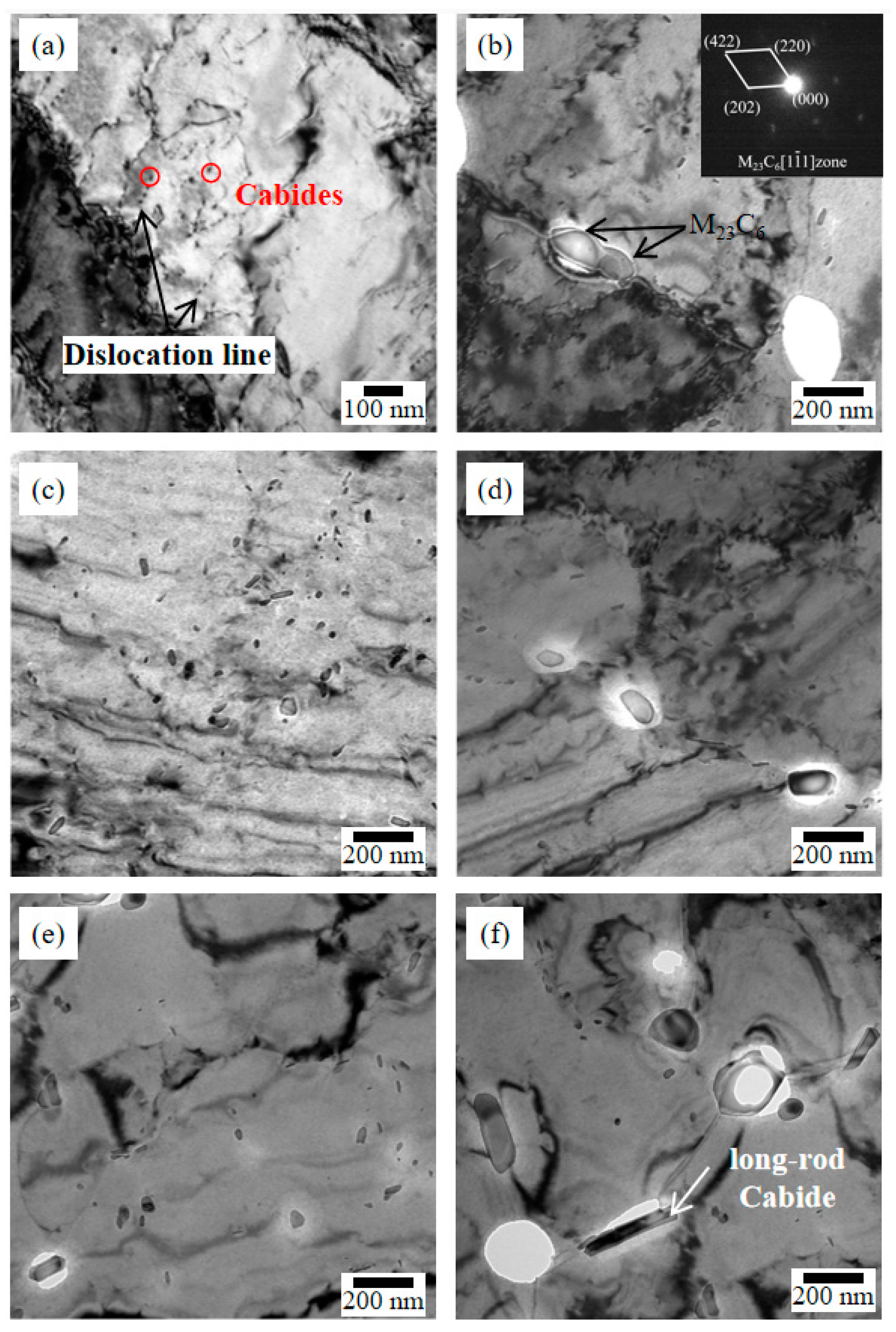
TEM pictures of the precipitates in the necking area of the high-temperature tensile samples are shown in Figure 13. A large number of dislocations was generated in the necking area after stretching, and many small carbides nucleated on the dislocation lines (Figure 13a). With an increase in the tensile temperature, the size of these small carbides gradually increased (Figure 13c,e). In the grain boundary of the 450 °C and 500 °C tensile samples, the large precipitates, such as M23C6, were mainly spherical and ellipsoidal (Figure 13b); spherical and long-rod precipitates at the grain boundary of the 550 °C tensile samples were larger in size (Figure 13b,d,f). During stretching, the higher temperature promoted nucleation and coarsening of the precipitates in the deformation zone. The coarsened precipitates accelerated the nucleation of the cavities, promoted continuous-hole fractures, and led to a decrease in strength.
4. Discussion
With an increase in the SPWHT time, there was a reduction in the hardness, the −30 °C impact toughness, and the strength. Hydrogen-related properties are important indicators of hydrogen-bearing steel. Asahi et al. [28] showed that the vanadium carbide formed was the main reason for the improvement observed in hydrogen resistance in the vanadium-added steel. He et al. [29] investigated the hydrogen absorption ability of metal carbides in 2.25Cr1Mo and 2.25Cr1Mo0.25V steels using density functional theory calculations; they found that vanadium carbides showed a better hydrogen absorption performance than chromium carbides and molybdenum carbides. There are few studies on the change of the hydrogen damage resistance after SPWHT. Due to the lack of experimental resources, research on hydrogen-related properties was not part of this study.
This study focused on the precipitation behavior of the carbides. Generally, the precipitates in the 2.25Cr1Mo0.25V steel in the NT state included M7C3, M23C6, MC, and M2C; among them, M23C6 became mature and coarsened easily [29,30]. In this study, coarsening carbides, carbide clusters, and chains of carbides formed at the grain boundary of the specimen subjected to SPWHT (Figure 4f). Jiang et al. [31] showed that uniformly dispersed fine carbides reduced the stress concentration and improved the impact toughness of the sample. Conversely, large-size carbides and carbide clusters in the grain boundary easily caused stress concentration and cracking. The widening of the bainite–ferrite lath also weakened the ability to prevent crack growth. So it could be considered that the precipitation behaviors of the carbides and the increase in effective grain size caused by the widening of the bainite–ferrite lath worked together and resulted in the decline of the impact toughness of the sample subjected to Max.SPWHT [31,32].
In steels exposed to a creep service environment, solution strengthening and precipitation strengthening are the main strengthening mechanisms that can effectively block the dislocation movement [33,34]. 2.25Cr1Mo0.25V steel mainly strengthened the matrix in the following two ways. In the first method, the matrix is strengthened by adding Cr, Mo, and other solid solution elements to affect the lattice distortion, atomic bond bonding force, and diffusion coefficient of the matrix [35]. There is a disadvantage in preventing the dislocation movement through solution strengthening. The effect of solution strengthening decreases with an increase in temperature; especially under high-temperature conditions, thus its stability is weak [36]. Shi et al. [37] showed that compared with α-Fe, the alloy elements of Cr and Mo dissolved in the matrix can improve the atomic bond attraction of the solid solution; reporting the improvement using Mo was greater than that of Cr. With an increase in temperature, the bond strength of the structural α-Fe-Cr unit and α-Fe-Mo unit decreased. The second method involves using fine carbon nitrides formed by adding V, Nb, Ti, and other micro-alloying elements; these are dispersed within the matrix and can effectively impede the dislocation movement, slow the dislocation creep, and improve the creep strength [7].
From the comparative observation of the steel before and after SPWHT, the segregation of Cr and Mo during the SPWHT process greatly reduced the solid solution amount of the alloy elements in the matrix and weakened the effect of solid solution strengthening. The EPMA results showed that the segregation of Mo was most serious, followed by Cr; V was almost unchanged. During the precipitation and coarsening of the carbides, the strengthening elements, such as Cr, Mo, and V, segregated from the matrix to the carbides; this applied especially to Mo, which was primarily distributed on the carbides in the grain boundary of the sample subjected to Max.SPWHT. From the electronic theory analysis, the bond energy of α-Fe-Me (Me-mix element) was lower than that of α-Fe and the Mo unit < V unit < α-Fe unit; in the α-Fe-Me unit, the destruction of the C bond caused a loss of support and connection between Me and Fe’s primary key; this resulted in an extreme dilution of Mo, followed by Cr and V [38]. Since Mo improved the atomic bond attraction of the solid solution more than Cr and its segregation was most serious, segregation of Mo possibly caused the decrease in the solution strengthening effect. However, it was found from the element content tested by EDS that the content of Mo in the matrix was relatively low, and it decreased from 0.16 wt% to 0.05 wt% at an SPWHT time of 8 h, and then decreased to 0.00 wt% at an SPWHT time of 32 h; it is doubtful whether this reduction in content has a great impact on the strength. Considering the factors of carbide coarsening, matrix dislocation density, and lath structure, Mo segregation was one of the reasons for strength reduction, but it was not a major factor. After the long-time heat treatment of the steel, the coarsening of the precipitates in the grain interior reduced the ability to hinder the movement of the dislocations; this resulted in a reduction in precipitation strengthening; a reduction in the dislocation density and an increase in lath width working together causing a softening effect; this further reduced the strength of the tested steel [39]. During SPWHT, since the hardness index that reflects the tempering softening degree did not noticeably change, the reduction in the solid solution strengthening effect and the precipitation strengthening effect were the main factors in the strength reduction of the tested steel.
From the perspective of strength change, after Max.SPWHT, the room-temperature strength changed almost as much as the high-temperature strength; the damage of the Min.SPWHT to the high-temperature strength was greater than the room-temperature strength, and the damage of Min.SPWHT to the high-temperature tensile strength of steel plate reached approximately 80% of the Max.SPWHT. This indicated the influence of the microstructure change on the high-temperature strength reached a high level after the SPWHT for 8 h. Furthermore, in the high-temperature tensile test, the defects (cavities) first appeared around the coarse precipitates and carbide clusters. During stretching, the higher temperature promoted nucleation and coarsening of the precipitates in the deformation zone. The coarsened precipitates accelerated the nucleation of the cavities, promoted continuous-hole fractures, and led to a decrease in strength. Therefore, controlling the size of intergranular large-size carbides and the degree of cluster precipitation in the NT state structure may be a means to obtain a higher strength of the base metal subjected to PWHT.
5. Conclusions
In this study, the effect of PWHT on the microstructure and mechanical properties of large-thickness 2.25Cr1Mo0.25V steel was investigated thought SPWHT. The conclusions are as follows:
- (1)
- An increase in the SPWHT time decreased the toughness, hardness, and strength of the steel. After Min.SPWHT, the high-temperature tensile strength decreased significantly more, and the damage of the Min.SPWHT to the high-temperature tensile strength of the steel plate reached approximately 80% of the Max.SPWHT.
- (2)
- The microstructure of the tested steel before and after SPWHT consisted of granular bainite and lath bainite, without appreciable changes in grain size. After SPWHT, the amount of lath bainite decreased with an increase in the amount of granular bainite; the lath of bainite widened; the intergranular carbides precipitated as coarse carbides, carbide clusters, and chains of carbides; alloy element segregation occurred, and the segregation of Mo was the most serious, followed by Cr, V.
- (3)
- The precipitation behaviors of carbides and the increase in the effective grain size caused by the widening of bainite–ferrite lath worked together and resulted in the decline of the impact toughness after Max.SPWHT. During SPWHT, the segregation of Cr and Mo greatly weakened the effect of the solid solution strengthening; the coarsening of precipitates resulted in a reduction in precipitation strengthening. The segregation of solid solution elements and the coarsening of carbides and carbides clusters were the main factors in the strength reduction in the tested steel.
- (4)
- In the high-temperature tensile test, the defects first appeared around the coarse carbides and carbide clusters. Controlling the size of the intergranular large-size carbides and the degree of cluster precipitation in the NT state structure may be a means of obtaining a higher strength of the base metal subjected to PWHT.
Author Contributions
Conceptualization, Y.L.; methodology, Y.L. and M.S.; formal analysis, Y.C.; investigation, M.S., J.Z. and C.X.; resources, Y.L.; data curation, Y.C. and M.S.; writing—original draft preparation, Y.C.; writing—review and editing, Y.L. and J.Z.; funding acquisition, Y.L. All authors have read and agreed to the published version of the manuscript.
Funding
The present work was supported by the National Key Technology Research and Development Program of the Ministry of Science and Technology of China (2017YFB0305301), and Liaoning Province Xing-Liao Talent Program of China (No. XLYC1901001).
Data Availability Statement
Not applicable.
Conflicts of Interest
The authors declare no conflict of interest.
References
- Zhenrong, Z.; Wenhui, Z.; Qingchun, L. Development history of hydrogenated reactor. CFHI Technol. 2004, 1–3. [Google Scholar] [CrossRef]
- Chu, L.; Chen, X.; Fan, Z. Characterization of heterogeneous creep deformation in vanadium-modified 2.25Cr1Mo steel weldments by digital image correlation. Mater. Sci. Eng. 2021, 816, 141350. [Google Scholar] [CrossRef]
- Niu, H. Development of welding process for 2.25Cr1Mo0.25V steel in hydrogenation reactor. Equip. Maint. Technol. 2019, 3, 202. [Google Scholar] [CrossRef]
- Zhou, S. Low Alloy Heat-Resistant Steel; Shanghai People’s Publishing House: Shanghai, China, 1976. [Google Scholar]
- Fu, R.D.; Wang, T.S.; Zhou, W.H.; Zhang, W.H.; Zhang, F.C. Characterization of precipitates in a 2.25Cr–1Mo–0.25V steel for large-scale cast-forged products. Mater Charact 2007, 56, 968–973. [Google Scholar] [CrossRef]
- Masuyama, F. Advances in physical metallurgy and processing of steels: History of power plants and progress in heat resistant steels. ISIJ Int. 2001, 41, 612–625. [Google Scholar] [CrossRef]
- Hannah, S.; Christian, F.; Ronny, K. On the impact of post weld heat treatment on the microstructure and mechanical properties of creep resistant 2.25Cr-1Mo-0.25V weld metal. J. Mater. Sci. 2021, 56, 20208–20223. [Google Scholar] [CrossRef]
- Hu, X.; Zhang, H.; Sui, S. Effect of simulated post-weld heat treatment on microstructure and properties of 316 H steel. Press. Vessel. Technol. 2022, 39, 34–39. [Google Scholar] [CrossRef]
- Wu, Y.; Wen, B.; Niu, H.; Zhang, M. The Effect of Simulated Post Welding Heat Treatment on the Properties of 12Cr2MolR Steel Plate in Hydrogen Environment. Wide Heavy Plate 2012, 18, 5–8. [Google Scholar] [CrossRef]
- Lee, S.; Kim, B.C.; Kwon, D. Correlation of microstructure and fracture properties in weld heat- affected zones of thermomechanically controlled processed steels. Metall. Trans. A 1992, 23, 2803–2816. [Google Scholar] [CrossRef]
- Sui, Z.; Chen, B.; Wang, H. Investigation on Simulated PWHT of SA516Gr70 Steel for Low and Moderate Temperature Pressure Vessel. Wide Heavy Plate 2012, 18, 5–8. [Google Scholar] [CrossRef]
- BPV Committee. ASME Boiler & Pressure Vessel Code, Section Ⅱ MATERIALS, Part A, Ferrous Material Specifications; American Society for Testing and Materials: New York, NY, USA, 2013. [Google Scholar]
- Yan, B. Analysis of simulated post weld heat treatment process. Metall. Smelt. 2020, 11, 24–25. [Google Scholar]
- Xu, W.; Yu, X.; Zhou, P. Research of PWHT of 13MnNiMoR Steel Plate. Spec. Steel Technol. 2020, 26, 51–53. [Google Scholar] [CrossRef]
- Wang, Y.; Sun, D.; Wang, C. Effect of Simulated Post-Welded Heat Treatment on Microstructure and Impact Properties of SA-738Gr.B Steel Plate. Press. Vessel. Technol. 2014, 10–14. [Google Scholar] [CrossRef]
- Kromm, A.; Lausch, T.; Schroepfer, D. Influence of welding stresses on relief cracking during heat treatment of a creep-resistant 13CrMoV steel Part II: Mechanisms of stress relief cracking during post weld heat treatment. Weld. World 2021, 65, 2251. [Google Scholar] [CrossRef]
- Mei, L.; Wei, G. Fabrication of Hydrotreating Reactor Made of 2.25Cr-1Mo-0.25V Steel. Press. Vessel. Technol. 2003, 20, 36–42. [Google Scholar] [CrossRef]
- Hu, X.; Wang, C.; Zhang, J. Development of 12Cr2Mo1 VR(H) Steel Plate for Equipment under Hydrogen Atmosphere. Press. Vessel. Technol. 2017, 34, 75–80. [Google Scholar] [CrossRef]
- Qin, M.; Cheng, G.; Li, Q. Study of influence factors on quality of 2.25Cr-1Mo-0.25V steel for welded joint of hydrogenation reactor. Press. Vessel Technol. 2022, 39, 9–18. [Google Scholar] [CrossRef]
- Hou, J.; Li, Z.; Wu, Y. Research and Development of 12Cr2Mo1VR Steel Plate Rolled from ESR Ingot in Wusteel. Wide Heavy Plate 2018, 24, 16–20. [Google Scholar] [CrossRef]
- Zhao, G.; Hu, Z.; Hou, J. Effect of Heat Treatment Process on Tensile Strength of 12Cr2Mo1VR Steel Plate. Wide Heavy Plate 2017, 23, 1–4. [Google Scholar] [CrossRef]
- Titova, T.I.; Shulgan, N.A.; Borovskoy, A.S. Study of the structural state of the metal welded joint 2.25Cr-1Mo-V steel depending on the parameters of post-weld heat treatment. IOP Conf. Ser. Mater. Sci. Eng. 2020, 826, 012016. [Google Scholar] [CrossRef]
- Sirohi, S.; Sauraw, A.; Kumar, A.; Kumar, S.; Rajasekaran, T.; Kumar, P.; Vidyarthy, R.S.; Kumar, N.; Pandey, C. Characterization of Microstructure and Mechanical Properties of Cr-Mo Grade P22/P91 Steel Dissimilar Welds for Supercritical Power Plant Application. J. Materi. Eng. Perform. 2022, 31, 7353–7367. [Google Scholar] [CrossRef]
- Yang, X.; Yan, X.; Hou, J. Research and Development of 12Cr2Mo1VR Steel Plate for High Pressure Hot Separator. Wide Heavy Plate 2020, 26, 1–5. [Google Scholar]
- Lu, J. Thermodynamics Calculation and Structure Properties Resrarch of Heat-Resistant Steel GX12. Master, Thesis, Harbin University of Science and Technology, Harbin, China, 2009. [Google Scholar]
- Li, L.; Jin, G.; Zheng, W. Comparative Study on Temper brittleness of 12Cr2Mo1 and 12Cr1MoV Steel. Mech. Eng. 2003, 5, 31–33. [Google Scholar] [CrossRef]
- Han, Y. Study on the Mechanism of Reheat Cracking in 2.25Crl Mo0.25V Steel. Ph.D. Thesis, University of Science and Technology of China, Hefei, China, 2015. [Google Scholar]
- Asahi, H.; Hirakami, D.; Yamasaki, S. Hydrogen Trapping Behavior in Vanadium-added Steel. Trans. Iron Steel Inst. Jpn. 2003, 43, 527–533. [Google Scholar] [CrossRef] [Green Version]
- He, M.; Onwudinanti, C.; Zheng, Y. Ab initio study of metal carbide hydrides in the 2.25Cr1Mo0.25V steel. Phys. Chem. Chem. Phys. 2021, 23, 5199–5206. [Google Scholar] [CrossRef]
- Zhang, Y.; Miao, L.; Wang, X. Evolution Behavior of Carbides in 2.25Cr-1Mo-0.25V Steel. Mater. Trans. 2009, 50, 2507–2511. [Google Scholar] [CrossRef] [Green Version]
- Jiang, Z.; Wang, P.; Li, D. Effects of tempering temperature on the microstructure and mechanical properties of granular bainite in 2.25Cr-1Mo-0.25V steel. Acta Metall. Sin. 2015, 51, 925–934. [Google Scholar] [CrossRef]
- Jiang, Z.; Wang, P.; Li, D. Influence of the decomposition behavior of retained austenite during tempering on the mechanical properties of 2.25Cr-1Mo-0.25 V steel. Mater. Sci. Eng. 2019, 742, 540–552. [Google Scholar] [CrossRef]
- Mohyla, P.; Foldyna, V. Improvement of reliability and creep resistance in advanced low-alloy steels. Mater. Sci. Eng. A 2009, 510, 234–237. [Google Scholar] [CrossRef]
- Abe, F. Progress in Creep-Resistant Steels for High Efficiency Coal-Fired Power Plants. J. Press. Vessel. Technol. 2016, 138, 040804-1-21. [Google Scholar] [CrossRef]
- Zhang, X. Atomistic simulations of solid solution strengthening in Ni-based superalloy. Comput. Mater. Sci. 2013, 68, 132–137. [Google Scholar] [CrossRef]
- Chen, J. Study on the Microstructure and Mechanical Properties of 12Cr2Mo1R Steel for Reactor Internals in HTR-PM. Ph.D. Thesis, Shanghai Jiao Tong University, Shanghai, China, 2015. [Google Scholar]
- Shi, R.; Yang, R.; Li, J. Analysis of valence electron structures(VES) of strenghening effects of chromium and molybdenum on 12Cr1MoV steel matrix. Mater. Mech. Eng. 2003, 27, 10–12. [Google Scholar] [CrossRef]
- Shi, R.; Yang, R.; Yin, Y. Electron Theory Analysis of Alloying Elements Impoverishment in 12CrlMoV. J. Mater. Sci. Eng. 2003, 84, 550–553. [Google Scholar] [CrossRef]
- Zhao, Y.; Wu, Y.; Liu, H.; Zhang, P. Effects of Simulated Post Welding Heat Treatment on Microstructure and Mechanical Properties of 14Cr1MoR Steel. In Proceedings of the 10th CSM Steel Congress & the 6th Baosteel Biennial Academic Conference, Shanghai, China, 21–23 October 2015. [Google Scholar]
Figure 1.
The sampling position and analysis method of the sample.
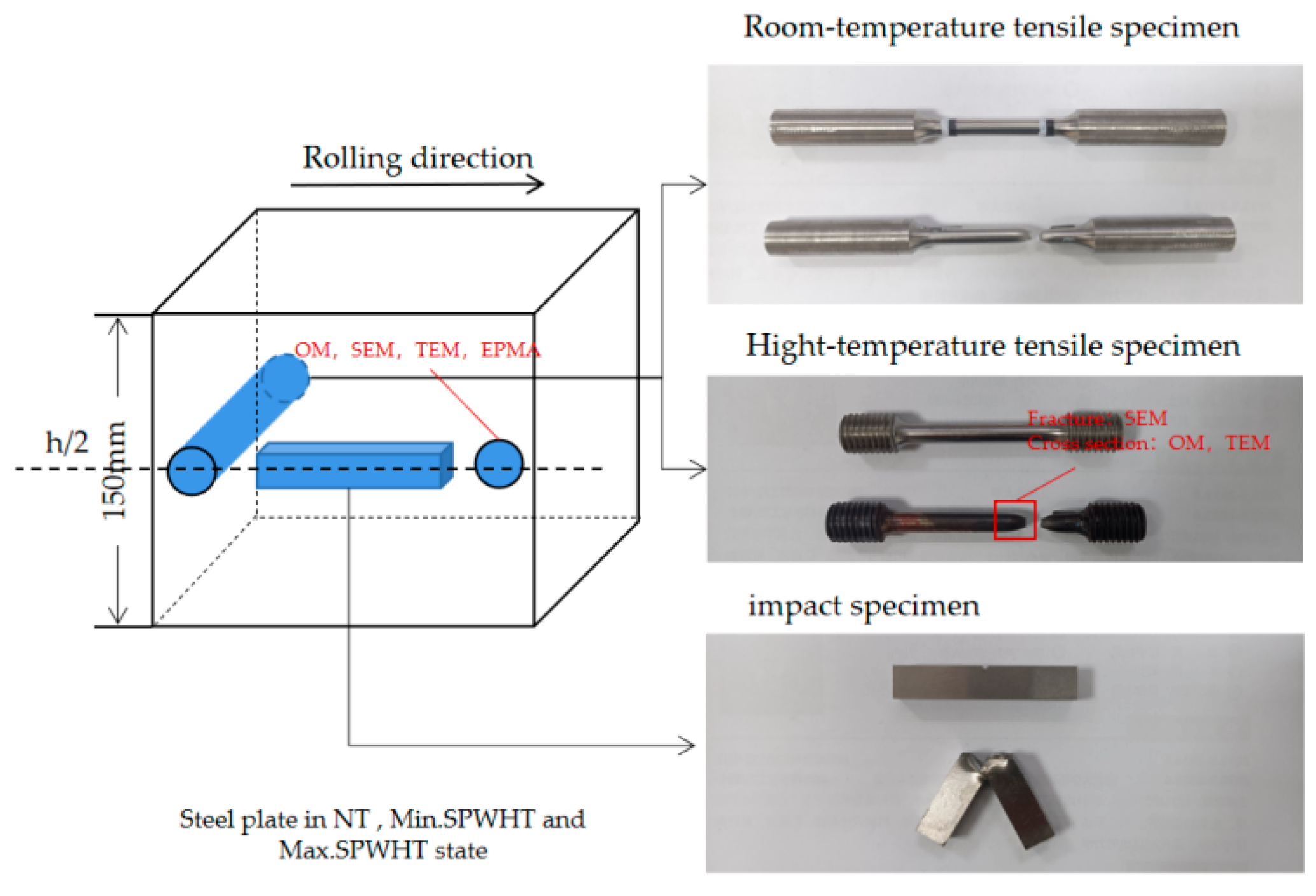
Figure 2.
(a) Hardness, (b) −30 °C impact energy, (c) yield strength, and (d) tensile strength of 2.25Cr1Mo0.25V steel before and after SPWHT.
Figure 2.
(a) Hardness, (b) −30 °C impact energy, (c) yield strength, and (d) tensile strength of 2.25Cr1Mo0.25V steel before and after SPWHT.
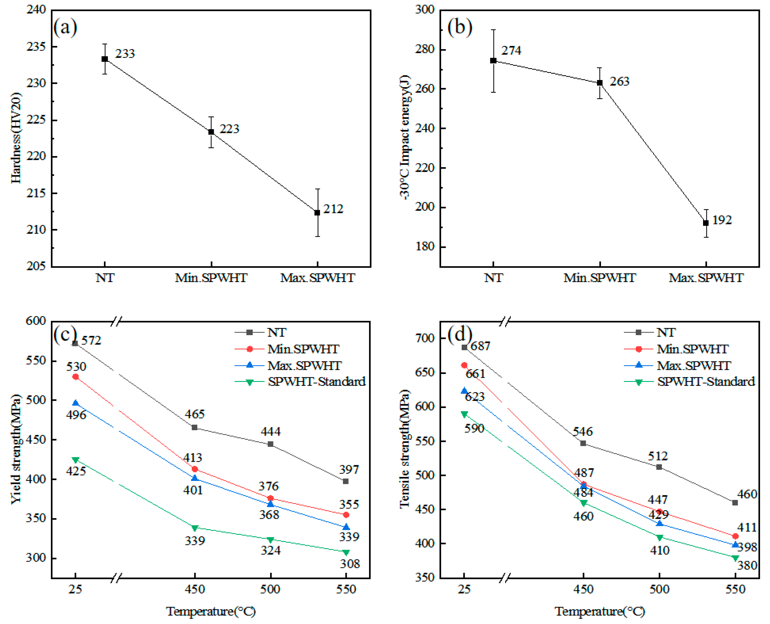
Figure 3.
(a) Metallographic picture, (b) low-magnification picture, and (c) high-magnification picture of the microstructure of the 2.25Cr1Mo0.25V steel in the NT state (as-receive state).
Figure 3.
(a) Metallographic picture, (b) low-magnification picture, and (c) high-magnification picture of the microstructure of the 2.25Cr1Mo0.25V steel in the NT state (as-receive state).
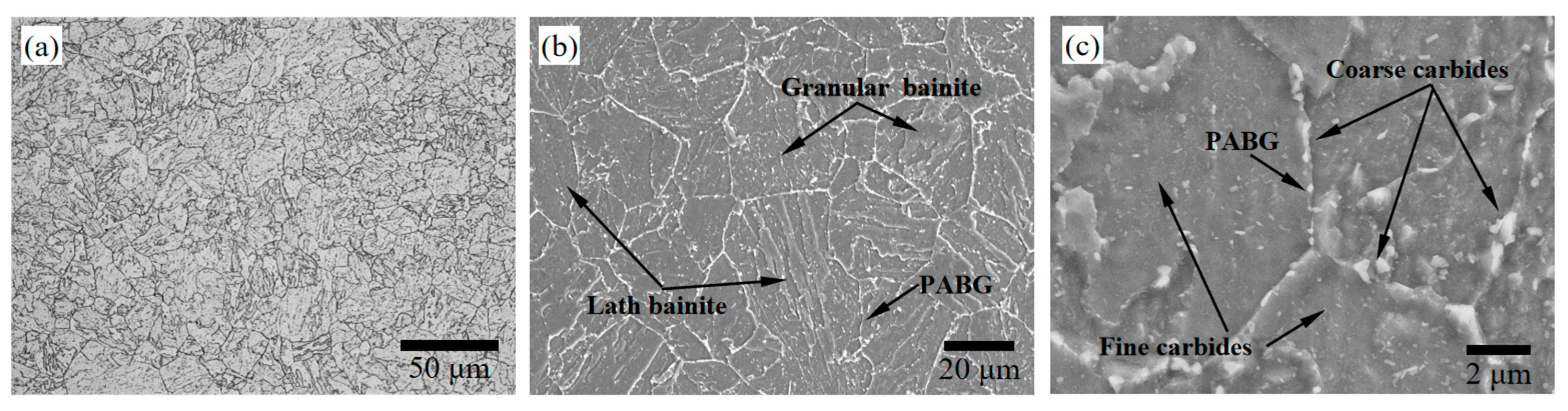
Figure 4.
(a) Metallographic picture, (b) low-magnification picture, and (c) high-magnification picture of the microstructure of the 2.25Cr1Mo0.25V steel in Min.SPWHT; (d) Metallographic picture, (e) low-magnification picture, and (f) high-magnification picture of the microstructure of the 2.25Cr1Mo0.25V steel in Max.SPWHT.
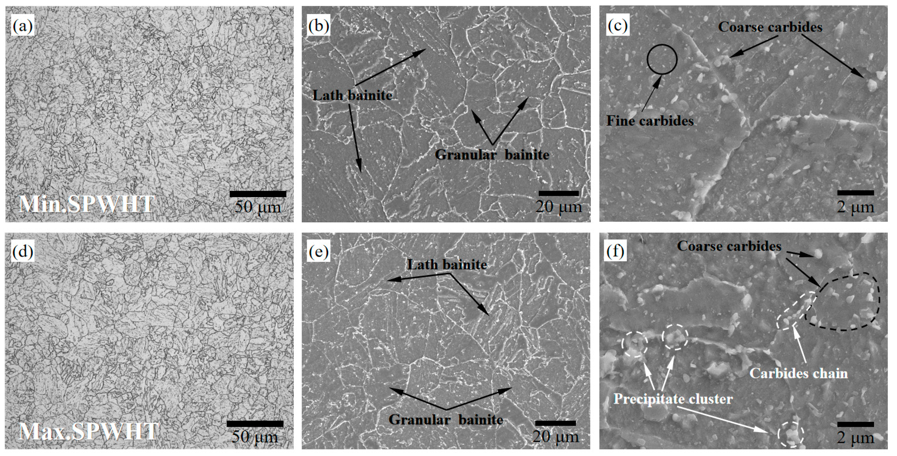
Figure 5.
TEM images of the microstructure in the precipitates of the 2.25Cr1Mo0.25V steel in the (a–c) NT state and (d–f) Max.SPWHT state.
Figure 5.
TEM images of the microstructure in the precipitates of the 2.25Cr1Mo0.25V steel in the (a–c) NT state and (d–f) Max.SPWHT state.
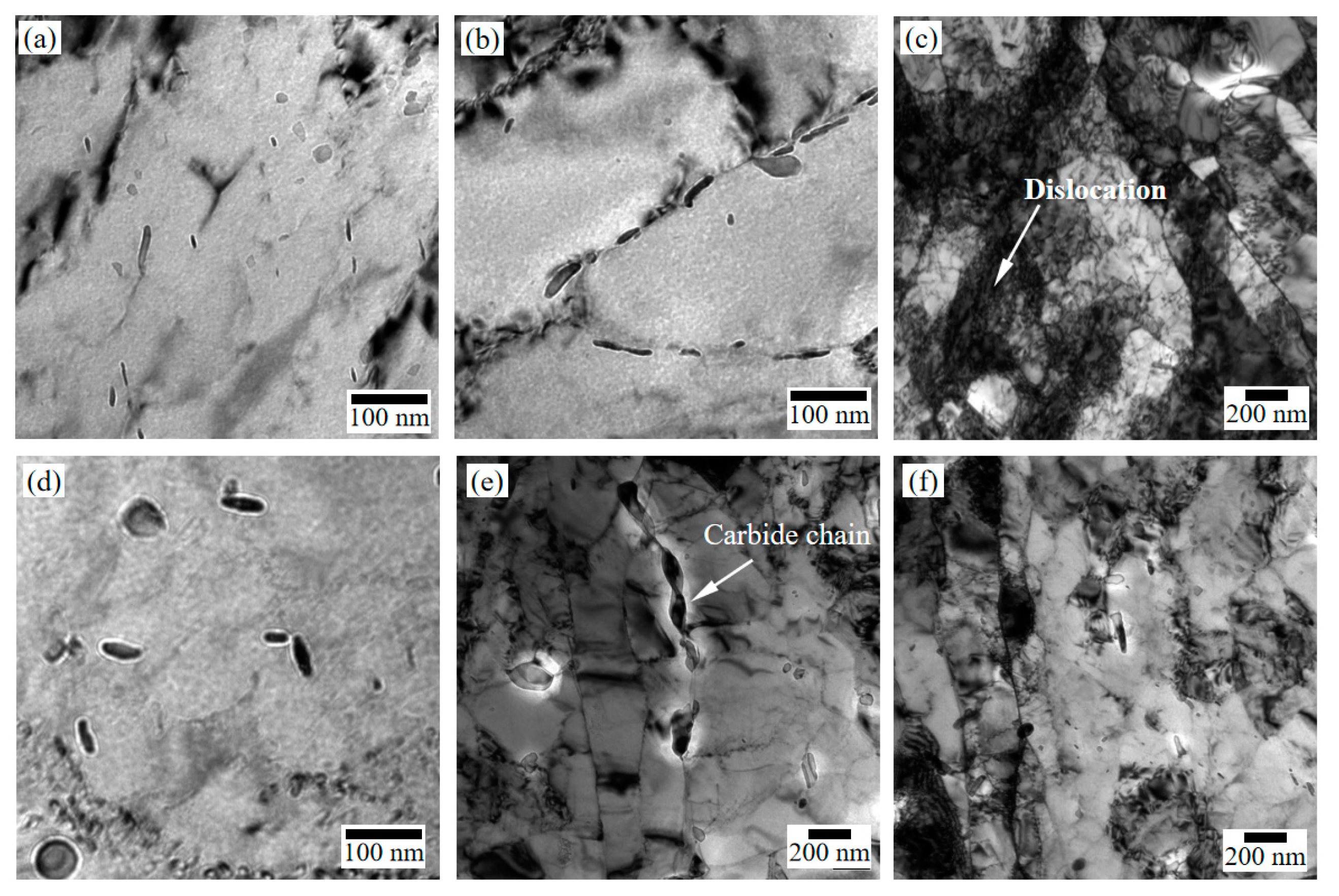
Figure 6.
Average size change of carbide in the 2.25Cr1Mo0.25V steel after Max.SPWHT.

Figure 7.
Distribution of C, Cr, Mo, and V in the 2.25Cr1Mo0.25V steel in the (a1–a5) NT, (b1–b5) Min.SPWHT, and (c1–c5) Max.SPWHT states by EPMA.
Figure 7.
Distribution of C, Cr, Mo, and V in the 2.25Cr1Mo0.25V steel in the (a1–a5) NT, (b1–b5) Min.SPWHT, and (c1–c5) Max.SPWHT states by EPMA.
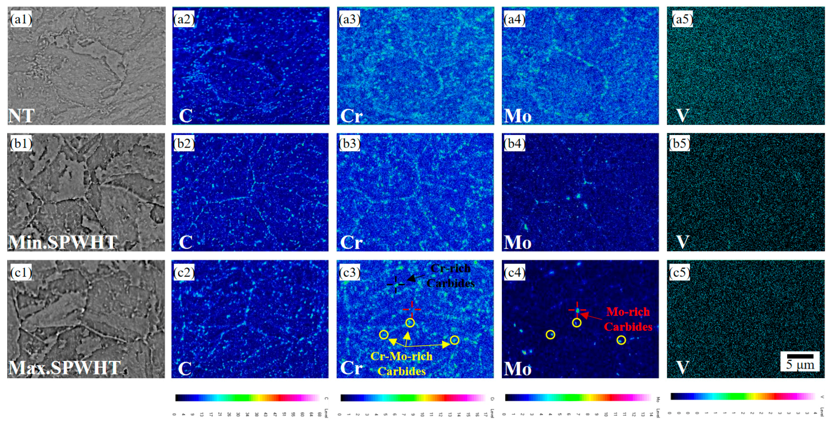
Figure 8.
EDS spectra of spectrum 1 and 8 marked in Figure 9.
Figure 8.
EDS spectra of spectrum 1 and 8 marked in Figure 9.

Figure 9.
The position of the measured point in the (a) NT specimen, (b) Min.SPWHT specimen, and (c) Max.SPWHT specimen in the EDS test.
Figure 9.
The position of the measured point in the (a) NT specimen, (b) Min.SPWHT specimen, and (c) Max.SPWHT specimen in the EDS test.
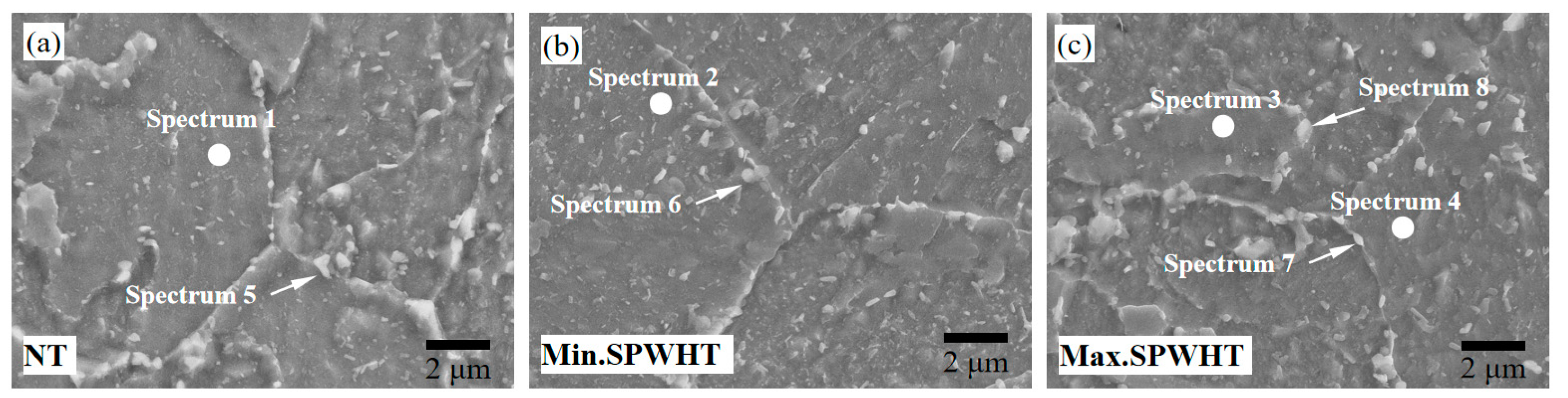
Figure 10.
(a) The picture of the 550 °C tensile specimen subjected to Max.SPWHT; (b) the reduction rate of the area of the specimen after the high-temperature tension test.
Figure 10.
(a) The picture of the 550 °C tensile specimen subjected to Max.SPWHT; (b) the reduction rate of the area of the specimen after the high-temperature tension test.
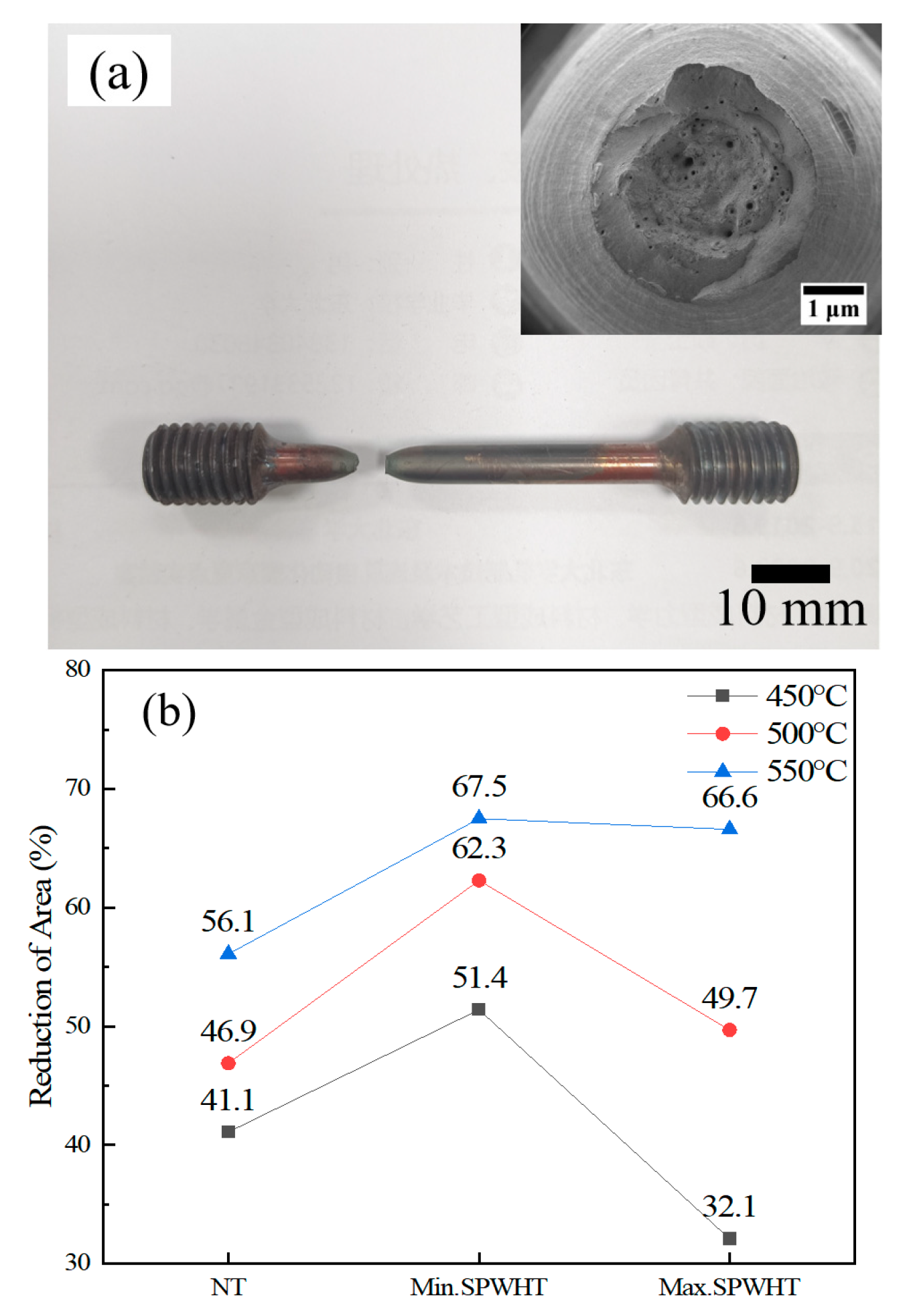
Figure 11.
The micro-morphology of the fracture of the tensile specimens of the 2.25Cr1Mo0.25V steel in the (a–c) NT, (d–f) Min.SPWHT, and (g–i) Max.SPWHT states at 450–550 °C.
Figure 11.
The micro-morphology of the fracture of the tensile specimens of the 2.25Cr1Mo0.25V steel in the (a–c) NT, (d–f) Min.SPWHT, and (g–i) Max.SPWHT states at 450–550 °C.
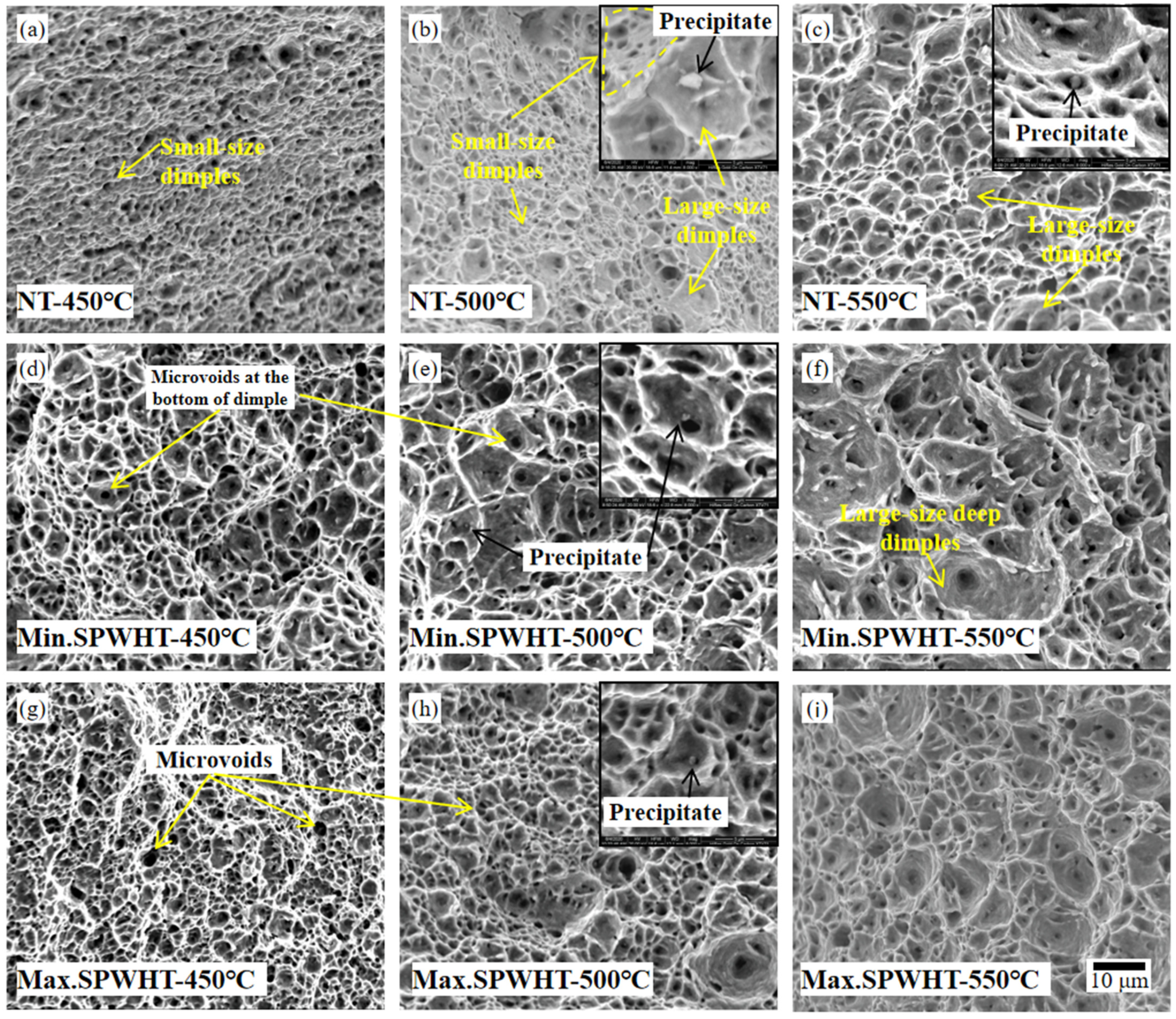
Figure 12.
SEM images of the necking area of the (a) 450 °C, (b) 500 °C, and (c) 550 °C tensile samples. All samples were subjected to Max.SPWHT.
Figure 12.
SEM images of the necking area of the (a) 450 °C, (b) 500 °C, and (c) 550 °C tensile samples. All samples were subjected to Max.SPWHT.
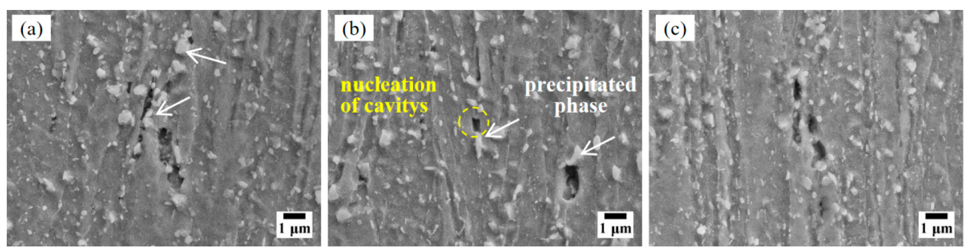
Figure 13.
TEM images showing (a) many carbides forming on the dislocation lines, (b) the large-sized carbides at the grain boundary in the necking area of the 450 °C tensile samples, (c,d) carbides in the necking area of the 500 °C tensile samples, and (e,f) carbides in necking area of the 550 °C tensile samples. All samples were subjected to Max.SPWHT.

Table 1.
Chemical composition of 2.25Cr1Mo0.25V steel in wt.%.
| Element | C | Si | Mn | Cr | Ni | Mo | B | V | Ti | Fe |
|---|---|---|---|---|---|---|---|---|---|---|
| value | 0.14 | 0.10 | 0.50 | 2.31 | 0.15 | 1.00 | 0.002 | 0.25 | 0.02 | bal |
Table 2.
Mechanical properties of 2.25Cr1Mo0.25V steel.
| Hardness/HV20 | −30 °C Impact Energy/J | ReL/MPa | Rm/MPa | ||
|---|---|---|---|---|---|
| NT | 231, 235, 234 | 257, 288, 278 | 25 °C | 572 | 687 |
| 450 °C | 465 | 546 | |||
| 500 °C | 444 | 512 | |||
| 550 °C | 397 | 460 | |||
| Standard | ≤235 HV | ≥54 J | 25 °C | 425–620 | 590–760 |
| 450–500 °C | ≥350 | - |
Publisher’s Note: MDPI stays neutral with regard to jurisdictional claims in published maps and institutional affiliations. |
© 2022 by the authors. Licensee MDPI, Basel, Switzerland. This article is an open access article distributed under the terms and conditions of the Creative Commons Attribution (CC BY) license (https://creativecommons.org/licenses/by/4.0/).
Share and Cite
MDPI and ACS Style
Li, Y.; Cui, Y.; Zhang, J.; Song, M.; Xu, C. Effects of Simulated PWHT on the Microstructure and Mechanical Properties of 2.25Cr1Mo0.25V Steel for a Hydrogenation Reactor. Metals 2022, 12, 1978. https://doi.org/10.3390/met12111978
AMA Style
Li Y, Cui Y, Zhang J, Song M, Xu C. Effects of Simulated PWHT on the Microstructure and Mechanical Properties of 2.25Cr1Mo0.25V Steel for a Hydrogenation Reactor. Metals. 2022; 12(11):1978. https://doi.org/10.3390/met12111978
Chicago/Turabian StyleLi, Yanmei, Yonghao Cui, Jimou Zhang, Minghui Song, and Chen Xu. 2022. "Effects of Simulated PWHT on the Microstructure and Mechanical Properties of 2.25Cr1Mo0.25V Steel for a Hydrogenation Reactor" Metals 12, no. 11: 1978. https://doi.org/10.3390/met12111978
Note that from the first issue of 2016, this journal uses article numbers instead of page numbers. See further details here.