Article

Comprehensive Weldability Criterion for Magnetic Pulse Welding of Dissimilar Materials

1
Department of Materials Engineering, Faculty of Engineering Technology, KU Leuven, Campus De Nayer, 2860 Sint-Katelijne Waver, Belgium
2
Indian Institute of Technology Hyderabad, Sangareddy 502284, Telangana, India
3
Defence Research and Development Laboratory, Kanchanbagh, Hyderabad 500058, Telangana, India
*
Authors to whom correspondence should be addressed.
Metals 2022, 12(11), 1791; https://doi.org/10.3390/met12111791
Submission received: 29 September 2022 / Revised: 18 October 2022 / Accepted: 21 October 2022 / Published: 23 October 2022
(This article belongs to the Special Issue Advances in Impulse Manufacturing)

Abstract

:
Despite its exceptional ability to join dissimilar materials and environmental friendliness, several challenges must be addressed in magnetic pulse welding (MPW). The conventional weldability criterion (i.e., minimum impact velocity) is analytically calculated as a function of material properties without considering the geometry of electromagnetic coil, electrical and physical parameters, making the minimum impact velocity a necessary but not sufficient condition for a sound MPW joint. A new weldability criterion, namely effective impact velocity, is proposed, which overcomes the conventional weldability criterion’s limitations. The effective impact velocity can be inversely modelled to identify shop-floor relevant process parameters and it eliminates the need to fabricate several coils in the process and product proving stages. The proposed approach is demonstrated by a case study on tubular welding of Aluminium and SS304. The weld’s soundness produced with computed process parameters was corroborated by experimental observations on lap shear tests, hardness measurements, optical and scanning electron microscopy, and surface energy dispersive spectroscopy mapping. This investigation is expected to pave the way for developing the process window for MPW of several material combinations, with high cost and time savings.

1. Introduction

Developing optimal lightweight structures by joining dissimilar materials has increased remarkably in many industries, such as automotive, aerospace, tooling, power generation, and marine applications. The joining of dissimilar materials by fusion welding causes unfavorable microstructures [1]. Chemical interaction between dissimilar materials leads to metallurgical incompatibility and brittle intermetallic compound (IMC) formation. Other issues include differences in the thermal and physical properties (thermal conductivity and coefficient of thermal expansion), the type of suitable heat treatment of the dissimilar joint, and galvanic corrosion [1]. When joining dissimilar materials, the product and joining process design must overcome the above-stated challenges [2]. Solid-state welding techniques facilitate joints’ formation at low temperatures and often very quickly, usually within microseconds [3]. Examples include explosive welding (EXW) [4], magnetic pulse welding (MPW) [1], vaporizing foil actuator welding [5], cold welding, and diffusion welding. These processes involve reduced formation of harmful and brittle IMCs, thereby keeping the material properties intact. Among the solid-state processes, MPW is one of the most environmentally friendly methods for joining dissimilar materials, wherein electromagnetic forces impact one metal onto another to form a solid-state cold weld. Ampere’s law governs the process. The force ( F ) experienced by two parallel current-carrying conductors with the distance of separation ( d ) is given as [6]:
F = μ 0 2 π d   I 1 I 2
where I 1 and I 2 are the currents flowing in the conductors and μ 0 is the permeability of free space. This force is known as the Lorentz force and is repulsive when the currents flow in opposite directions. Figure 1 shows the setup of a tubular MPW configuration, including the outer flyer tube, the coil, and the field shaper, which drives the flyer tube to cause a high-speed impact with the inner target tube. The flyer and target tubes collide at velocities from 250 to 500 m/s [7], forming a solid-state joint because of severe plastic deformation.
MPW might offer a joint strength around that of the weaker material without any emission, making the process environmentally friendly. Despite its many advantages, the spread of MPW is limited because of the higher initial investment in electromagnetic coils. Several coils are tested before obtaining a shop-floor applicable coil design. Numerical modeling allows the materials and geometry to be changed without additional expenditure and can be used to determine a process’s feasibility with high precision. However, this depends upon how critically numerical results are analyzed and corroborated with experimental results. The literature on combined modeling and experimental work in MPW of dissimilar metals is presented in Table 1. Although considerable effort has been put forward to develop rigorous numerical models combined with experimental work that can accurately capture the MPW process, there is a lack of work that concentrates on developing weldability criteria.
The investigations listed in Table 1 consider minimum impact velocity, impact angle, and interface morphology as indicators of the success of the joint. Recently, an analytical model was developed to identify the parameter combinations leading to creating a wavy pattern [39]. In their review, Ribeiro et al. [40] provided an integrated description of the weldability limits and criterion and its associated equations with the variables and parameters. The minimum impact velocity, also known as the threshold impact velocity criterion, is one-sided and can be considered necessary but not sufficient. The minimum impact velocity is calculated using material properties (as described in a later part). It does not consider the actual scenario, which includes the quality of mating surfaces, the geometry of an electromagnetic coil and electrical and physical parameters, such as air gap and tube/plate thickness. Therefore, the calculated minimum impact velocity might not always ensure a sound weld. The minimum impact velocity criterion does not prescribe any target velocity or corresponding process parameters. The investigation in this article proposes an approach to computationally identify target process parameters used on the shop floor after corroboration with a minimal number of experiments.
This study’s broader objective is to present an integrated numerical and experimental framework that could overcome technical and economic limitations in product and process development through MPW. This investigation proposes a comprehensive weldability criterion—effective impact velocity—that is sufficient to overcome surface imperfections and incorporates material properties and process parameters in the numerical algorithm used to compute the impact velocity. The investigation also demonstrates inverse modeling of effective impact velocity to obtain coil geometry and operating parameters required for shop-floor applications without fabricating several coils. The following section presents the FEM used in this investigation along with the details of the experimental techniques. Weldability criteria and methods for the selection of process parameters are presented after that. The efficacy of the proposed approach is then evaluated through the proximity of numerical and experimental observations on the interfacial mapping of hardness, plastic strain, and elemental distribution, following the analysis and discussion of the results obtained in this investigation.

2. Numerical Modeling and Experimental Method

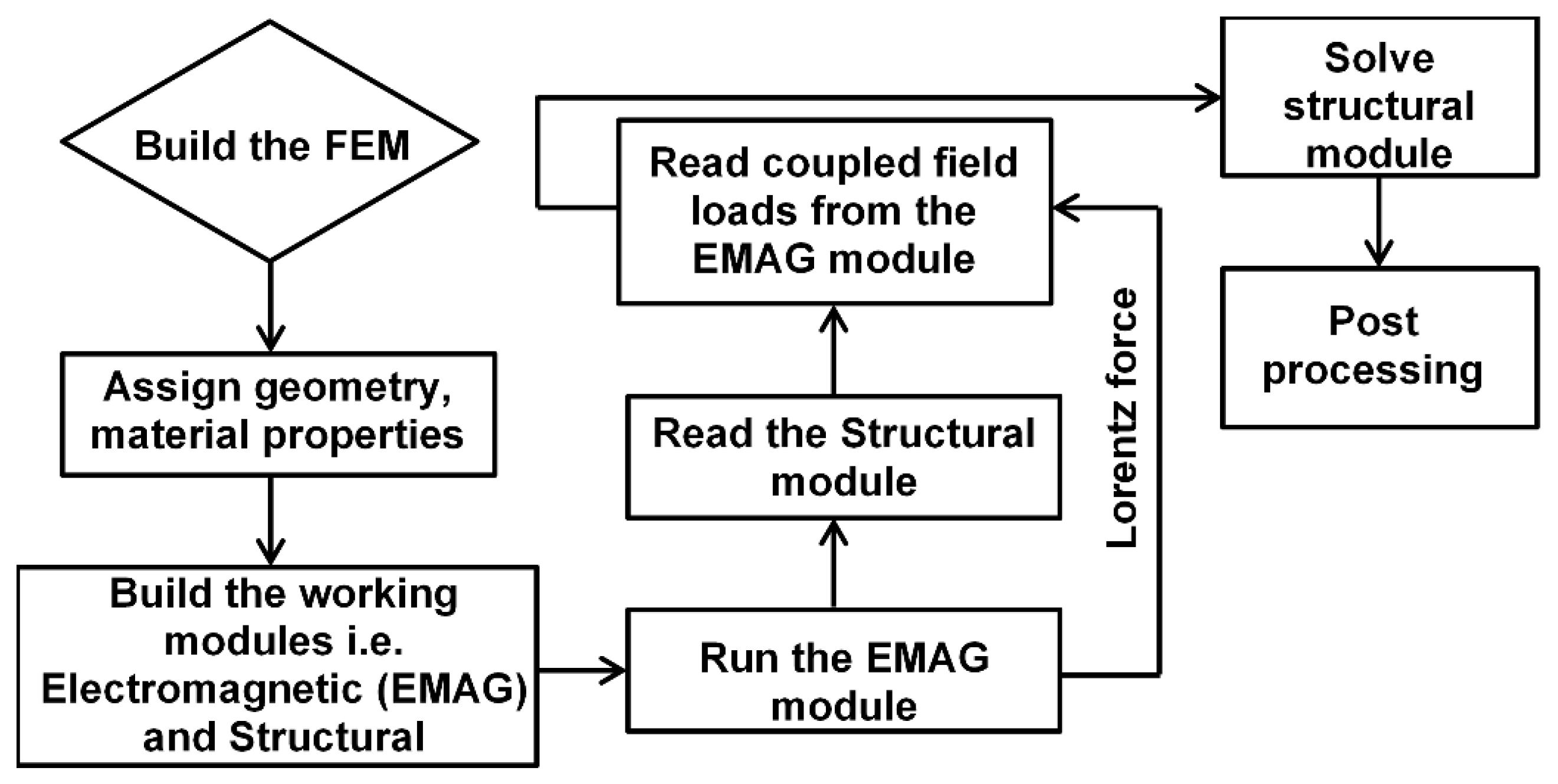
2.1. Finite Element Model

MPW involves a complex combination of electromagnetism and structural mechanics. Maxwell’s equations govern MPW. Substitution of the constitutive equations into Maxwell’s equations leads to Equation (2) for the tube region:
× ( 1 μ   × A ) = Υ A t
where magnetic permeability (H/m) is μ, ϒ is medium conductivity (S/m), ϒ ( A / ∂t) is the current density (A/m2) and A is the magnetic vector potential. The electromagnetic module calculates the transient magnetic forces at each time step. Maxwell’s relation gives the magnetic force f as follows:
f = J × B = 1 μ ( × B ) × B
where J is the current density in the electromagnetic coil (A/m2) and B is the magnetic flux density (T). The electromagnetic module outputs Lorentz force, an input for the structural module. The current passing through the coil is the body load for the electromagnetic module.
I = U { C L e x p ( β t ) sin ( ω t ) }
where charging voltage (kV) is U, capacitance (μF) is C, inductance (nH) is L, damping exponent is β , and angular frequency (rad/s, 1 rad/s = 0.1592 Hz) is shown by ω.
The material conduct of the flyer and target tubes is described by the Cowper–Symonds constitutive model [41]:
σ = σ y [ 1 + ( ε ˙ P ) m ]
where quasi-static flow stress is σ y , plastic strain rate (s−1) is ε ˙ , and m and P are constants that depend on the material.
A typical MPW simulation consists of an electromagnetic module (for the coil) and a structural module (for tubes). A nonlinear solver is used in the electromagnetic environment to calculate the transient magnetic forces. The forces are provided to the structural module to obtain deformation. The structural module considers the inertial effects due to time-dependent stress. Figure 2 presents a flowchart of the sequentially coupled electromagnetic–structural analysis. The FEM model was developed assuming that cracking, the heat generated by friction, deformation, and joule heating is negligible. Thus, temperature-independent elastoplastic properties are used. The effect of resistance from air compression between the tubes is neglected. An Augmented Lagrangian contact pressure method and a time-dependent multifrontal massively parallel sparse direct solver (MUMPS) were employed. A field shaper has not been employed in this work. As explained next, a 2D axisymmetric problem using FEM was solved in COMSOL for the candidate material pair (Al–SS304). In this study, the geometry of the flyer was not changed during the simulations. Several process parameters that directly or indirectly influence the impact velocity, including input voltage, coil turns, coil length, coil cross-sectional area, capacitance, air gap, and current frequency, were varied for the simulations. Table 2 lists all the process parameters along with the range of variation. The operational details of the FEM are presented in Table 3. For additional details on the FEM employed in this study, the authors’ previous work can be referred to [42,43].

2.2. Experimental Method

A tubular bi-metallic joint configuration, as shown in Figure 3, was fabricated. The material composition of the constituent base materials and electromagnetic coil are given in Table 4. The feasible process parameters were obtained by a selection process described in the next section.
The welded sample was tested using the lap-shear test, micro-hardness measurements, and metallographic examination using an Olympus STM6-LM optical microscope (OM) (OLYMPUS, Tokyo, Japan) and Carl Zeiss AG-Supra 40 field electron scanning electron microscope (FESEM) (ZEISS, Oberkochen, Germany). Elemental distribution mapping was obtained through energy dispersive spectroscopy (EDS) analysis of the Al and SS304 members’ interface. Surface mapping of the interface was also carried out to check for the diffusion of one metal into the other at the welded interface.

3. Algorithmic Approach for Shop-Floor-Applicable Process Parameters

3.1. Development of Weldability Criteria: Threshold Velocity vs. Effective Velocity

Impact velocity is an essential criterion for successful bonding. The impact velocity relations available for EXW are equally applicable for MPW as both processes go through the same interface phenomenon [1]. The critical impact pressure (Pc) essential for a successful joint is given as follows:
P c = 1 2 Z e q V T cos Φ
where Zeq represents the equivalent acoustic impedance of the colliding sheets/tubes,   Φ is the angle for the jet formation, and VT is the minimum (threshold) impact velocity essential for bond formation. The Zeq is computed by individual acoustic impedances of two members as follows:
Z e q = 2 1 Z 1 + 1 Z 2
where Z 1 = ρ 1 S 1 is the flyer sheet/tube acoustic impedance, Z 2 = ρ 2 S 2 is the target sheet/tube acoustic impedance, S 1 and S 2 are the speeds of sound in the flyer and target sheet/tube materials, respectively, and ρ 1   and   ρ 2 are the material densities of the two sheets/tubes. For a successful weld, the threshold value of pressure must exceed five times the Hugoniot elastic limit (HEL), which is given as:
H E L = 1 2 ( K G + 4 3 ) Y 0
where K is the bulk modulus, G is the shear modulus, and Y 0 is the tensile yield stress.
The threshold value of impact velocity was calculated for the candidate material pair (Al–SS304) using the corresponding material properties presented in Table 2. The higher impact velocity among the two candidate materials was considered the threshold impact velocity, which in the present case was 161.03 m/s for SS304.
The threshold impact velocity (VT) is a necessary but not sufficient condition for bond formation. As the interface of the weld is subjected to severe plastic deformation, an increase in impact velocity improves the likelihood of bonding. Moreover, achieving a theoretical threshold impact velocity might not remove the impurities and the oxide layer from the surface, leading to joint failure. On the other hand, excessive impact velocity damages the part itself. Even if the impact velocity remains under the maximum achievable impact velocity without damage (VD), the possibility of IMC formation is increased at higher impact velocities. Thus, the effective impact velocity (VI) (i.e., impact velocity expected during the actual experiment) should be higher than the threshold impact velocity but remain lower than VD. A typical jet behavior establishes a steady-state wave pattern at intermediate velocities, and the maximum bond strength is obtained [42]. Because of these limitations, the effective impact velocity (VI) is proposed as a weldability criterion. The desired (i.e., effective) impact velocity is considered to be in the vicinity of the average of the threshold impact velocity (VT) and maximum achievable impact velocity without damage (VD) as follows:
V I V T + V D 2
The maximum achievable impact velocity without damage (VD) can be estimated by FEM simulation, which is discussed later. However, FEM simulation overpredicts the impact velocity as the effect of resistance from air compression between the tubes is neglected [39]. To compensate for this, a velocity correction factor (ε) is introduced, such that
V D = V D S ε
where VDS is simulated maximum achievable impact velocity without damage. Using Equation (10) in Equation (9) results in the following:
V I V T + V D S ε   2
The effective velocity can be used to obtain process parameters through inverse modeling. However, as explained earlier, the velocity correction factor (ε) is also applied to the simulated effective impact velocity. Thus,
V I = V I S ε
where VIS is simulated effective impact velocity.
Applying Equation (12) in Equation (11) yields
V I S ε V T + V D S 2
The maximum achievable impact velocity without damage (VDS) is algorithmically obtained and used to calculate the effective impact velocity, which is then used to compute the parameters used on the shop floor.

3.2. Algorithm for Selection of Shop-Floor Applicable Parameters

Let V be the impact velocity influenced by m number of process parameters (X: xi; i = 1 to m), each operating in a range of [ximin, ximax]. The maximum achievable impact velocity by altering xi, while keeping others at mid-range is Vimax (i.e., V = Vimax; when xi = xiVmax). Let Vr: vk be a set of five maximum possible impact velocities in the neighborhood (within 1% difference) that can be reached without damage and obtained through simulation. Once the maximum achievable impact velocity without damage (VDS) is obtained, VIS (effective impact velocity) is calculated using Equation (13). The algorithm for calculating the effective impact velocity is shown in the flowchart in Figure 4. The process parameters corresponding to the effective impact velocity obtained by selective grid inverse modeling vis-à-vis the FEM are run several times by changing process parameters, such that every time the simulated impact velocity nears the effective impact velocity parameter, the matrix is updated. The process converges when no significant change in impact velocity is observed for a certain number of FEM runs.

4. Results and Discussion

4.1. Process Parameter Identification

The outcome of the process parameter selection exercise is shown in Figure 5. The one-parameter-at-a-time investigation indicates that for a candidate pair of a given geometry, higher voltage values, coil turns, coil cross-section area, capacitance and frequency, and a very narrow air gap can damage the flyer tube because of undesirably high impact velocity. The maximum achievable impact velocity without damage (VDs) and the simulated effective impact velocity (VIS) obtained using the algorithm shown in Figure 4 were 484 m/s and 338 m/s, respectively. The values of process parameters obtained from the inverse modeling (voltage = 16 kV, air gap = 1.5 mm, coil turns = 6, coil length = 27 mm, coil cross-section area = 9 mm2 (circular) and frequency = 50,000 rad/s) yielded a simulated impact velocity of 341 m/s, which is close to the calculated value. The welding sample was manufactured with the obtained process parameters and checked for different experimental attributes, as presented below.

4.2. Experimental Corroboration of FEM Observations

Experimental measurement of the impact velocity in MPW was largely conducted using optical methods, particularly with the use of a photonic Doppler velocimeter (PDV) [44,45]. In their previous work, the authors validated the FEM employed in this study by comparing the simulated impact velocity with the experimental impact velocity measured using PDV for various process conditions. Figure A1a,b (see Appendix A) depicts the comparison of the simulated and experimental impact velocities. In this study, the corroboration of the FEM observations was achieved through a comparison of the interface morphology and mechanical behavior, as presented next.
(a) Interface morphology
The pulse-welded Al-SS304 metal pair showed a wavy pattern at the impact zone, typical of MPW (Figure 6). The FEM also predicted a similar wavy morphology.
The flyer tube started moving as soon as the magnetic pressure generated by the electromagnetic coil exceeded the plasticization pressure, attaining a maximum velocity at the time of impact, and decreased as the process progressed. The impact velocity variation across the weld length resulted in different interface phenomena. An MPW tubular joint welded in the longitudinal direction can be divided into three zones, as shown in the cut weld section in Figure 7a.
The middle part of the mating members is where the joining occurs, and two non-welded zones occur on either side. The non-welded zones on the left and right in Figure 7a are called the run-in and run-out zones, respectively. The flyer tube and the target tube make an angle at the end of the run-out zone. A noticeable deformation occurs in the run-in zone. The target tube’s deformation declines gradually from the run-in to the run-out zone (Figure 7a). In the unbonded zones, the flyer tube rebounds and creates a gap between the two plates. The distinct bonded and unbonded zones are visible in the numerical results (Figure 7b). The similarity between the experimental and numerical results is an important outcome of the proposed approach.
(b) Mechanical behavior
Figure 8 shows the joints after the lap-shear test. For all specimens, fracture occurred outside the welded region and at weaker Al, proving that the weld was sound. This result validates the proposed approach, wherein process parameters obtained with numerical modeling passed the mechanical test.
An agreement between experimentally observed hardness mapping and numerically obtained plastic strain also justified the proposed approach. The interface layer showed increased hardness relative to the base material (BM) (Figure 9a). The transition zone had the highest hardness value of 302 HV, much higher than the average BM hardness values of 55 HV for Al and 210 HV for SS304. The micro-hardness promptly increased on both sides of the transition zone and tended to be constant beyond these regions. This behavior was attributable to severe plastic deformation at the interface, observed in the simulated strain distribution in Figure 9b. Higher stress and strain were generated in the bonded center zone compared to the unbonded run-in and run-out zones.
With increasing distance from the interface, the plastic deformation decreased, and with it, the micro-hardness values. The interface layer went through two possible phenomena—solid–solid bonding caused by plastic deformation and liquid–solid bonding due to a very thin layer formed by molten metal. In addition, the high-hardness IMC produced in the transition zone might result in higher hardness than that of the BMs [46]. The metallurgical investigation in the next section discusses the same phenomenon.

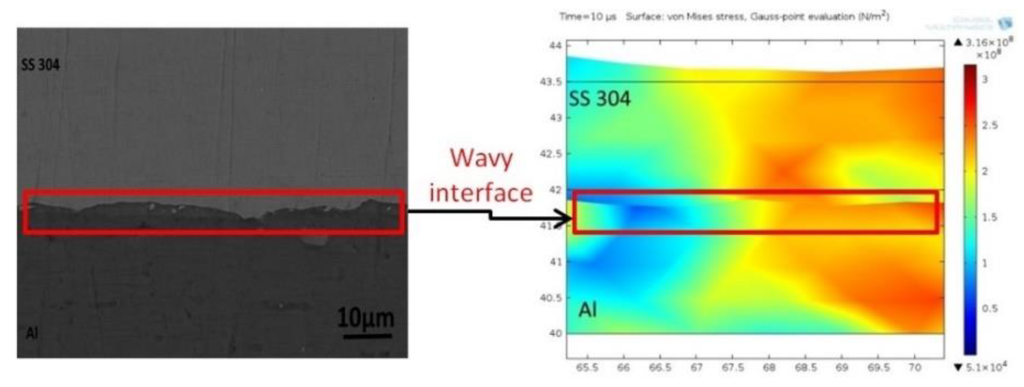
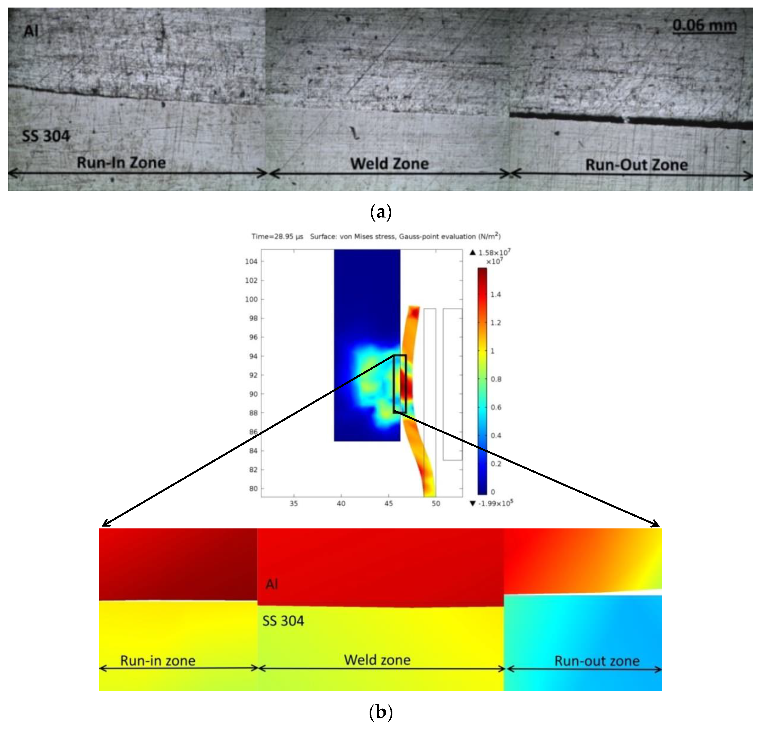
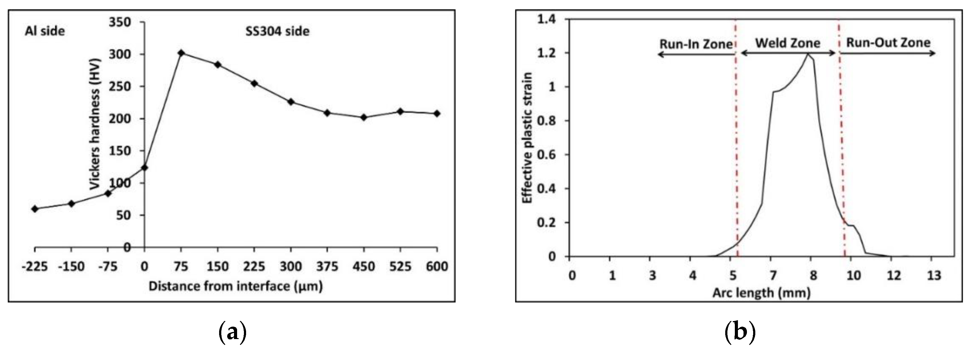
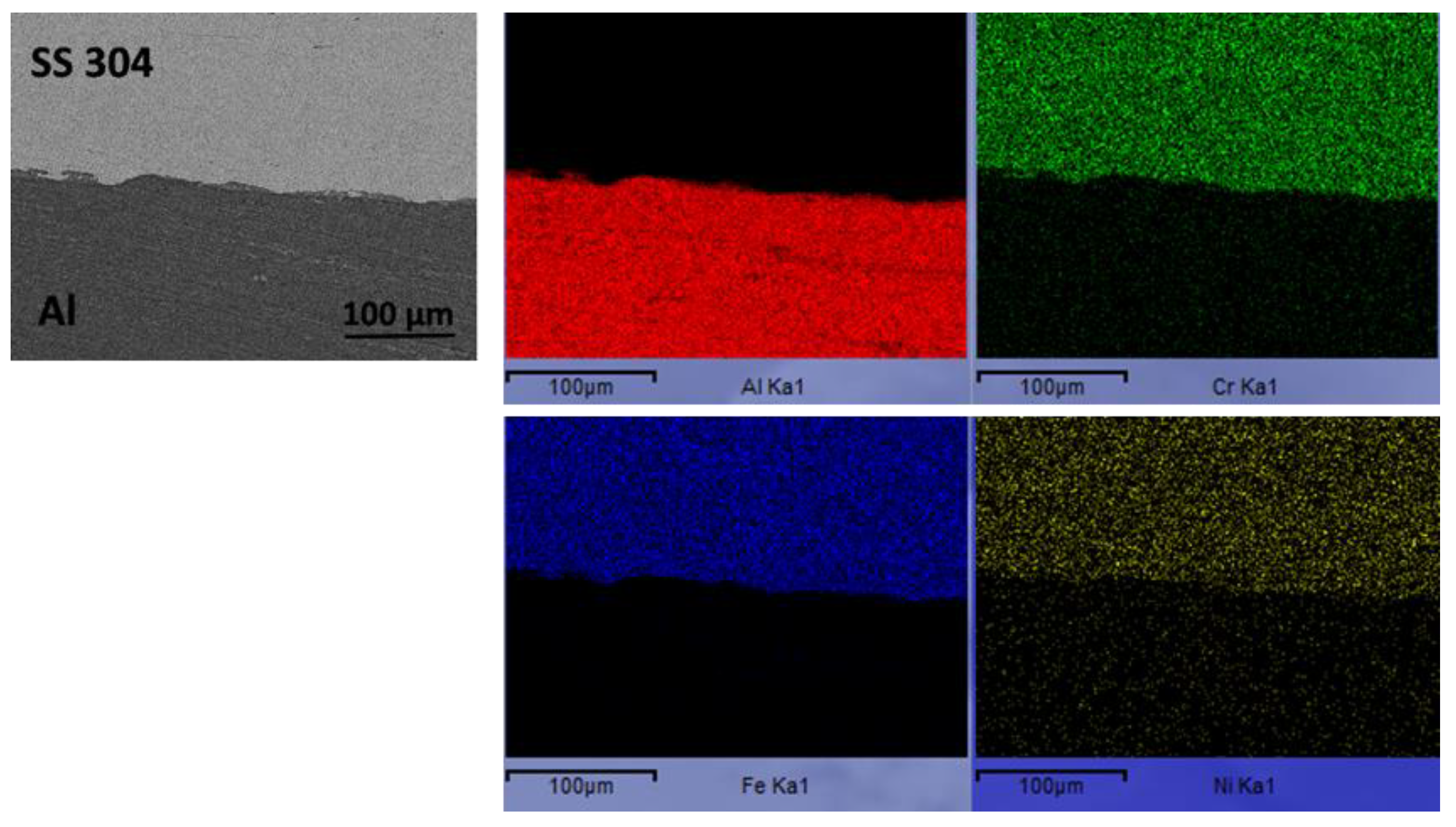
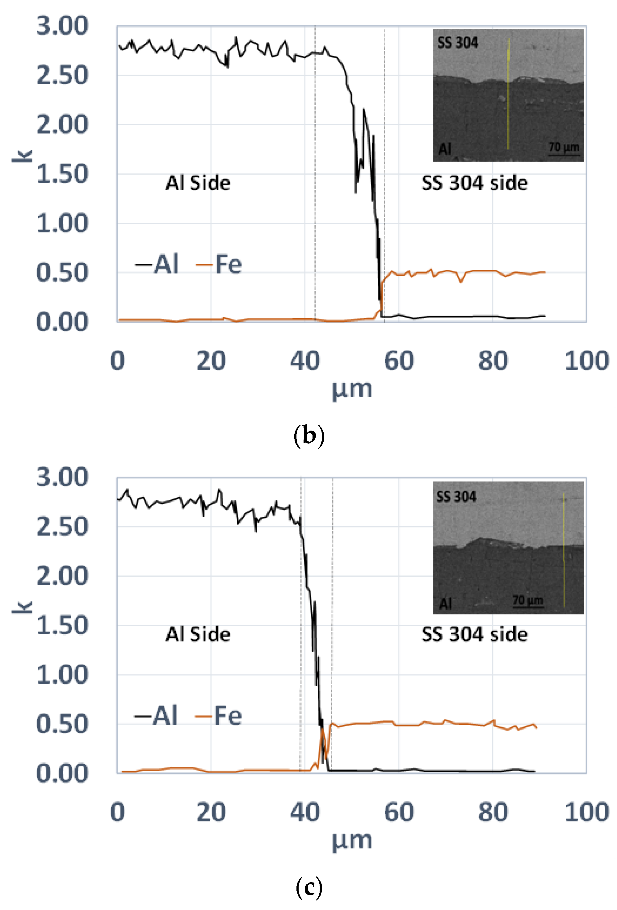
4.3. Metallurgical Investigation

The transfer of material between the flyer and target materials resulted in several phenomena. One of the reasons for the increase in hardness (Figure 9a) in the interface layer or transition zone is the material transfer between the mating members due to the high-speed impact. The intermetallic phase formation at the welding interface cannot be avoided during MPW, particularly in the case of dissimilar material joining. Raoelison et al. [47,48] investigated the effect of process conditions on the interface properties and weld features for Al/Al and Al/Cu MPW joints. They found that an Al/Cu pair led to the formation of an intermetallic phase, whereas an Al/Al pair had metal continuity at the bonded interface. The interface wave results were due to flow velocity discontinuities [49]. The discontinuities caused waves across the interface. The two fluids with different velocities resulted in instabilities at the interface, which led to mass flow from one material to the other. Thus, element diffusion is inevitable during MPW of dissimilar materials, as shown in the surface EDS map in Figure 10. The intermetallic zone formation could be a direct result of the atomic diffusion of one metal in the other.
Line EDS is used to determine the distribution of Al and SS304 across the weld interface for the bonded center zone. Line analysis was performed across the intermediate layer (IML) at the crest of a wave, the trough of a wave, and a flat interface, as shown in Figure 11a–c, respectively. The area between the dotted lines corresponds to the IML region. The composition of elements (primarily aluminum) changed sharply in the IML region. Beyond this region, the composition of elements was almost constant. The width of the IML changed along the length of the bonded zone. Figure 11a shows the distribution of elements in the line scan performed along the crest of a wave. The width of the IML, in this case, was approximately 9 μm. The IML zone width increased slightly, by around 12 μm, at the trough of the wavy interface (Figure 11b). The distribution of Al changed gradually by several micrometers and then sharply decreased to zero. Along the flat interface (Figure 11c), there was a considerable decrease in the width of the IML (by around 5 μm).
The chances of intermetallic phase formation increased with the increase in discharge energies. The maximum thickness of the intermetallic phase can increase to more than 25 µm at higher energies, which is detrimental to the weld quality and strength [50]. However, the maximum thickness observed with the parameters obtained from numerical modeling was around 10–12 μm, meaning the interface was free of any detrimental effects that indicate the proposed approach’s efficacy. The joint’s strength is also a result of interlocking between the two metal surfaces, as shown in Figure 12. A high-speed collision leads to the formation of a discontinuous interface that is mostly wavy, where the vortices of waves take part in mechanical interlocking as a joining mechanism. The interlocking is promoted by Al’s low strength and high ductility compared to SS304. This is like the combing action in dissimilar friction stir welding, where the low-strength alloy can penetrate the high-strength alloy and create mechanical interlocking. However, it is to be noted that the notion of interlocking due to the swirling kinematic flow in MPW may also be a defect site based on the nature of the swirl-affected zone. This is more evident in the case of MPW of dissimilar materials, where an intense swirling motion along the bi-metallic interface can lead to the formation of the intermediate phase, severely degrading the weld properties [47,48]. Thus, it is essential to have a proper set of input parameters that satisfy the weldability criterion and allow a significant reduction in the thickness of the intermediate phase.
The experimental results of the present study are consistent with the FEM model. The FEM and experimental results show similar weld interface characteristics, which gives confidence for predicting suitable process parameters for successful welding with few experimental runs. The proposed approach to identify the effective impact velocity and corresponding process parameters through inverse modeling is the first of its kind. It has immense potential to reduce process development costs using the MPW process. The developed model can be coupled with soft-computational tools such as artificial neural networks to enable machine learning-based evaluation of the MPW process.

5. Conclusions

This study investigates MPW and presents a new weldability criterion that overcomes existing limitations and offers an economical and timely process development approach. The major conclusions from the present investigation are:
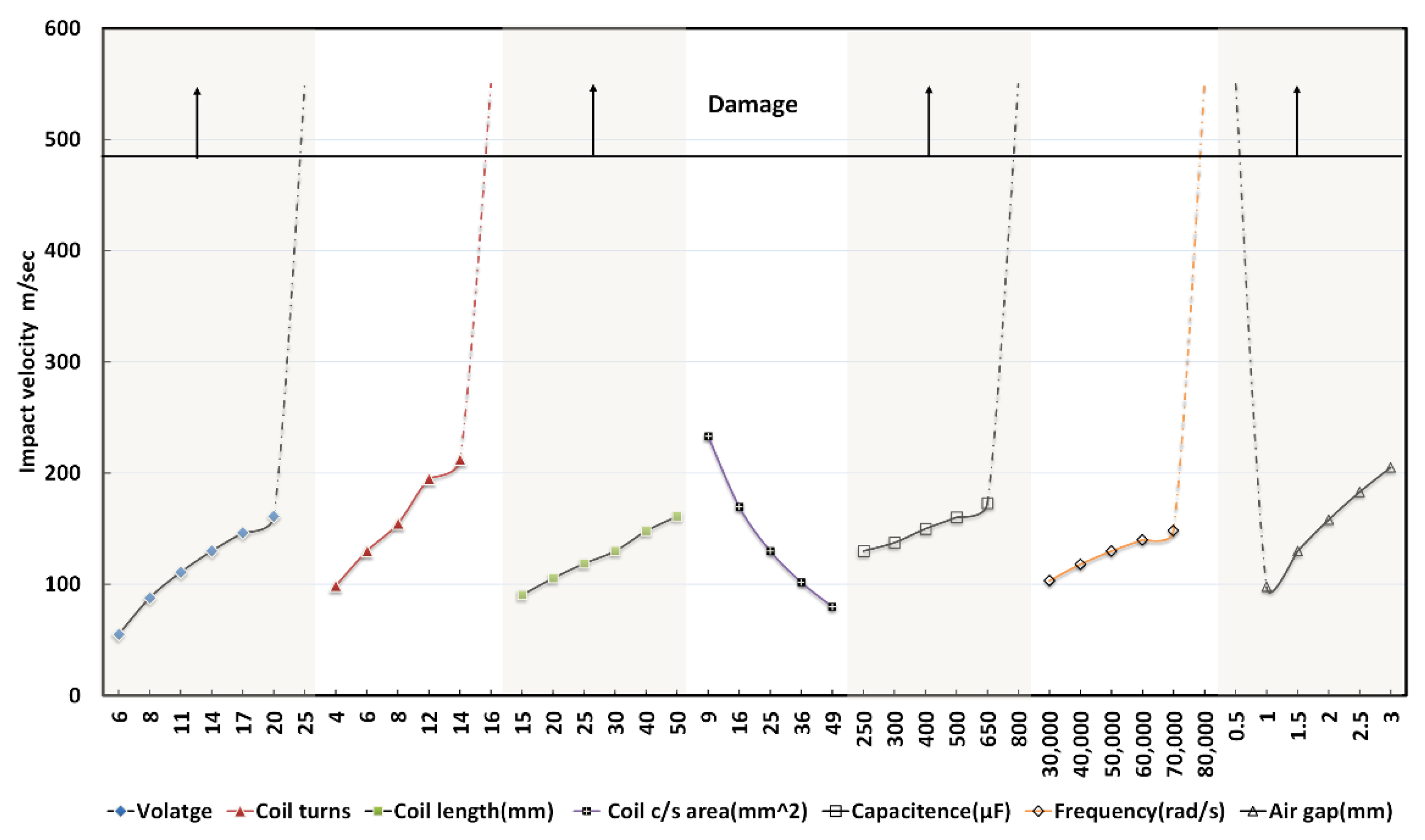
  • The conventional weldability criterion (threshold impact velocity) is necessary but insufficient, as it is calculated using material properties without considering the geometry of the electromagnetic coil, electrical and physical parameters, such as air gap and plate thickness, and surface imperfections. Such a criterion does not identify suitable process parameters for shop-floor applications.
  • A new criterion (effective impact velocity) is proposed, in which the effective impact velocity is the average of the threshold and maximum possible velocity without damage. The investigation offers a numeric algorithm to compute effective impact velocity, wherein the maximum possible velocity without damage is obtained through FEM simulation.
  • The proposed weldability criterion overcomes the existing limitations and can be numerically computed and inversely modeled, and thus can be used to prescribe shop-floor applicable process parameters.
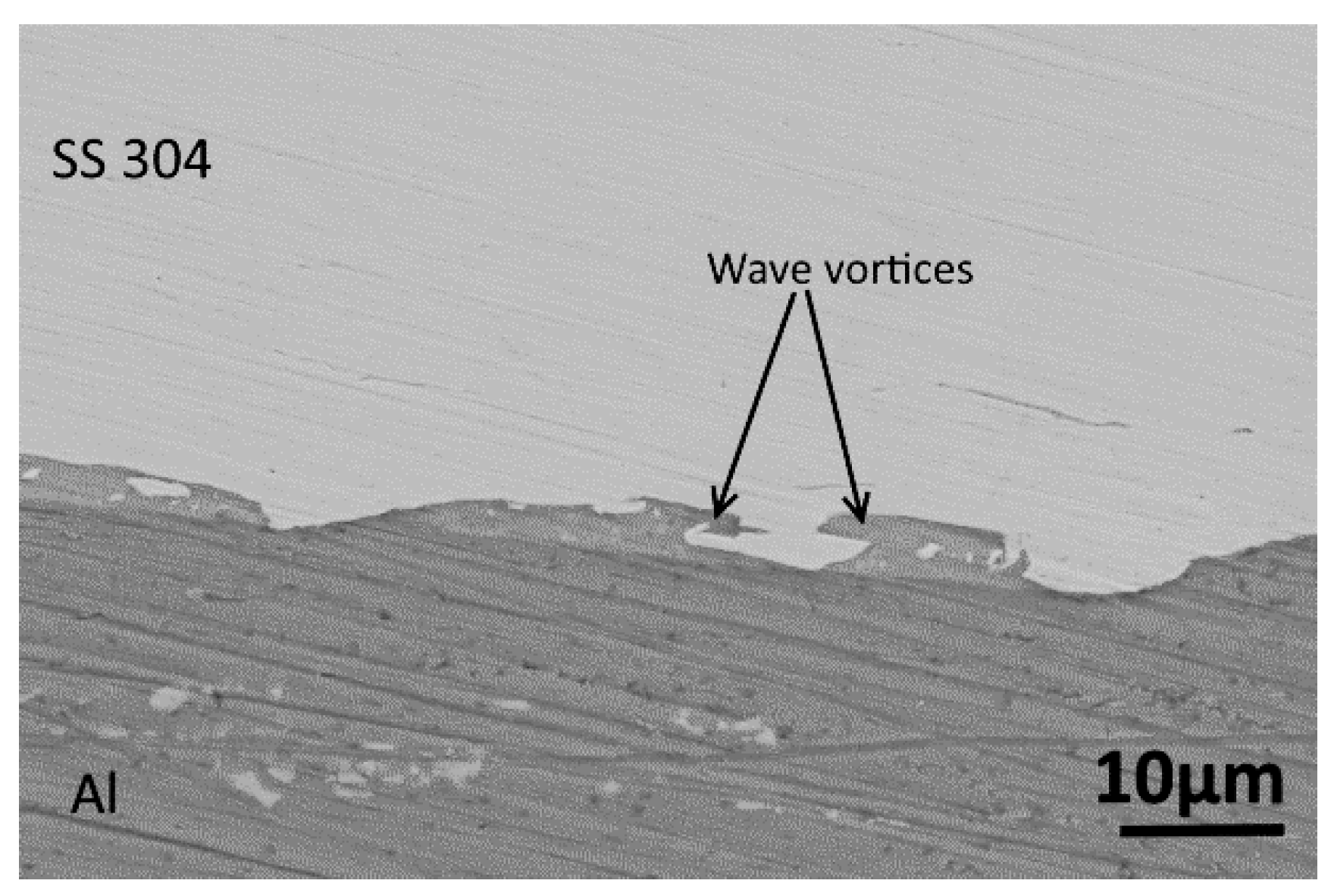
  • The weld samples obtained with numerically computed parameters were consistent with the experiments in terms of interface morphology, the intermediate layer’s width, and plastic strain distribution. The joints cleared lap shear tests, wherein fracture occurred outside the welded region—increased hardness in and around the interface zone corresponded with the predicted plastic strain in the FEM simulation. Surface energy dispersive spectroscopy also showed that the increased hardness was associated with element transfer at the interface during the severe plastic deformation at the time of impact.
  • The proposed approach is an experimentally corroborated and time-saving method that will encourage using finite element modeling to obtain shop-floor-applicable process parameters. Moreover, the cost will be reduced as use of the electromagnetic coil will be restricted to that of a few (essential for FEM validation), unlike conventional methods, wherein several coils are to be tested.

Author Contributions

Conceptualization, A.K. and A.S.; methodology, A.K. and A.S.; formal analysis, A.K. and A.S.; investigation, A.K. and P.M.; resources, A.S.; writing—original draft, A.K.; writing—review and editing, A.S.; visualization, A.K.; supervision, P.M. and A.S.; project administration, A.S. All authors have read and agreed to the published version of the manuscript.

Funding

A part of the investigation was carried out under the CARS project DRDL/24/08P/0509/41779.

Data Availability Statement

The raw/processed data generated during and/or analyzed during the current study are available from the corresponding author on reasonable request.

Conflicts of Interest

The authors declare no conflict of interest. The funders had no role in the design of the study; in the collection, analyses, or interpretation of data; in the writing of the manuscript, or in the decision to publish the results.

Appendix A

Figure A1a,b shows the comparison of experimental and simulated values of workpiece velocity computed by the FEM for dissimilar metal joining. It is seen that there was a close agreement between the simulated and experimental values within a range of ±10% variation. Figure A1a shows the comparison of simulated and experimentally measured impact velocities with variation in input energy and capacitance, and Figure A1b shows the comparison of simulated and experimentally measured impact velocities with variation in input voltage and air gap.
Figure A1. Comparison of experimental and simulated values of workpiece velocity for model validation: Case of compression joining of dissimilar materials (a) with variation of input energy and capacitance, data from [51], and (b) with variation of input voltage and air gap, data from [13,52].
Metals 12 01791 g0a1

References

  1. Kapil, A.; Sharma, A. Magnetic pulse welding: An efficient and environmentally friendly multi-material joining technique. J. Clean. Prod. 2015, 100, 35–58. [Google Scholar] [CrossRef]
  2. Martinsen, K.; Hu, S.J.; Carlson, B.E. Joining of dissimilar materials. CIRP ANN-Manuf. Techn. 2015, 64, 679–699. [Google Scholar] [CrossRef] [Green Version]
  3. Stern, A.; Aizenshtein, M. Bonding zone formation in magnetic pulse welds. Sci. Technol. Weld. Join. 2002, 7, 339–342. [Google Scholar] [CrossRef]
  4. Akbari Mousavi, S.A.A.; Al-Hassani, S.T.S. Numerical and experimental studies of the mechanism of the wavy interface formations in explosive/impact welding. J. Mech. Phys. Solids 2005, 53, 2501–2528. [Google Scholar] [CrossRef]
  5. Kapil, A.; Lee, T.; Vivek, A.; Bockbrader, J.; Abke, T.; Daehn, G. Benchmarking strength and fatigue properties of spot impact welds. J. Mater. Process. Technol. 2018, 255, 219–233. [Google Scholar] [CrossRef]
  6. Kore, S.D.; Date, P.P.; Kulkarni, S.V. Effect of process parameters on electromagnetic impact welding of aluminum sheets. Int. J. Impact Eng. 2007, 34, 1327–1341. [Google Scholar] [CrossRef]
  7. Aizawa, T.; Kashani, M.; Okagawa, K. Application of magnetic pulse welding for aluminum alloys and SPCC steel sheet joints. Weld. J. 2007, 86, 119–124. [Google Scholar]
  8. Hisashi, S.; Isao, S.; Sherif, R.; Hidekazu, M. Numerical study of joining process in magnetic pressure seam welding. Trans. JWRI 2009, 38, 63–68. [Google Scholar]
  9. Zhang, Y.; Daehn, G.; L’Eplattenier, P.; Babu, S. Experimental study and numerical simulation on magnetic pulse welding for pre-flanged AA6061-t6 and CU101 sheets. In Trends in Welding Research, Proceeding of the 8th International Conference, Pine Mountain, GA, USA, 1–6 June 2008; ASM International: Materials Park, OH, USA, 2009; pp. 715–720. [Google Scholar]
  10. Kore, S.D.; Dhanesh, P.; Kulkarni, S.V.; Date, P.P. Numerical modeling of electromagnetic welding. Int. J. Appl. Electrom. 2010, 32, 1–19. [Google Scholar]
  11. Shim, J.Y.; Kang, B.Y.; Kim, I.S.; Kang, M.J.; Park, D.H.; Kim, I.J. A study on distributions of electromagnetic force of the dissimilar metal joining in MPW using a FEM. Adv. Mat. Res. 2010, 83–86, 214–221. [Google Scholar] [CrossRef]
  12. Kakizaki, S.; Watanabe, M.; Kumai, S. Simulation and Experimental Analysis of Metal Jet Emission and Weld Interface Morphology in Impact Welding. Mater. Trans. 2011, 52, 1003–1008. [Google Scholar] [CrossRef] [Green Version]
  13. Zhidan, X.U.; Junjia, C.; Haiping, Y.U.; Chunfeng, L.I. Research on the impact velocity of magnetic impulse welding of pipe fitting. Mater. Des. 2013, 49, 736–745. [Google Scholar]
  14. Fan, Z.; Yu, H.; Li, C. Plastic deformation behavior of bi-metal tubes during magnetic pulse cladding: FE analysis and experiments. J. Mater. Process. Technol. 2016, 229, 230–243. [Google Scholar] [CrossRef]
  15. Yu, H.; Tong, Y. Magnetic pulse welding of aluminum to steel using uniform pressure electromagnetic actuator. Int. J. Adv. Manuf. Technol. 2017, 91, 2257–2265. [Google Scholar] [CrossRef]
  16. Garg, A.; Panda, B.; Shankhwar, K. Investigation of the joint length of weldment of environmental-friendly magnetic pulse welding process. Int. J. Adv. Manuf. Technol. 2016, 87, 2415–2426. [Google Scholar] [CrossRef]
  17. Psyk, V.; Scheffler, C.; Linnemann, M.; Landgrebe, D. Process analysis for magnetic pulse welding of similar and dissimilar material sheet metal joints. Procedia Eng. 2017, 207, 353–358. [Google Scholar] [CrossRef]
  18. Li, J.S.; Raoelison, R.N.; Sapanathan, T.; Hou, Y.L.; Rachik, M. Interface evolution during magnetic pulse welding under extremely high strain rate collision: Mechanisms, thermomechanical kinetics and consequences. Acta Mater. 2020, 195, 404–415. [Google Scholar] [CrossRef]
  19. Shotri, R.; Racineux, G.; De, A. Magnetic pulse welding of metallic tubes–experimental investigation and numerical modelling. Sci. Technol. Weld. Join. 2020, 25, 273–281. [Google Scholar] [CrossRef]
  20. Khalil, C.; Marya, S.; Racineux, G. Magnetic pulse welding and spot welding with improved coil efficiency—Application for dissimilar welding of automotive metal alloys. J. Manuf. Mater. Process. 2020, 4, 69. [Google Scholar] [CrossRef]
  21. Li, J.S.; Raoelison, R.N.; Sapanathan, T.; Zhang, Z.; Chen, X.G.; Marceau, D.; Hou, Y.L.; Rachik, M. An anomalous wave formation at the Al/Cu interface during magnetic pulse welding. Appl. Phys. Lett. 2020, 116, 161601. [Google Scholar] [CrossRef] [Green Version]
  22. Shotri, R.; Faes, K.; De, A. Magnetic pulse welding of copper to steel tubes—Experimental investigation and process modelling. J. Manuf. Process. 2020, 58, 249–258. [Google Scholar] [CrossRef]
  23. Li, J.S.; Sapanathan, T.; Raoelison, R.N.; Hou, Y.L.; Simar, A.; Rachik, M. On the complete interface development of Al/Cu magnetic pulse welding via experimental characterizations and multiphysics numerical simulations. J. Mater. Process. Technol. 2021, 296, 117185. [Google Scholar] [CrossRef]
  24. Zhang, S.; Lueg-Althoff, J.; Hahn, M.; Tekkaya, A.E.; Kinsey, B. Effect of process parameters on wavy interfacial morphology during magnetic pulse welding. J. Manuf. Sci. Eng. 2021, 143, 011010. [Google Scholar] [CrossRef]
  25. Zhang, S.; Kinsey, B.L. Influence of material properties on interfacial morphology during magnetic pulse welding of al1100 to copper alloys and commercially pure titanium. J. Manuf. Mater. Process. 2021, 5, 64. [Google Scholar] [CrossRef]
  26. Khalil, C.; Marya, S.; Racineux, G. Construction of physical welding windows for magnetic pulse welding of 5754 aluminum with DC04 steel. Int. J. Mater. Form. 2021, 14, 843–854. [Google Scholar] [CrossRef]
  27. Drehmann, R.; Scheffler, C.; Winter, S.; Psyk, V.; Kräusel, V.; Lampke, T. Experimental and numerical investigations into magnetic pulse welding of aluminum alloy 6016 to hardened steel 22mnb5. J. Manuf. Mater. Process. 2021, 5, 66. [Google Scholar] [CrossRef]
  28. Shotri, R.; Racineux, G.; De, A. Probing magnetic pulse welding of aluminium and steel sheets. J. Manuf. Process. 2021, 72, 309–319. [Google Scholar] [CrossRef]
  29. Jiang, H.; Liao, Y.; Jing, L.; Gao, S.; Li, G.; Cui, J. Mechanical properties and corrosion behavior of galvanized steel/Al dissimilar joints. Arch. Civ. Mech. Eng. 2021, 21, 168. [Google Scholar] [CrossRef]
  30. Chi, L.; Liang, S.; Wang, X.; Ran, Y.; Wang, Y. Simulation and Experimental Study on Forming Process of Wavy Interface in Electromagnetic Pulse Welding Based on Metallic Jet. Mater. Trans. 2022, 63, 33–42. [Google Scholar] [CrossRef]
  31. Zhang, H.; Liu, N.; Li, X.; Wang, Q.; Ding, H. Optimization design and experimental research of magnetic pulse welding system based on uniform pressure electromagnetic actuator. Int. J. Adv. Manuf. Technol. 2022, 121, 8447–8465. [Google Scholar] [CrossRef]
  32. Chen, Y.; Zhang, H.; Wu, H.; Peng, W. Process simulation and experimental investigation on joining of Al/Ti sheets by magnetic pulse welding. Int. J. Adv. Manuf. Technol. 2022, 121, 5463–5472. [Google Scholar] [CrossRef]
  33. Yao, Y.; Jing, L.; Wang, S.; Li, G.; Cui, J.; Tang, X.; Jiang, H. Mechanical properties and joining mechanisms of Al-Fe magnetic pulse welding by spot form for automotive application. J. Manuf. Process. 2022, 76, 504–517. [Google Scholar] [CrossRef]
  34. Li, Z.; Peng, W.; Chen, Y.; Liu, W.; Zhang, H. Simulation and experimental analysis of Al/Ti plate magnetic pulse welding based on multi-seams coil. J. Manuf. Process. 2022, 83, 290–299. [Google Scholar] [CrossRef]
  35. Dang, H.; Yu, H. Improving the quality of Al-Fe tube joints manufactured via magnetic pulse welding using an inclined-wall field shaper. J. Manuf. Process. 2022, 73, 78–89. [Google Scholar] [CrossRef]
  36. Zhou, Y.; Li, C.; Shi, X.; Wang, P.; Shen, T.; Mi, Y.; Ma, Y. Evaluation model of electromagnetic pulse welding effect based on Vc-β trajectory curve. J. Mater. Res. Technol. 2022, 20, 616–626. [Google Scholar] [CrossRef]
  37. Li, Y.; Yang, D.; Yang, W.; Wu, Z.; Liu, C. Multiphysics Numerical Simulation of the Transient Forming Mechanism of Magnetic Pulse Welding. Metals 2022, 12, 1149. [Google Scholar] [CrossRef]
  38. Liu, Q.; Wang, S.; Li, G.; Cui, J.; Yu, Y.; Jiang, H. A sandwich structure realizing the connection of CFRP and Al sheets using magnetic pulse welding. Compos. Struct. 2022, 295, 115865. [Google Scholar] [CrossRef]
  39. Athar, M.H.; Tolaminejad, B. Weldability window and the effect of interface morphology on the properties of Al/Cu/Al laminated composites fabricated by explosive welding. Mater. Des. 2015, 86, 516–525. [Google Scholar] [CrossRef]
  40. Ribeiro, J.B.; Mendes, R.; Loureiro, A. Review of the weldability window concept and equations for explosive welding. J. Phys. Conf. 2014, 500, 052038. [Google Scholar] [CrossRef] [Green Version]
  41. Cowper, G.R.; Symonds, P.S. Strain Hardening and Strain-Rate Effects in the Impact Loading of Cantilever Beams; Report No. 28; Brown University Division of Applied Mathematics: Providence, RI, USA, 1957. [Google Scholar]
  42. Kapil, A.; Sharma, A. Advances in Material Forming and Joining; Springer: New Delhi, India, 2015; pp. 255–272. [Google Scholar]
  43. Kapil, A.; Mastanaiah, P.; Sharma, A. Process Parameter Sensitivity in Magnetic Pulse Welding: An Artificial Neural Network approach. In Proceedings of the 9th International Conference on High-Speed Forming, Dortmund, Germany, 13–15 October 2021. [Google Scholar]
  44. Stankevic, V.; Lueg-Althoff, J.; Hahn, M.; Tekkaya, A.E.; Zurauskiene, N.; Dilys, J.; Klimantavicius, J.; Kersulis, S.; Simkevicius, C.; Balevicius, S. Magnetic field measurements during magnetic pulse welding using CMR-B-scalar sensors. Sensors 2020, 20, 5925. [Google Scholar] [CrossRef]
  45. Bellmann, J.; Lueg-Althoff, J.; Schulze, S.; Gies, S.; Beyer, E.; Tekkaya, A.E. Measurement of collision conditions in magnetic pulse welding processes. J. Phys. Sci. Appl. 2017, 7, 1–10. [Google Scholar] [CrossRef] [Green Version]
  46. Kapil, A.; Vivek, A.; Daehn, G. Process-Structure-Property Relationship in Dissimilar Al-High-Strength Steel Impact Spot Welds Created Using Vaporizing Foil Actuator Welding. SAE Int. J. Mater. Manuf. 2021, 14, 17. [Google Scholar] [CrossRef]
  47. Raoelison, R.N.; Racine, D.; Zhang, Z.; Buiron, N.; Marceau, D.; Rachik, M. Magnetic pulse welding: Interface of Al/Cu joint and investigation of intermetallic formation effect on the weld features. J. Manuf. Process. 2014, 16, 427–434. [Google Scholar] [CrossRef]
  48. Raoelison, R.N.; Sapanathan, T.; Buiron, N.; Rachik, M. Magnetic pulse welding of Al/Al and Al/Cu metal pairs: Consequences of the dissimilar combination on the interfacial behavior during the welding process. J. Manuf. Process. 2015, 20, 112–127. [Google Scholar] [CrossRef]
  49. Ben-Artzy, A.; Stern, A.; Frage, N.; Shribman, V.; Sadot, O. Wave formation mechanism in magnetic pulse welding. Int. J. Impact Eng. 2010, 37, 397–404. [Google Scholar] [CrossRef]
  50. Gobel, G.; Kaspar, J.; Herrmannsdorfer, T.; Brenner, B.; Beyer, E. Insights into intermetallic phases on pulse welded dissimilar metal joints. In Proceedings of the 4th International Conference on High-Speed Forming, Columbus, OH, USA, 9–10 March 2010; pp. 127–136. [Google Scholar]
  51. Lueg-Althoff, J.; Lorenz, A.; Gies, S.; Weddeling, C.; Goebel, G.; Tekkaya, A.E.; Beyer, E. Magnetic pulse welding by electromagnetic compression: Determination of the impact velocity. Adv. Mater. Res. 2014, 966, 489–499. [Google Scholar] [CrossRef]
  52. Desai, S.V.; Kumar, S.; Satyamurthy, P.; Chakravartty, J.K.; Chakravarthy, D.P. Analysis of the effect of collision velocity in electromagnetic welding of aluminum strips. Int. J. Appl. Electromagn. 2010, 34, 131–139. [Google Scholar] [CrossRef]
Figure 1. MPW setup for tubular configuration.
Metals 12 01791 g001
Figure 2. Simulation flowchart for the developed FEM.
Metals 12 01791 g002
Figure 3. Arrangement of flyer and target tubes.
Metals 12 01791 g003
Figure 4. Flowchart for calculation of effective impact velocity ( V I S ).
Metals 12 01791 g004
Figure 5. Process parameter selection.
Metals 12 01791 g005
Figure 6. Comparison of interface morphology between experimental test and FEM model.
Metals 12 01791 g006
Figure 7. (a) Optical micrograph of a pulse-welded Al-SS304 member showing distinct zones at 10× magnification and (b) impact zone predicted by the FEM.
Metals 12 01791 g007
Figure 8. Lap-shear tests showing failure outside the welded zone.
Metals 12 01791 g008
Figure 9. (a) Hardness and (b) plastic strain at the weld interface.
Metals 12 01791 g009
Figure 10. Surface EDS map of the bi-metallic MPW joint.
Metals 12 01791 g010
Figure 11. EDS line scan at (a) crest of a wave, (b) trough of a wave, (c) flat interface.
Metals 12 01791 g011aMetals 12 01791 g011b
Figure 12. Mechanical interlocking at the interface.
Metals 12 01791 g012
Table 1. Summary of available literature on numerical and experimental studies in MPW of dissimilar metal joints.
InvestigatorsMaterial PairWork Reported
Hisashi et al. [8]Al-FeExamined magnetic pressure seam welding through numerical simulations
Zhang et al. [9]Al-CuDetermination of process parameters through experiments and numerical simulations
Kore et al. [10]Al-SSWeld formation criteria for plate joint based on numerical simulations and experiments
Shim et al. [11]Al-CuElectromagnetic force estimation in dissimilar MPW using finite element method (FEM)
Kakizaki et al. [12]Al-Cu, Al-NiNumerical and experimental study on weld interface formation for dissimilar metal lap joints
Zhidan et al. [13]Al-FeCalculation of impact rate in the dissimilar tubular joint through numerical simulations and experiments
Fan et al. [14]Al-mild steelDevelopment of a numerical scheme to better understand the deformation mechanisms
Yu and Tong [15]Al-SteelDevelopment of a weldability window through experiments
Garg et al. [16]Al-CuExperimental and numerical investigation based on genetic programming
Psyk et al. [17]Al-CuAnalysis of the influence of process parameters on collision parameters and weld quality
Li et al. [18]Al-CuFormation mechanisms of wakes, vortices, swirls, and mesoscale cavities at the interface
Shotri et al. [19]Al-SSAnalysis of the electromagnetic field and force, and its effect on the impact and plastic deformation
Khalil et al. [20]Al-SteelEffect of coil design on the process performance
Li et al. [21]Al-CuMechanism of anomalous wave formation at the interface
Shotri et al. [22]Cu-SteelExamined the influence of the stand-off distance and target tube wall thickness on the nature of its plastic deformation
Li et al. [23]Al-CuUnderstanding various interface characteristics and underlying mechanisms
Zhang et al. [24]Al-CuInvestigation of the effects of impact velocity, target tube thickness, and mandrel inclusion on the interface characteristics
Zhang et al. [25]Cu-CP-TiInvestigation of the interfacial morphology and dependence on parent material properties
Khalil et al. [26]Al-SteelIdentification of physical weldability window
Drehmann et al. [27]Al-SteelDevelopment of process windows for high-quality welds
Shotri et al. [28]Al-SteelUnveiling underlying phenomena and identification of suitable process conditions for defect-free weld production
Jiang et al. [29]Al-SteelComparison of the mechanical properties and corrosion behavior of Al–Steel electromagnetic self-pieced riveting, adhesive, and hybrid riveted and adhesive joints
Chi et al. [30]Cu-SteelRevealed the mechanism of wavy interface and vortex formation.
Zhang et al. [31]Al-SSOptimized design for the uniform pressure welding and maximization of magnetic pressure
Chen et al. [32]Al-TiEstablishment of Al–Ti welding and exploration of MPW dynamic characteristics
Yao et al. [33]Al-SteelStudy of structural aspects of magnetic pulse spot welding (MPSW)
Li et al. [34]Al-TiNew multi-seam structural coil design
Dang et al. [35]Al-SteelOptimized field shaper design
Zhou et al. [36]Al-CuScientific approach for optimal design of MPW equipment and process parameter selection
Li et al. [37]Al-MgMultiphysics simulation of the transient forming process in MPW
Liu et al. [38]Al-CFRPEvaluation of the mechanical properties, interfacial characteristics, joining and failure mechanisms of the CFRP/AA5052 MPW joints
Table 2. Process parameters employed in this work.
Process ParameterRange
Voltage (kV)6–25
Coil turns3–16
Coil length (mm)15–40
Coil cross-section area (mm2)9–49
Capacitance250–800
Frequency (rad/s)30,000–80,000
Air gap (mm)0.5–3.5
Table 3. Details of the FEM.
AttributeSpecificsValue
Element size parameters
(User-controlled mesh)
Maximum element size (mm)2
Minimum element size (mm)0.004
Maximum element growth rate1.1
Curvature factor0.2
Time steppingMethodBackward differentiation formula (BDF)
Steps taken by the solverFree
Maximum step (µs)0.1
Event tolerance0.01
Table 4. Chemical composition and material properties of flyer and target tubes and electromagnetic coil.
MaterialProperties
Flyer tube
(Pure Al)
ElementFeCuMnSiMgZnTiAl
Composition %0.400.050.050.250.050.070.0599.5
Density2700 kg/m3
Modulus of elasticity70 GPa
Modulus of shear26.2 GPa
Bulk modulus76 GPa
Speed of sound5305 m/s
Poisson’s ratio0.33
Parameter ‘m’ in Equation (5)0.25
Parameter ‘P’ in Equation (5)6500
Target tube
(SS304)
ElementCMnSiPSCrNiN
Composition %0.0820.750.040.0319.010.00.10
Density8033 kg/m3
Modulus of elasticity0.29
Modulus of shear142.5 GPa
Bulk modulus193 GPa
Speed of sound77.5 GPa
Poisson’s ratio4211 kg/m3
Parameter ‘m’ in Equation (5)0.28
Parameter ‘P’ in Equation (5)996
Electromagnetic coil (Copper)Relative permeability1
Inductance10−7 nH
Resistivity3.4 × 10−8 Ohm
Publisher’s Note: MDPI stays neutral with regard to jurisdictional claims in published maps and institutional affiliations.

