Article

Influence of Surface Preparation and Heat Treatment on Mechanical Behavior of Hybrid Aluminum Parts Manufactured by a Combination of Laser Powder Bed Fusion and Conventional Manufacturing Processes

1
Gemmate Technologies srl, via Reano 31, 10090 Buttigliera Alta, Italy
2
CT-IPC, 2 rue Pierre et Marie Curie, 01100 Bellignat, France
3
Department of Mechanical Engineering, University of Birmingham, Edgbaston, Birmingham B15 2TT, UK
4
Centro Ricerche Fiat S.C.p.A., Strada Torino 50, 10043 Orbassano, Italy
5
Institute of Materials Technology, Universitat Politècnica de València, Camino de Vera s/n, 46022 València, Spain
*
Author to whom correspondence should be addressed.
Metals 2021, 11(3), 522; https://doi.org/10.3390/met11030522
Submission received: 11 February 2021 / Revised: 12 March 2021 / Accepted: 18 March 2021 / Published: 23 March 2021
(This article belongs to the Section Additive Manufacturing)

Abstract

:
Today, in industry, laser-based additive manufacturing (LAM) is used to produce high-value parts of very complex designs that are not manufacturable by conventional technologies; this process’ low production throughput and high cost prevent it from being used more extensively. One way to exploit the benefits of LAM in industry is to have it combined with lower-cost manufacturing technologies. In a hybrid approach, LAM can be integrated within an assembly line’s welding station to complete the manufacturing of a product by depositing a foreign material on a substrate only where needed, or by building structures of complex 3D geometries (e.g., lattice structures) directly onto inexpensive preforms. To pave the way for using a hybrid approach design in real applications, as a prime requirement, the chosen technology must grant comparable structural integrity to its products with respect to its conventional counterparts. In this work, different types of surface pretreatments for substrates were investigated as a key enabling factor to tailor the bi-material system’s mechanical properties in use. Hybrid samples were made by depositing AlSi10Mg by direct metal laser sintering onto A356-T6 aluminum bases prefabricated by casting and forging, and their properties were compared with fully homogeneous samples that were conventionally produced. Specifically referring to the automotive use case, both these alloy grades were chosen for their extensive use in the production of motor vehicles. The testing campaign, characterized by microscopy, mechanical testing, and fatigue, revealed that the structural integrity of the hybrid samples is comparable with the benchmarks when standard heat treatments are adopted. This result makes the prospect of the exploitation of the hybridization concept as conceived very promising for the future.

1. Introduction

ASTM International has defined additive manufacturing (AM) as “the process of joining materials to make objects from three-dimensional model data, usually layer upon layer”. After many years of development, AM has evolved from applications mostly limited to rapid prototyping and now is also envisaged to be applicable to products of very high design complexity, such as inner lattice structures and other 3D complex geometries [1,2,3]. However, in different industries, it represents a niche market and the technology still does not meet the requirements of mass-market applications that would make it an ideal candidate to fulfill the aims of Industry 4.0 [4]. Compared to conventional manufacturing (CM), AM holds at least three promising advantages. First, AM enables designs with novel geometries that would be difficult or impossible to achieve using CM processes [5], which can improve the engineering performance of a component. Second, AM can reduce the “cradle-to-gate” environmental footprint of component manufacturing through the avoidance of the tools, dies, and materials scrap associated with CM processes [6]. Third, the novel geometries enabled by AM technologies can also lead to performance and societal benefits in a component’s product application [7]. On the other hand, the factors majorly limiting the use of AM are the extremely low production throughput and the costs. A growing need for solutions employing novel concepts arises from the limits on AM use. One possible way to exploit the benefits of AM consists of using simple prefabricated preforms and, when needed, integrating production by adding functional features unable to be produced by CM. This hybrid process chain is currently being intensively investigated [8,9], since the manufacture of such parts allows integrated functionalities for a broad range of industrial applications such as in the aerospace, automotive, railway, electronic, and biomedical sectors [10,11,12]. Nevertheless, further investigation is necessary to enhance the material bonding of the first additive manufactured material layer.
The manufacturing solution here considered consists of building structures by direct metal laser sintering (DMLS) on top of a preform using modular devices for integrating laser-based powder bed fusion processes with other complementary preprocessing (machining or laser microprocessing) and postprocessing technologies in a hybrid manufacturing platform [13]. Differently from other manufacturing routes designed to locally reinforce with tailored laser cladding, the one here considered allows the manufacture of 3D complex structures. This paper contributes to the validation of such an approach describing the fabrication and testing of specifically conceived hybrid parts to address automotive structural applications. Here, the preform is manufactured with a casting and forging process principally used to produce aluminum parts for automotive vehicle chassis. The technology investigated is attractive because it has the potential to improve the mechanical properties of cast parts with a reduced cost compared to forging processes [14]. The Al–Si casting alloys adopted in this work are already extensively used in the car industry. They have also been widely used in the aerospace and engineering industries due to their excellent castability, weldability, high corrosion resistance, and various other desirable properties. In these casting alloys, Mg is added into Al–Si alloys as a key alloying element in order to induce aging hardening behavior through Mg–Si precipitates. To reach the automotive homologation standards, the surfaces of chosen substrates were pretreated prior to deposition to improve the interface’s mechanical properties.

2. Materials and Methods

The scope of this analysis is to study the mechanical behavior of samples manufactured by a combination of laser powder bed fusion and conventional manufacturing processes like casting, forging, and machining. The parts fabricated using such an approach, here called hybrid samples, are characterized according to static and dynamic properties in compliance with international testing standards. In particular, the impact of different heat treatments on mechanical properties is evaluated by adopting treatments conventionally applied to the involved materials. Since this combination of different manufacturing techniques introduces a joint interface, different surface preparations are compared to define an optimized manufacturing route.
The hybrid samples (labeled HYB) consist of two-material blocks composed of DMLS structures built vertically on top of a preform (Figure 1a,b). The material used as a preform is an A356-T6 aluminum alloy manufactured by casting and then forging [14]. The manufacturing process includes the following heat treatment: solution annealing at 525 °C for 5 h and 20 min, followed by water quenching and artificial aging at 155 °C for 5 h (hereafter T6). It is widely known that T6 significantly improves the hardness, tensile strength, and ductility of the T6-treated A356 alloys due to the spheroidization of eutectic silicon particles, precipitation hardening, and the homogenization of the solid solution [15,16]. On the other hand, the DMLS top halves were built using gas-atomized AlSi10Mg powder supplied by EOS GmbH (the material data sheet may be accessed through the EOS GmbH website [17]) and processed by the EOS M290 laser powder bed system (EOS GmbH, Krailling, Germany) using a Yb-fiber laser with power up to 400 W, a Z-increment (vertical) of 30 μm, and a volume rate of 5.1 mm³/s in an argon atmosphere. All samples were fabricated by setting the EOS ParameterSet AlSi10Mg Flex 2.0, standardized by EOS GmbH, toward the vertical printing direction. The AlSi10Mg alloy, typically used to cast lightweight parts, is an analogue of the traditional A356 alloys (see Table 1), and it is characterized by good strength, hardness, and high dynamic load bearing capacity [18,19]. The hybrid sample blocks were refined in a second moment by wire-cutting and machining to obtain the proper shape required by the testing standards (Figure 1c). The hybrid samples as built were subjected to additional heat treatment, namely: (i) T6 as the preform or (ii) annealin/stress-relieving treatment at 300 °C for 2 h (hereafter SR), considered to reduce the brittleness of DMLS parts [20].
To enhance the structural integrity of the interface between the preform and the melted powder, the preform surface was properly prepared by means of different treatments, namely, (1) laser-texturing (LT), (2) grinding (GR), and (3) sand-blasting (SB), processes already used to enhance Al–Cu joints produced by magnetic pulse welding [21]. These surface pretreatments aim to remove the surface layer, which could impose a negative influence on the building of the first layers of the DMLS part and increase the contact surface. The laser microprocessing platform (LMPP) employed in this research integrates an amplitude femtosecond ytterbium-doped fiber laser source (Satsuma) that operates at a central wavelength of 1030 nm, maximum pulse repetition rate of 2 MHz, pulse duration of 310 fs, and maximum average power of 5 W. The laser processing parameter for the laser-texturing of the preform are reported in Table 2. A complex beam delivery path delivers the laser beam from the laser source to the laser–material interaction zone on top of a workpiece. The LMPP integrates both optical and mechanical axes to realize the movements between the laser beam and a workpiece. The optical beam deflection system (RhoThor RTA from Newson Engineering, Dendermonde, Belgium) can realize scanning speeds of up to 2.5 m/s and the spot size can be controlled down to a few microns in the focal plane with the integrated beam expander and 100 mm telecentric focusing lens. The beam delivery setup is mounted on a mechanical Z stage, while the workpiece is horizontally mounted on a high-precision stack-up of four mechanical stages (two rotary and two linear Aerotech stages).
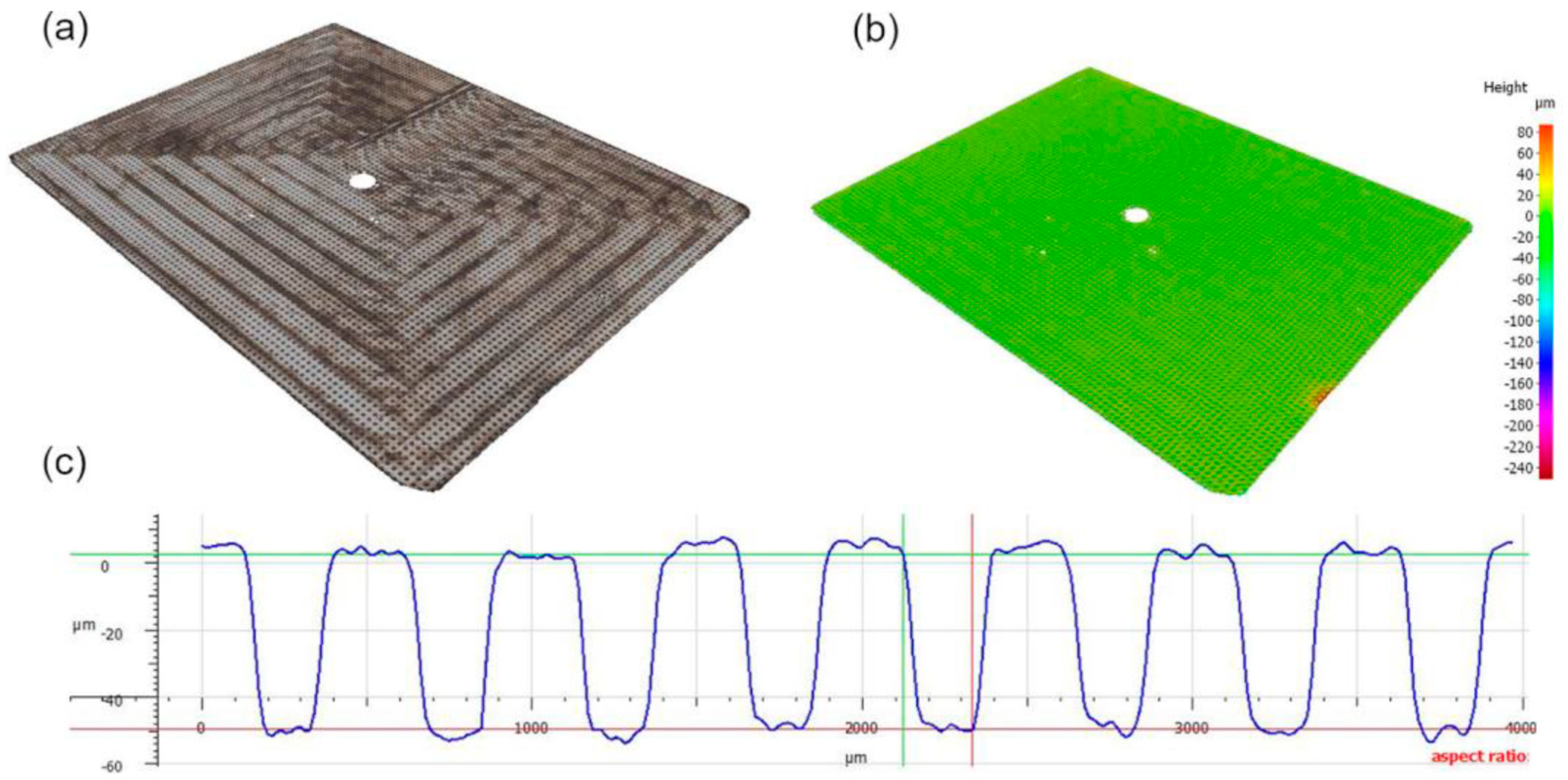
The texturing geometry for the aluminum preforms, shown in Figure 2, consists of circular holes with a diameter of 250 µm, depth of 50 µm, and areal density of 20% (spacing of 0.5 mm between the holes from center to center). In order to compare the performance of the laser-textured surfaces with conventional methods, ground and sand-blasted surfaces were also prepared according to industrial practice. In particular, grinding provides a relatively smooth surface, whereas sand-blasting produces a rougher surface characterized by a chaotic pattern. The roughness of the treated surfaces was measured using a Focus-Variation 3d optical microscope (Bruker Alicona, Graz, Austria) and the Sa roughness data are respectively 0.15 μm for ground and 3.2 μm for sand-blasted surfaces.
Contextually, monolithic blocks of cast/forged A356-T6 and DMLS AlSi10Mg alloy were machined to obtain the proper shape required by the testing standards. The motive behind this is to compare the mechanical behavior of hybrid specimens with their current manufacturing counterparts.
Mechanical testing of the materials of this study includes microhardness, tensile, and fatigue tests. Tensile tests were carried out according to the standard ISO 6892-1:2009 using a Autograph AG-X plus 100kN universal testing machine (Shimadzu, Kyoto, Japan), fitted with Trapezium X software and TRViewX image acquisition). A constant displacement rate of 0.2 mm/min at ambient temperature was set for all tests. An axial fatigue test campaign was run using an Instron 8801 servo-hydraulic machine with 100 kN load cell (Instron, Norwood, MA, USA) under the following conditions: (i) stress ratio R = −1, (ii) frequency of 5 ~ 10 Hz. Testing was realized under stress control at three levels of stress amplitude: 140 MPa, 170 MPa, and 200 MPa. The procedures described in standard ISO 12107:2012 were thoroughly followed. The fracture surfaces were characterized using a Jeol JSM 6300 scanning electron microscopy (Jeol Akishima, Japan) with an acceleration voltage of 20 kV. Microhardness was measured using an Innovatest 400A microhardness tester with Vickers indenter (Innovatest Europe BV, Maastrich, The Netherlands) applying a load of 100 g for 15 s, in compliance with ISO 6507-1:1997. The microhardness of as-built monolithic samples was also measured and used as a reference for the hybrid material. Regarding microstructural characterization, samples of the different materials were prepared following standard metallographic preparation for aluminum alloys (grinding, polishing down to 0.3 microns, and etching with Weck’s reagent), then the microstructure was observed using a Nikon Microphot-FX optical microscope (Nikon Corporation, Tokyo, Japan).

3. Results and Discussion

The strength of the hybrid system was firstly evaluated under tensile load. The yield strength (YS), the ultimate tensile strength (UTS), and the ductility of different batches are reported in Figure 3, where an overview of the tensile test campaign performed on a representative number of samples is presented. In particular, the hybrid system is compared to homogeneous ones composed of A356 or DMLS material. The results show that the annealing/stress-relieving heat treatment (SR) greatly affects the mechanical properties of the cast/forged part, leading to a dramatic drop in YS and UTS. In particular, all the hybrid samples failed on the preform side at low stresses, showing very high ductility values, as reported in Figure 3b.
The extensive elongation values reported in Figure 3b and the neck formation observed in broken bars (Figure 4a) are due to an overaging of the preform material caused by the annealing/stress-relieving treatment (SR) adopted to reduce the brittleness of the DMLS side [22]. Therefore, the SR treatment, recognized as optimal for bulk DMLS parts, appears detrimental in the case of hybrid components. As-built and T6 hybrid bars also failed in the cast/forged preform sides, although the extent of necking was smaller compared to the annealed side with SR (Figure 4b,c), in agreement with the higher strength values and lower ductility reported in Figure 3. The mean UTS value is equal to 305 MPa in agreement with the A356-T6 aluminum alloy data reported elsewhere [14], in which the analyzed samples are manufactured by COBAPRESSTM, a casting/forging process principally used to produce aluminum parts for the automotive industry. It is worth noting that the final T6 treatment enhances the ductility of the hybrid system because it increases the ductility of the DMLS side without affecting the strength of the preform [23,24]. Images of fracture surfaces obtained by scanning electron microscopy (SEM) for both materials (cast/forged preform and DMLS) after T6 heat treatment are shown in Figure 4d–g. Extensive areas of ductile behavior are visible throughout in both samples (Figure 4d,f), with the dimples’ distribution more homogenous in the DMLS material due to its refined microstructure [24]. On the other hand, A356-T6, being processed by casting, shows some areas of brittle fracture (stepped cleavage planes) related to eutectic silicon platelets (Figure 4e), whereas the DMLS material does not exhibit brittle fracture and the dimples are much deeper (Figure 4g). These observations are corroborated by the lower values of ductility shown by A356-T6 when compared to DMLS T6 (Figure 3b). Finally, the strength of DMLS T6 is slightly higher than the values obtained with specimens made of A356-T6 (Figure 3a). This behavior is reflected in hybrid bars where the fracture of the preform indirectly proves the optimal resistance of the hybrid interface and, consequently, of a sound joint when static properties are considered. In this scenario, the different surface preparations do not affect the tensile behavior of the hybrid samples.
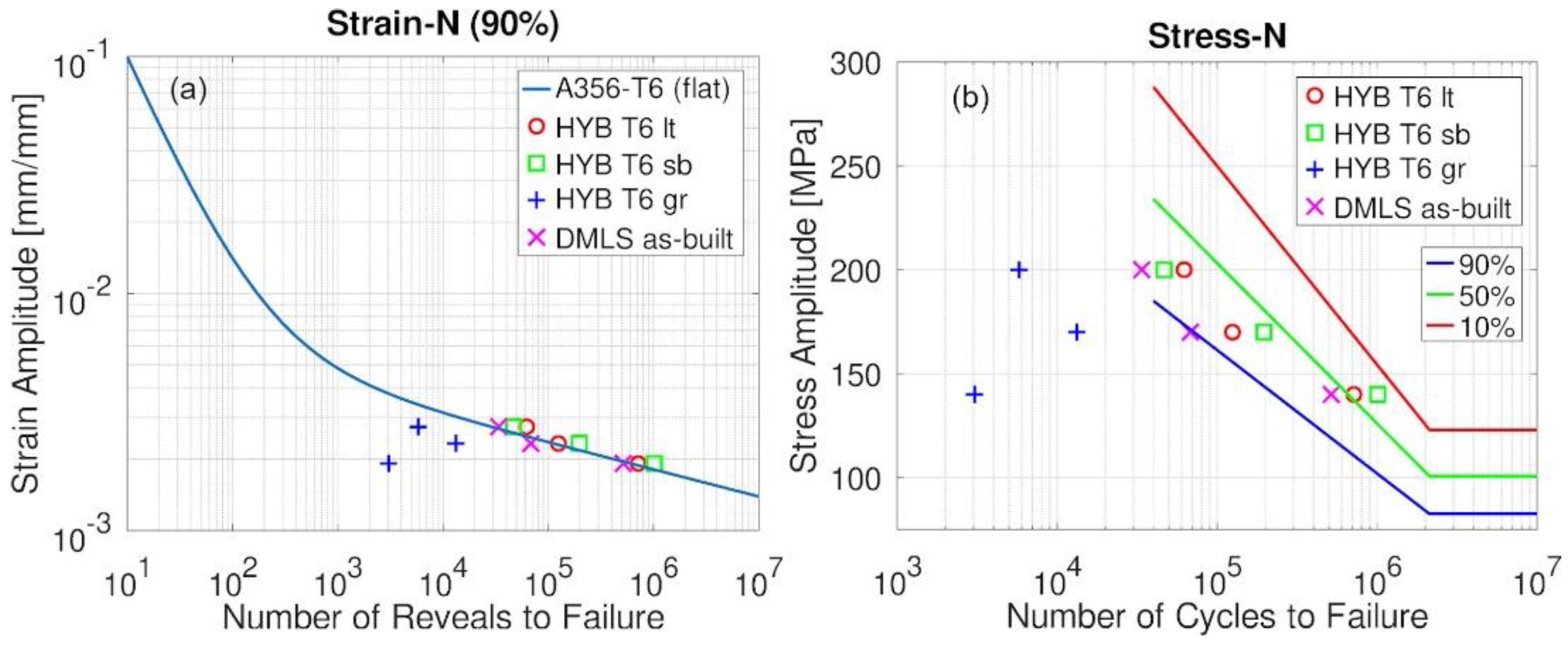
Concerning fatigue, although control of fatigue was achieved by applying stress (under stress in every case in the elastic regime), a conversion of the data was carried out to compare the results of hybrid samples with the 90% survival curve of the homogeneous A356-T6 counterpart (Figure 5a). Figure 5b shows the number of cycles to failure observed with different applied stresses, where the survival lines for 90%, 50%, and 10%, obtained from the extensive fatigue testing of homogeneous A356-T6, are included for comparison. The results of the hybrid samples lined up with the performance of homogeneous A356-T6 ones, except for fatigue samples ground at the preform/DMLS interface.
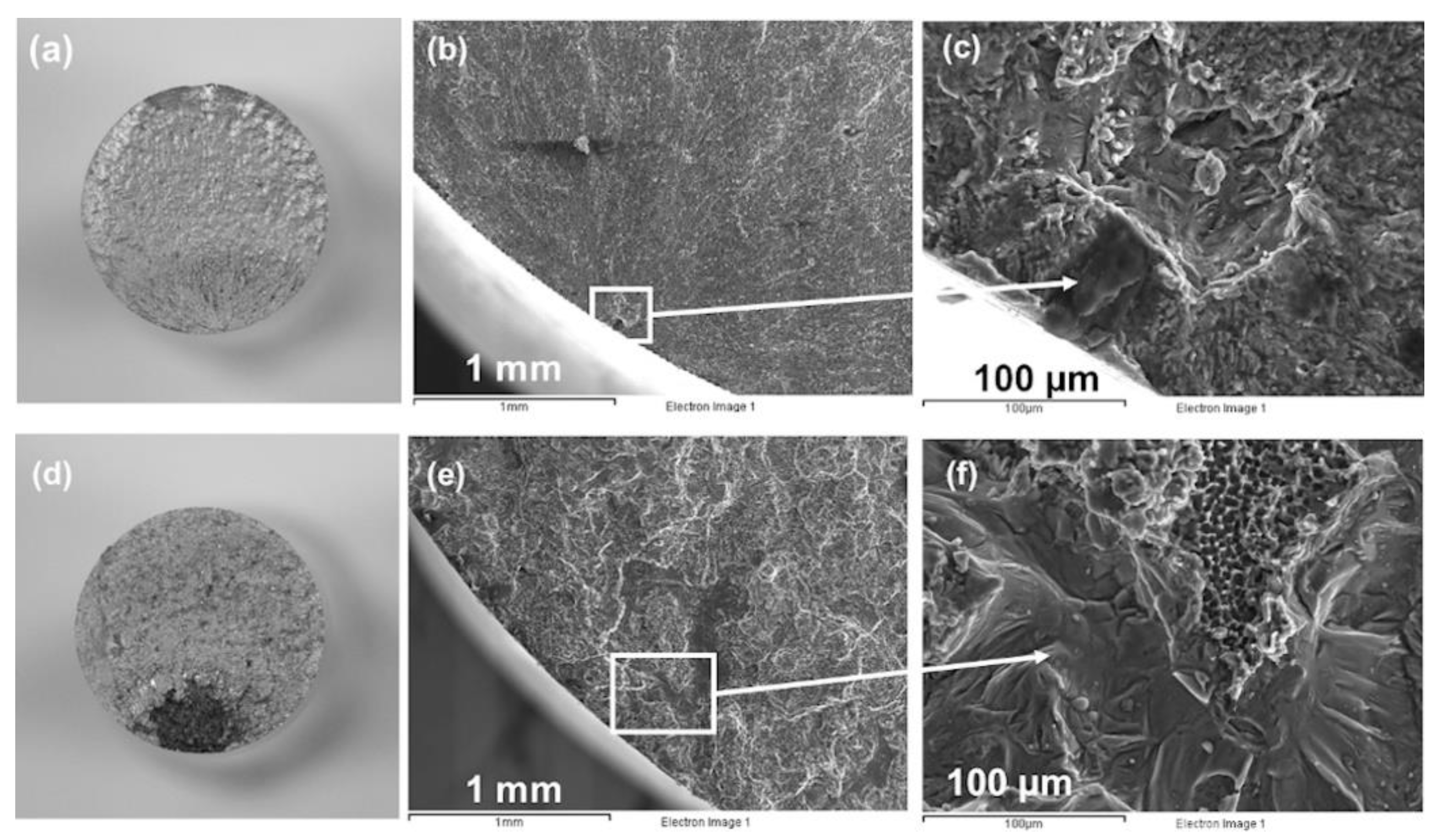
The laser-textured and sand-blasted hybrid samples suffered a fracture in the DMLS side (Figure 6a) attributable to the intrinsic defects caused by the DMLS technique (mainly pores); these defects, even if small, could be the source of crack nucleation (Figure 6b,c) [25]. It is well-known that stronger materials are more influenced by the presence of defects when fatigue resistance is analyzed. Therefore, the fact that the DMLS side is characterized by a higher strength means that the defects have a significant impact under fatigue loading; thus, all the fractures took place on that side, proving that the joint is strong enough. On the other hand, ground samples failed at the interface (Figure 6d) after a very low number of cycles (Figure 5a,b), revealing a weak joint between the preform and DMLS side. SEM images in Figure 6e,f show a crack initiation area, where a meaningful defect is present with an extensive lack of fusion and evidence of a fragile fracture. Therefore, fatigue results and the morphological characterization of the fracture reveal that the combination of the DMLS process and grinding surface preparation led to a defective interface that affects the resistance of the joint in fatigue. In particular, the formation of a pattern at the interface resulted in an improved joining when compared to the smoothest one (ground). It was not possible to quantitatively evaluate the impact of the chaotic (sand blasted) and regular (laser-textured) pattern on the mechanical behavior of hybrid specimens. Surely, the increased contact surface provided by the pattern helps to keep the powder layer compact and in place during the DMLS processing of the first few layers; not happening on a smooth surface caused the formation of important defects (such as improperly melted powder or a lack of fusion), promoting faster crack nucleation phenomena [26,27]. Despite the reduced number of specimens, it can be stated that the laser-textured and sand-blasted hybrid solutions are comparable, in fatigue, to the homogeneous cast/forged one.
Figure 7 reports an optical microscope image of the interface where the bottom is the preform material and the top is the DMLS part. The weld seams of the additive process are easily identifiable, while the black squares are the Vickers indenter’s marks. The different microstructures are clearly distinguishable, and the interface appears well-structured and without defects (grain boundary voids, cracking, detachment) under sand-blasting surface preparation, additive manufacturing process parameters standardized for AlSi10Mg and T6 heat treatment.
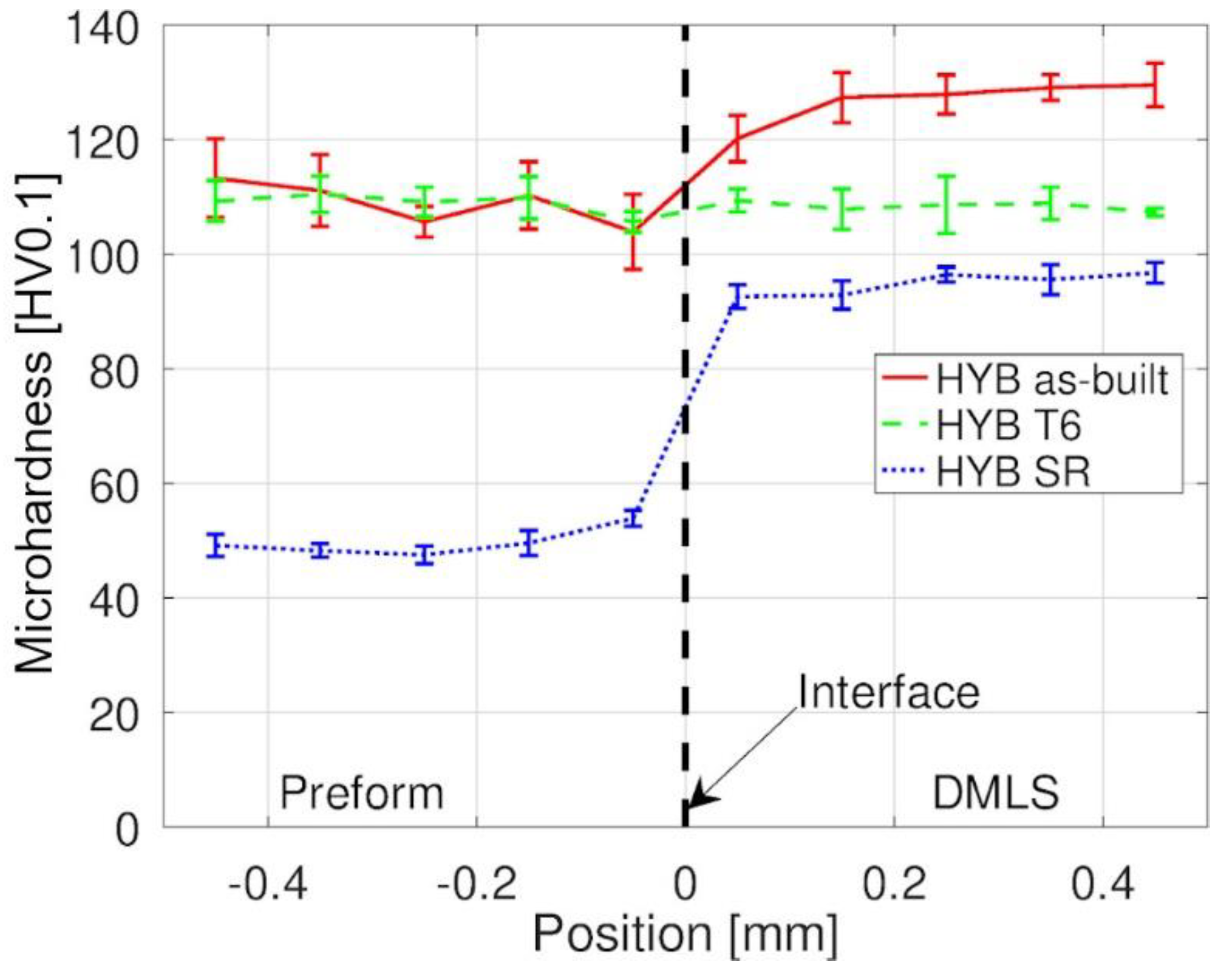
The microhardness of as-built monolithic samples is respectively 109 HV0.1 for A356-T6 and 122 HV0.1 for DMLS AlSi10Mg. The microhardness in the hybrid interface is reported in Figure 8. SR heat treatment also has a negative impact on A356-T6 hardness (reduction of about 50%) due to massive material overaging. As reported before, the annealing and stress-relieving treatment, conceived for reducing internal stresses in the DMLS part, impairs the strength of the cast and forged counterpart, resulting in inadequacies when manufacturing hybrid components. On the other hand, the as-built hybrid samples, where DMLS was deposited on a preform treated with optimum aging condition (T6), show a marked difference in hardness on both sides. The DMLS side is much harder thanks to the extremely fine microstructure developed during the quick cooling rate experienced during every laser pass. However, the heat input of the DMLS process affects the precipitates in the A356-T6 preform, resulting in a non-negligible reduction in hardness, due to a sort of overaging that took place in the relative heat-affected zone. Nevertheless, both materials maintain the microhardness measured in the monolithic samples far from the interface. Finally, performing an appropriate T6 treatment after the hybrid fabrication homogenizes the hardness at the interface and throughout the sample, and restores the preform weakening at the interface caused by the superheating introduced by the DMLS process. The hardness reduction of the DMLS side, when heat treated, is caused by the levelling of diffusions and the removal of internal tension that arose with the rapid crystallization of melted particles [22].

4. Conclusions

The present study reports the mechanical behavior of hybrid aluminum parts manufactured by a combination of both DMLS and casting/forging processes. AlSi10Mg and A356-T6 aluminum alloys were respectively selected for their composition compatibility and lightweight potential; both these alloy grades are already extensively used in the car industry. To reach the automotive homologation standards, the surfaces of chosen substrates were pretreated prior to deposition to improve the interface’s mechanical properties. The analysis of the results reveals that the annealing and stress-relieving heat treatment, usually adopted to reduce brittleness on the DMLS part, has a remarkable impact on the preform, leading to a dramatic reduction in the strength of the hybrid system. On the contrary, applying T6 heat treatment after the hybrid process proved to be the best option in terms of tensile strength, ductility, and hardness across the interface. In addition to previous research, different surface preparation types were investigated because it has been reported that they could enhance material bonding on the first layers of the additive manufactured parts. Among them, laser-texturing and sand-blasting represented the most effective methods since they can produce hybrid samples with proper mechanical properties (hardness, tensile strength, and fatigue) that are comparable to those of the homogeneous counterparts produced by conventional production technology, while still being compliant with automotive requirements. The choice between sand-blasting and laser-texturing depends straightforwardly on production volume and the specific application being addressed; the former employs less expensive equipment, while at the same time requires additional costs for cleaning the workspace to avoid the formation of production defects. Laser microprocessing with pulsed sources is a highly promising option due to its no-contact machining approach, its flexibility in processing different component sizes and shapes, its capacity to process a wide range of materials, and the possibility of fully integrating surface production in a digital environment based on CAD/CAM interfaces. This process presents advantages compared to other surface processing technologies in terms of eco-compatibility, easy manufacturability, and high accuracy and precision. For all these reasons, proving the structural integrity of a defined hybrid specimen, and in particular, an interfacial one, the present work explains a production methodology to support the car industry in exploiting the novel design concept in real applications.

Author Contributions

Conceptualization, all authors.; investigation, A.T., A.B., N.M., F.G., P.P.; interpretation of data, all authors; writing—original draft preparation, A.T.; writing—review and editing, all authors; funding acquisition, A.T., D.P., J.B. All authors have read and agreed to the published version of the manuscript.

Funding

This research has received funding from the European Union’s Horizon 2020 research and innovation program under grant number 723826 and EIT Raw Materials under project number 18089.

Institutional Review Board Statement

Not applicable.

Informed Consent Statement

Not applicable.

Data Availability Statement

This study did not produce any publicly archived datasets or databases. The data presented in this study are available on request from the corresponding author.

Conflicts of Interest

The authors declare no conflict of interest.

References

  1. Cischino, E.; Di Paolo, F.; Mangino, E.; Pullini, D.; Elizetxea, C.; Maestro, C.; Alcalde, E.; Christiansen, J.D. An advanced technological lightweighted solution for a Body in White. Transp. Res. Procedia 2016, 14, 1021–1030. [Google Scholar] [CrossRef] [Green Version]
  2. Li, Y.; Yu, S.; Chen, Y.; Yu, R.; Shi, Y. Wire and arc additive manufacturing of aluminum alloy lattice structure. J. Manuf. Process. 2020, 50, 510–519. [Google Scholar] [CrossRef]
  3. Sapardanis, H.; Pullini, D.; Gili, F.; Bajolet, J.; Maillol, N. Design optimisation for additive manufacturing: Reduce cost using lattice structures. In Proceedings of the SIA Multi-Material International Congress, Paris, France, 20–21 March 2019. [Google Scholar]
  4. Schmidt, M.; Merklein, M.; Bourell, D.; Dimitrov, D.; Hausotte, T.; Wegener, K.; Overmeyer, L.; Vollertsen, F.; Levy, G.N. Laser based additive manufacturing in industry and academia. CIRP Ann. Manuf. Technol. 2017, 66, 561–583. [Google Scholar] [CrossRef]
  5. Horn, T.J.; Harrysson, O.L.A. Overview of current additive manufacturing technologies and selected applications. Sci. Prog. 2012, 95, 255–282. [Google Scholar] [CrossRef]
  6. Huang, R.; Riddle, M.; Graziano, D.; Warren, J.; Das, S.; Nimbalkar, S.; Cresco, J.; Masanet, E. Energy and emissions saving potential of additive manufacturing: The case of lightweight aircraft components. J. Clean. Prod. 2016, 135, 1559–1570. [Google Scholar] [CrossRef] [Green Version]
  7. Huang, S.H.; Liu, P.; Mokasdar, A.; Hou, L. Additive manufacturing and its societal impact: A literature review. Int. J. Adv. Manuf. Technol. 2013, 67, 1191–1203. [Google Scholar] [CrossRef]
  8. Merklein, M.; Junker, D.; Schaub, A.; Neubauer, F. Hybrid additive manufacturing technologies—An analysis regarding potentials and applications. Phys. Procedia 2016, 83, 549–559. [Google Scholar] [CrossRef] [Green Version]
  9. Meiners, F.; Ihne, J.; Jürgens, P.; Hemes, S.; Mathes, M.; Sizova, I.; Bambach, M.; Hamar-Saleh, R.; Weisheit, A. New hybrid manufacturing routes combining forging and additive manufacturing to efficiently produce high performance components from Ti-6Al-4V. Procedia Manuf. 2020, 47, 261–267. [Google Scholar] [CrossRef]
  10. Bambach, M.; Sviridov, A.; Weisheit, A.; Schleifenbaum, J. Case studies on local reinforcement of sheet metal components by laser additive manufacturing. Metals 2017, 7, 113. [Google Scholar] [CrossRef] [Green Version]
  11. Bambach, M.; Sizova, I.; Sydow, B.; Hemes, S.; Meiners, F. Hybrid manufacturing of components from Ti-6Al-4V by metal forming and wire-arc additive manufacturing. J. Mater. Process. Technol. 2020, 282, 116689. [Google Scholar] [CrossRef]
  12. Kumar, J.; Singh, D.; Kalsi, N.S.; Sharma, S.; Pruncu, C.I.; Pimenov, D.Y.; Rao, K.V.; Kapłonek, W. Comparative study on the mechanical, tribological, morphological and structural properties of vortex casting processed, Al–SiC–Cr hybrid metal matrix composites for high strength wear-resistant applications: Fabrication and characterizations. J. Mater. Res. Technol. 2020, 9, 13607–13615. [Google Scholar] [CrossRef]
  13. Penchev, P.; Bhaduri, D.; Carter, L.; Mehmeti, A.; Essa, K.; Dimov, S.; Adkins, N.J.E.; Maillol, N.; Bajolet, J.; Maurath, J.; et al. System-level integration tools for laser-based powder bed fusion enabled process chains. J. Manuf. Syst. 2019, 50, 87–102. [Google Scholar] [CrossRef]
  14. Perrier, F.; Desrayaud, C.; Bouvier, V. Microstructural and mechanical evolutions during the forging step of the COBAPRESS, a casting/forging process. In Proceedings of the 13th International Conference on Aluminum Alloys, Pittsburgh, PA, USA, 3–7 June 2012. [Google Scholar]
  15. Zhu, M.; Jian, Z.; Yang, G.; Zhou, Y. Effects of T6 heat treatment on the microstructure, tensile properties, and fracture behavior of the modified A356 alloys. Mater. Des. 2012, 36, 243–249. [Google Scholar] [CrossRef]
  16. Pio, L.Y. Effect of T6 heat treatment on the mechanical properties of gravity die cast A356 aluminium alloy. J. Appl. Sci. 2011, 11, 2048–2052. [Google Scholar] [CrossRef] [Green Version]
  17. AlSi10Mg Material Data Sheet. Available online: https://www.eos.info/en/additive-manufacturing/3d-printing-metal/dmls-metal-materials/aluminium-al (accessed on 8 February 2021).
  18. Mann, V.; Krokhin, A.; Alabin, A.; Zmanovskiy, S.; Konkevich, V.; Redkin, I. Evolution of Aluminum Alloys Structure at Production Phases of 3D Products by Methods of Additive Technologies. In TMS 2017 146th Annual Meeting & Exhibition Supplemental Proceedings; The Minerals, Metals & Materials Series; Springer: Cham, Switzerland, 2017; pp. 49–59. [Google Scholar]
  19. Bourell, D.; Kruth, J.P.; Leu, M.; Levy, G.; Rosen, D.; Beese, A.M.; Clare, A. Materials for additive manufacturing. CIRP Ann. Manuf. Technol. 2017, 66, 659–681. [Google Scholar] [CrossRef]
  20. Takata, N.; Kodaira, H.; Sekizawa, K.; Suzuki, A.; Kobashi, M. Change in microstructure of selectively laser melted AlSi10Mg alloy with heat treatments. Mater. Sci. Eng. A 2017, 704, 218–228. [Google Scholar] [CrossRef]
  21. Emadinia, O.; Ramalho, A.M.; de Oliveira, I.V.; Taber, G.A.; Reis, A. Influence of Surface Preparation on the Interface of Al-Cu Joints Produced by Magnetic Pulse Welding. Metals 2020, 10, 997. [Google Scholar] [CrossRef]
  22. Ceschini, L.; Morri, A.; Morri, A.; Toschi, S.; Johansson, S.; Seifeddine, S. Effect of microstructure and overaging on the tensile behavior at room and elevated temperature of C355-T6 cast aluminum alloy. Mater. Des. 2015, 83, 626–634. [Google Scholar] [CrossRef]
  23. Maskery, I.; Aboulkhair, N.T.; Tuck, C.; Wildman, R.D.; Ashcroft, I.A.; Everitt, N.M.; Hague, R.J.M. Fatigue performance enhancement of selectively laser melted aluminium alloy by heat treatment. In Proceedings of the 26th Annual International Solid Freeform Fabrication Symposium, Austin, TX, USA, 8–12 August 2015. [Google Scholar]
  24. Li, W.; Li, S.; Liu, J.; Zhang, A.; Zhou, Y.; Wei, Q.; Yan, C.; Shi, Y. Effect of heat treatment on AlSi10Mg alloy fabricated by selective laser melting: Microstructure evolution, mechanical properties and fracture mechanism. Mater. Sci. Eng. A 2016, 663, 116–125. [Google Scholar] [CrossRef]
  25. Tang, M.; Pistorius, P.C. Oxides, porosity and fatigue performance of AlSi10Mg parts produced by selective laser melting. Int. J. Fatigue 2017, 94, 192–201. [Google Scholar] [CrossRef]
  26. Suraratchai, M.; Limido, J.; Mabru, C.; Chieragatti, R. Modelling the influence of machined surface roughness on the fatigue life of aluminium alloy. Int. J. Fatigue 2008, 30, 2119–2126. [Google Scholar] [CrossRef] [Green Version]
  27. Nanninga, N.; White, C. The relationship between extrusion die line roughness and high cycle fatigue life of an AA6082 alloy. Int. J. Fatigue 2009, 31, 1215–1224. [Google Scholar] [CrossRef]
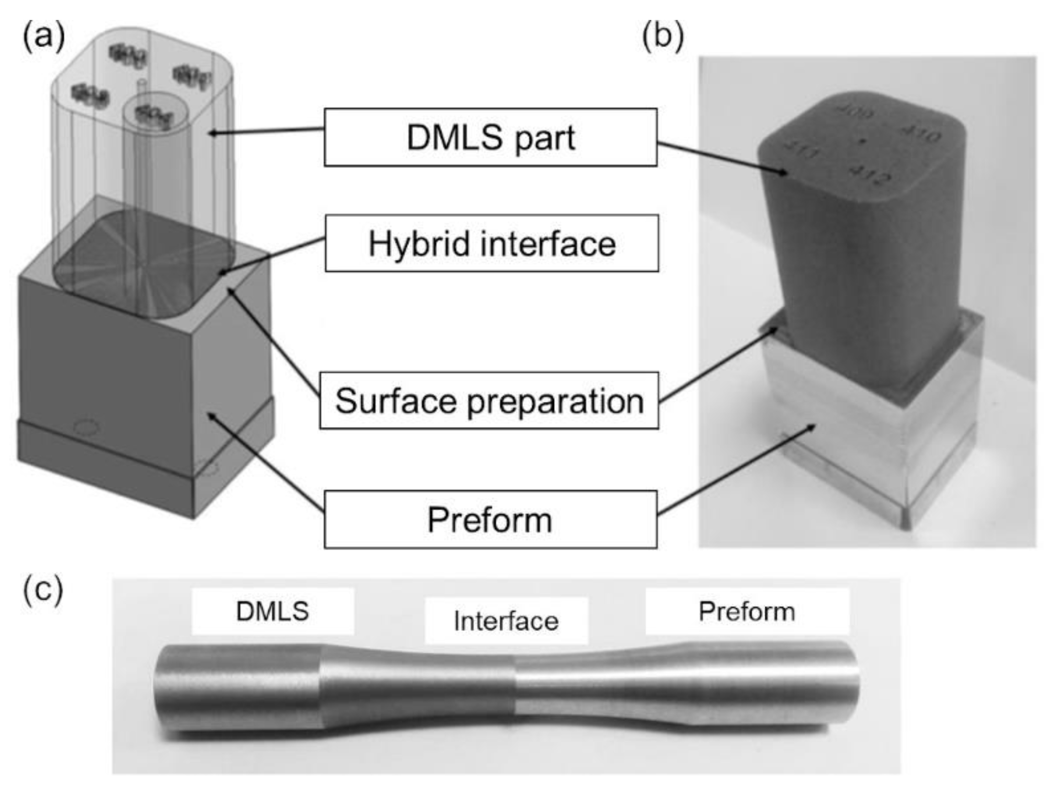
Figure 1. (a) sketch of the raw hybrid block with the bars to be wire-cut, (b) raw hybrid block, (c) machined fatigue hybrid bar.
Metals 11 00522 g001
Figure 2. Laser-textured surface of a preform: (a) 3D view (b) pseudocolor representation of the 3D view and (c) extracted profile view of a couple of randomly selected dimples.
Metals 11 00522 g002
Figure 3. Results of tensile test campaign: (a) yield strength and ultimate tensile strength, (b) ductility (reduction in area and elongation at break).
Metals 11 00522 g003
Figure 4. Images of broken hybrid specimens after the tensile test: (a) annealed (SR), (b) as built, and (c) T6 heat treated. SEM images of fracture surface: (d,e) A356-T6 sample at low and high magnifications respectively, showing abundant dimple formation and typical areas of brittle fracture; (f,g) T6-treated DMLS AlSi10Mg sample at low and high magnifications respectively, showing homogeneous dimple formation.
Metals 11 00522 g004
Figure 5. (a) strain number of reversals curve, (b) stress number of cycles to failure curve (Wöhler curve). Three levels of amplitude of stress were considered: 140 MPa, 170 MPa, and 200 MPa (all below the Yield Strength).
Metals 11 00522 g005
Figure 6. (a,d) views of broken fatigue bars; (b,e) SEM images with defects; (c,f) relative high magnification of, respectively, a hybrid sand-blasted and a ground bar.
Metals 11 00522 g006
Figure 7. (a) Microscope image and (b) relative high magnification of hybrid interface with Vickers indents. The lower part is the A356-T6 preform while the upper part is made of DMLS AlSi10Mg.
Metals 11 00522 g007
Figure 8. Microhardness of hybrid samples with different heat treatments. The left side comprises microhardness measurements on the preform side while the DMLS is on the right.
Metals 11 00522 g008
Table 1. Chemical composition (in wt. %) of the alloys used in this study.
ElementsAlSiMgTiFeCuNiZnSnMn
A356-T6Bal.6.980.350.150.100.010.013<0.015<0.005<0.005
AlSi10MgBal.9–110.25–0.45<0.150.550.050.050.100.050.45
Table 2. Laser processing parameters for the laser-texturing of the aluminum blocks.
ParametersUnitsValues
PowerWMax (4.2)
FrequencykHzMax (500)
Scanning speedm/s2
Beam spot diameterµm30
Wavelengthnm1030
Laser source Fs fiber laser (310 fs)
Hatch strategy 90 deg hatch direction change in each layer
Hatch pitchµm5
Publisher’s Note: MDPI stays neutral with regard to jurisdictional claims in published maps and institutional affiliations.