Article

Effect of Sigma Phase in Wire Arc Additive Manufacturing of Superduplex Stainless Steel

1
Department of Materials and Nanotechnology, SINTEF Industry, 7465 Trondheim, Norway
2
Department of Materials Science and Engineering, Norwegian University of Science and Technology, 7491 Trondheim, Norway
*
Author to whom correspondence should be addressed.
Metals 2021, 11(12), 2045; https://doi.org/10.3390/met11122045
Submission received: 16 November 2021 / Revised: 7 December 2021 / Accepted: 13 December 2021 / Published: 17 December 2021
(This article belongs to the Special Issue Wire Arc Additive Manufacturing of Metallic Components)

Abstract

:
In the present study, the thermal program in wire and arc additive manufacturing has been varied in terms of heat input and interpass temperature. Three walls were completed with subsequent Charpy V impact toughness and crack-tip opening displacement fracture toughness, together with a detailed microstructure characterization using light microscopy and scanning and transmission electron microscopy. The results clearly demonstrate that the formation of sigma phase may deteriorate the toughness of superduplex components. Such formation may take place under prolonged cooling time, which may occur when subsequent passes are deposited with too high interpass temperatures. This transformation behavior may limit the productivity in additive manufacturing of such steels and care must be taken in selection of proper combination of arc energy and interpass temperature.

1. Introduction

Additive manufacturing (AM), or 3D printing, has become a popular production method in the past decade. Compared with powder-based AM techniques, which usually employ laser or electron beams as heat sources, Martina et al. [1], Szoost et al. [2], and Willliams et al. [3] have all found that the wire-arc additive manufacturing (WAAM) has shown advantages in manufacturing large-scale components due to high deposition rate, high material utilization rate, low production and equipment cost, and high equipment flexibility and scalability. This is the reverse of conventional subtractive production involving casting and/or forming with final cutting and machining with excessive material removal from the final product.
WAAM can be applied for most metals and alloys that are weldable with fusion welding techniques. Concerning corrosion resistant alloys, both nickel superalloys and austenitic stainless steels have been subjected to WAAM. One example is the alloy 718 study by Asala et al. [4] demonstrating extensive formation of eutectic solidification microconstituents including Laves and MC-type carbide phases due to microsegregation of Nb. The γ′ (Ni3Al) is the primary precipitation strengthening phase in this alloy. Although the Ni-based alloys initially were developed for high temperature applications, they have excellent corrosion properties, which made them popular for the oil and gas industry.
Type 304 austenitic stainless steel was studied by Haden et al. [5]. They found that the wear rate declined in the direction of the weld deposition, indicating that the material wear resistance and strength are graded along the deposition path. Anisotropy in strength was also found by Ji et al. [6], which was explained by different grain boundary strengthening effects between the transverse direction and longitudinal direction.
Rodriguez et al. [7] manufactured 316L austenitic stainless steel grade by the cold metal transfer (CMT) and TopTIG processes. After process optimization, the authors reported material deposition rates of up to 3.7 kg/h and above 2 kg/h for CMT and TopTIG, respectively. They found some anisotropy in mechanical properties in the as-built state with lower strength values in the vertical (Z) orientation. WAAM of 17-4 PH martensitic stainless steel is reported by Martina et al. [8]. They found that solution heat treatment after deposition completion enhanced the strength to the base plate level. Caballero et al. [9] showed that direct aging solution treatment resulted in a reduction of ductility by nearly 50%, possibly due to formation of intermetallic phases.
Duplex stainless steel is a popular material for oil and gas applications, but there are very limited results available from additive manufacturing. Eriksson et al. [10] concluded that additive manufacturing of superduplex stainless steels by wire and arc process is feasible. Their microstructure observations consisted of low ferrite volume fraction, precipitation of Cr nitrides in the heat affected zone (HAZ) towards the building plate and formation of secondary austenite in reheated areas. The authors stated that the harmful sigma (σ) phase did not form due to the low heat input employed. Sigma phase precipitation dramatically decreases the toughness of duplex stainless steel [11,12,13], and a very low amount is necessary, i.e., as low as 1 vol% has been reported to cause a 50% reduction of the initial toughness [14]. Other intermetallics are also unfavorable to the properties of superduplex stainless steel, but not to the same extent as sigma. One of these is the body-centered cubic (bcc) chi (χ) phase (Fe35Cr12Mo10 [15]), which is also studied here.
The present investigation was carried out to assess WAAM as a candidate for rapid repair of subsea or topside components to keep a short down time. In addition, whether WAAM is an alternative for building components is evaluated. In the experimental part, a subgoal was to provoke formation of the sigma phase by using higher interpass temperatures than usual, which provides slower cooling through the critical temperature range where the phase is formed. The work clearly shows that the sigma phase may form under the deposition conditions using high interpass temperature. This fact may have negative consequences for the WAAM productivity of superduplex components, apart from the option of rebuilding the initial properties through controlled post WAAM heat treatment procedures.

2. Materials and Methods

2.1. Materials

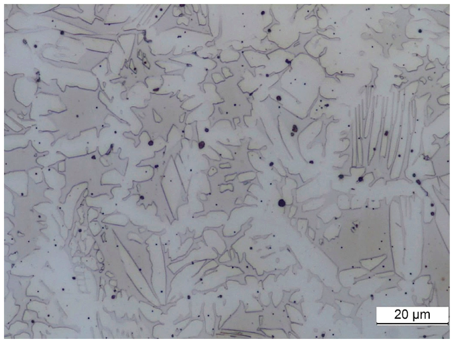
The welding wire selected for this work was 1.2 mm superduplex steel wire with high Ni content (9.5%) and 0.6% W. The high Ni content is added to stabilize austenite, but in the present study it results in low ferrite content approaching an unacceptable level. A 12 mm thick building plate of 2507 superduplex steel was used. Their chemical composition is outlined in Table 1. The plate has yield and tensile strength of 662 and 834 MPa, respectively, for a ferrite volume fraction of 0.48. Its microstructure is shown in Figure 1.

2.2. Deposition of Layers

Deposition of layers were performed with the metal inert gas (MIG) process using the parameters contained in Table 2. It is seen that W2 was deposited with slightly lower heat input than the two others. The travel speed was kept constant at 7 mm/s. The current was adjusted through changes in the wire feed rate. However, the largest difference was that W1 and W2 were allowed longer cooling time before the next layer was deposited. W1 and W2 had a delay of 6 min between each layer, while W3 had only a 2 min delay. The shielding gas was Mison® 2, consisting of Argon, 2% CO2, and 0.03% NO, using a flow rate of 20 L/min. The current wall depositions constituted 17 layers for W1 and 16 layers for W2 and W3. The deposition length was 230 mm, and the minimum height was set to 4 mm. The other deposition results are outlined in Table 3.

2.3. Testing and Characterization

The completed walls were cut perpendicular to the deposition direction to carry out macroscopic inspection, Charpy V notch and crack tip opening displacement (CTOD) testing, and metallographic evaluation of hardness and microstructures. Three Charpy V notch subsized samples with 5 mm × 10 mm cross section and 55 mm length were cut and machined with the length axis parallel with the deposition direction. The notch was positioned with the fracture surface perpendicular to the deposition direction (Figure 2). A total of 3 parallel specimens were tested. The absorbed energy of subsized specimens was multiplied by a factor of 2 for conversion to full size, in agreement with the DNV GL standard OS-F101 (2013). As for the Charpy samples, 3 parallel subsized 5 mm × 10 mm CTOD specimens were tested. Both Charpy and CTOD specimens were tested at a temperature of −46 °C.
Vickers pyramid hardness measurements (HV10, with 10 kg force) were carried out along vertical and horizontal traverses.
The quantitative microstructure characterization was performed with a light microscope. Scanning electron microscopy (SEM) with energy-dispersive X-ray spectroscopy (EDX) and electron back scattered diffraction (EBSD) were carried out in a Hitachi SU-6600 SEM (Hitachi High-Tech Corporation, Tokyo, Japan) at 20 kV. Transmission electron microscopy was done using a JEOL JEM-2100F (JEOL Ltd., Tokyo, Japan) operated at 200 kV. Samples for SEM and TEM were prepared by electropolishing.
Hough indexing of EBSD patterns was performed with the TSL OIM DC software (v7.3, EDAX, Mahwah, NJ, USA). Dictionary indexing (DI) was conducted with the open-source kikuchipy Python library [16], using dynamically simulated master patterns and orientation sampling obtained with EMsoft v5.0 [17,18]. Dictionaries of simulated patterns were populated by orientations sampled with an average angular step size of 1.4°. Patterns were projected from master patterns in the square Lambert projection onto the detector using biquadratic interpolation with a fixed projection center. Static and dynamic background corrections were performed on experimental patterns prior to indexing. Experimental and dictionary patterns were compared using the normalized cross-correlation (NCC), r. No orientation refinement was performed after DI.

3. Results and Discussion

3.1. Macroscopic Inspection

An inspection of cross sections of the deposited walls revealed that the walls did not contain any weld defects (Figure 2). The sample deposited with the medium heat input (W1) is built vertically in a straight line. By contrast, samples W2 and W3 with higher interpass temperatures seem to be much less stable during building. For certain individual beads, the viscous melt is flowing by a combination of relatively high temperature of the previous pass and gravity. High interpass may thus hamper a proper geometry precision during production.

3.2. Hardness

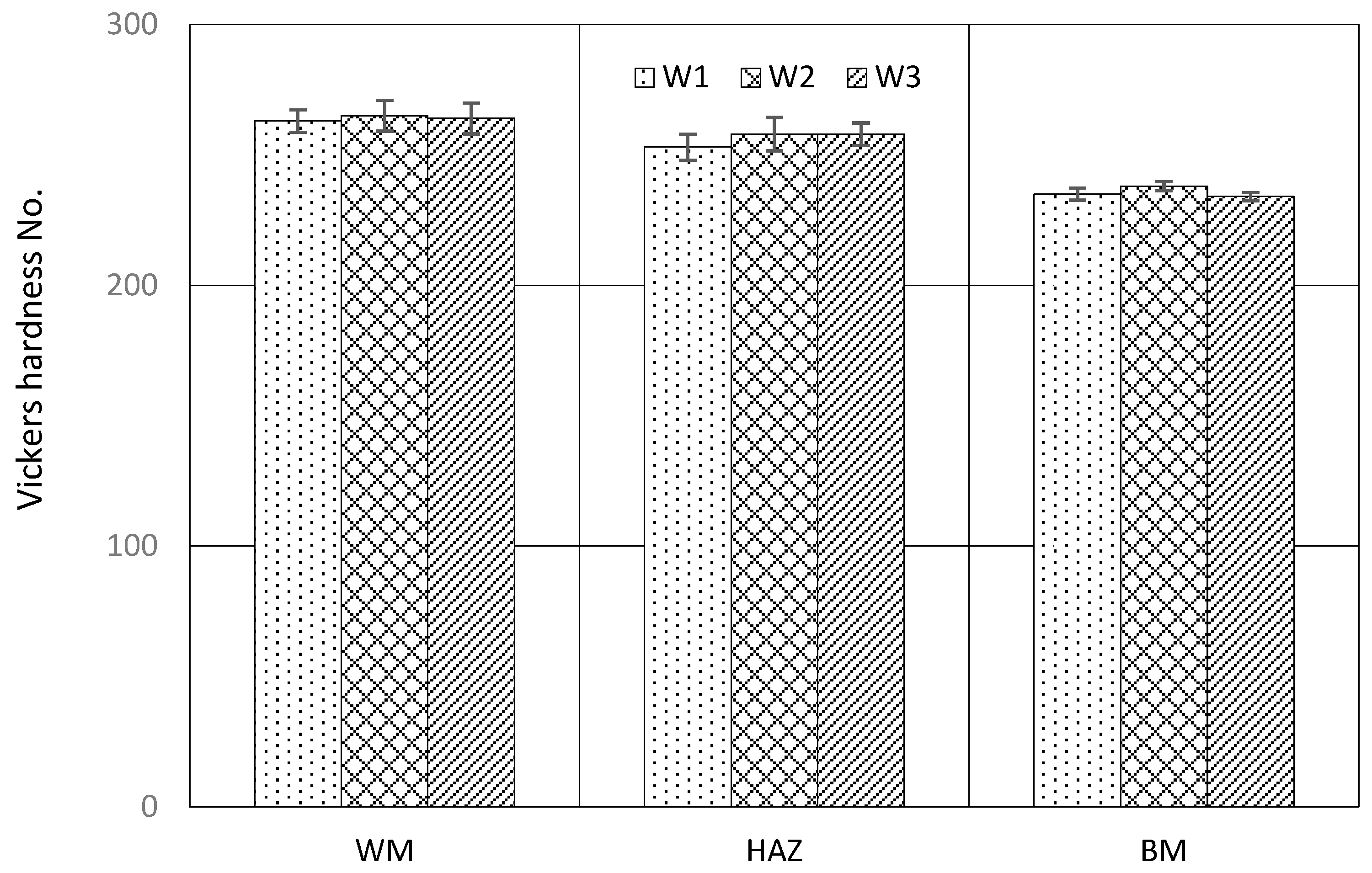
The hardness measurements demonstrated that the walls have low HV10 levels. The data plotted in Figure 3 revealed that the weld metal had the highest HV values, around 265, independent of employed heat input and interpass temperature. The base metal hardness was around 235 HV10, while the HAZ values were slightly below 260. The measured hardness is thus nearly independent of the thermal program employed in the present investigation, despite the different microstructures formed on cooling.

3.3. Charpy V Toughness

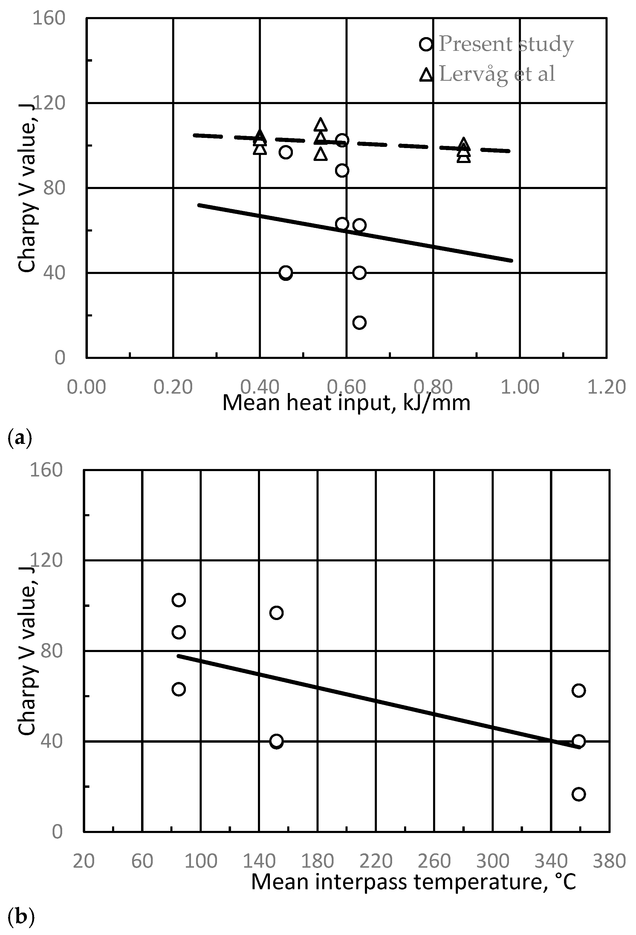
The Charpy V test results are plotted versus the mean heat input and mean interpass temperature in Figure 4a and Figure 4b, respectively. Although there is an apparent reduction in toughness with increasing heat input in Figure 4a, the fall in toughness for a heat input of 0.63 kJ/mm is due to the high interpass temperature employed resulting in sigma phase formation. Obviously, there is much better correlation with the interpass temperature, which slows down the cooling rate, promoting formation of the σ phase. The lowest Charpy value was found to be 17 J. These aspects will be further discussed in the microstructure Section 3.5 and Section 3.6.

3.4. Fracture Toughness

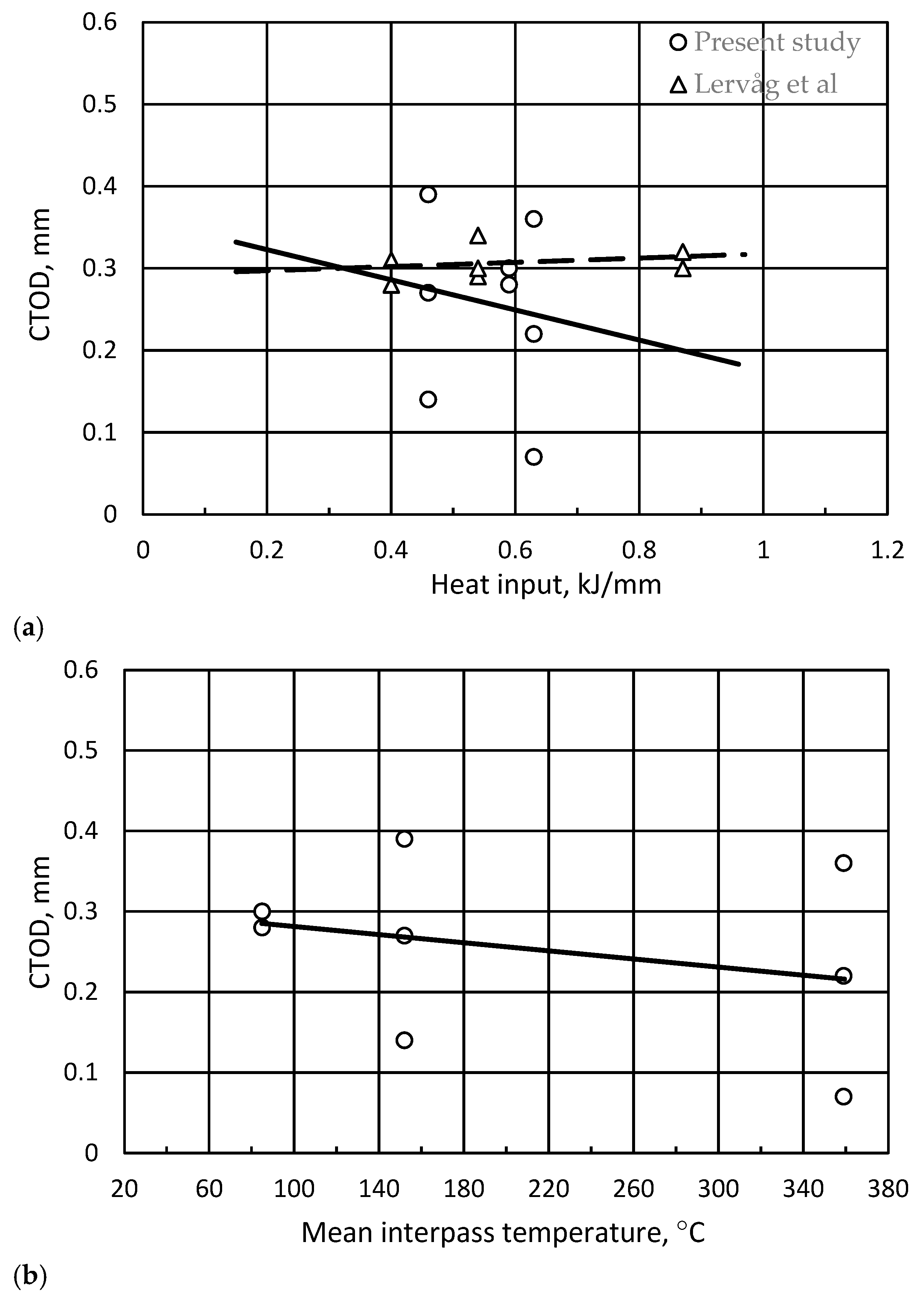
The CTOD results are plotted in Figure 5a,b versus the heat input and the interpass temperature, respectively. For the test temperature of −46 °C, the fracture toughness is slightly enhanced by an increase in the heat input (Figure 5a). For a heat input of 0.63 kJ/mm, the CTOD value vary from 0.07 mm to 0.36 mm. The toughness was also relatively low for a heat input of 0.46 kJ/mm, with values ranging from 0.14 to 0.39. In Figure 5b, the mean interpass temperature is found to reduce the fracture toughness, suggesting that the cooling rate was sufficiently low to form sigma. For the test temperature of −20 °C, the data from Lervåg et al. [19] showed that the toughness was nearly independent of heat input, which is reasonable since no sigma phase was found.

3.5. Quantitative Microstructure Analyses

Due to the high alloying level in superduplex stainless steels, their microstructures appear to be rather complex. The ferrite phase has a higher diffusion rate, and accordingly, most second phase precipitation takes place here. The intermetallic precipitations are of greatest interest due to their influence on the mechanical properties and corrosion resistance. These effects are further enhanced by a differential distribution of the alloying elements in the ferritic (ferrite formers) and austenitic phases (austenite formers). The extensive metallurgical changes taking place in cooling of superduplex stainless steel from high temperatures include solidification, solid state phase transformation from ferrite to austenite followed by Cr nitride precipitation, eventual formation of intermetallic compounds, and carbide precipitation. At the lowest temperatures (e.g., 475 °C), a distinct embrittlement may occur. The cause of this embrittlement has been recognized by Fisher et al. [20] and was related to precipitation of a non-magnetic chromium-rich α′ phase. The decomposition of the solid solution by a spinodal mechanism was due to an unstable solid solution at lower temperatures. They reported that the composition of this bcc precipitate ranges from 61 to 83 wt% Cr. In the present investigation, this kind of embrittlement has not been observed and must also be avoided in WAAM to retain the desired properties.
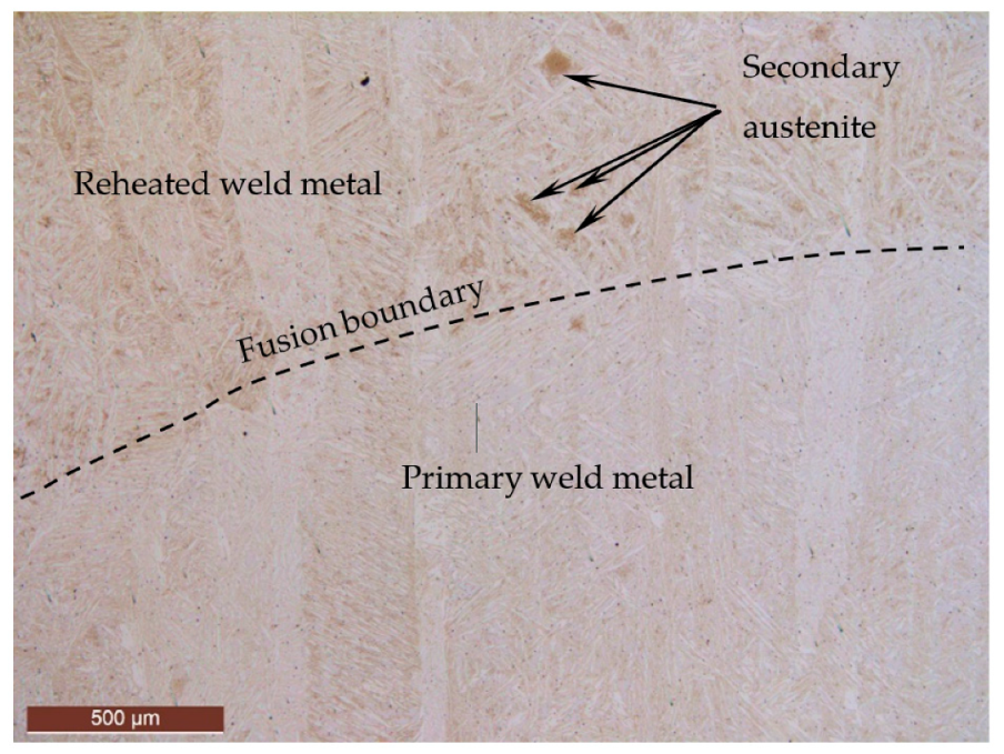
Examples of microstructures are contained in Figure 6, Figure 7 and Figure 8. Figure 6 shows an overview with primary (no reheating) and reheated regions, with the fusion boundary pointed out by the black dotted line. The figure reveals the epitaxial solidification takes place. In Figure 7 and Figure 8, there is quite different austenite appearance (white phase) including polygonal and acicular shapes, as well as more Widmanstätten-like austenite. It is also shown that there is a substantial number of visible non-metallic inclusions in the deposited walls.
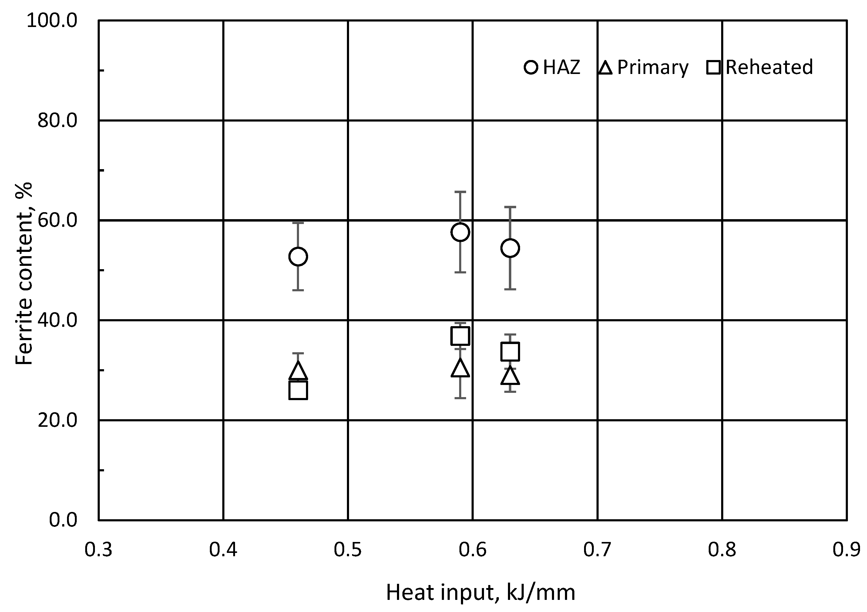
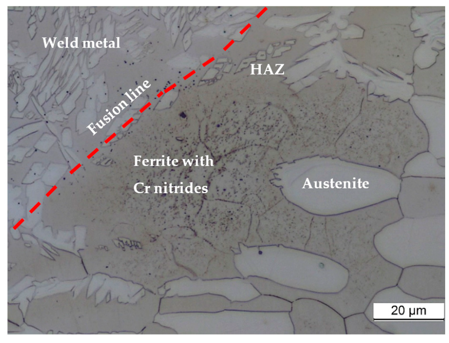
Quantitative microstructure analyses were performed in HAZ, non-reheated and reheated weld metal, and within different layers. The result for the ferrite volume fraction is plotted in Figure 9. As evidenced, the amount of ferrite in the HAZ (region towards the building plate) varied quite considerably; the microstructure is inhomogeneous with austenite formation along prior ferrite grain boundaries, Figure 10. The ferrite amount scattered from 39 to 77 vol%. Based on average values there was a slight decrease in ferrite with increasing heat input and interpass temperature. The ferrite fraction will obviously be strongly influenced by the grid positioning in point counting. Therefore, the number of point-counting areas was as high as 20 to achieve decent statistics. As observed for the HAZ, the ferrite content in the primary, non-reheated region was slightly reduced with increasing heat input.
Here, ferrite was present in lower amount than in the HAZ, i.e., 22–37 vol%. This fact agrees with the higher Ni content in the wire. The scatter in the ferrite fraction was also lower. Somewhat higher fraction of ferrite was found for the reheated region, 26–41 vol%. Moreover, the ferrite fraction was lower in the upper layers, which agrees with an expected slower cooling with increasing wall height. In practice, the austenite fraction approached the maximum allowable limit. Using the same requirements as set to welding, the phase balance of ferrite-austenite is specified by API to be between 30–65% for base metal, 40–65% for HAZ, and 25–60% for weld zone, as specified in the API report [21]. Similarly, NACE MR0175 states that the ferrite fraction shall be between 35 and 65% for wrought and cast structures and 30 and 70% for weld zone root and un-reheated weld cap [22]. The higher Ni content in the wire seems to reduce the ferrite content through austenite stabilization, approaching an unacceptable low level. Moreover, Ni may also suppress ferrite stabilizing elements like Cr and Mo, which in turn, may promote the sigma formation under slow cooling.
Under certain conditions, when the weld heat cycle is combined with high interpass temperature, the following slow cooling rates through the temperature range of 900 to 650 °C will provide formation of the sigma phase. The data plotted in Figure 11 reveal that the volume fraction of sigma increases when the interpass temperature increases. The highest amount of sigma was 7 and 5.1% in the primary and reheated regions, respectively. Magnabosco has reported from isothermal heat treatment of a 22Cr-5.7Ni-3Mo duplex stainless steel that the nose of the C-curve occurred at 850 °C with 2–10 vol% sigma formed after around 0.1 h [23]. With the present chemical composition of 25Cr-9.5Ni-3.7Mo, which is higher alloyed than conventional duplex grade, the sigma formation is expected to be much faster.

3.6. SEM Examination

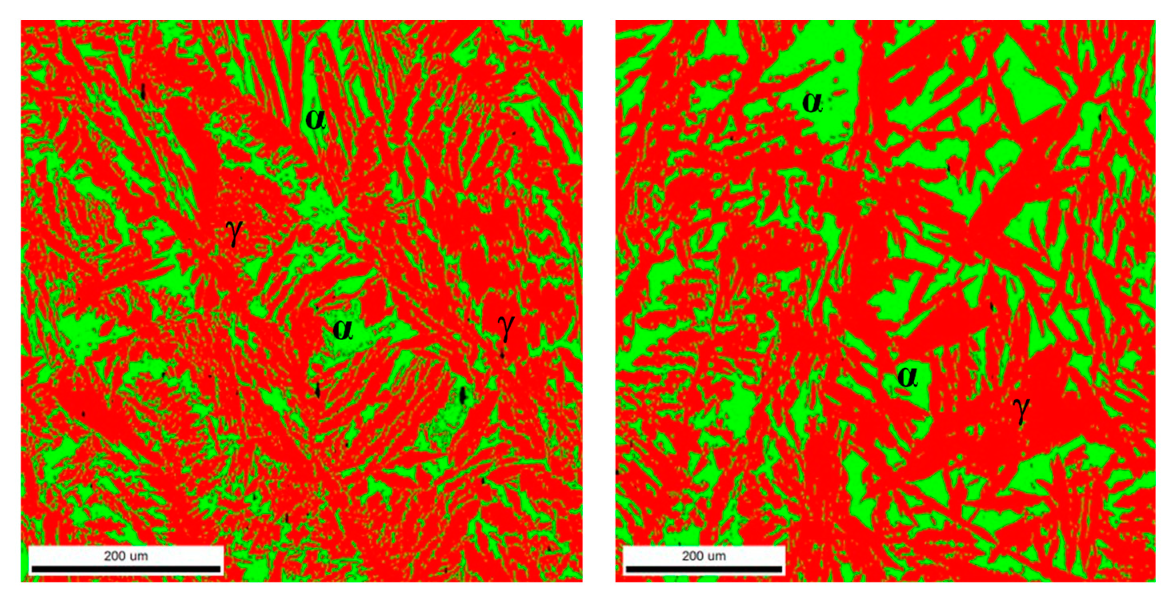
Samples were inspected in SEM to achieve more detailed information on the transformation behavior. Results from electron back-scatter diffraction (EBSD) are shown for the sigma free Wall 1 in Figure 12 for two different areas. Here, the austenite (red) and ferrite (green) fractions are 69–71 and 29–31%, respectively. In Figure 13, the formation of secondary austenite, γ2, is seen taking place in the ferrite regions. Secondary austenite is harmful to the corrosion resistance since it is formed under non-equilibrium conditions (fast heating and cooling with limited time for diffusion) and will therefore consist of a leaner chemistry, and hence, a lower pitting resistance equivalent than the original austenite. The deleterious effect of secondary austenite in superduplex stainless steels has been demonstrated in heat treatment experiments by Nilsson and Wilson [14]. They attributed toughness and pitting corrosion loss to the presence of secondary austenite at the ferrite/austenite phase boundaries. Nilsson et al. [24] found that the secondary austenite had lower chromium, molybdenum, and nitrogen than the primary austenite.
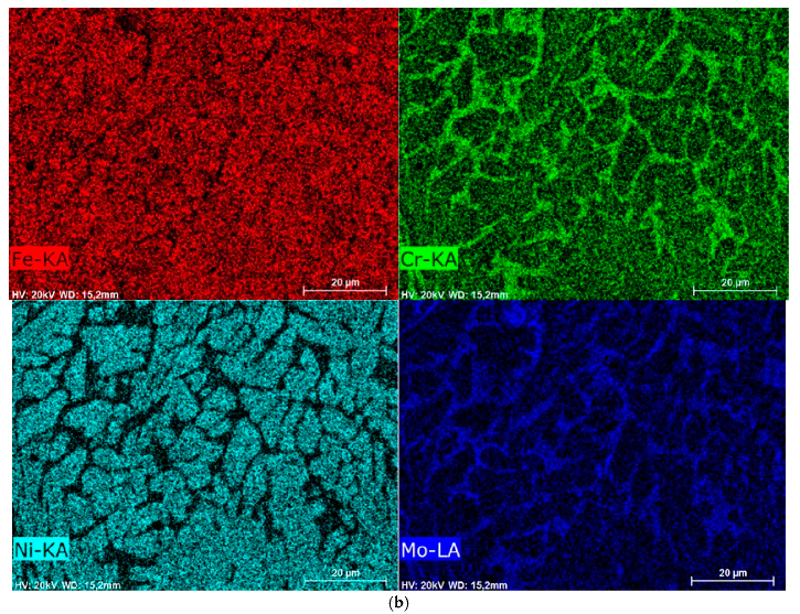
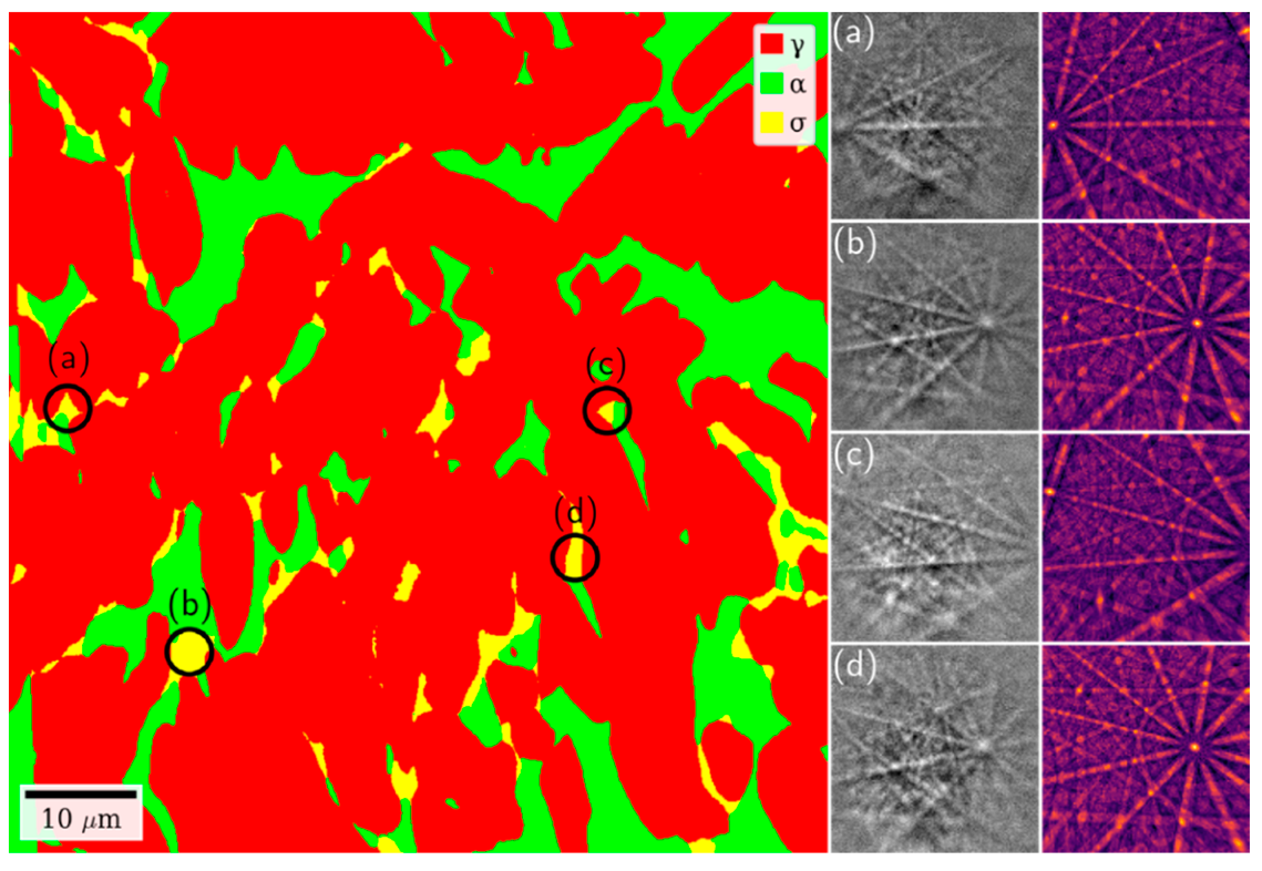
As clearly indicated in Figure 11, harmful σ has been observed. This is expected due to the high temperature between deposition of each layer, resulting in slow cooling rates, allowing the material to cool through the C-curve of the sigma phase. An inspection of Figure 14a reveals formation of sigma phase which appears as a fine network aligned along the ferrite grain boundaries and ferrite–austenite interfaces. In addition, there are few more blocky appearances of sigma. In Figure 14b, the EDX results are shown for the major elements in superduplex stainless steel, Fe, Cr, Ni, and Mo. It is evident that Fe, Cr, and Mo are present along grain and interphase boundaries and constitutes the sigma phase. Cr and Mo are specifically enriched in the sigma phase. By contrast, Ni is present inside ferrite and austenite grains only. These findings are supported by dictionary indexing EBSD results in Figure 15 showing a phase map with a significant amount of sigma along grain and interphase boundaries. Experimental patterns and the best matching simulated patterns from four regions highlighted in black circles are shown to the right in Figure 15, all with features of the characteristic c axis visible on the detector.
The C-curve for sigma is shifted towards higher temperatures and shorter times [26] with increasing alloying level. Therefore, it is always a potential risk of sigma to occur in multipass welding and WAAM, where the temperature–time cycles can be difficult to control due to productivity targets. In duplex stainless steel, sigma is normally avoided since its formation tends to be a slow process, meaning that prolonged holding in the range from 650 to 900 °C is required. The formation of sigma is taking place according to the eutectoid transformation (e.g., [27]):
α σ + γ 2
In the current study, formation of sigma has been seen to take place at ferrite grain and ferrite–austenite phase boundaries for Walls 2 and 3 with higher temperatures between layers. The nucleation stage will depend on the ferrite–ferrite grain and austenite–ferrite interface boundaries. The orientation relationships and coherency may both be important and early studies revealed that sigma phase formation was strongly affected by the crystallographic orientation relationship at the δ/γ interface [28]. The authors suggested consequently that highly coherent δ/γ interfaces can effectively suppress and delay sigma phase formation.
Once the first nucleus is formed, ferrite stabilizers Cr and Mo (and Si) diffuse from the ferrite to the sigma phase. As evidenced in Figure 14b, the Cr concentration is similar between the two phases of sigma and ferrite. On the austenite side, there is a Cr depletion when Cr diffuses into sigma. As sigma continues to grow into ferrite, the Cr depletion in austenite may be harmful to both mechanical properties and corrosion resistance along the austenite–sigma phase boundary. Growth of sigma may be relatively fast due to short diffusion distance of sigma stabilizing elements. By contrast to Cr, Mo (and Si) diffuses into sigma and has higher concentration here than in ferrite. The Ni concentration in sigma is much lower than in austenite, but is at the same level as in ferrite.
At a certain temperature during reheating of parts of the previous layer, secondary austenite starts to form in the ferrite. Since this takes place in ferrite, the phase will adopt the ferrite chemical composition, which is low in both nickel and nitrogen. Ferrite has low solubility of nitrogen, and the resulting corrosion resistance of secondary austenite is therefore lower than in the primary austenite.
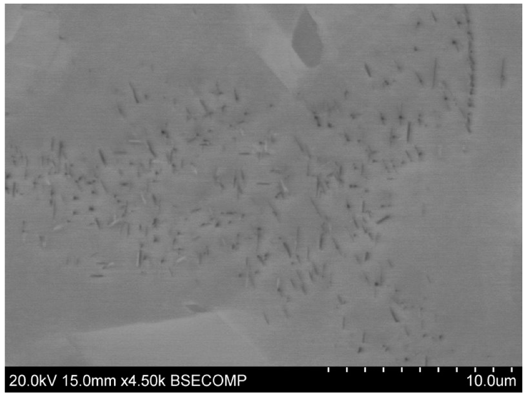
In the heat-affected zone towards the substrate, there is a higher ferrite content since the plate has the initial 2507 composition, and not an elevated Ni content. The ferrite has low solubility of nitrogen resulting in precipitation of Cr nitrides. Rod-like particles of Cr nitride are seen in the SEM micrograph in Figure 17. Due to the much lower ferrite volume fraction in the walls (usually <30%), Cr nitrides were not observed here.

4. Conclusions

The present investigation has emphasized WAAM of superduplex stainless steel in terms of building walls with different heat cycles to assess the susceptibility to form brittle intermetallic sigma and chi phases. The following conclusions are stated:
  • WAAM of superduplex stainless steels are feasible for industrial building or repair of components, but attention is needed to control the cooling rate to be sufficiently fast to prevent brittle intermetallic sigma phase from forming.
  • Welding with low heat input and low interpass temperature can be performed without any intermetallics present.
  • The ferrite content in HAZ in the support plate, primary and non-reheated region, was slightly reduced with increasing heat input and interpass temperature.
  • The ferrite content approached the lower acceptance level in the phase balance of ferrite–austenite of 25–60%.
  • The present results conflicts with the push towards more production efficiency and lower costs. High interpass temperature benefits productivity, but promotes sigma, and hence, severe deterioration of the toughness. A post weld solution heat treatment can be used to remove the intermetallic phases, but is costly and therefore not desirable.

Author Contributions

Conceptualization, O.M.A.; Investigation, O.M.A., R.B. and H.W.Å.; Writing—original draft preparation, O.M.A.; Writing—review and editing, O.M.A., R.B., H.W.Å., X.R. and B.N.; Project administration, X.R. All authors have read and agreed to the published version of the manuscript.

Funding

This research was funded by the Norwegian Research Council, grant number 281927. HWÅ acknowledges financial support from the NTNU Aluminium Product Innovation Center (NAPIC). RB acknowledges support from the Research Council of Norway through the Norwegian Center for Transmission Electron Microscopy, NORTEM (197405/F50).

Data Availability Statement

Data available on request.

Conflicts of Interest

The authors declare no conflict of interest.

References

  1. Martina, F.; Mehnen, J.; Williams, S.W.; Colegrove, P.; Wang, F. Investigation of the benefits of plasma deposition for the additive layer manufacture of Ti–6Al–4V. J. Mater. Process. Technol. 2012, 212, 1377–1386. [Google Scholar] [CrossRef] [Green Version]
  2. Szost, B.A.; Terzi, S.; Martina, F.; Boisselier, D.; Prytuliak, A.; Pirling, T.; Hofmann, M.; Jarvis, D.J. A comparative study of additive manufacturing techniques: Residual stress and microstructural analysis of CLAD and WAAM printed Ti–6Al–4V components. Mater. Des. 2016, 89, 559–567. [Google Scholar] [CrossRef] [Green Version]
  3. Williams, S.W.; Martina, F.; Addison, A.C.; Ding, J.; Pardal, G.; Colegrove, P. Wire plus Arc Additive Manufacturing. Mater. Sci. Technol. 2016, 32, 641–647. [Google Scholar] [CrossRef] [Green Version]
  4. Asala, G.; Khan, A.K.; Andersson, J.; Ojo, O.A. Microstructural Analyses of ATI 718Plus® Produced by Wire-ARC Additive Manufacturing Process. Metall. Mater. Trans. 2017, 48, 4211–4228. [Google Scholar] [CrossRef] [Green Version]
  5. Haden, C.V.; Zeng, G.; Carter, F.M.; Ruhl, C.; Krick, B.A.; Harlow, D.G. Wire and arc additive manufactured steel: Tensile and wear properties. Addit. Manuf. 2017, 16, 115–123. [Google Scholar] [CrossRef]
  6. Ji, L.; Lu, J.; Liu, C.; Jing, C.; Fan, H.; Ma, S. Microstructure and mechanical properties of 304L steel fabricated by arc additive manufacturing. In Proceedings of the 2017 International Conference on Electronic Information Technology and Computer Engineering (EITCE 2017), MATEC Web of Conferences 128, Singapore, 27–29 December 2017. [Google Scholar]
  7. Rodriguez, N.; Vázquez, L.; Huarte, I.; Arruti, E.; Tabernero, I.; Alvarez, P. Wire and arc additive manufacturing: A comparison between CMT and TopTIG processes applied to stainless steel. Weld. World 2018, 62, 1083–1096. [Google Scholar] [CrossRef]
  8. Martina, F.; Ding, J.; Williams, S.; Caballero, A.; Pardal, G.; Quintino, L. Tandem metal inert gas process for high productivity wire arc additive manufacturing in stainless steel. Addit. Manuf. 2019, 25, 545–550. [Google Scholar] [CrossRef] [Green Version]
  9. Caballero, A.; Ding, J.; Ganguly, S.; Williams, S. Wire + Arc Additive Manufacture of 17-4 PH stainless steel: Effect of different processing conditions on microstructure, hardness, and tensile strength. J. Mater. Process. Technol. 2018, 268, 54–62. [Google Scholar] [CrossRef]
  10. Eriksson, M.; Lervik, M.; Sørensen, C.; Robertstad, A.; Brønstad, B.M.; Nyhus, B.; Aune, R.; Ren, X.; Akselsen, O.M. Additive manufacture of superduplex stainless steel using WAAM. In Proceedings of the 5th International Conference of Engineering Against Failure, ICEAF-V 2018, MATEC Web of Conferences, Chios Island, Greece, 20–22 June 2018; Volume 188, p. 03014. [Google Scholar] [CrossRef]
  11. Ahn, Y.S.; Kang, J.P. Effect of aging treatments on microstructure and impact properties of tungsten substituted 2205 duplex stainless steel. Mater. Sci. Technol. 2000, 16, 382–388. [Google Scholar] [CrossRef]
  12. Chen, T.H.; Weng, K.L.; Yang, J.R. The effect of high-temperature exposure on the microstructural stability and toughness property in a 2205 duplex stainless steel. Mater. Sci. Eng. 2002, 338, 259–270. [Google Scholar] [CrossRef]
  13. El Koussy, M.R.; El Mahallawi, I.S.; Khalifa, W.; Al Dawood, M.M.; Bueckins, M. Effects of thermal aging on microstructure and mechanical properties of duplex stainless steel weldments. Mater. Sci. Technol. 2004, 20, 375–381. [Google Scholar] [CrossRef]
  14. Nilsson, J.O.; Wilson, A. Influence of isothermal phase transformations on toughness and pitting corrosion of super duplex stainless steel SAF 2507. Mater. Sci. Technol. 1993, 9, 545–554. [Google Scholar] [CrossRef]
  15. Kasper, J.S. The ordering of atoms in the chi-phase of the iron-chromium-molybdenum system. Acta Metall. 1954, 2, 456–461. [Google Scholar] [CrossRef]
  16. Ånes, H.W.; Natlandsmyr, O.; Bergh, T.; Lervik, L. pyxem/kikuchipy: Kikuchipy 0.4.0. 2021. Available online: https://zenodo.org/record/5082225#.Ybv5bmhBxPY (accessed on 12 December 2021).
  17. Callahan, P.G.; De Graef, M. Dynamical Electron Backscatter Diffraction Patterns. Part I: Pattern Simulations. Microsc. Microanal. 2013, 19, 1255–1265. [Google Scholar] [CrossRef] [PubMed]
  18. Singh, S.; De Graef, M. Orientation sampling for dictionary-based diffraction pattern indexing methods. Model. Simul. Mater. Sci. Eng. 2016, 24, 085013. [Google Scholar] [CrossRef]
  19. Lervåg, M.; Sørensen, C.; Robertstad, A.; Brønstad, B.M.; Nyhus, B.; Eriksson, M.; Aune, R.; Ren, X.; Akselsen, O.M.; Bunaziv, I. Additive manufacturing with superduplex stainless steel wire by CMT process. Metals 2020, 10, 272. [Google Scholar] [CrossRef] [Green Version]
  20. Fisher, R.M.; Dulls, E.J.; Carroll, K.G. Identification of the precipitate accompanying 885 °F embrittlement in chromium steels. Trans. AIME 1953, 197, 690–695. [Google Scholar]
  21. API (American Petroleum Institute). Use of Duplex Stainless Steels in the Oil Refining Industry, 2nd ed.; Technical Report 938-C; American Petroleum Institute (API): Washington, DC, USA, 2011. [Google Scholar]
  22. NACE—National Association for Corrosion. Engineers-ANSI/NACE MR0175/ISO 15156: Petroleum, Petrochemical, and Natural Gas Industries—Materials for Use in H2S-Containing Environments in Oil and Gas Production—General Principles for Selection of Cracking-Resistant Materials; National Association for Corrosion: Houston, TX, USA, 2015. [Google Scholar]
  23. Magnabosco, R. Kinetics of Sigma Phase Formation in a Duplex Staineless Steel. Mater. Res. 2009, 12, 321–327. [Google Scholar] [CrossRef] [Green Version]
  24. Nilsson, J.-O.; Karlsson, L.; Andersson, J.O. Secondary austenite formation and its relation to pitting corrosion in duplex stainless steel weld metal. Mater. Sci. Technol. 1995, 11, 276–283. [Google Scholar] [CrossRef]
  25. Ottonello, G.; Borketa, M.; Sciuto, P.F. Parameterization of energy and interactions in garnets: End-member Properties. Am. Mineral. 1996, 81, 429–447. [Google Scholar] [CrossRef]
  26. Atamert, S.; King, J.E. Sigma-phase formation and its prevention in duplex stainless steels. J. Mater. Sci. Lett. 1993, 12, 1144–1147. [Google Scholar] [CrossRef]
  27. Nilsson, J.O. Superduplex stainless steels. Mater. Sci. Technol. 1992, 8, 685–700. [Google Scholar] [CrossRef]
  28. Sato, Y.S.; Kokawa, H. Preferential precipitation site of sigma phase in duplex stainless steel weld metal. Scr. Mater. 1999, 40, 659–663. [Google Scholar] [CrossRef]
Figure 1. Microstructure of the building plate (austenite is white, ferrite is brownish).
Metals 11 02045 g001
Figure 2. (a) Macrographs of walls (cross sections). (b) Schematic illustration of the walls with the Charpy and crack tip opening displacement (CTOD) specimens indicated.
Metals 11 02045 g002
Figure 3. Hardness in different regions. Error bars indicate standard deviation.
Metals 11 02045 g003
Figure 4. Charpy V results; tested at −46 °C. Data for −20 °C taken from Lervåg et al. [19]. (a) Effect of mean heat input, and (b) effect of mean interpass temperature. The results from the present study are compared with previous data for superduplex steels, indicating that there is a certain temperature effect; the previous results are from testing at −20 °C while the current walls are tested at −46 °C. The previously published data by Lervåg et al. [19] illustrate that the toughness of the walls is nearly independent of the gross arc energy due to limited microstructure variations; the Charpy values are all close to 100 J. However, it is reasonable to assume that the major reason for the toughness fall is due to σ formation, especially for the 0.63 kJ/mm heat input combined with high interpass temperature.
Metals 11 02045 g004
Figure 5. CTOD fracture toughness; tested at −46 °C. Data for −20 °C taken from Lervåg et al. [19]. (a) Effect of mean heat input, and (b) effect of mean interpass temperature (left).
Metals 11 02045 g005
Figure 6. Epitaxial solidification in Wall 1.
Metals 11 02045 g006
Figure 7. Microstructure of primary (non-reheated) region, next last layer of Wall 1.
Metals 11 02045 g007
Figure 8. Reheated layer microstructure of Wall 1.
Metals 11 02045 g008
Figure 9. Ferrite content in different wall regions. Error bars indicate standard deviation.
Metals 11 02045 g009
Figure 10. HAZ microstructure.
Metals 11 02045 g010
Figure 11. Sigma phase content as a function of mean interpass temperature. The black curve is an exponential fit.
Metals 11 02045 g011
Figure 12. EBSD phase maps from Wall 1; ferrite is green, austenite is red.
Metals 11 02045 g012
Figure 13. EBSD phase maps from Wall 1 showing the presence of secondary austenite. Ferrite is green, austenite is red. (b) is close-up of square in (a). Arrows point to γ2.
Metals 11 02045 g013
Figure 14. Sigma phase in Wall 3; (a) Backscattered electron (BSE) image showing the microstructure (Sigma is white), (b) EDX maps of Fe, Cr, Ni, and Mo.
Metals 11 02045 g014aMetals 11 02045 g014b
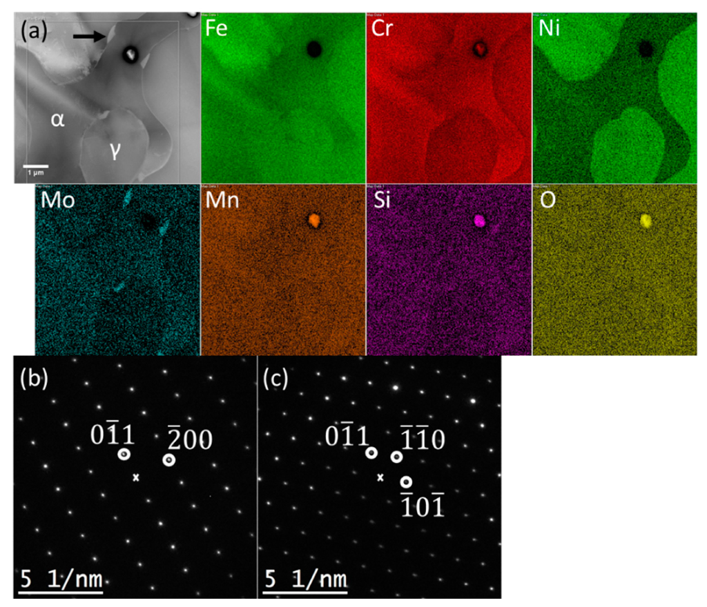
Figure 15. EBSD phase map showing an area from Wall 3 with significant amounts of sigma phase. The center column shows four experimental patterns taken from the positions indicated in Table 3. sample (Figure 16) also revealed the presence of the chi phase, which has a similar composition to the sigma phase. However, the fact that this phase was not found in the SEM investigation suggests that this phase is present in much lower quantities than the sigma phase.
Metals 11 02045 g015
Figure 16. (a) HAADF STEM image and corresponding EDX maps from an area of Wall 3 with several particles. The Mo-rich particles were identified as the bcc chi phase. The oxide particle might be of the bcc Mn3Cr2(SiO4)3 phase (Ottonello, 1996 [25]). (b) Diffraction pattern from the [011] zone axis of the chi particle pointed to by a black arrow in (a). The Miller indices of the circled reflections are indicated. (c) Diffraction pattern from the same chi particle near the [-111] zone axis, tilted 35° from (b).
Metals 11 02045 g016
Figure 17. SEM image of Cr nitrides in HAZ of building plate.
Metals 11 02045 g017
Table 1. Chemical composition of selected welding wire and building plate (in weight%).
MaterialCSiMnPSCrNiMoCuNW
Wire0.0180.30.70.020.00125.09.53.70.60.230.6
Plate0.0200.320.850.0230.000324.86.63.70.160.26-
Table 2. Layer deposition parameters.
ParameterWeld No
W1W2W3
Average current (A)197161202
Average voltage (V)212022
Travel speed (mm/s)7.07.07.0
Wire feed rate (mm/s)7.75.88.2
Heat input (kJ/mm)0.590.460.63
Average interpass temperature (°C)85152359
Average interpass time (s)36012040
PolarityDC+DC+DC+
Table 3. Deposition results.
Wall Production DataWeld No
W1W2W3
Number of layers171616
Average layer height (mm)2.62.02.1
Wall width (mm)11.69.28.9
Wall length (mm)230230230
Deposition time (min)90.515.936.5
Publisher’s Note: MDPI stays neutral with regard to jurisdictional claims in published maps and institutional affiliations.