Effect of Tempering Temperature on Microstructure and Mechanical Properties of Bainitic Railway Wheel Steel with Thermal Damage Resistance by Alloy Design


Abstract
:1. Introduction
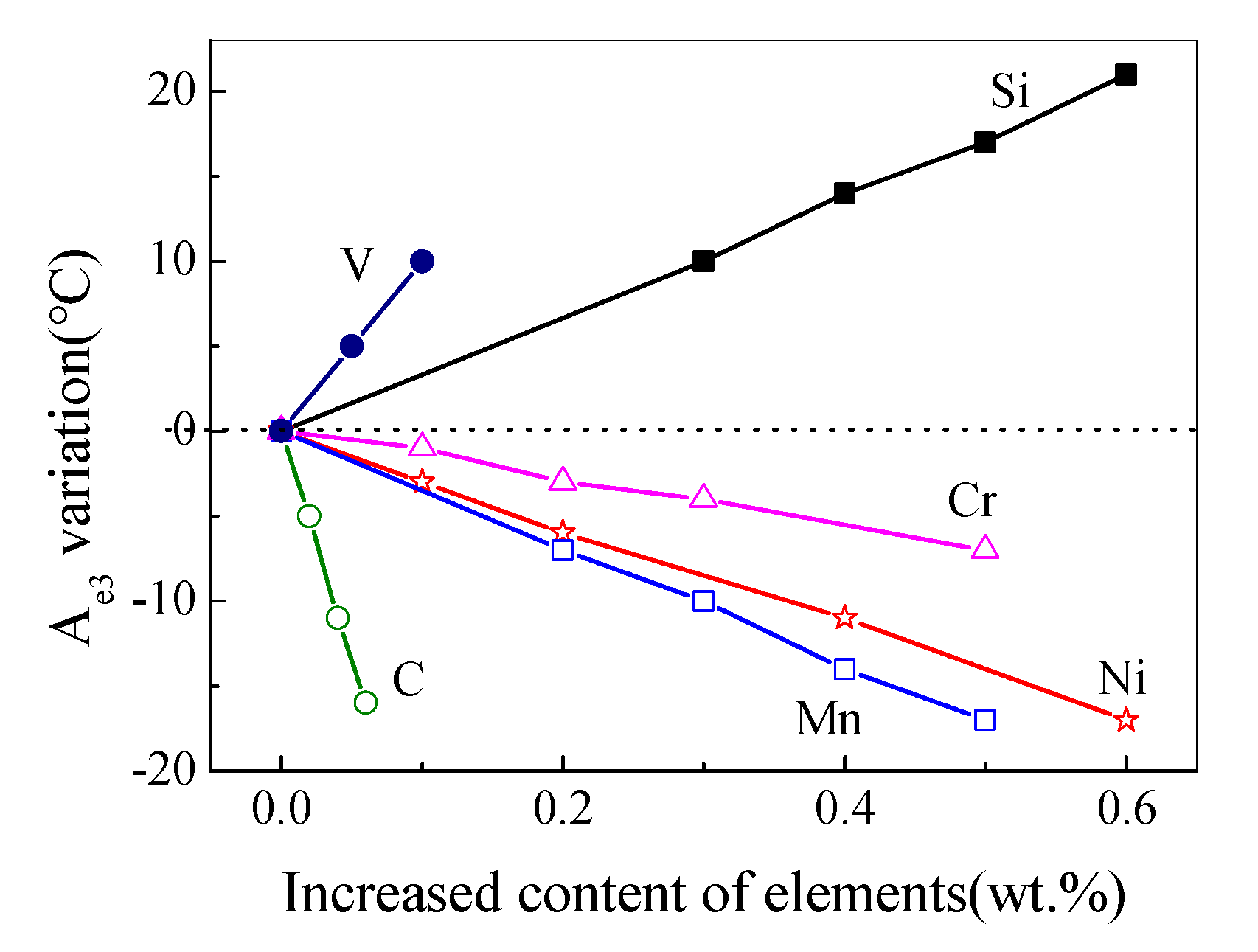
2. Alloy Design
3. Experimental
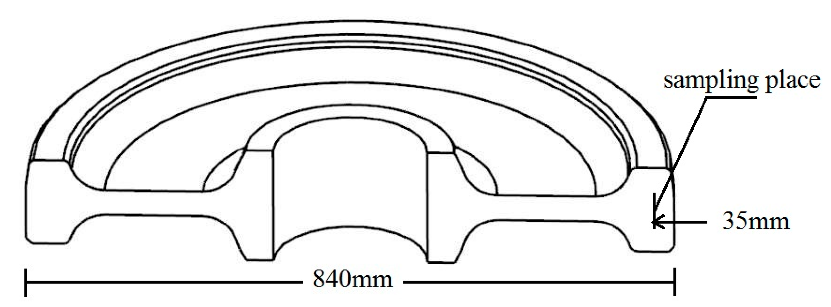
3.1. Treatment
3.2. Microstructure Characterization
3.3. Mechanical Properties
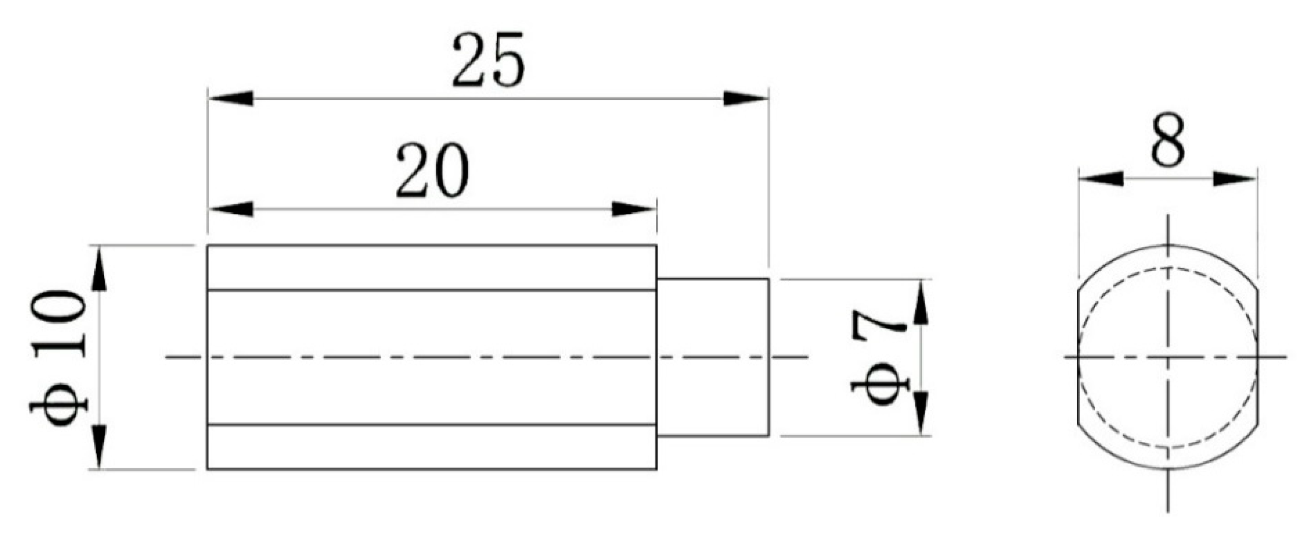
3.4. Thermal Damage Resistance
4. Results and Discussion
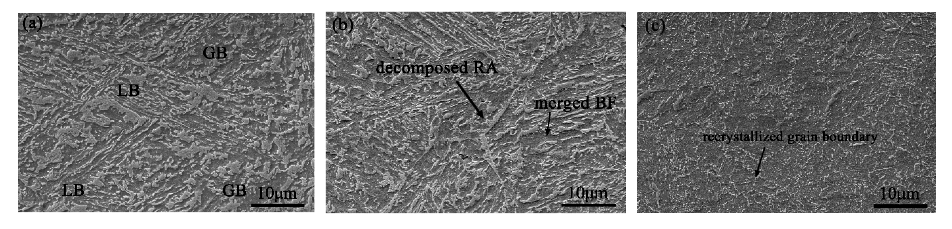
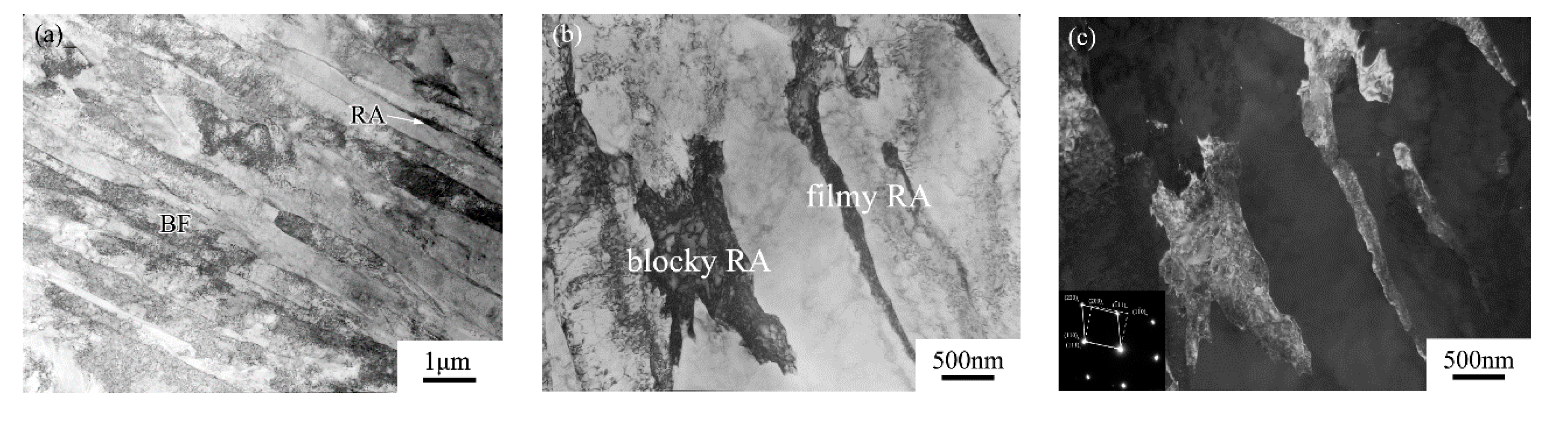
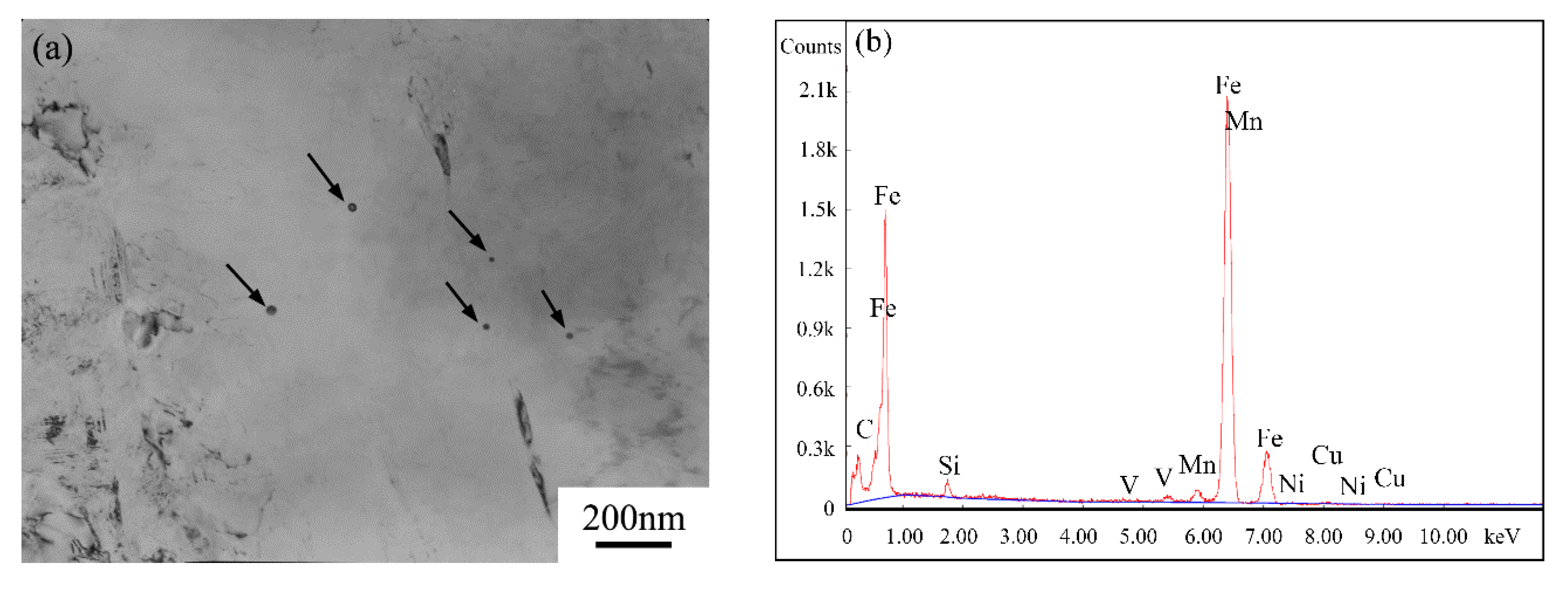
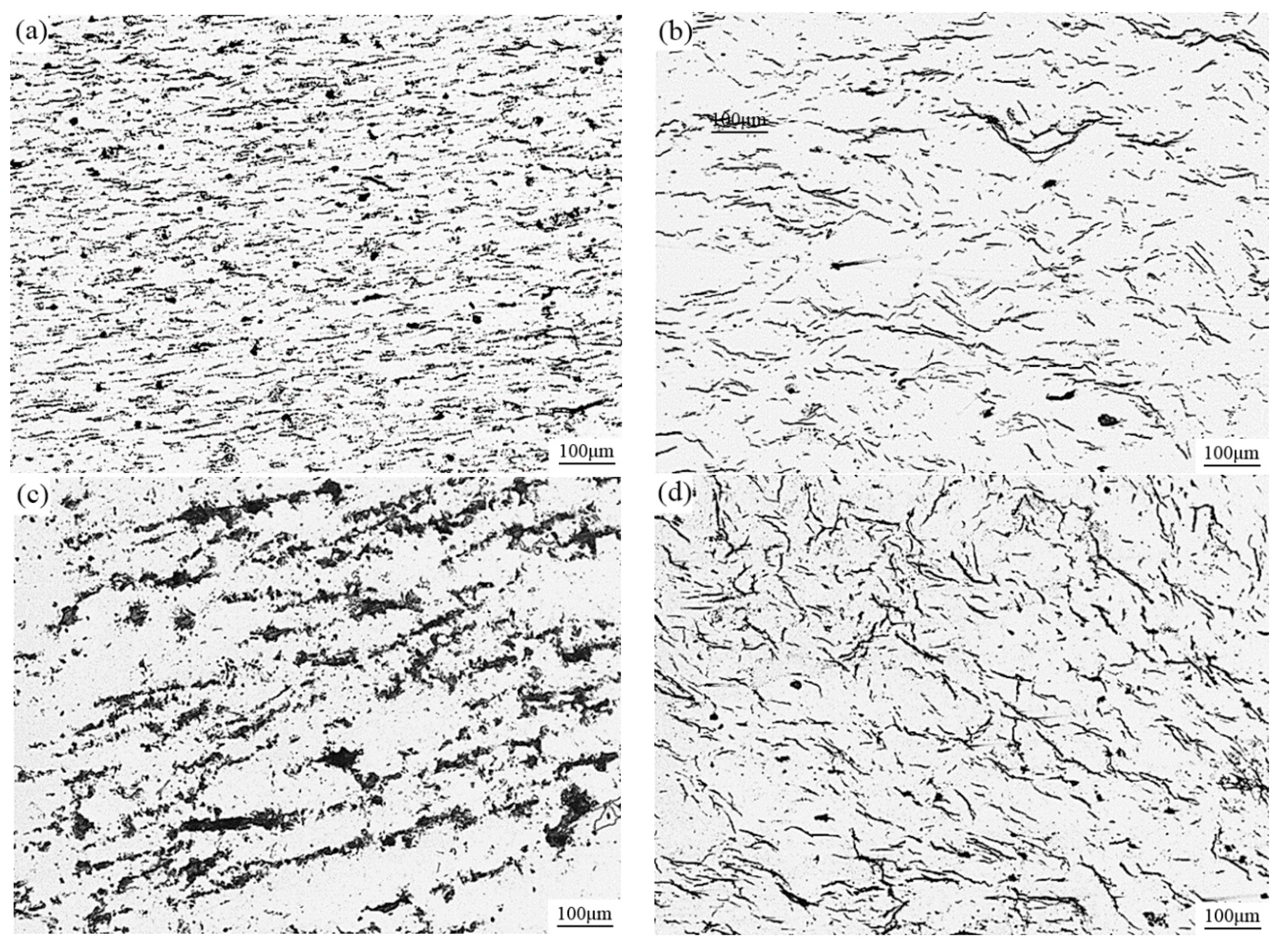
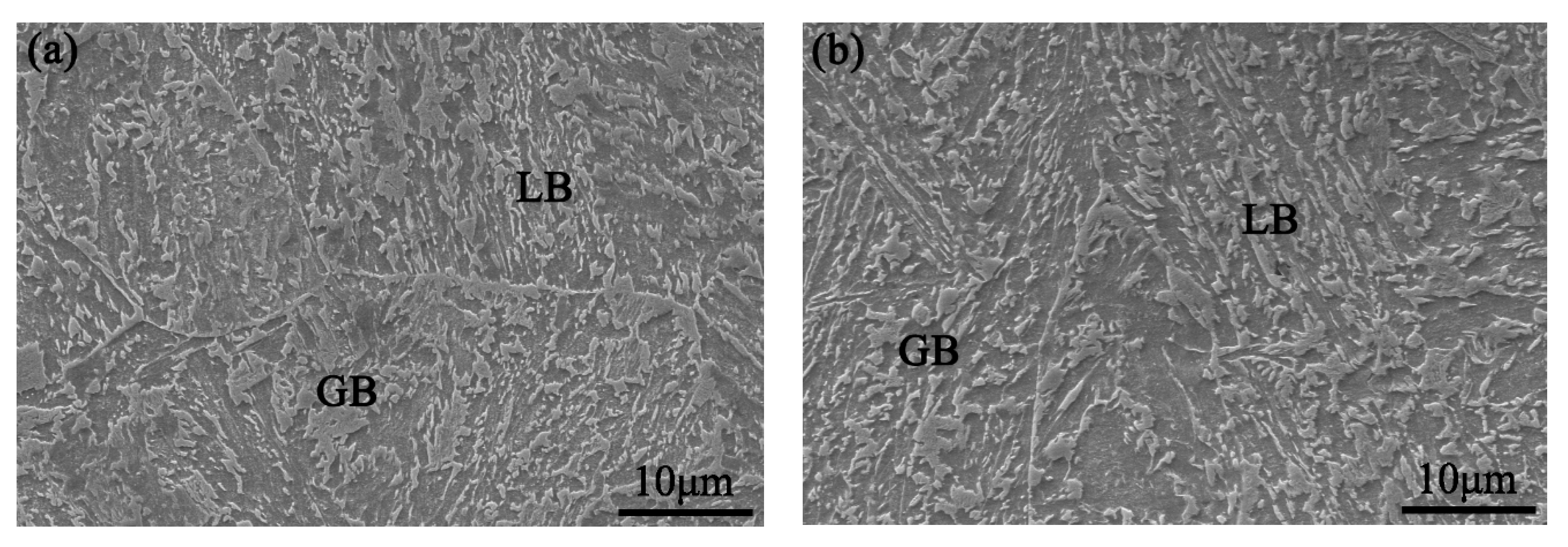
4.1. Microstructure
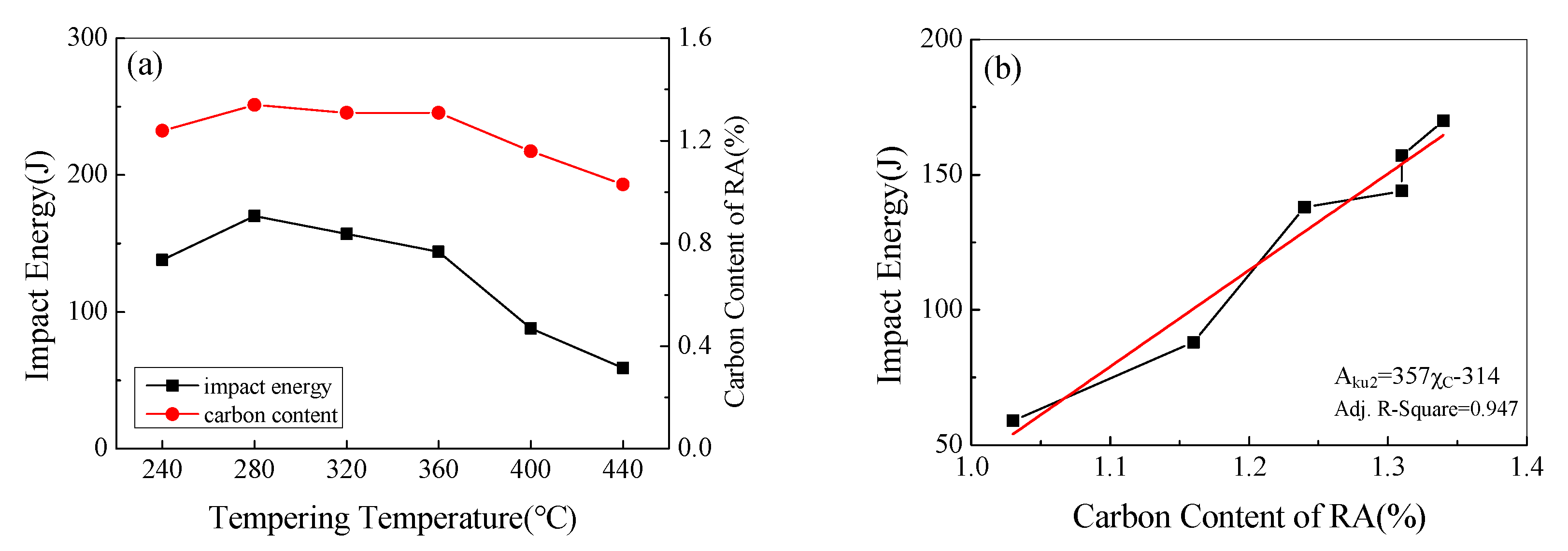
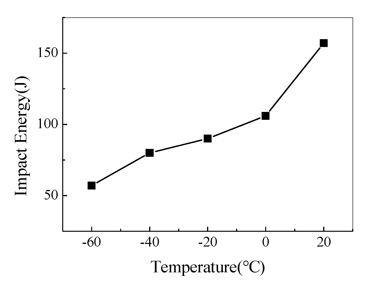
4.2. Mechanical Properties
4.3. Thermal Damage Resistance
5. Conclusions
- The new bainitic wheel steel achieved excellent integrated mechanical properties at the tempering temperature range of 280–360 °C.
- The tested steel has a two-time-strengthening mechanism of yield strength at 280–360 °C and 480–560 °C, respectively. The latter one is led by fine V(C,N) precipitation.
- This new bainitic wheel steel shows a much higher match of strength and toughness at a proper tempered state than commercial pearlitic railway wheel steel Cl70, especially more excellent low temperature toughness.
- The V bearing bainitic wheel steel has better thermal damage resistance than the commercial pearlitic wheel.
Author Contributions
Funding
Conflicts of Interest
References
- Sharma, S.; Sangal, S.; Mondal, K. Wear behavior of newly developed bainitic wheel steels. J. Mater. Eng. Perform. 2014, 24, 999–1010. [Google Scholar] [CrossRef]
- Zeng, D.; Lu, L.; Gong, Y.; Zhang, N.; Gong, Y. Optimization of strength and toughness of railway wheel steel by alloy design. Mater. Des. 2016, 92, 998–1006. [Google Scholar] [CrossRef]
- Su, H.; Pan, T.; Li, L.; Yang, C.F.; Cui, Y.H.; Ji, H.Z. Frictional heat-induced phase transformation on train wheel surface. J. Iron Steel Res. Int. 2008, 15, 49–55. [Google Scholar] [CrossRef]
- Zhang, M.R.; Gu, H.C. Microstructure and properties of carbide free bainite railway wheels produced by programmed quenching. Mater. Sci. Technol. 2013, 23, 970–974. [Google Scholar] [CrossRef]
- Kapito, A.; Stumpf, W.; Papo, M.J. On the development of bainitic alloys for railway wheel applications. J. S. Afr. Inst. Min. Met. 2012, 112, 539–544. [Google Scholar]
- Ahlström, J.; Karlsson, B. Modelling of heat conduction and phase transformations during sliding of railway wheels. Wear 2002, 253, 291–300. [Google Scholar] [CrossRef]
- Huai zhong, J.I.; Hang, S.U.; Yang, C.F.; Zhang, Y.Q. Friction heat induced phase transformation and spalling mechanism of train wheel steel. J. Iron Steel Res. 2005, 17, 55–59. [Google Scholar]
- Long, X.Y.; Kang, J.; Lv, B.; Zhang, F.C. Carbide-free bainite in medium carbon steel. Mater. Des. 2014, 64, 237–245. [Google Scholar] [CrossRef]
- Leiro, A.; Roshan, A.; Sundin, K.G.; Vuorinen, E.; Prakash, B. Fatigue of 0.55C–1.72Si steel with tempered martensitic and carbide-free bainitic microstructures. Acta Metall. Sin. Engl. Lett. 2014, 27, 55–62. [Google Scholar] [CrossRef]
- Graux, A.; Cazottes, S.; Castro, D.D.; San-Martín, D.; Capdevila, C.; Cabrera, J.M.; Molas, S.; Schreiber, S.; Mirković, D.; Danoix, F.; et al. Design and development of complex phase steels with improved combination of strength and stretch-flangeability. Metals 2020, 10, 824. [Google Scholar] [CrossRef]
- Podgornik, B.; Brunčko, M.; Kirbiš, P. Wear resistance of high c high si steel with low retained austenite content and kinetically activated bainite. Metals 2020, 10, 672. [Google Scholar] [CrossRef]
- Pushkareva, I.; Shalchi-Amirkhiz, B.; Allain, S.Y.P.; Geandier, G.; Fazeli, F.; Sztanko, M.; Scott, C. The influence of vanadium additions on isothermally formed bainite microstructures in medium carbon steels containing retained austenite. Metals 2020, 10, 392. [Google Scholar] [CrossRef] [Green Version]
- Santacruz-Londoño, A.F.; Rios-Diez, O.; Jiménez, J.A.; Garcia-Mateo, C.; Aristizábal-Sierra, R. Microstructural and mechanical characterization of a nanostructured bainitic cast steel. Metals 2020, 10, 612. [Google Scholar] [CrossRef]
- Tian, Y.; Tan, Z.L.; Li, J.; Gao, B.; Zhang, M.; Bai, B.Z. Low temperature deformation induced microstructure refinement and consequent ultrahigh toughness of a 20Mn2SiCrNi bainitic steel. Metals 2020, 10, 19. [Google Scholar] [CrossRef] [Green Version]
- Wang, K.; Tan, Z.; Gao, G.; Gui, X.; Misra, R.D.; Bai, B. Ultrahigh strength-toughness combination in bainitic rail steel: The determining role of austenite stability during tempering. Mater. Sci. Eng. A 2016, 662, 162–168. [Google Scholar] [CrossRef]
- Zhang, M.; Qian, J.; Gu, H. The structure stability of carbide-free bainite wheel steel. J. Mater. Eng. Perform. 2007, 16, 635–639. [Google Scholar] [CrossRef]
- Zhang, M.R.; Gu, H.C. Fracture toughness of nanostructured railway wheels. Eng. Fract. Mech. 2008, 75, 5113–5121. [Google Scholar] [CrossRef]
- Liu, D.; Bai, B.; Fang, H.; Zhang, W.; Gu, J.; Chang, K. Effect of tempering temperature and carbide free bainite on the mechanical characteristics of a high strength low alloy steel. Mater. Sci. Eng. A 2004, 371, 40–44. [Google Scholar] [CrossRef]
- Guo, A.; Song, X.; Tang, J.; Yuan, Z. Effect of tempering temperature on the mechanical properties and microstructure of an copper-bearing low carbon bainitic steel. J. Univ. Sci. Technol. Beijing 2008, 15, 38–42. [Google Scholar] [CrossRef]
- Yi, L.; Peng, J.M.; Wang, H.B.; Wu, X.C. Effect of tempering on microstructure and mechanical properties of a non-quenched bainitic steel. Mater. Sci. Eng. A 2010, 527, 3433–3437. [Google Scholar]
- Kang, J.; Zhang, F.C.; Yang, X.W.; Lv, B.; Wu, K.M. Effect of tempering on the microstructure and mechanical properties of a medium carbon bainitic steel. Mater. Sci. Eng. A 2017, 686, 150–159. [Google Scholar] [CrossRef]
- De Cooman, B.C. Structure-properties relationship in trip steels containing carbide-free bainite. Curr. Opin. Solid State Mater. Sci. 2004, 8, 285–303. [Google Scholar] [CrossRef]
- Mesquita, R.A.; Kestenbach, H.J. On the effect of silicon on toughness in recent high quality hot work steels. Mater. Sci. Eng. A 2011, 528, 4856–4859. [Google Scholar] [CrossRef]
- Qiu, J.A.; Wu, K.M.; Li, J.H.; Hodgson, P.D.; Hou, T.P.; Ding, Q.F. Effect of silicon on ultra-low temperature toughness of nb-ti microalloyed cryogenic pressure vessel steels. Mater. Charact. 2013, 83, 123–128. [Google Scholar] [CrossRef]
- Kozeschnik, E.; Bhadeshia, H.K.D.H. Influence of silicon on cementite precipitation in steels. Mater. Sci. Technol. 2013, 24, 343–347. [Google Scholar] [CrossRef]
- Hofer, C.; Leitner, H.; Winkelhofer, F.; Clemens, H.; Primig, S. Structural characterization of “carbide-free” bainite in a Fe–0.2C–1.5Si–2.5Mn steel. Mater. Charact. 2015, 102, 85–91. [Google Scholar] [CrossRef]
- Keehan, E.; Karlsson, L.; Andrén, H.O.; Bhadeshia, H.K.D.H. Influence of carbon, manganese and nickel on microstructure and properties of strong steel weld metals: Part 2—Impact toughness gain resulting from manganese reductions. Sci. Technol. Weld. Join. 2013, 11, 9–18. [Google Scholar] [CrossRef]
- Chen, Y.L.; Dong, C.Z.; Cai, Q.W.; Wan, D.C.; Liang, L.I.; Yue, Q.I. Effect of mo and ni on microstructure and mechanical properties of carbide-free bainite ultra-high strength steels. J. Mater. Eng. 2013, 3, 16–21. [Google Scholar]
- Chen, J.; Xing, X.; Wang, Y.; Zhou, Y.; Ren, X.; Yang, Y.; Yang, Q. Effects of vanadium addition on microstructure and tribological performance of bainite hardfacing coatings. J. Mater. Eng. Perform. 2015, 24, 1157–1164. [Google Scholar] [CrossRef] [Green Version]
- Kim, K.-S.; Du, L.-X.; Gao, C.-R. Influence of vanadium content on bainitic transformation of a low-carbon boron steel during continuous cooling. Acta Metall. Sin. (Engl. Lett.) 2015, 28, 692–698. [Google Scholar] [CrossRef] [Green Version]
- Karmakar, A.; Mukherjee, S.; Kundu, S.; Srivastava, D.; Mitra, R.; Chakrabarti, D. Effect of composition and isothermal holding temperature on the precipitation hardening in vanadium-microalloyed steels. Mater. Charact. 2017, 132, 31–40. [Google Scholar] [CrossRef]
- Wang, K.K.; Tan, Z.L.; Gu, K.X.; Gao, B.; Gao, G.H.; Misra, R.D.K.; Bai, B.Z. Effect of deep cryogenic treatment on structure-property relationship in an ultrahigh strength Mn–Si–Cr bainite/martensite multiphase rail steel. Mat. Sci. Eng. A 2017, 684, 559–566. [Google Scholar] [CrossRef]
- Kumar, A.; Dutta, A.; Makineni, S.K.; Herbig, M.; Petrov, R.H.; Sietsma, J. In-situ observation of strain partitioning and damage development in continuously cooled carbide-free bainitic steels using micro digital image correlation. Mat. Sci. Eng. A 2019, 757, 107–116. [Google Scholar] [CrossRef]
- Mao, X.P.; Huo, X.D.; Sun, X.J.; Chai, Y.Z. Strengthening mechanisms of a new 700 MPa hot rolled Ti-microalloyed steel produced by compact strip production. J. Mater. Process. Technol. 2010, 210, 1660–1666. [Google Scholar] [CrossRef]
- Han, S.Y.; Shin, S.Y.; Seo, C.-H.; Lee, H.; Bae, J.-H.; Kim, K.; Lee, S.; Kim, N.J. Effects of Mo, Cr, and V additions on tensile and Charpy impact properties of API X80 pipeline steels. Metall. Mater. Trans. A 2009, 40, 1851–1862. [Google Scholar] [CrossRef] [Green Version]
- Donzella, G.; Scepi, M.; Solazzi, L.; Trombini, F. The effect of block braking on the residual stress state of a solid railway wheel. Proc. Inst. Mech. Eng. Part F J. Rail Rapid Transit 1998, 212, 145–158. [Google Scholar] [CrossRef]
- Hamada, S.; Sakoda, Y.; Sasaki, D.; Ueda, M.; Noguchi, H. Evaluation of fatigue limit characteristics of lamellar pearlitic steel in consideration of microstructure. J. Soc. Mater. Sci. Jpn. 2011, 60, 790–795. [Google Scholar] [CrossRef]
- Zhao, P.; Cheng, C.; Gao, G.; Hui, W.; Misra, R.D.K.; Bai, B.; Weng, Y. The potential significance of microalloying with niobium in governing very high cycle fatigue behavior of bainite/martensite multiphase steels. Mat. Sci. Eng. A 2016, 650, 438–444. [Google Scholar] [CrossRef]


| C | Mn | Si + Mo | Ni | V | P | S | Fe |
|---|---|---|---|---|---|---|---|
| 0.22 | 2.2 | 1.5~2.2 | 0.4 | 0.1 | 0.010 | 0.006 | Bal. |
| Tempering Temperature/°C | Volume of Retained Austenite/% | Carbon content of Retained Austenite/% | Ms of Retained Austenite/°C |
|---|---|---|---|
| As-quenched | 13.7 | 1.06 | 20 |
| 240 | 8.3 | 1.24 | −56 |
| 280 | 6.6 | 1.34 | −99 |
| 320 | 7.6 | 1.31 | −86 |
| 360 | 6.4 | 1.31 | −86 |
| 400 | 7.7 | 1.16 | −23 |
| 440 | 2.5 | 1.03 | 32 |
| Tempering Temperature/°C | Tensile Strength/MPa | Yield Strength/Mpa | Elongation to fracture/% | Hardness HRC | Impact Energy/J |
|---|---|---|---|---|---|
| 240 | 1072 | 794 | 18.5 | 34 | 138 |
| 280 | 1050 | 814 | 18 | 32 | 170 |
| 320 | 1055 | 837 | 19 | 33 | 157 |
| 360 | 1051 | 843 | 19 | 35 | 144 |
| 400 | 1054 | 827 | 20 | 34 | 88 |
| 440 | 1090 | 754 | 17 | 33 | 59 |
| 480 | 1075 | 793 | 17 | 34 | 51 |
| 560 | 1047 | 858 | 19 | 33 | 53 |
| 640 | 921 | 786 | 21 | 28 | 80 |
| Microstructure Pattern of Wheel Steel | Tensile Strength/MPa | Yield Strength/Mpa | Elongation to Fracture/% | Hardness HRC | Impact Energy/J |
|---|---|---|---|---|---|
| CFB | 1055 | 837 | 19 | 33 | 157 |
| Pearlitic (CL70) | 1190 | 761 | 16 | 28 | 26 |
© 2020 by the authors. Licensee MDPI, Basel, Switzerland. This article is an open access article distributed under the terms and conditions of the Creative Commons Attribution (CC BY) license (http://creativecommons.org/licenses/by/4.0/).
Share and Cite
Zhu, J.; Tan, Z.; Tian, Y.; Gao, B.; Zhang, M.; Wang, J.; Weng, Y. Effect of Tempering Temperature on Microstructure and Mechanical Properties of Bainitic Railway Wheel Steel with Thermal Damage Resistance by Alloy Design. Metals 2020, 10, 1221. https://doi.org/10.3390/met10091221
Zhu J, Tan Z, Tian Y, Gao B, Zhang M, Wang J, Weng Y. Effect of Tempering Temperature on Microstructure and Mechanical Properties of Bainitic Railway Wheel Steel with Thermal Damage Resistance by Alloy Design. Metals. 2020; 10(9):1221. https://doi.org/10.3390/met10091221
Chicago/Turabian StyleZhu, Jiaqi, Zhunli Tan, Yu Tian, Bo Gao, Min Zhang, Junxiang Wang, and Yuqing Weng. 2020. "Effect of Tempering Temperature on Microstructure and Mechanical Properties of Bainitic Railway Wheel Steel with Thermal Damage Resistance by Alloy Design" Metals 10, no. 9: 1221. https://doi.org/10.3390/met10091221