Review

Recent Advances in Very High Cycle Fatigue Behavior of Metals and Alloys—A Review

1
Department of Materials Science and Engineering, Ajou University, Suwon 16499, Korea
2
Department of Energy Systems Research, Ajou University, Suwon 16499, Korea
3
Metal Forming Technology R&D Group, Korea Institute of Industrial Technology, Incheon 21999, Korea
*
Author to whom correspondence should be addressed.
Metals 2020, 10(9), 1200; https://doi.org/10.3390/met10091200
Submission received: 14 August 2020 / Revised: 30 August 2020 / Accepted: 2 September 2020 / Published: 8 September 2020
(This article belongs to the Special Issue Fracture Mechanics and Fatigue Design in Metallic Materials)

Abstract

:
We reviewed the research and developments in the field of fatigue failure, focusing on very-high cycle fatigue (VHCF) of metals, alloys, and steels. We also discussed ultrasonic fatigue testing, historical relevance, major testing principles, and equipment. The VHCF behavior of Al, Mg, Ni, Ti, and various types of steels were analyzed. Furthermore, we highlighted the major defects, crack initiation sites, fatigue models, and simulation studies to understand the crack development in VHCF regimes. Finally, we reviewed the details regarding various issues and challenges in the field of VHCF for engineering metals and identified future directions in this area.

1. Introduction

1.1. History of Fatigue/Background
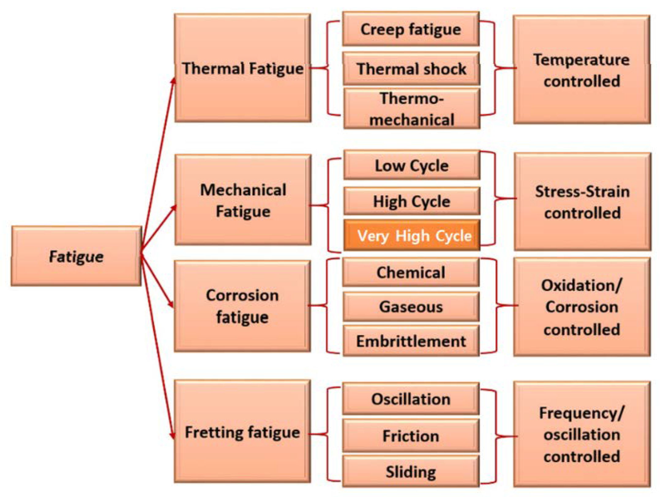
Preliminary observations were recorded at the beginning of the 19th century during the industrial revolution in Europe. During this time, several railways, heavy-duty locomotives, and engines accidentally failed after a long period of time. In 1829, W.A.S. Albert noticed this failure while performing cyclic loading on iron chain [1,2]. Later, in 1837, he reported a relation between cyclic load and lifespan of metal in a magazine. Following this observation, a cast-iron axle designer, J.V. Poncelet, used the term “fatigare” and F. Brainthwaite in Great Britain coined it as fatigue in 1854 [3,4].
In 1842, one of the worst rail disasters happened near Versailles, France. Several locomotives’ axles broke on the way. After inspection by W.J.M. Rankine from British railways, a brittle fracture in the axle was confirmed [2]. Following this observation, some pioneering work performed by August Wöhler on the failure of locomotive axles built the foundation of fatigue understanding. Wöhler plotted the Krupp axle steel data with respect to stress (S) and number of cycles to failure (N). This plot was later named the S-N diagram [5,6]. The S-N diagram is useful for forecasting the fatigue life and endurance limit of metals, i.e., the limiting threshold value of stress below which an engineering material exhibits a high or infinite high fatigue life. Thus, A. Wöhler is regarded as the grandfather of modern fatigue technology [7].
In 1886, J. Bauschinger published the first investigation on the stress-strain behavior of materials under cyclic loading. At the end of the 19th century, Gerber and Goodman performed systematic parametric investigations and proposed simplified fatigue theories. In 1910, O.H. Basquin further proposed the shape of the S-N diagram by applying Wöhler’s data on a log–log scale. Following various investigations, fracture mechanics was born via the crack propagation theory of A.A. Griffith in 1920 [8]. Various Manson-Coffin-Basquin (MCB) models and Langer models came into focus to study the strain characteristics which depend upon time. The MCB model was developed for tension-compression fatigue [9,10]. Later, the MCB model was replaced with Langer and Kandil and another model developed by Kurek and Lagoda under multiaxial loading [11,12,13]. Other fatigue investigations related to full-range fatigue regimes for more than 108 cycles (Kohout-Vechet model) were also pioneered including multi-fatigue damage parameters by recent researchers [14,15,16].
In practice, fatigue takes place under dynamic loading after a substantial period of service, in windmills, high-speed aircraft, ships, submarines, turbine blades, offshore platforms, launch vehicles, pressure vessels, etc. Most of the load-bearing applications in vehicles, engine parts, are loaded with 108 cycles, while railway components, bridges and wheels are loaded with 109 cycles in their lifetime. Therefore, there is a need for knowledge of fatigue behavior and safe operation limits in the VHCF regime. In the VHCF regime, the fatigue behavior is different compared to conventional high cycle fatigue. For instance, the fatigue behavior of high-strength steels in the VHCF regime show crack initiation at the inclusion site, while in high cycle fatigue (HCF), cracks are loacated preferentially at the surface [17,18]. Aluminium alloys have no fatigue limit but show slip band formation in VHCF regime [19,20]. There is no failure in Ti6Al4V at low stress ratios while the fatigue strength decreases at high stress ratios in VHCF [21,22,23,24]. It can be seen that VHCF behavior can be extrapolated from HCF data. The various distinct differences in VHCF and HCF have been reviewed by Li et al. [25]. VHCF mechanisms involving crack initiation at inclusion sites or other damage in the VHCF regime for defect free materials were reviewed by Zimmermann et al. [26]. In recent decades, the fatigue behavior of materials in VHCF regime has increased. However, the prominent cause of fatigue failure is still not clear and needs to be overviewed in detail. Therefore, this work focuses on the VHCF behavior of metals, alloys and steels. We also highlight the HCF fatigue behavior of novel high-entropy alloy systems for future guidance in extrapolating it to VHCF regime.

1.2. Classification

The word “fatigue” originated from the Latin word “fatigare” meaning “to tire”. This means that materials fail sooner than expected after tiring under cyclic loading [3]. Fatigue is the most vital criteria for designing engineering materials. The severity of damage can be understood by the fact that fatigue occurs more often at lower stresses than at the yielding of materials [27]. Fatigue life depends on the number of cycles a material can withstand before fracture. The fracture can occur in a few cycles, or sometimes it takes a large number of cycles before fracture. However, before going further, we classify various fatigue processes occurring in engineering materials, as shown in Figure 1.
There are different types of fatigue failures according to the types of loading and conditions. Based on the fatigue life cycle, it can be divided according to the number of cycles needed to reach failure, such as (1) low cycle fatigue (LCF) (~104 … ~105 cycles) and (2) high cycle fatigue (HCF) (~105 to 107 cycles). Additionally, fatigue life with more than 107 cycles is known as very-high cycle fatigue (VHCF) [28,29]. The fatigue crack initiation life is defined by the number of cycles required from the time of initiating a surface imperfection or grain size crack to the time of formation of a not-considerable length of crack. In other words, this is the number of cycles of fatigue crack propagation required for a microcrack to grow up to an easily definable length, 0.5 or 1 mm in length, while the number of cycles required to cause the failure of the material is the fatigue propagation life. The fatigue life is the sum of the fatigue crack initiation and propagation lives [30,31]. In this review, we mainly discuss VHCF.
Fatigue failure depends on other factors besides cyclic loads and temperature; these include the oxidizing environment, embrittlement, structural deformation, strain rate, and frequency of applied load. Various studies in the past have been devoted to LCF of engineering materials and the effect of temperature on fatigue life. The studies showed that fatigue life also depends on other factors such as strain rate, creep, oxidizing atmosphere, fretting cycle, frequency, and microstructural defects [30,31,32,33,34,35]. In fatigue failure, the dominating factor to damage is vague; hence, understanding of the failure mechanism is elusive.

1.3. Fatigue Testing Parameters

In fatigue testing, the load cycle is characterized by various parameters such as load ratio R (σminmax), stress amplitude σa, mean stress σm, and stress range ∆σ. Fatigue is evaluated in terms of fatigue strength and fatigue limit. Fatigue strength is the value of stress at which failure occurs after Nf cycles, while fatigue limit shows the limiting value of stress (Sf) at which failure occurs, as Nf becomes very large [27]. Fluctuating stresses can be classified into various categories. Commonly encountered stresses are tension-tension, compression-compression, pulsating, sinusoidal, irregular, or random stress cycles [8].
The fatigue data are generally represented by the stress (σ) versus the log number of cycles to failure (N). The S-N diagram is described for the value of the σm, or R (=−1), as shown in Figure 2. For Al alloys, there is no well-defined stress region below which these alloys fail. Therefore, the endurance limit is defined as the stress below which no failure occurs even for a large number of cycles (Nf), a measure of non-ferrous alloys [36].
The S-N diagram is employed to determine the number of cycles at a particular stress level before a fracture occurs [36]. It allows the engineers to design an alloy for the desired service life span, as shown in Figure 2a. Figure 2b presents the S-N diagram of various metals and alloys. We can see that mostly steels and titanium exhibit fatigue limit compared to ductile metals like Al or Cu. These diagrams only predict the fatigue limit of metals without any prior knowledge of cycles needed for crack nucleation and propagation, and the effect of sample dimensions. For ferrous alloys, there is a well-defined fatigue limit, but no such limit is defined for non-ferrous alloys. S-N diagrams, therefore, do not reveal the failure-free performance, hence more research is needed.

1.4. Fractography

In this section, we deal with a comparative morphology of LCF, HCF and VHCF fractured surfaces. The fatigue fractured surfaces after failure are assessed by various types of surface features termed as wavy beach patterns and striations, as shown in Figure 3 [37]. These features show the location of the crack tip that appears as concentric ridges away from the crack nucleation site. Beach patterns or clamshell marks can be seen with the naked eye and are of macroscopic dimensions. After analyzing the high-resolution images, we can see other secondary cracks and deep striation marks (Figure 3a–e).
Figure 3 shows the various types of cracks induced during fatigue failure of S235JR steel shaft. Each beach pattern indicates a period during which the crack growth occurs, while the striation marks that appeared in the fatigue fractography are microscopic features and can only be seen with electron microscopy. Notably, thousands of striations exist within a beach pattern. The presence of these features confirms the fatigue failure, but their absence may or may not point to fatigue failure [8,37]. According to the Forsyth et al. [38], two different types of striations exist in the LCF regime, ductile light and dark bands, and brittle river like patterns. In the HCF regime of low-carbon steel, Kim et al. noticed a plastic flow induced by plastic deformation as compared to surface microcracks and microfissures in the LCF regime, as shown in Figure 4a–c [29].
Additionally, in the HCF regime, a “fish-eye” morphology was observed due to crack initiation at a CaO inclusions. The region under “white circle” corresponds to fish-eye (Figure 4d). Such fish-eye feature is frequently noticed in VHCF of heterogeneous materials containing foreign inclusions. Such inclusions originate during steel making from dephosphorization treatment. Distinct striations can be seen at the fish-eye surface (Figure 4f). A similar observation was observed by Zhao et al. during VHCF deformation of bolt steel [39]. The presence of inclusion was verified in their study at the site of the fish-eye region, which is 350–400 μm (Figure 4g). Further inspection revealed that the granular bright facet (GBF) region surrounding the fisheye was 70–100 μm (Figure 4h–i). The inclusion was mainly composed of Al2O3, MgO, CaO, etc., with a size of ∼25 μm. The propagation region showed a wave like morphology (Figure 4j). Since we will focus on the VHCF behavior of materials, we will discuss VHCF testing and the behavior of common engineering metals and alloys systems in the following sections.

2. Very High Cycle Fatigue

With the continuous advancement in the high strength materials, the fatigue life of many instruments has exceeded 108 load cycles. VHCF is a major design issue in various fields of applications such as aircraft, auto parts, railways and jet engines. The fatigue life of various body parts like gas turbines discs (1010), cylinder heads and blocks in a car engine (108), bearings, drilling equipment, engines of high-speed trains, and ships (109), falls under VHCF [40,41].

2.1. Conventional Fatigue Testing

Conventional fatigue testing systems operate at a frequency of 20 Hz and run for years to reach 1010 cycles while testing a specimen. Therefore, a design system for VHCF is required with a reliable S-N diagram. Piezoelectric transducers can be used to generate 20 kHz frequencies and can go up to 1010 in less than a week, but there is a disadvantage of increasing the temperature of the specimen during the test, hence cooling is required. In some steels, the fatigue difference between 107 and 1010 cycles can be over 200 MPa. Therefore, VHCF equipments are usually operated at lower stress to have a failure-free performance.

2.2. Ultrasonic Fatigue Testing

Ultrasonic fatigue test machines can provide the fatigue tests up to the VHCF range, which is the major scope of this review. The commonly investigated fatigue testing frequency for ultrasonic fatigue testing lies in the range of 15–30 kHz. Ultrasonic fatigue testing compresses the test time per cycle significantly, as shown in Table 1.
Hopkinson introduced the ultrasonic fatigue testing in the 20th century. He developed the electromagnetic system with a resonance frequency of 116 Hz, which can test fatigue at a maximum frequency of 33 Hz. Later in 1925, Jenkin tested the fatigue of Cu, Fe, and steel wires at 2.5 kHz. Following these observations, in 1929, Lehmann and Jenkin developed a pulsed air resonance system that can generate frequency up to 10 kHz. In 1950, Mason widened the scope of frequency window by the use of high-power ultrasonic waves for fatigue testing up to 20 kHz, which formed the first modern fatigue test equipment. Similarly, in the middle of the 20th century, higher frequencies were being employed for fatigue tests—92 kHz by Gerald in 1959, followed by 199 kHz by Kikukawa in 1965 [3].
Ultrasonic fatigue testing is a time-saving and cost-effective approach in the VHCF testing. The ultrasonic fatigue tester consists of a simple 20 kHz power generator and a piezoelectric converter which converts signals into ultrasonic waves of the same frequency [40]. Further, an ultrasonic horn amplifies these waves to get the desired stress amplitude, as shown in Figure 5a.
The maximum stress is present in the central part of the specimen. The displacement becomes maximum at the specimen terminals (A and B). Other accessories include amplitude control units, oscilloscope, cycle counter, data acquisition systems like a camera, and displacement sensors. This form of ultrasonic fatigue testing has been used by various researchers under fully reversed tension (R = −1). With modern electromechanical or servo-hydraulic system attachments, such ultrasonic fatigue testing can be performed for gigacycle fatigue tests with a range of positive R ratios. A three-point bending test with R > 0 has been also used in the past [3]. Smooth or notched samples can be tested using these instruments under uniaxial stress. Torsion testing machines have also been designed that work like a uniaxial, under pulsed or continuous mode [43,44,45].
In addition, the ultrasonic fatigue test unit can also be used under various environments, such as air cooling, elevated temperature [46,47], cryogenic environment [46], or corrosive media [47,48]. When the loading cycles are superimposed (R ≠ −1), the sample is mounted on both sides such that the length of load train rods is equal to ½ or one wavelength (Figure 5b). The mounting devices on both sides exert tensile or compressive stresses at nodes [48]. Such superimposed tests can be done by using the electromechanical or servo-hydraulic load frames to study the effect of different load ratios (R ≠ −1, −1, >0) on fatigue life [42,48].

3. Very High Cycle Fatigue of Engineering Materials

The VHCF behavior of different engineering materials varies. Therefore, the experimental database of various materials generated over the last decade is essential. Based on the literature data, the fatigue limit of some materials is in the range of 106–107 cycles. Besides, most of the high-strength materials exhibit a gradual loss of fatigue strength beyond 107 load cycle. The engineering materials in the VHCF regime can be broadly classified into two groups [40,41,49,50].
(1) Type 1: The gap of fatigue strength between 106 and 109 cycles is lower than 50 MPa; it includes ductile, homogeneous, and pure metals; e.g., Cu, Ni, and their alloys, low-carbon steels, spheroid cast iron, and some stainless steels;
(2) Type 2: In this category, the materials show a decrease in fatigue strength from 106 to 109 cycles. The decrease in strength can be up to 50–300 MPa; it includes most of the high strength steels, and most heterogeneous materials containing inclusions, pores, and a second phase that acts as a crack initiation site.
We will review these two classes of materials (Type 1 and Type 2) in the following sections, including the advanced high-entropy alloys (HEAs), briefly, and shed light on the S-N diagram as well as the fracture surfaces of different materials undergoing VHCF behavior.

3.1. Al Alloys

Al alloys are important for various manufacturing components in automobiles, space design, and naval architectures that are subjected to VHCF. Tschegg and Mayer investigated the fatigue behavior of AA 2024-T351 (Figure 6a). They used a testing frequency of 20 kHz under reversed load cycles in water [19]. They revealed that the fatigue fractures initiated at the surfaces of the specimens. The samples, tested in distilled water, caused a decrease in the fatigue strength of 30–40%. However, some of the specimens in water did not fracture at 72 MPa even beyond 109 cycles due to the presence of the alumina layer over the specimen surface. The cause of the failure was unclear, meaning it was not certain whether the alumina layer was beneficial for further corrosion protection or not.
Further comparison of age-hardenable 7XXX and particle-reinforced 6XXX series Al composites showed no effect of cyclic frequency on lifetimes in VHCF regime, as shown in Figure 6b. Wang et al. studied the piezoelectric assisted VHCF behavior of 7075-T6, 6061-T6, and 2024-T3 alloys at 20 kHz [51]. Their observation showed that fracture took place right up to the 109 cycles at nominal cyclic stresses. The fracture surfaces showed voiding and faceting with discernible striation marks, except for AA2024-T3, which showed ductile tearing instead of striation.
Various researchers have investigated the heat treatment of alloys to improve fatigue strength. For example, Lee et al. investigated the VHCF behavior of a heat-treated non-Cu 7021 alloy at 20 kHz. The stress amplitude of peak-aged 7021 Al alloy was higher by 50 MPa than that of the solutionized alloy [52]. Oh et al. studied the HCF characteristics of AA 7075-T6 and 2024-T4 by shot peening. By fractographic analysis, they showed that 2024-T4 had the maximum fatigue life, while there was no improvement in fatigue life for 7075-T6. The reason was ascribed to the inside crack in 2024-T4 from shot peening while the crack was present on the surface for the 7075-T6 alloy. The un-peened specimens exhibited a similar trend [53].
Koutiri et al. studied the HCF of AlSi7Cu0.5Mg0.3 alloys. They reported that the presence of microstructural heterogeneities (IMCs, pores, Si particles, etc.) result in a different fatigue behavior. They also concluded that the biaxial tensile stress state is not detrimental to HCF [54].

3.2. Mg Alloys

Mg alloys have attracted attention due to their low weight, good machinability, and high specific strength and stiffness in many industries. Mg alloys find applications in structural parts of high-speed engines where fatigue life exceeds 108 cycles. Thus, the VHCF behavior of Mg and its alloys are essential for the high reliability of Mg components. Yang et al. reported the fatigue test of AZ31 alloy at 20 kHz ultrasonic frequency and R = −1 [55]. The fatigue strength was 89 MPa at 109 cycles without any fatigue limit (Figure 7a).
Further analysis of the fracture surfaces (Figure 7b–d) showed that fatigue fracture originated beneath the surface, and the mechanism of failure was due to the twinning deformation, as shown in Figure 7d. Karr et al. employed a wrought AZ61 Mg alloy for ultrasonic fatigue testing in air. The fatigue strength at 109 cycles was 98 MPa. They reported that the failure mechanism was due to the formation of slip bands and their fracture with increasing load cycles at the surface [56].
The environmental effect on the fatigue behavior of Mg alloys was further studied in a study under low to high humidity (80% RH) and salt brine solution (5 wt.% NaCl). It was shown that the fatigue life of Mg alloys was reduced in high humidity and salt brine solutions due to the formation of corrosion pitting, while steel and Al alloy showed no influence of humidity on fatigue life. In comparison, there was a negligible effect on the fatigue life of steel and Al alloys. It was also shown that the application of chemical conversion coatings or anodizing can increase the fatigue life of Mg alloys [57].
Nascimetto et al. studied the influence of crystal texture on fatigue failure of extruded AZ31 and ZN11 Mg alloys. The AZ31 alloy was inhomogeneous and had strong fiber texture, which caused strong asymmetry in the tensile and compressive yield strengths. The metallographic observations revealed that the cracks are nucleated at the twin boundaries. Moreover, weakly textured and homogeneous ZN11 alloy showed no twinning, and the fatigue failure of ZN11 was initiated by cyclic slip deformation [58].

3.3. Cu Alloys

Pure Cu is a Type 1 material and has no common defects (pore, inclusion) for fatigue initiation in the VHCF range. We believe the fatigue fracture of Cu occurs at a threshold amplitude above which the formation of persistent slip bands occurs, leading to final shear and failure. These shear bands are not visible below the threshold near the VHCF range except for a minor surface roughening due to the irreversible cyclic slip component of dislocations [59,60,61].
Figure 8a shows the formation of surface projections in due course of embryonic development of crack for Type 1 materials. These rough surfaces later result in the formation of persistent slip bands that induce fatigue failure. Figure 8b shows the comparison of the S-N diagram for various types of Cu and ultrafine-grained Cu from the literature. In another study on microcrystalline for 109 cycles at stress amplitude (σ = 54 MPa), less stress was required to initiate slip band formation [60]. There was no instance of failure of the sample, even at the end of the 109 cycles. However, it was noticed that the visible surface projections grew to slip bands after 109 cycles. Similarly, Kunz et al. and Mughrabi et al. studied the VHCF behavior of ultrafine-grained Cu (300 nm) [60,61]. They found that the fatigue strength of ultrafine-grained Cu was twice that of large-grained Cu from 104 to 109 cycles. Contrariwise, high-purity ultrafine-grained Cu (99.99%) showed a lower fatigue strength, but it was still higher than that of large-grained Cu, as it is unstable at high cycles [60,61]. Figure 8b shows the comparison of the S-N diagram for commercial Cu and ultrafine-grained Cu [62,63].

3.4. Ni Alloys

Nickel and its alloys are primarily known for the high-temperature and oxidation-resistant applications in turbine blades and rotors which operate in the VHCF range. Bathias examined the VHCF behavior of a Ni-Cr-Co alloy (UDIMET 500). He found that there is no visible effect of frequency on fatigue in VHCF regime, though the fatigue strength showed a decreasing trend, as shown in Figure 9 [64].
In another example, high-temperature VHCF of N18 turbine disc alloys with inclusions were tested in the VHCF range at 450 °C. The inclusion containing seeds had lesser fatigue strength compared to unseeded ones, showing the destructive effect of inclusions in these alloys [64].
Chen et al. tested Inconel 718 for fatigue life at ambient temperature and R = −1. The S-N diagram is shown in Figure 10. They showed that below a stress amplitude of 530 MPa, no failure took place, even at 109 cycles. However, in some of the tests, the specimen failed beyond 107 load cycles. They also showed that during VHCF, the initiation of cracks from the persistent slip bands does not depend on the corresponding stress value [65].
The authors further studied and compared the effect of ultrasonic frequency on fatigue strength (rotating bending: 50 Hz by Kawagoishi et al. [66], and in push-pull: 20/30 Hz fatigue by Korth et al. [67]). The result showed that ultrasonic and rotating bending fatigue behave similarly, but there was a change in the chemical composition of the tested push-pull specimens. These results are similar to others showing longer lives for various metals in the VHCF regime with unexpected degenerative effects, and exceptions always exist [68].

3.5. Ti Alloys

Ti alloys are widely employed in aerospace industries where VHCF is common. In the VHCF range, the fatigue behavior of Ti alloys is similar to that of steels [64]. Bathias et al. tested the most widely employed Ti-6Al-4V alloy for fatigue at 20 kHz and R = −1. They revealed that the VHCF fatigue behavior of Ti-6Al-4V is better than conventional fatigue testing results at lower frequencies [3]. The specimen also did not tear out with increased cycles in the VHCF range. Yan et al. [69] studied the VHCF of Ti-6Al-4V and realized no fatigue limit, even after 109 cycles. The cracks initiated mostly on the surface and beneath the surface at the VHCF regime. Brittle and ductile fractures were observed during ultrasonic testing. During VHCF, the fatigue cracks initiated at heterogeneities like platelets. In Ti-6Al-4V, the duplex structure consisting of primary α-platelets, the crack initiated from these platelets.
Recently, Pan et al. studied the fatigue failure of gradient structured Ti-6Al-4V alloy, as shown in Figure 11 [70]. The gradient structure of the Ti alloy was obtained by the pretorsion experiment in the study theory. The results indicated that gradient Ti alloy showed better performance in LCF and HCF, but failed in the VHCF range. Thus, the gradient structure does not enhance the HCF strength of the Ti alloy. Their observations suggested that the VHCF is essential for the design of structural and long-service-life Ti components.
The failure occurred between 2.64 × 10⁷ and 1.19 × 10⁹ cycles at σa = 434–503 MPa, and gradient structured alloy failed in the range of 5.78 × 10⁷–4.23 × 10⁹ cycles with a lower strength σa = 187 MPa. The failure modes showed surface crack initiation for as-received, and internal crack initiation for pre-torsioned specimens [70]. This type of fracture morphology is consistent with the fracture surfaces of other Ti alloys tested under the VHCF regime.

3.6. Cast Iron and Steels

Cast irons are cheap materials with good ductility, strength, and wear resistance. Spheroid graphite cast iron is most widely used in auto parts where the life expectancy of parts (suspension rods, gears, shafts, etc.) exceeds 109 cycles. The corresponding S-N diagram and fracture surfaces are shown in Figure 12. Wang et al. compared the VHCF of spheroidal cast iron at R = −1 and 0 with conventional fatigue tests [71]. They found that the failure of specimens continued to occur beyond 107 cycles without any fatigue limit; the effect of frequency was more pronounced for R = 0. The cracks were initiated at the surface for 107 load cycles and internal surface for greater than 107 load cycles. In another study, two different grades of ductile cast irons were examined [72].
The results showed a higher fatigue strength (167 MPa) at 108 cycles of the EN-GJS-600-3 grade than that of the ferritic EN-GJS-600-10 grade (142 MPa). The microstructural observations showed that the presence of pores affected fatigue strength significantly. In some cases, cracks were nucleated at the nodule sites and propagated to ferrite island [72].
In another study, the authors tested low-carbon ferritic steel at R = −1. They showed that the fatigue strength was merely decreased by 25 MPa between 106 and 109 cycles without any fatigue limit. Figure 13a shows the S-N diagram of low-carbon steel at 20 kHz and R = 0.1 [73]. However, a significant difference of 200 MPa fatigue strength was observed between 106 and 109 cycles for 17-4PH martensitic stainless steel. In contrast, the S-N diagram of spring steels was asymptotic in the VHCF regime until 1010 cycles [74].
Wang et al. noticed similar results in the investigation of ultra-high-strength steel springs made of Cr-V and Cr-Si steel at 20 kHz and R = −1. Cr-V steel showed high stability to fatigue in the VHCF range, while Cr-Si steel showed a drastic reduction in fatigue strength by 170 MPa beyond 109 cycles. At lower cycles, the crack initiated on the surface, while in the VHCF range, the cracks are present beneath the surface [75].
Sohar et al. studied the VHCF behavior of AISI D2 cold-worked steel at 20 kHz and R = −1. They found the crack initiation sites at primary carbides in the steel matrix and surface. These carbides were fractured during the fatigue and are responsible for a dramatic decrease in fatigue strength to 300 MPa in VHCF regime [76].
Sakai et al. investigated the VHCF properties of high C and high Cr-bearing steel (JIS: SUJ2) at 50 Hz and R = −1. The quenching of the specimens was done at 1108 K/40 min in oil. Air tempering of the specimens was also done at 453 K/120 min, followed by cooling. The fracture initiated on the surface and also inside the surface [77]. Besides, a circular region defined as the fish-eye was observed at the inclusion site in the air tempered sample.
Wang et al. also observed the fish-eye crack in his investigation on Cr-Fe-rich high-strength martensitic steel [78]. They observed the formation of the fish-eye at the site of the inclusions, as shown in Figure 14a–d. All these results are consistent with the reports on the VHCF study. The fish-eye is the most characteristic feature in the VHCF fracture formed by the change in the rate of crack propagation in the specimen at the discontinuity site.
Oh et al. investigated the influence of laser irradiation and vibration peening on the ultrasonic fatigue behavior of AISI4140 alloy at 20 kHz and R = −1 [79]. They found that laser irradiation increased the fatigue strength of AlSI4140 when the temperature is around 700 °C or more, obtaining the highest fatigue strength at 800 °C. The laser irradiation provided sufficient energy to complete the transformation of austenite to martensite, which enhanced the fatigue behavior as compared to peened specimens.

3.7. Inference on VHCF of Engineering Materials

Most of the engineering metals and alloys do not exhibit fatigue limit; they even show a continuously reduced strength beyond 109 cycles. This behavior varies for different materials, and various factors in this process are not clearly understood in the literature. The only difference is that lower fatigue strength is obtained at 109 over 106 cycles in the VHCF regime. Therefore, the conventional fatigue limit of 106 cycles does not lie in the VHCF range.
Fortunately, the reason for fatigue failure can be discerned by the analysis of fracture surfaces. The weakest sites of failure can be identified as microstructural defects, inclusions, pores, inhomogeneity, platelets, and abnormal grain growth, as seen in Ti alloys or secondary reinforcements in the case of composites. The formation of slip bands is a major weak site in ductile metals like Cu or Al concerning VHCF. Amongst steels, the fatigue initiation sites are inclusions, carbides, pore, or slags segregations. The advanced high entropy alloys discovered recently have shown good fatigue behavior but there are limited investigations on the VHCF of these alloys, which is beyond the scope of this review [80,81,82,83].

4. Duplex S-N Curve

For materials undergoing VHCF failure, the conventional S-N diagram is modified as a duplex or multistage S-N curves, as shown in Figure 15 [84]. The existence of fatigue limits in the VHCF range is ambiguous, as shown in Figure 15. One has to distinguish between the surface and internal cracks based on the experimental evidence such as from fracture surfaces. A gradual shift from surface stress to the failures initiating the internal defects with higher cycles, leading to the development of “fish-eye”, has been shown to occur [85,86].

4.1. Stages in Very High Cycle Fatigue

The fatigue fracture in the VHCF range can be split into multiple stages. (1) Stage 1 describes an LCF region where failure occurs from the surface and depicts surface fatigue strength. (2) Stage 2 describes an HCF region. Here, the stress required for the initiation of the persistent band is smaller than the threshold stress. (3) Stage 3 shows the crack initiation at internal defects and crack propagation within and outside the fish-eye and depicts the volume fatigue strength. Stages 2 and 3 constitute the conventional S-N diagram. As already discussed, the fish-eye is a characteristic of VHCF, which is a circular zone with an area of 0.5–1 mm diameter surrounding the origin site as internal circular crack propagation [88].
Several researchers have shown that fatigue life for crack initiation is greater than 90% across 106–107 cycles for steels, Ti, Al, and Ni alloys. This value is higher for VHCF—up to 99%. Paris et al. reported that the number of cycles in crack propagation life is only a small fraction of total fatigue life [19,89,90]. Therefore, understanding of causes of fatigue nucleation in a lifetime for materials under certain conditions is required. (4) Stage 4 represents the growth of internal microcracks and their propagation, which is slower than the surface microcracks. This may be due to their partially reversible slip formation. The presence of this region has been debated in several reports. Several reports discussed the non-existence of Stage 4 [40,41,49,50,64]; however, there are exceptions as well [85].

4.2. Single Phase and Multi-Phase Materials

Single-phase (type I) and multi-phase materials (type II) have a distinct impact on the VHCF behavior, as shown in various reports [84,91,92]. It has been seen that for typical type II materials, for example, high-strength steel, Al, Ti, and Mg alloys [85,93,94,95], the crack initiation in the VHCF regime occurs at the foreign inclusions inside, which acquire a fish-eye shaped structure [96,97,98,99,100]. On the contrary, featureless crack initiation sites are also noticed without any fish-eye, showing no visible effect of inclusions in aluminium alloys [101]. Such exceptions in the VHCF regime are unclear. In this regard, Davidson [102] explained that the microplastic deformation is mostly concentrated along largest grains termed as “supergrains”. In contrast, Knobbe et al. [103] observed that in dual phase steel, surrounding phases or grains also contribute to the crack initiation and propagation.
Mughrabi [84,104] et al. proposed that VHCF failure begins at the surface due to irreversible or partially reversible deformed grains at surface for Type I materials. Continuous loading in the VHCF regime causes rough surface and persistent slip band formation. Weidner et al. [105] demonstrated the formation of such slip bands in Cu in the VHCF regime. In addition, the stress amplitudes for crack propagation might be greater than the threshold for slip band formation [106,107].
The S-N diagram of type II materials has a multistage fatigue life. The failure of a ‘classical’ fatigue limit beyond 107 cycles is correlated to the crack initiation sites and heterogeneities in the microstructure [59,85,87]. In contrast, type I materials do not necessarily exhibit multistage S-N diagram. The crack initiation occurs on account of localized and not fully reversible plastic deformation at the surface. The localized formation of persistent slip bands during VHCF regime might be detected without failure of the material because of the lower stresses for crack growth [108,109].

4.3. Origins of Very High Cycle Fatigue Failures

As discussed, VHCF cracks generally initiate from the microstructural defects such as inclusion in steels, or pores in powder metallurgy processed materials. Large carbides or carbide clusters can also cause crack initiations in cast iron and some steels. In other materials such as Ti alloys, where there is no inclusion or pores, the crack originates from the other heterogeneities like platelets of primary alpha phase, abnormal grains, or perlite colonies. These microstructural discontinuities serve as stress concentration raisers, even at smaller loads for fatigue initiation.
In the VHCF range, the failure is mostly from the internal cracks due to a higher possibility of such defects present in the bulk rather than on the surface. Among soft materials (Cu or Al), VHCF begins from the surface roughening due to the formation of slip bands, even after several cycles. The formation of such persistent slip bands leads to immediate cracking and failure [59,60]. In cast Al-Si alloys, the VHCF that begins at the band is due to the presence of a high amount of pores on the specimen surface. It is to be noted that research on the VHCF behavior of materials is now gripping the research community but the major fatigue mechanisms are still under debate and need to be investigated in depth.

4.4. Effect of Various Factors on Very High Cycle Fatigue

Tschegg et al. performed a series of VHCF investigations on metallic materials at various stress ratios (R = −1 to +0.5). They observed an R-dependence of the fatigue crack growth rate for chromium steel [110]. They also investigated the effect of environment (air, humidity and dry air) on the fatigue crack growth of VHCF of AA2024-T3. The fatigue growth rate was found to lie in the order of humid air < dry air < vacuum [111]. Naito et al. studied the effect of carburization on VHCF behavior of Cr-Mo steel [17]. They found that dual-stage S-N property was dominating for carburized specimens, while a smooth S-N diagram was evident for electropolished specimens. Nakamura et al. [112] investigated the VHCF tests on Ti-6Al-4V at room atmosphere and in vacuum. Their results indicated that fatigue life in the vacuum was longer as compared to that in room atmosphere at higher stress (>860 MPa), but no difference was noticed at lower stress levels (<860 MPa) when internal fracture occurred. Nishijima et al. investigated the effect of temperature for SCMV2 steel [85]. It was shown that the S-N diagram had a clear fatigue limit at room temperature and 200℃. However, at elevated temperatures, the S-N diagram had another curve for internally initiated fracture beyond N > 107. There are other reports on environmental effects but the authors chose some selected ones [113,114].
Sakai et al. studied the effect of aging treatment on VHCF behavior of maraging steels in rotating bending [115]. They found that the fatigue life of the aged specimen is higher by 10–100 times than without aging. They explained that this is due to the result of precipitation strengthening in the aged specimen. However, there was no visible effect of aging on the fatigue limit (600–625 MPa). Therefore, great attention is needed in real life applications of maraging steels in VHCF regime.

4.5. Failure Mechanisms until “Conventional Fatigue Limit” and Beyond

The failure mechanisms beyond the conventional fatigue limit are associated with very low crack growth rates. In microcrystalline engineering materials, a number of heterogeneities exist in the material (inclusion, precipitates and grain boundaries) which can initiate the cracks. It is inferred that this is most destructive situation for an engineering plant designed for more than 106 cycles where low cyclic stresses at a high mean stress level with or without the aforementioned fracture mechanisms [116,117]. The cracks may penetrate below the surface and grow in size compared to the non-propagating cracks. There are certain reports which demonstrate multiple fracture failure (surface and interior failures, fish-eye-induced failures, granular-area-fish-eye-induced failure, and/or optically dark-area-fish-eye failures) [116,117,118]. New methods and models need to be consistently designed for 106–1012 cycles other than current ultrasonic fatigue testing to more precisely determine the cause of multiple fracture mechanisms.

5. Decreasing Fatigue Strength in Very High Cycle Fatigue Regime

A drastic decrease in fatigue strength has been reported in the past for metallic materials [119,120,121,122,123]. It is noteworthy that traditional servo-hydraulic fatigue equipment, resonators, and shakers operate up to 400 Hz compared to ultrasonic fatigue equipment, which allow frequencies up to 100 times larger (40 kHz). Such a high frequency makes the VHCF test possible in the giga cycles (109 ) up to 1012 within a short time [3,19,73,124,125,126]. On the other hand, ultrasonic fatigue testing has some demerits, for instance, small specimens (d < 10 mm) are needed. Cooling or self-heating of the specimen must be taken into account. A direct correlation of data from low frequency testing and from ultrasonic fatigue testing is not always feasible [126,127].

6. Future Prospects

The conventional fatigue testing can be performed with the usual frequencies at high cycles by developing high-efficiency testing machines in different loading conditions. Ultrasonic fatigue testing is a useful tool to study the fatigue life in actual ultrasonic loading and designing of new materials for mankind. The fatigue behaviors of materials under usual frequencies (<100 Hz) and ultrasonic frequencies should be carefully examined under nominal frequencies like 20–50 kHz. For materials that work under extreme conditions, we need to develop a standard fatigue procedure and analytical models in the near future, for the sake of comparison of fatigue test data at different load cycle regimes. The previous literature indicates that VHCF behavior of engineering materials is still not completely understood. The multiple sources of failure in VHCF require advanced methods or equipment, not often using current ultrasonic-based fatigue testing systems. Ultrasonic fatigue systems do not consider time-dependent effects, yet they are the only feasible means to evaluate the VHCF mechanisms. Therefore, there is a great need to develop a general model governing all fatigue regimes (including variations in loading forms, such as torsion and blending) which can be applied for fatigue life prediction of materials.

7. Concluding Remarks

Owing to the developments in high-strength materials, it has become necessary to study the fatigue of these materials beyond the regular load cycle regime. The material research developments in the VHCF regime are now rising worldwide. Among advanced HEAs, limited studies on VHCF exist. Based on the previous data of conventional alloys, the study and understanding of fatigue behavior, not only at low cycles but also at VHCF, is in demand for novel applications of HEAs. The fatigue behavior at elevated temperatures and in corrosive media should also be examined for the new generation of HEAs. Ultrasonic fatigue testing is an excellent option for the study of the VHCF behavior of engineering materials; it allows a range of loading cycles at various temperatures. It also allows the selection of environments for fatigue testing. Almost 99% of the fatigue life is needed for crack nucleation in the VHCF regime. Therefore, it is essential to understand the crack initiation mechanism and new tools to recognize the respective cause and conditions. Possible crack initiation sites could be metallurgical discontinuities and heterogeneities in the specimens: shrinkage, casting defects, inclusions, porosity, interfaces, unusual grain growth, platelets, formation of slip bands, etc. A standard database is also needed for testing VHCF.
Considering various influential VHCF factors and their relevance, it is difficult to develop a common model to understand VHCF for all steels or metals, or even a small domain like tool steels. Therefore, the best way to understand the fatigue behavior in the VHCF regime is only to test them using equipment and observe the changes at microstructural levels, individually. Consequently, we can figure out ways of improving the fatigue strength of a material. Although the experimental fatigue data are scarce in the literature, further verification and comparison can be made at VHCF. The fatigue of HEAs can be a key to overcoming and improving new materials and alloy designing for future applications.

Author Contributions

Conceptualization, A.S. and B.A.; methodology, M.C.O.; resources, B.A.; writing—original draft preparation, A.S. and M.C.O.; writing—review and editing, B.A.; visualization, M.C.O.; project administration, B.A.; funding acquisition, B.A. All authors have read and agreed to the published version of the manuscript.

Funding

This research was supported by Basic Science Research Program through the National Research Foundation of Korea (NRF) funded by the Ministry of Education (NRF-2018R1D1A1B07044481).

Conflicts of Interest

The authors declare no conflict of interest.

References

  1. Dengel, D. Planung und Auswertung von Dauerschwingversuchen bei angestrebter statistischer Absicherung der Kennwerte. In Verhalten von Stahl bei Schwingender Beanspruchug; Stahleisen, M.B.H., Ed.; VDI-Verl: Düsseldorf, Germany, 1978; pp. 23–46. [Google Scholar]
  2. Suresh, S. Fatigue of Materials; Cambridge University Press: Cambridge, UK, 2003. [Google Scholar]
  3. Bathias, C.; Paris, P.C. Gigacycle Fatigue in Mechanical Practice; Marcel Dekker: New York, NY, USA, 2004. [Google Scholar]
  4. Brainthwaite, F. On the fatigue and consequent fracture of metals. Inst. Civil Eng. Minutes Proc. 1854, 13, 463–474. [Google Scholar]
  5. Moore, H.F.; Kommers, J.B. The Fatigue of Metals; McGrawHill Book Company, Inc.: New York, NY, USA, 1927. [Google Scholar]
  6. Wöhler, A.Z. Versuche über die Festigkeit der Eisenbahnwagenachsen. Z. Bauwes. 1860, 10, 160–161. [Google Scholar]
  7. Gough, H.J. The Fatigue of Metals; Ernest Benn Ltd.: London, UK, 1926. [Google Scholar]
  8. Bhat, S.; Patibandla, R. Metal fatigue and basic theoretical models: A review. In Alloy Steel-Properties and Use; Morales, E.V., Ed.; InTech: Rijeka, Croatia, 2011. [Google Scholar]
  9. Basquin, O.H. The exponential law of endurance tests. Proc. Am. Soc. Test. Mater. 1910, 10, 625–630. [Google Scholar]
  10. Langer, B.F. Design of pressure vessels for low-cycle fatigue. J. Basic Eng. 1962, 84, 389–399. [Google Scholar] [CrossRef]
  11. Kurek, A.; Koziarska, J.; Łagoda, T. Strain characteristics of non-ferrous metals obtained on the basic of diffeerent loads. In Proceedings of the MATEC Web of Conferences, 12th International Fatigue Congress, Poitiers, France, 27 May–10 June 2018; p. 15005. [Google Scholar]
  12. Kandil, F.A. The determination of uncertainties in low cycle fatigue testing. Stand. Meas. Test. Proj. 2000, 1, 1–28. [Google Scholar]
  13. Łagoda, T. Energy models for fatigue life estimation under uniaxial random loading. Part II: Verification of the model. Int. J. Fatigue 2001, 23, 481–489. [Google Scholar] [CrossRef]
  14. Toasa Caiza, P.D.; Ummenhofer, T.; Correia, J.A.F.O.; Jesus, A.D. Applying the Weibull and Stüssi methods that derive reliable Wöhler curves to historical German bridges. Pract. Period. Struct. Des. Constr. 2020, 25, 04020029. [Google Scholar] [CrossRef]
  15. Barbosa, J.F.; Correia, J.A.F.O.; Junior, R.C.S.F.; Zhu, S.P.; De jesus, A.M.P. Probabilistic S-N fields based on statistical distributions applied to metallic and composite materials: State of the art. Adv. Mech. Eng. 2019, 11, 1–22. [Google Scholar] [CrossRef] [Green Version]
  16. Correia, J.A.F.O.; Raposo, P.; Calvente, M.M.; Blason, S.; Lesiuk, G.; De Jesus, A.M.P.; Moreira, P.M.G.P.; Calcada, R.A.B.; Canteli, A.F. A generalization of the fatigue Kohout-Věchet model for several fatigue damage parameters. Eng. Fract. Mech. 2017, 185, 284–300. [Google Scholar] [CrossRef]
  17. Naito, T.; Ueda, H.; Kikuchui, M. Fatigue behavior of carburized steel with internal oxides and nonmartensitic micro-structure near the surface. Metall. Trans. 1984, 15A, 1431–1436. [Google Scholar] [CrossRef]
  18. Asami, K.; Sugiyama, Y. Fatigue strength of various surface hardened steels. J. Heat. Treat. Technol. Assoc. 1985, 25, 147–150. [Google Scholar]
  19. Stanzl-Tschegg, S.E.; Mayer, H.R. Fatigue and fatigue crack growth of aluminium alloys at very high numbers of cycles. Int. J. Fatigue 2001, 23, 231–237. [Google Scholar] [CrossRef]
  20. Mayer, H.; Schuller, R.; Fitzka, M. Fatigue of 2024-T351 aluminium alloy at different load ratios up to 1010 cycles. Int. J. Fatigue 2013, 57, 113–119. [Google Scholar] [CrossRef]
  21. Morrissey, R.J.; Nicholas, T. Fatigue strength of Ti-6Al-4V at very long lives. Int. J. Fatigue 2005, 27, 1608–1612. [Google Scholar] [CrossRef]
  22. Szczepanski, C.J.; Jha, S.K.; Larsen, J.M.; Jones, J.W. Microstructural influences on very-high-cycle fatigue crack initiation in Ti-6246. Metall. Mater. Trans. A 2008, 39, 2841–2851. [Google Scholar] [CrossRef] [Green Version]
  23. Furuya, Y.; Takeuchi, E. Gigacycle fatigue properties of Ti-6Al-4V alloy under tensile mean stress. Mater. Sci. Eng. A 2014, 598, 135–140. [Google Scholar] [CrossRef]
  24. Liu, X.; Sun, C.; Hong, Y. Effects of stress ratio on high-cycle and very-high-cycle fatigue behavior of a Ti-6Al-4V alloy. Mater. Sci. Eng. A 2015, 622, 228–235. [Google Scholar] [CrossRef]
  25. Li, S.X. Effects of inclusions on very high cycle fatigue properties of high strength steels. Int. Mater. Rev. 2012, 57, 92–114. [Google Scholar] [CrossRef]
  26. Zimmermann, M. Diversity of damage evolution during cyclic loading at very high numbers of cycles. Int. Mater. Rev. 2012, 57, 73–91. [Google Scholar] [CrossRef]
  27. Bathias, C. Fatigue Limit in Metals; Focus Series; John Wiley and Sons, Inc.: Hoboken, NJ, USA, 2003. [Google Scholar]
  28. Liu, H.; Wang, H.; Huang, Z.; Wang, Q.; Chen, Q. Comparative study of very high cycle tensile and torsional fatigue in TC17 titanium alloy. Int. J. Fatigue 2020, 139, 105720. [Google Scholar] [CrossRef]
  29. Kim, Y.; Hwang, W. High-cycle, low-cycle, extremely low-cycle fatigue and monotonic fracture behaviors of low-carbon steel and its welded joint. Materials 2019, 12, 4111. [Google Scholar] [CrossRef] [PubMed] [Green Version]
  30. Kanazawa, K.; Yamaguchi, K.; Nishijima, S. Mapping of low cycle fatigue mechanisms at elevated temperatures for an austenitic stainless steel. ASTM Spec. Tech. Publ. 1988, 942, 519–530. [Google Scholar]
  31. Murakami, Y.; Miller, K.J. What is fatigue damage? A viewpoint from the observation of a low cycle fatigue process. Int. J. Fatigue 2005, 27, 991–1005. [Google Scholar] [CrossRef]
  32. Campbell, R.D. Creep/fatigue interaction correlation for 304 stainless steel subjected to strain-controlled cycling with hold times at peak strain. J. Eng. Ind. 1971, 93, 887–892. [Google Scholar] [CrossRef]
  33. Coffin, L.F.M. Corrosion fatigue. Natl. Assoc. Corros. Eng. 1972, 2, 590–600. [Google Scholar]
  34. Wareing, J.; Tomkins, B.; Sumner, G. Fatigue at elevated temperatures. Am. Soc. Test. Mater. ASTM STP 1973, 520, 123–138. [Google Scholar]
  35. Yamaguchi, K.; Kanazawa, K. Influence of grain size on the low-cycle fatigue lives of austenitic stainless steels at high temperatures. Metall. Trans. A 1980, 10, 1691–1699. [Google Scholar] [CrossRef]
  36. Beer, F.P.; Johnston, E.R. Mechanics of Materials; McGraw-Hill: New York, NY, USA, 1992. [Google Scholar]
  37. Tomaszewski, T. Statistical size effect in fatigue properties for mini-specimens. Materials 2020, 13, 2384. [Google Scholar] [CrossRef] [PubMed]
  38. Forsyth, P.J.E.; Stubbington, C.A.; Clark, D. Cleavage facets observed on fatigue-facture surfaces in an aluminum alloy. J. Inst. Met. 1962, 90, 238–239. [Google Scholar]
  39. Zhao, P.; Wang, X.R.; Yan, E.; Misra, R.D.K.; Du, C.M.; Du, F. The influence of inclusion factors on ultra-high cyclic deformation of a dual phase steel. Mater. Sci. Eng. A 2019, 754, 275–281. [Google Scholar] [CrossRef]
  40. Martina, Z. Very high cycle fatigue. In Handbook of Mechanics of Materials; Hsueh, C.-H., Schmauder, S., Chen, C.S., Chawla, K.K., Chawla, N., Chen, W., Kagawa, Y., Eds.; Springer: Singapore, 2018. [Google Scholar]
  41. Kuhn, H.; Medlin, D. Mechanical Testing and Evaluation. In ASM Handbook; ASM International: Materials Park, OH, USA, 2000; Volume 8. [Google Scholar]
  42. Mayer, H. Recent developments in ultrasonic fatigue. Fatigue Fract. Eng. Mater. Struct. 2016, 39, 3–29. [Google Scholar] [CrossRef]
  43. Stanzl-Tschegg, S.E.; Mayer, H.R.; Tschegg, E.K. High frequency method for torsion fatigue testing. Ultrasonics 1993, 31, 275–280. [Google Scholar] [CrossRef]
  44. Mayer, H. Ultrasonic torsion and tension-compression fatigue testing: Measuring principles and investigations on 2024-T351 aluminium alloy. Int. J. Fatigue 2006, 28, 1446–1455. [Google Scholar] [CrossRef]
  45. Nikitin, A.; Bathias, C.; Palin-Luc, T. A new piezoelectric fatigue testing machine in pure torsion for ultrasonic gigacycle fatigue tests: Application to forged and extruded titanium alloys. Fatigue Fract. Eng. Mater. Struct. 2015, 38, 1294–1304. [Google Scholar] [CrossRef] [Green Version]
  46. Wagner, D.; Cavalieri, F.J.; Bathias, C.; Ranc, N. Ultrasonic fatigue tests at high temperature on an austenitic steel. Propuls. Power Res. 2012, 1, 29–35. [Google Scholar] [CrossRef]
  47. Palin-Luc, T.; Perez-Mora, R.; Bathias, C.; Dominguez, G.; Paris, P.C.; Arana, J.-L. Fatigue crack initiation and growth on a steel in the very high cycle regime with sea water corrosion. Eng. Fract. Mech. 2010, 77, 1953–1962. [Google Scholar] [CrossRef] [Green Version]
  48. Perez-Mora, R.; Palin-Luc, T.; Bathias, C.; Paris, P.C. Very high cycle fatigue of a high strength steel under sea water corrosion: A strong corrosion and mechanical damage coupling. Int. J. Fatigue 2015, 74, 156–165. [Google Scholar] [CrossRef] [Green Version]
  49. Marines-Garcia, I.; Paris, P.C.; Tada, H.; Bathias, C.; Lados, D. Fatigue crack growth from small to large cracks on very high cycle fatigue with fish-eye failures. Eng. Fract. Mech. 2008, 75, 1657–1665. [Google Scholar] [CrossRef]
  50. Hailong, D.; Wei, L.; Tatsuo, S.; Zhenduo, S. Very high cycle fatigue failure analysis and life prediction of Cr-Ni-W gear steel based on crack initiation and growth behaviors. Materials 2015, 8, 8338–8354. [Google Scholar]
  51. Wang, Q.Y.; Li, T.; Zeng, X.Z. Gigacycle fatigue fehavior of high strength aluminum alloys. Procedia Eng. 2010, 2, 65–70. [Google Scholar] [CrossRef] [Green Version]
  52. Lee, B.H.; Park, S.W.; Hyun, S.K.; Cho, I.S.; Kim, K.T. Mechanical properties and very high cycle fatigue behavior of peak-aged AA7021 alloy. Metals 2018, 8, 1023. [Google Scholar] [CrossRef] [Green Version]
  53. Oh, K.K.; Kim, Y.W.; Kim, J.H. High cycle fatigue characteristics of aluminum alloy by shot peening. Adv. Mater. Res. 2015, 1110, 142–147. [Google Scholar] [CrossRef]
  54. Koutiri, I.; Bellett, D.; Morel, F.; Augustins, L.; Adrien, J. High cycle fatigue damage mechanisms in cast aluminium subject to complex loads. Int. J. Fatigue 2013, 47, 44–57. [Google Scholar] [CrossRef] [Green Version]
  55. Yang, F.; Yin, S.M.; Li, S.X.; Zhang, Z.F. Crack initiation mechanism of extruded AZ31 magnesium alloy in the very high cycle fatigue regime. Mater. Sci. Eng. A 2008, 491, 131–136. [Google Scholar] [CrossRef]
  56. Karr, U.; Stich, A.; Mayer, H. Very high cycle fatigue of wrought magnesium alloy AZ61. Procedia Struct. Integrity 2016, 2, 1047–1054. [Google Scholar] [CrossRef] [Green Version]
  57. Bhuiyan, M.S.; Mutoh, Y.; Murai, T.; Iwakam, S. Corrosion fatigue behavior of extruded magnesium alloy AZ80-T5 in a 5% NaCl environment. Eng. Fract. Mech. 2010, 77, 1567–1576. [Google Scholar] [CrossRef]
  58. Nascimento, L.; Yi, S.; Bohlen, J.; Fuskova, L.; Letzig, D.; Kainer, K.U. High cycle fatigue behaviour of magnesium alloys. Procedia Eng. 2010, 2, 743–750. [Google Scholar] [CrossRef] [Green Version]
  59. Mughrabi, H. Specific features and mechanisms of fatigue in the ultrahigh-cycle regime. Int. J. Fatigue 2006, 28, 1501–1508. [Google Scholar] [CrossRef]
  60. Mughrabi, H.; Hoppel, H.W.; Kautz, M. Fatigue and microstructure of ultrafine-grained metals produced by severe plastic deformation. Scr. Mater. 2004, 51, 807–812. [Google Scholar] [CrossRef]
  61. Kunz, L.; Lukas, P.; Svoboda, M. Fatigue strength, microstructural stability and strain localization in ultrafine-grained copper. Mater. Sci. Eng. A 2006, 424, 97–104. [Google Scholar] [CrossRef]
  62. Agnew, S.R.; Vinogradov, A.Y.; Hashimoto, S.; Weertman, J.T. Fatigue crack growth and related microstructure evolution in ultrafine grain copper processed by ECAP. Mater. Trans. 2012, 53, 101–108. [Google Scholar]
  63. Vinogradov, A.; Hashimoto, S. Multiscale phenomena in fatigue of Ultra-fine grain materials—An Overview. Mater. Trans. 2001, 42, 74–84. [Google Scholar] [CrossRef] [Green Version]
  64. Bathias, C. There is no infinite fatigue life in metallic materials. Fatigue Fract. Eng. Mater. Struct. 1999, 22, 559–565. [Google Scholar] [CrossRef]
  65. Chen, Q.N.; Kawagoishi, Q.Y.; Wang, N.; Yan, T.; Ono, G.; Hashiguchi, G. Small crack behavior and fracture of nickel-based superalloy under ultrasonic fatigue. Int. J. Fatigue 2005, 27, 1227–1232. [Google Scholar] [CrossRef]
  66. Kawagoishi, N.; Chen, Q.; Nisitani, H. Fatigue strength of Inconel 718 at elevated temperatures. Fatigue Fract. Eng. Mater. Struct. 2000, 23, 209–217. [Google Scholar] [CrossRef]
  67. Korth, G.E.; Smolik, G.R. Status Report of Physical and Mechanical Test of Alloy 718; Report TREE-1254; EG&G Idaho, Inc.: Idaho Falls, ID, USA, 1978. [Google Scholar]
  68. Willertz, L.E. Ultrasonic fatigue. Int. Met. Rev. 1980, 25, 65–78. [Google Scholar] [CrossRef]
  69. Yan, N.; Zhu, X.; Han, D.; Liu, F.; Yu, Y. Very high cycle fatigue behavior of Ti-6Al-4V alloy. In Proceedings of the 4th Annual International Conference on Material Engineering and Application (ICMEA 2017), Wuhan, China, 15–17 December 2017. [Google Scholar]
  70. Pan, X.; Qian, G.; Wu, S.; Fu, Y.; Hong, Y. Internal crack characteristics in very-high-cycle fatigue of a gradient structured titanium alloy. Sci. Rep. 2020, 10, 4742. [Google Scholar] [CrossRef] [Green Version]
  71. Wang, Q.Y.; Bathias, C. Fatigue characterization of a spheroidal graphite cast iron under ultrasonic loading. J. Mater. Sci. 2004, 39, 687–689. [Google Scholar] [CrossRef]
  72. Bergstrom, J.; Burman, C.; Svensson, J.; Jansson, A.; Ivansson, C.; Zhou, J.; Valizadeh, S. Very high cycle fatigue of two ductile iron grades. Steel Res. Int. 2016, 87, 614–621. [Google Scholar] [CrossRef]
  73. Marines, I.; Bin, X.; Bathias, C. An understanding of very high cycle fatigue of metals. Int. J. Fatigue 2003, 25, 1101–1107. [Google Scholar] [CrossRef]
  74. Bathias, C.; Drouillac, L.; Francois, P.L. How and why the fatigue S-N curve does not approach a horizontal asymptote. Int. J. Fatigue 2001, 23, 143–151. [Google Scholar] [CrossRef]
  75. Wang, Q.Y.; Berard, J.Y.; Rathery, S.; Bathias, C. High-cycle fatigue crack initiation and propagation behaviour of high-strength spring steel wires. Fatigue Fract. Eng. Mater. Struct. 1999, 22, 673–677. [Google Scholar] [CrossRef]
  76. Sohar, C.; Betzwar-Kotas, A.; Gierl, C.; Weiss, B.; Danninger, H. Gigacycle fatigue behaviour of a high chromium alloyed cold work tool steel. Int. J. Fatigue 2008, 30, 1137–1149. [Google Scholar] [CrossRef]
  77. Sakai, T.; Sato, Y.; Oguma, N. Characteristic S-N properties of high-carbon-chromium bearing steel under loading in long-life fatigue. Fatigue Fract. Eng. Mater. Struct. 2002, 25, 765–773. [Google Scholar] [CrossRef]
  78. Wang, J.; Yang, Y.; Yu, J.; Wang, J.; Du, F.; Zhang, Y. Fatigue life evaluation considering fatigue reliability and fatigue crack for FV520B-I in VHCF regime based on fracture mechanics. Metals 2020, 10, 371. [Google Scholar] [CrossRef] [Green Version]
  79. Oh, M.C.; Yeon, H.; Jeon, Y.; Ahn, B. Microstructural characterization of laser heat treated AISI 4140 steel with improved fatigue behavior. Arch. Metall. Mater. 2015, 60, 1331–1334. [Google Scholar] [CrossRef] [Green Version]
  80. Cantor, B.; Chang, I.T.H.; Knight, P.; Vincent, A.J.B. Microstructural development in equiatomic multicomponent alloys. Mater. Sci. Eng. A 2004, 375–377, 213–218. [Google Scholar] [CrossRef]
  81. Zhang, Y.; Zuo, T.T.; Tang, Z.; Gao, M.C.; Dahmen, K.A.; Liaw, P.K. Microstructures and properties of high-entropy alloys. Prog. Mater. Sci. 2017, 61, 1–93. [Google Scholar] [CrossRef]
  82. Sharma, A. High-Entropy Alloys for Micro- and Nanojoining Applications. In Engineering Steels and High Entropy-Alloys; Sharma, A., Ed.; Intechopen: Rijeka, Croatia, 2020. [Google Scholar]
  83. Sharma, A.; Kumar, S.; Duriagina, Z. Engineering Steels and High Entropy-Alloys; IntechOpen Publishers: Rijeka, Croatia, 2020. [Google Scholar]
  84. Mughrabi, H. On ’multi-stage’ fatigue life diagrams and the relevant life-controlling mechanisms in ultrahigh-cycle fatigue. Fatigue Fract. Eng. Mater. Sruct. 2002, 25, 755–764. [Google Scholar] [CrossRef]
  85. Nishijima, S.; Kanazawa, K. Stepwise S-N curve and fish-eye failure in gigacycle fatigue. Fatigue Fract. Eng. Mater. Struct. 1999, 22, 601–607. [Google Scholar] [CrossRef]
  86. Tian, H.; Kirkham, M.J.; Jiang, L.; Yang, B.; Wang, G.; Liaw, P.K. A review of failure mechanisms of ultra high cycle fatigue in engineering materials. In Proceedings of the 4th Internationa Conference on Very High Cycle Fatigue, VHCF-4, Ann Arbor, MI, USA, 19–22 August 2007; pp. 437–444. [Google Scholar]
  87. Pyttel, B.; Schwerdt, D.; Berger, C. Very high cycle fatigue—Is there a fatigue limit? Int. J. Fatigue 2011, 33, 49–58. [Google Scholar] [CrossRef]
  88. Tridelloa, A.; Paolinoa, D.S.; Chiandussia, G.; Rossetto, M. VHCF strength decrement in large H13 steel specimens subjected to ESR process. Procedia Struct. Integr. 2016, 2, 1117–1124. [Google Scholar] [CrossRef] [Green Version]
  89. Billaudeau, T.; Nadot, Y. Support for an environmental effect on fatigue mechanisms in the long life regime. Int. J. Fatigue 2004, 26, 839–847. [Google Scholar] [CrossRef]
  90. Marines-Garcia, I.; Paris, P.C.; Tada, H.; Bathias, C. Fatigue crack growth from small to large cracks in gigacycle fatigue with fish-eye failures. In Proceedings of the 9th International Fatigue Congress, Atlanta, GA, USA, 14–19 May 2006. [Google Scholar]
  91. Bayraktar, E.; Marines-Garcia, I.; Bathias, C. Failure mechanisms of automotive metallic alloys in very high cycle fatigue range. Int. J. Fatigue 2006, 28, 1521–1532. [Google Scholar] [CrossRef]
  92. Tschegg, S.S.; Mughrabi, H.; Schönbauer, B. Life time and cyclic slip of copper in the VHCF regime. Int. J. Fatigue 2007, 29, 2050–2059. [Google Scholar]
  93. Murakami, Y.; Nomoto, T.; Ueda, T. Factors influencing the mechanism of superlong fatigue failure in steels. Fatigue Fract. Eng. Mater. Struct. 1999, 22, 581–590. [Google Scholar] [CrossRef]
  94. Zhu, K.; Jones, J.W.; Mayer, H.; Lasecki, J.V.; Allison, J.E. Effects of microstructure and temperature on fatigue behavior of E319-T7 cast aluminum alloy in very long life cycles. Int. J. Fatigue 2006, 28, 1566–1571. [Google Scholar] [CrossRef]
  95. Berger, C.; Pyttel, B.; Trossmann, T. Very high cycle fatigue tests with smooth and notched specimens and screws made of light metal alloys. Int. J. Fatigue 2006, 28, 1640–1646. [Google Scholar] [CrossRef]
  96. Awatani, J.; Katagiri, K.; Omura, A.; Shiraishi, T. Study of the fatigue limit of copper. Metall. Trans. A 1975, 6, 1029–1034. [Google Scholar] [CrossRef]
  97. Nguyen, H.Q.; Gallimard, L.; Bathias, C. Numerical simulation of fish eye fatigue crack growth in very high cycle fatigue. Eng. Fract. Mech. 2015, 135, 81–93. [Google Scholar] [CrossRef]
  98. Furuya, Y.; Matsuoka, S. Improvement of gigacycle fatigue properties by modified ausforming in 1600 and 2000 MPa-class low-alloy steel. Met. Trans. A 2002, 33, 3421. [Google Scholar] [CrossRef]
  99. Mayer, H.; Haydn, W.; Schuller, R.; Issler, S.; Bacher-Höchst, M. Very high cycle fatigue properties of bainitic high carbon-chromium steel under variable amplitude conditions. Int. J. Fatigue 2009, 31, 242. [Google Scholar] [CrossRef]
  100. Terent’ev, V.F. On the Problem of the Fatigue Limit of Metallic Materials. Metal Sci. Heat Treat. 2004, 46, 244–249. [Google Scholar] [CrossRef]
  101. Pyttel, B.; Schwerdt, C.; Berger, C. Very high cycle fatigue behaviour of two different aluminium wrought alloys. In Proceedings of the 4th Internationa Conference on Very High Cycle Fatigue, VHCF-4, Ann Arbor, MI, USA, 19–22 August 2007; Allison, J.E., Jones, J.W., Larsen, J.M., Ritchie, R.O., Eds.; pp. 313–318. [Google Scholar]
  102. Davidson, D.L. The effect of a cluster of similarly oriented grains (a supergrain) on fatigue crack initiation characteristics of clean material. In Proceedings of the 4th International Conference on Very High Cycle Fatigue, VHCF-4, Ann Arbor, MI, USA, 19–22 August 2007; Allison, J.E., Jones, J.W., Larsen, J.M., Ritchie, R.O., Eds.; pp. 23–28. [Google Scholar]
  103. Knobbe, H.; Köster, P.; Krupp, U.; Christ, H.J.; Fritzen, C.P.; Anis Cherif, M.; Altenberger, I. Crack Initiation and propagation in a Stainless Duplex Steel during HCF and VHCF. In Proceedings of the 4th Internationa Conference on Very High Cycle Fatigue, VHCF-4, Ann Arbor, MI, USA, 19–22 August 2007; Allison, J.E., Jones, J.W., Larsen, J.M., Ritchie, R.O., Eds.; pp. 143–149. [Google Scholar]
  104. Mughrabi, H. On the life-controlling microstructural fatigue mechanisms in ductile metals and alloys in the giga cycle regime. Fatigue Fract. Eng. Mater. Struct. 1999, 22, 633–641. [Google Scholar] [CrossRef]
  105. Weidner, A.; Amberger, D.; Pyczak, F.; Schönbauer, B.; Tschegg, S.S.; Mughrabi, H. Fatigue damage in copper polycrystals subjected to ultrahigh-cycle fatigue below the PSB threshold. Int. J. Fatigue 2010, 32, 872–878. [Google Scholar] [CrossRef] [Green Version]
  106. Mughrabi, H.; Tschegg, S.S. Fatigue damage evolution in ductile single-phase face-centered cubic metals in the UHCF-regime. In Proceedings of the 4th Internationa Conference on Very High Cycle Fatigue, VHCF-4, Ann Arbor, MI, USA, 19–22 August 2007; Allison, J.E., Jones, J.W., Larsen, J.M., Ritchie, R.O., Eds.; pp. 75–82. [Google Scholar]
  107. Lukáš, P.; Klesnil, M.; Polák, J. High cycle fatigue life of metals. Mater. Sci. Eng. A 1974, 15, 239–245. [Google Scholar] [CrossRef]
  108. Höppel, H.W.; Saitova, L.R.; Grieß, H.J.; Göken, M. Surface roughening and fatigue behaviour of pure aluminium with various grain sizes in the VHCF-regime. In Proceedings of the 4th Internationa Conference on Very High Cycle Fatigue, VHCF-4, Ann Arbor, MI, USA, 19–22 August 2007; Allison, J.E., Jones, J.W., Larsen, J.M., Ritchie, R.O., Eds.; pp. 59–66. [Google Scholar]
  109. Höppel, H.W.; May, L.; Prell, M.; Göken, M. Influence of grain size and precipitation state on the fatigue lives and deformation mechanisms of CP aluminium and AA6082 in the VHCF-regime. Int. J. Fatigue 2011, 33, 10–18. [Google Scholar] [CrossRef]
  110. Stanzl, E.; Czegley, M.; Mayer, H.; Tschegg, E. Fatigue Crack Growth under Combined Mode I and Mode II Loading. In Fracture Mechanics: Perspectives and Directions (Twentieth Symposium); Wei, R., Gangloff, R., Eds.; ASTM International: West Conshohocken, PA, USA, 1989; pp. 479–496. [Google Scholar]
  111. Tschegg, S.S. Fracture mechanisms and fracture mechanics at ultrasonic frequencies. Fatigue Fract. Eng. Mater. Struct. 1999, 22, 567–579. [Google Scholar] [CrossRef]
  112. Nakamura, T.; Koneko, M.; Kazami, S.; Noguchi, T. The Effect of High Vacuum Environment on Tensile Fatigue Properties of Ti-6Al-4V Alloy. J. Soc. Mater. Sci. Jpn. 2000, 49, 1148–1154. [Google Scholar] [CrossRef] [Green Version]
  113. Petit, J.; Saraazin-Boudox, C. An overview on the influence of the atmosphere environment on ultra-high-cycle fatigue and ultra-slow fatigue crack propagation. Int. J. Fatigue 2006, 28, 1471–1478. [Google Scholar] [CrossRef]
  114. Miura, N.; Takahashi, Y. High-cycle fatigue behavior of type 316 stainless steel at 288 °C including mean stress effect. Int. J. Fatigue 2006, 28, 1618–1625. [Google Scholar] [CrossRef]
  115. Sakai, T.; Chen, Q.; Uchiyama, A.; Nakagawa, A.; Ohnaka, T. A study on ultra-long life fatigue characteristics of maraging steels with/without aging treatment in rotating bending. In Proceedings of the 4th Internationa Conference on Very High Cycle Fatigue, VHCF-4, Ann Arbor, MI, USA, 19–22 August 2007. [Google Scholar]
  116. Shiozawa, K.; Lu, L. Internal fatigue failure mechanism of high strength steels in Gigacycle regime. Key Eng. Mater. 2018, 378–379, 65–68. [Google Scholar] [CrossRef]
  117. Murakami, Y.; Nomoto, T.; Ueda, T.; Murakami, Y. On the mechanism of fatigue failure in the superlong life regime (N > 107 cycles). Part II: A fractographic investigation. Fatigue Fract. Eng. Mater. Struct. 2000, 23, 903–910. [Google Scholar] [CrossRef]
  118. Hu, Y.; Sun, C.; Xie, J.; Hong, Y. Effects of loading frequency and loading type on high-cycle and very-high-cycle fatigue of a high-strength steel. Materials 2018, 11, 1456. [Google Scholar] [CrossRef] [PubMed] [Green Version]
  119. Marines, I.; Dominguez, G.; Baudry, G.; Vittori, J.-F.; Rathery, S.; Doucet, J.-P.; Bathias, C. Ultrasonic fatigue tests on bearing steel AISI-SAE 52100 at frequency of 20 and 30 kHz. Int. J. Fatigue 2003, 25, 1037–1046. [Google Scholar] [CrossRef]
  120. Mayer, H. Fatigue damage of low amplitude cycles under variable amplitude loading condition. In Proceedings of the 4th Internationa Conference on Very High Cycle Fatigue, VHCF-4, Ann Arbor, MI, USA, 19–22 August 2007. [Google Scholar]
  121. Schwerdt, D.; Pyttel, B.; Berger, C.; Oechsner, M.; Kunz, U. Microstructure investigations on two different aluminum wrought alloys after very high cycle fatigue. Int. J. Fatigue 2014, 60, 28–33. [Google Scholar] [CrossRef]
  122. Sakai, T. Review and prospects for current studies on very high cycle fatigue of metallic materials for machine structural use. J. Solid Mech. Mater. Eng. 2009, 3, 425–439. [Google Scholar] [CrossRef] [Green Version]
  123. Sonsino, C.M. Dauerfestigkeit—Eine Fiktion; Konstruktion 4: Fraunhofer-Gesellschaft: Darmstadt, Germany, 2005. [Google Scholar]
  124. Tschegg, S.S.; Mayer, H.; Tschegg, E.; Beste, A. In service loading of Al–Si11 aluminium cast alloy in the very high cycle regime. Int. J. Fatigue 1993, 15, 311–316. [Google Scholar]
  125. Mayer, H.; Papakyriacou, M.; Pippan, R.; Tschegg, S.S. Influence of loading frequency on the high cycle fatigue properties of AlZnMgCu1.5 aluminium alloy. Mater. Sci. Eng. A 2001, 314, 48–54. [Google Scholar] [CrossRef]
  126. Tsutsumi, N.; Murakami, Y.; Doquet, V. Effect of test frequency on fatigue strength of low carbon steel. Fatigue Fract. Eng. Mater. Struct. 2009, 32, 473–483. [Google Scholar] [CrossRef]
  127. Tschegg, S.S. Ultrasonic fatigue. In Proceedings of the International Conference on Fatigue 96, Berlin, Germany, 6–10 May 1996; Volume III, pp. 1887–1898. [Google Scholar]
Figure 1. Classification of various types of fatigue failure occurring in engineering materials.
Metals 10 01200 g001
Figure 2. (a) Schematic of the S-N diagram and (b) S-N diagram of various metals and ferrous alloys [8].
Metals 10 01200 g002
Figure 3. The fracture surface of S235JR steel shaft. (a) Overall surface; (b) origin of cracks; (c) propagation zone; (d) secondary cracks; (e) fatigue striations [37].
Metals 10 01200 g003
Figure 4. (a,b) The low cycle fatigue (LCF) fracture surface of low carbon steel tested at 2.0% strain, (c) HCF fracture surface of low carbon steel tested at 0.5% strain, (d) Overall surface including “white square” and “white circle” regions, (e) high resolution images of “white square” showing cracks and (f) “white circle” showing striations in high cycle fatigue (HCF) regime recorded from (d). The “white circle” in (d) shows fish-eye region observed at low resolution [29]. (g) A close view of fish-eye morphology, (h) granular bright facet (GBF) region and inclusion morphology, (i) high-resolution image of (h), and (j) fatigue crack propagation region. The fatigue failure was caused by inclusions in a bolt steel (σa = 600 MPa, Nf = 4.38 × 10⁸) [39] (with permission from Elsevier, 2020).
Metals 10 01200 g004
Figure 5. (a) Schematic of the ultrasonic fatigue test unit and stress displacement curve, and (b) Load train for R ≠ −1. Mechanical components and stress displacement curves are shown for =−1 when both mounting 1 and mounting 2 are omitted [42] (with permission from John Wiley and Sons, 2020).
Metals 10 01200 g005
Figure 6. S-N diagram for (a) AA 2024-T351 (b) AlZnMgCu1.5-T66 and 6061/Al2O3/15p (the drawn lines show the 50% probability of failure at 20 kHz) [19] (with permission from Elsevier, 2020).
Metals 10 01200 g006
Figure 7. (a) S-N diagram of AZ31 Mg alloy tested at 20 kHz ultrasonic frequency and R = −1, (b) low and high-magnification scanning electron micrographs of the fracture surfaces of AZ31 alloy after ultrasonic fatigue, (c,d) the optical microstructure of the specimen section parallel to the gauge length before and after ultrasonic fatigue testing, respectively [55] (with permission from Elsevier, 2020).
Metals 10 01200 g007
Figure 8. Schematic for gradual surface roughening during fatigue failure. (ac) Initial, mid, and final surface roughening, respectively [59] (with permission from Elsevier, 2020); (d) a comparison of S-N diagram for various commercial ultrafine-grained Cu [61] (with permission from Elsevier, 2020).
Metals 10 01200 g008
Figure 9. (a) S-N diagram for Udimet 500 alloy. R = −1, (b) N18 nickel alloy at 450 °C [64] (with permission from John Wiley and Sons, 2020).
Metals 10 01200 g009
Figure 10. Very high cycle fatigue (VHCF) data of Inconel 718 by conventional and ultrasonic fatigue testing [65] (with permission from Elsevier, 2020).
Metals 10 01200 g010
Figure 11. (a) S-N diagram at R = −1 for as-received and pre-torsioned (gradient structured) Ti alloy, (b) loading axis and fracture surface, (c) surface crack initiation in as-received Ti-6Al-4V, and (d) internal crack initiation in gradient structured Ti alloy, σa = 187 MPa, Nf = 2.07 × 10⁹ [70].
Metals 10 01200 g011
Figure 12. (a) S-N diagram of ferritic = pearlitic EN GJS-600-3 and ferritic EN GJS-600-10 iron grades, (b,c) fatigue fracture of EN GJS-600-3 specimen failure at 3.21 × 10⁶ and 3.9 × 10⁹ cycles, respectively, from scanning electron micrograph, (d,e) fatigue fracture of EN GJS-600-10 failure at 1.7 × 10⁷ and 2.79 × 10⁹ cycles, respectively [72] (with permission from John Wiley and Sons, 2020).
Metals 10 01200 g012
Figure 13. S-N diagram for (a) low carbon steel decreasing lifetime after 106 cycles, (b) 17-4PH martensitic stainless steel decreasing after 107 cycles, (c,d) 54SC6 and 54SC7 (respectively) spring steels until 1010 cycles at 20 kHz and R = −1 [73] (with permission from Elsevier, 2020).
Metals 10 01200 g013
Figure 14. (ad) The fish-eye region in high-Cr martensitic steel after VHCF [78].
Metals 10 01200 g014
Figure 15. Duplex S-N diagram for various materials in different life cycles [87] (with permission from Elsevier, 2020).
Metals 10 01200 g015
Table 1. Conventional and ultrasonic fatigue testing time for 1010 cycles [41].
Fatigue TestTesting Time
Conventional fatigue tests (1 Hz)320 years
Conventional fatigue tests (100 Hz)3.2 years
Ultrasonic fatigue tests (20 kHz)6 days

