Abstract
In the past decade, a renewed interest on electromagnetic processing of materials has motivated several investigations on the interaction between matter, electric and magnetic fields. These effects are primarily reconducted to the Joule heating and very little attention has been dedicated to the magnetic field contributions. The magnetic field generated during electric current-assisted sintering has not been widely investigated. Magnetism could have significant effects on sintering as it generates significant magnetic forces, resulting in inductive electrical loads and preferential heating induced by overlapping magnetic fields (i.e., proximity effect). This work summarizes the magnetic field effects in electric current-assisted processing; it focuses on health and safety issues associated with large currents (up to 0.4 MA); using FEM simulations, it computes the self-generated magnetic field during spark plasma sintering (SPS) to consolidate materials with variable magnetic permeability; and it quantifies the Lorentz force acting at interparticle contact points. The results encourage one to pay more attention to magnetic field-related effects in order to engineer and exploit their potentials.
1. Magnetic Field Effects in Electromagnetic Processing of Materials (EPM)
In electromagnetic processing of materials (EPM) [1], research has been mostly focused on current and temperature effects, often neglecting the magnetic contribution. The purpose of this paper is to investigate the effects of self-generated magnetic fields by a current passing across the processed material. This work does not cover externally applied magnetic fields, as such a topic was extensively discussed by Guo et al. [2].
As early as 1886, Elihu Thompson developed the first resistance welding machine, which represented a major improvement in joining technology with a wide range of applications [3]. At that stage, it was already clear that ferromagnetic objects (both constituting the welding fixtures or the work piece) should be avoided. High current (exceeding several hundreds of Amperes) would generate a strong magnetization of these ferromagnetic materials, resulting in a decreased welding efficiency limiting the maximum output current [4]. Curiously, at that time, ferromagnetic materials in the vicinity of the welding equipment were intentionally employed to increase the resistive load on the generator.
Electric current-assisted sintering (ECAS) techniques began their journey from the beginning of the last century. Compared with conventional sintering techniques, ECAS has the following advantages: low furnace temperature, short processing duration, direct Joule heating on the workpiece, and significantly improved material properties [2,5,6,7,8]. While magnetic field effects have been well-investigated in the case of welding, they still remain unexplored in sintering. The magnetic fields effects in ECAS, being secondary effects, are poorly discussed in the literature. Table 1 summarizes magnetic-related effects in EPM. It includes several electromagnetic phenomena, their applications, physical principle and their mathematical formulation. White and Fasenfest [9] proposed a method for evaluating the discrete Biot–Savart law. Wheeler et al. [10] investigated the skin effect as early as 1942, and he also proposed a mathematical formulation for different configurations and operating frequencies. Ahmad et al. [11] analyzed the skin effect in detail by proposing computer models. The proximity effect occurring at high frequency (>100 kHz) with applications in pipe welding was analyzed in Ref. [12]. Such an effect caused a current density increase in the vicinity of the strip edge zone. Zhao et al. [13] investigated the influence of the proximity effect on the welding process, including high-frequency welding of H-shaped steel and T-shaped steel. Thus far, no work has been published on the possible influence of the proximity effect on sintering. J. Trapp [14] quantified the pinch effect and its impact on the sintering of ideal spherical particles. Yurlova et al. [15] investigated the influence of the pinch effect on the sintering process, and their result suggests that magnetic forces would result in a modification of the sample shape, allowing an easy extraction out of the die. These effects became apparent under low-pressure conditions. The concept of the undesired “arc blow” effect induced by the magnetic field was analyzed by Tomoyuki et al. [16] in 2011. The experimental conditions needed for preventing arc blow were discussed by Yamaguchi et al. [17] and M. Vural [18]. Lockwood et al. [19] explained that under AC conditions, an electrical arc is more stable than in DC, and they correlated the influence of electromagnetic force with the porosity of the welded materials. With some analogies, Adamian and Shneerson [20] investigated the mechanisms of electric wire explosion where a strong radial compression induced by the magnetic field contributes to fragmentation of the particles.

Table 1.
Magnetic field effects in electromagnetic processing of materials (EPM). The possible implications on sintering are listed in italics.
Magnetic materials subjected to an alternating electrical discharge greatly increase their inductance, thereby reducing the welding current. The result is a direct consequence of Lenz’s law. This also explains the rationale for choosing different types of power supplies (AC/DC) for different materials. The magnetic field also generates undesired interference with the probing devices, thus affecting the readings of temperature, current, voltage. Zhang and Senkara [21] investigated how a spot welding high current affected these signals. In response to this problem, they adopted fiber-optic displacement sensors, which are insensitive to the high magnetic fields.
In summary, magnetic-related effects are complex and Table 1 suggests a simplification of these phenomena. This manuscript is divided into two parts. The first part provides some FEM simulations to quantify magnetic strength generated by a spark plasma sintering machine, both at the tooling level and the interparticle level for materials with different magnetic permeability (i.e., copper, iron, alumina, graphite). The second part of the paper provides some preliminary experimental evidence of the magnetic field effects on sintering.
2. The Combined Experimental/Computational Methodology
The primary purpose of this paper was to develop accurate simulations accounting for the magnetic field effects. The Multiphysics coupling was recreated using a built-in scheme using Comsol Multiphysics [30]. The electrothermal model was built according to the model proposed in Ref. [31]. It reproduced the spark plasma sintering (SPS) sample geometry, upper punch, lower punch, and SPS die, as shown in Figure 1.
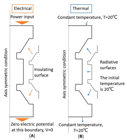
Figure 1.
Assumed spark plasma sintering (SPS) model’s boundary conditions for (A) electric and (B) thermal fields.
The electrical and thermal boundary conditions are summarized in Figure 1. Axially symmetric boundary conditions were applied along the axial axis. An electrical power input was applied to the upper ram while the lower one was grounded. The lateral surfaces of graphite elements were assumed to be electrically insulated. The initial temperature of all components was 20 °C, and the upper and lower ends were water-cooled and maintained at the preset temperature of 20 °C. The SPS process was operated in vacuum (≤5 Pa), so convection heat transfer was ignored. The heat on the graphite surface was mainly transferred to the environment by radiation, and the surface emissivity of graphite elements was assumed to be equal to 0.8 [32].
FEM conditions are summarized as follows. Parameters and formula settings of electric field.
No initial electric potential at all components.
Electric insulation boundary:
Provide the power input at this boundary (current density/electric potential):
where and are the power supply formula in voltage and current, respectively.
The electric current equation at the domain where the current passes is:
where , and are the electric conductivity, vacuum dielectric constant, and relative permittivity.
Parameters and formula settings of magnetic field.
Initial magnetic vector potential at all components:
Magnetic insulation boundary:
Coupling electric and magnetic fields:
where A, J, and are the magnetic vector potential, current density, permeability of vacuum, and relative permeability of the material.
3. Health Effects and Safe Distance for the Operators
During the electric current-assisted sintering process, large current can result in a strong magnetic field, which might exceed the safety exposure limits. To the best of our knowledge, such an issue has not been discussed in the literature. To meet the safety requirements, the resulting magnetic field should be kept under control. Exposure limits are inversely proportional to the frequency accordingly to the guidelines proposed by the International Commission on Non-Ionizing Radiation Protection in 2010 [33]. In DC, a well-accepted standard for the magnetic field exposure limit is 5 Gauss (0.0005 T), whereas for AC, the exposure frequencies differ from country to country.
Here, we simulated the magnetic field generated by reference SPS machines (FCT systems, Germany) operated in DC. The results are shown in Table 2 and Table 3, and as expected, the safety distance increases with the applied current (i.e., increasing the specimen dimension). The analysis in Table 2 also includes a conservative scenario where electromagnetic shielding (i.e., sintering chamber) is not employed. This assumption reflects the situation of unshielded or partially unshielded cables/conductors. The good match between simulated results and the Bio–Savart law confirms the accuracy of the simulations. The representative distribution of the magnetic field distribution is shown in Figure 2.
Table 2.
Safety distance test under DC conditions, for different currents assuming an exposure limit of 5 Gauss.
Table 3.
Electrical conductivity and relative magnetic permeability samples considered in the simulations 20 °C.
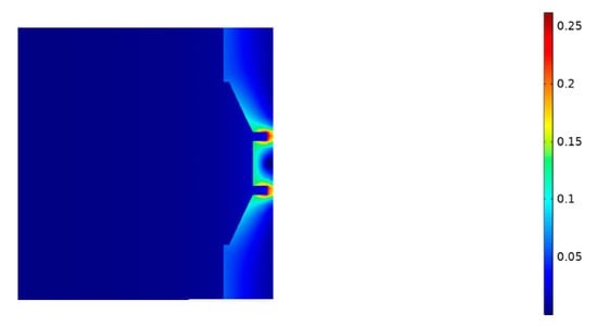
Figure 2.
Simulation of magnetic field distribution (units in Tesla) using an alumina sample with 30 mm diameter, and assuming a current of 3000 A DC and no sintering chamber (i.e., shield). The safety distance to meet the 5 Gauss line is 119 cm.
A more realistic simulation is instead achieved by considering a 2 cm-thick stainless steel chamber (relative permeability is 1.06) [34]. The results are presented in Figure 3. The magnetic field strength on the outside of the stainless steel is greatly reduced compared to the magnetic field strength on the inside, which shows that the stainless-steel shell can effectively reduce the magnetic field strength, thereby protecting the safety of the operator.
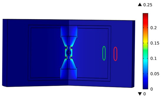
Figure 3.
Magnetic field distribution when using a 30 mm sample of alumina and current of 3000 A, adding a 2 cm-thickness stainless-steel shell. The magnetic field strength at the position represented by the green circle within the chamber is 1.94 × 10⁻³ T, while the magnetic field outside the chamber (red circle) is 1.218 × 10⁻⁷ T. The chamber can effectively shield the magnetic field down to a safe level for the operator.
4. Magnetic Field Distribution during SPS of Different Materials: Electrical Conductivity and Magnetic Permeability Effects
As discussed in the introduction, the ferromagnetic material below the Curie temperature is expected to become magnetized under the application of an electrical discharge. As a representative example, Sales et al. [26] investigated the changes in electrical resistance in the vicinity of the Curie temperature of ferromagnetic materials. These effects are summarized in Table 1 under the section “AC Resistance change in the vicinity of the Curie temperature.” Assuming a DC discharge, magnetization effects are expected to occur depending on the electrical conductivity and magnetic permeability, as shown in Table 3.
The SPS simulations were done assuming a DC voltage of 10 V DC that represents the upper operating limit of the equipment. The sample diameter of the sample was 30 mm with a height of the sample of 8 mm. The magnetic saturation of the 2.4 T effect for soft iron was accounted for in the simulations. The resulting magnetic field distribution is shown in Figure 4.
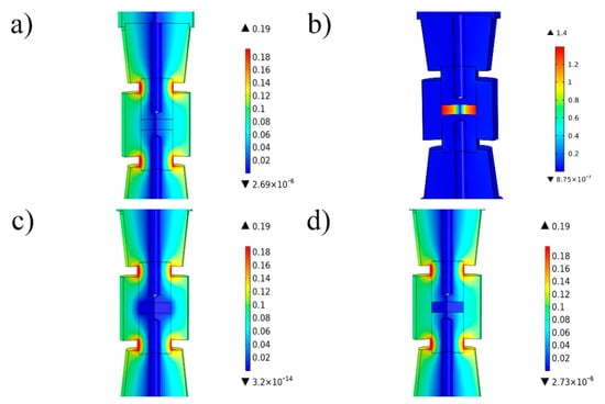
Figure 4.
Comparison of magnetic field distribution for different materials assuming a voltage of 10 V; (a) the maximum recorded field strength within the graphite sample was 0.053 T, (b) that for iron was 1.4 T, and (c) that for alumina was as low as 9.1 × 10⁻¹⁰ T. Simulations in (d) were performed at a temperature exceeding the Curie point, reaching 0.014 T within the iron sample.
According to Figure 4, the magnetic field strength depends strongly on the materials properties. For graphite and alumina, the magnetic field distribution is relatively uniform. The peak value of magnetic strength is 0.19 T, and it radially increases. For iron, the magnetic field distribution is different, the peak value of magnetic strength is 1.4 T (much larger than 0.19 T), and the magnetic intensity of the sample is much higher than those of the surrounding components. The intensity of the magnetic field increases with the radius and reaches the maximum value at the edge of the sample. It needs to be pointed out that the properties of ferromagnetic materials changed drastically when the temperature exceeded the Curie point, due to the ferromagnetic to paramagnetic transition. In Figure 4d, the temperature of the iron sample exceeded the Curie point, and the peak value of the magnetic field strength reduced from 1.4 to 0.19 T.
In the literature, there are some examples of sintering under the application of an externally applied magnetic field. For example, Eikeland et al. [35] investigated the externally applied magnetic field prior to sintering, resulting in an improved degree of alignment of SrFe12O19. Using a different approach, Li et al. [36] applied an external magnetic field using a inductor coil on iron-based powders using a field strength up to 0.5 T AC 50 Hz. The results suggested an enhanced diffusion of the alloying elements resulting from the application of an external magnetic field. The implications of these magnetic fields are not well-investigated, and it is expected that any magnetic-related effect might have a radial dependence. Further work might be needed to understand and exploit these effects.
5. Magnetic Field Effects at Interparticle Contacts
In this section, magnetic field effects occurring at the interparticle contact point are investigated. The analysis accounts for the impact of electro-magneto-thermal effects on the sintering process. Magnetic effects are intensified by increasing the current. Selected ECAS [37] techniques are rationalized in Table 4 with respect to pressure, discharge time, voltage, current, and sintered material compositions.
Table 4.
Representative sintering parameters for electric current-assisted sintering (ECAS) techniques based on high current density.
The electro-magnetothermal effect is summarized in Figure 5 for a copper sphere with a diameter of 100 µm and current density of 60 kA/cm2 (6 × 10⁸ A/m2) under a discharge time of 50 ms. The effect of the neck growth was investigated for contact areas of 154.94 and 754.77 μm2.
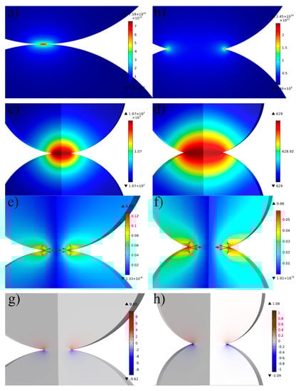
Figure 5.
Comparison of electro, thermal, and magnetic effects for 100 µm copper sphere discharged under a current density of 60 kA/cm2, with the first column for small contact area and second column for large contact area (154.94 and 754.77 μm2, respectively). (a) Current density distribution graph for small contact (peak current density was 7.59 × 10¹⁰ A/m2) and (b) large contact area (peak current density was 2.45 × 10¹⁰ A/m2). The temperature distribution graph under (c) small and (d) large contact area. Magnetic field distribution with arrows indicating the Lorentz force for (e) small contact area (peak magnetic intensity reached 0.13 T) and for (f) large contact area (peak magnetic intensity reached 0.06 T). Z-axis component Lorentz force contribution for (g) small contact area (max of 9.65 N/mm3) and (h) for large contact area (max of 1.08 N/mm3).
The boundary conditions were similar to those for the SPS model under a significantly increased current density.
The analysis of current density distribution is presented in Figure 5a,b. The current flows from top to bottom following the curvature of the particles, and it was subjected to the neck constriction effect. Analysis of temperature distribution (Figure 5c,d) suggests an even temperature distribution because of the high thermal diffusivity of copper; in reality, a temperature increase at the interparticle contact point should be expected because of contact resistance effects (not accounted by the proposed model). The contact resistance has an inverse dependence on the pressure. Analysis of the magnetic field strength distribution (Figure 5e,f) confirms strong magnetic effects at the interparticle contact point. The analysis of the Lorentz force distribution is presented using the arrows in Figure 5e,f. The resulting Lorentz force includes a radial compressive component and Z-axis repulsive component, which tend to repel the particles from each other. The Z-component Lorentz force plays a significant role in the molten metal ejection, and its color mapping distribution is shown in Figure 5g,h. This phenomenon has some analogies with the repulsion generated in metal wire explosion. It is even more commonly seen in welding as described in Ref. [38] In welding, this effect can be reduced by controlling the welding force, preventing the formation of a molten phase.
The magnetic forces are expected to be more significant for when paramagnetic copper is replaced with iron (diameter of the particles was 100 μm). The current density at the maximum cross-section through the copper powder was set at 60 and 200 kA/cm2 for iron. Figure 6 shows the contribution of the Z-axis for iron, where the Lorentz force reached the peak value of 321 N/mm3, far greater than the 9.65 N/mm3 for copper. This level of force is enough to affect the shape of the particle under such high current density.
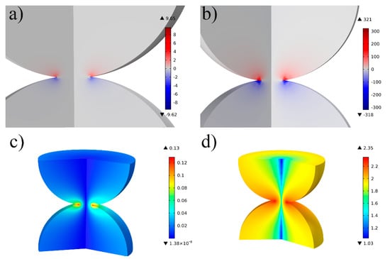
Figure 6.
Lorentz force z-axis contribution (a,b) and magnetic field distribution (c,d) in the case of copper (60 kA/cm2) in the first column and iron in the second column (200 kA/cm2).
The proposed model requires some experimental validation. For example, Guyot et al. [39] investigated the microscopic particle surface morphology on electrical discharge copper spheres with a diameter of 50 μm. Their results evidence the formation of molten droplets on the spheres possibly because of the Lorentz Force. In order to validate such an hypothesis, we employed 5 mm copper spheres, as shown in Figure 7.
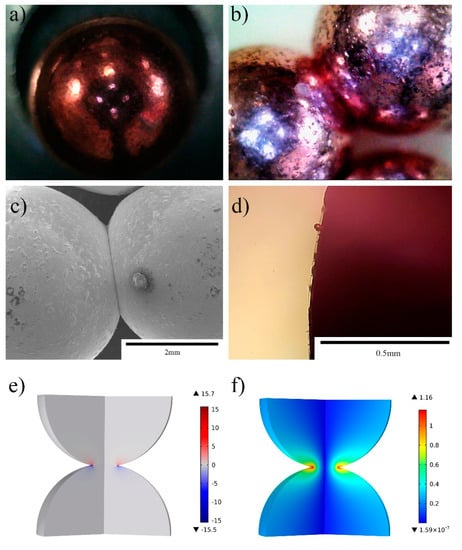
Figure 7.
(a) Surface morphology of as-received 5 mm copper spheres. (b,c) Overall appearance with optical microscope and SEM after application of a current of 15 kA/cm2 for 0.4 s. (d) Local appearance with optical microscope at a current 7.5 kA/cm2 for 0.6 s. (e,f) The Lorentz force contribution Z-component and the magnetic field strength distribution were simulated using a current of 15 kA/cm2 for 0.4 s, the Lorentz force peak value was 15.7 N/mm3, and the peak magnetic field strength was 1.16 T.
Figure 7a shows the surface of the copper ball before application of an electric current, and the surface was smooth. Figure 7b,c show the overall morphology of bonded particles after application of a 15 kA/cm2 discharge for 0.4 s. The two copper balls were bonded together well at the contact position. Surprisingly, there are many protrusions on the surface of the copper ball that might originate by the molten material being ejected due to the Lorentz force. Figure 7d shows a similar observation when using a current of 7.5 kA/cm2 for 0.6 s. Figure 7e,f map the Lorentz force and magnetic distribution, and the peak value was iron at 15.7 N/mm3, which is sufficient to promote molten metal ejection under a high current density [40].
The Joule heat generated by the high current softens or even partially melts the copper spheres at their interparticle contact. At the same time, the high current produces strong magnetic effects, and the liquid copper is ejected from the neck under the action of the repulsive Lorentz force, resulting in the formation of molten droplets, which reprecipitated on the spheres.
6. Conclusions
This article analyzed the possible role of magnetic fields on electric current-assisted processing. The first section surveyed these effects considering the Biot–Savart Law, skin effect, AC resistance change in the vicinity of the Curie temperature, proximity effect, pinch effect, and reactance dependence on duty cycle. By using finite element simulation, we could determine the safe distance (i.e., exclusion zone from the current conductor) for the operator. The second section simulates the magnetic field distribution at the tooling level (punch/die/sample assembly) during spark plasma sintering of the materials with variable electrical conductivity and different magnetic permeability. The same analysis was carried out at the interparticle level in the case of copper and iron spherical particles. The model was experimentally validated using 15 kA/cm2 for 0.4 s, where the molten droplet ejection was correlated with the strong repulsive Lorentz force acting on the molten copper. The results suggest that magnetic-related effects cannot be neglected when using ferromagnetic materials, when using extremely large currents. Further investigation should be dedicated to pulsing and frequency-related effects and how to exploit magnetic-related effects.
Author Contributions
S.G. contributed to the conception of the study. H.D. and S.G. performed the data analyses and wrote the manuscript. J.D., F.B. and T.S. contributed significantly to analysis and manuscript preparation. C.H. helped perform the analysis with constructive discussions. All authors have read and agreed to the published version of the manuscript.
Funding
This research received no external funding.
Acknowledgments
This work was supported by the Thousand Talents Program of China and Sichuan Province.
Conflicts of Interest
The authors declare no conflict of interest.
References
- Biesuz, M.; Sauders, T.; Ke, D.; Reece, M.J.; Hu, C.; Grasso, S. A review of electromagnetic processing of materials (EPM): Heating, sintering, joining and forming. J. Mater. Sci. Technol. 2020, 69, 239–272. [Google Scholar] [CrossRef]
- Guo, L.; Li, Y.Y.; Li, X.; Yang, J.Y. Numerical Analysis on Temperature Field of Axial Alternating Magnetic Field-Assisted Electric Field-Activated Sintering. Mater. Sci. Forum 2008, 575, 702–708. [Google Scholar] [CrossRef]
- Resistance Welder Manufacturers’ Association. Resistance Welding Manual, 4th ed.; Resistance Welder Manufacturers’ Association: Miami, FL, USA, 2009. [Google Scholar]
- Deffenbaugh, J.F. Resistance Welding; Resistance Welder Manufacturers Association: Miami, FL, USA, 1940; Volume 146. [Google Scholar] [CrossRef]
- Vikrant, K.; Wang, H.; Jana, A.; Wang, H.; García, R.E. Flash sintering incubation kinetics. NPJ Comput. Mater. 2020, 6, 1–8. [Google Scholar] [CrossRef]
- Semenov, A.S.; Trapp, J.; Nöthe, M.; Eberhardt, O.; Wallmersperger, T.; Kieback, B. Experimental and numerical analysis of the initial stage of field-assisted sintering of metals. J. Mater. Sci. 2017, 52, 1486–1500. [Google Scholar] [CrossRef]
- Ray, N.; Kempf, B.; Wiehl, G.; Mützel, T.; Heringhaus, F.; Froyen, L.; Vanmeensel, K.; Vleugels, J. Novel processing of Ag-WC electrical contact materials using spark plasma sintering. Mater. Des. 2017, 121, 262–271. [Google Scholar] [CrossRef]
- Grasso, S.; Saunders, T.; Porwal, H.; Cedillos-Barraza, O.; Jayaseelan, D.D.; Lee, W.E.; Reece, M.J. Flash Spark Plasma Sintering (FSPS) of Pure ZrB2. J. Am. Ceram. Soc. 2014, 97, 2405–2408. [Google Scholar] [CrossRef]
- White, D.A.; Fasenfest, B.J. Performance of Low-Rank QR Approximation of the Finite Element Biot-Savart Law. In Proceedings of the 2006 12th Biennial IEEE Conference on Electromagnetic Field Computation, Miami, FL, USA, 30 April–3 May 2006. [Google Scholar] [CrossRef]
- Wheeler, H. Formulas for the Skin Effect. Proc. IRE 1942, 30, 412–424. [Google Scholar] [CrossRef]
- Ahmad, M.K.; Ali, M.S.; Majid, A.; Saleem, J.; Kazmi, S.M.R. Design and optimization of high frequency (250 kHz) planar transformer for micro solar converter application. In Proceedings of the 2018 IEEE 12th International Conference on Compatibility, Power Electronics and Power Engineering (CPE-POWERENG 2018), Hilton Doha Hotel, Doha, Qatar, 10–12 April 2018. [Google Scholar]
- Runte, E. Continuous high-frequency induction tube welding. In The Brown Boveri Review; Brown, Boveri & Company: Baden, Switzerland, 1968; pp. 113–118. [Google Scholar]
- Zhao, D.X.; Zhao, Z.M.; Zhang, Z.K.; Dai, X. Research and Numerical Simulation of Contactor of High-Frequency Welding Device. Adv. Mater. Res. 2011, 189, 3575–3578. [Google Scholar] [CrossRef]
- Trapp, J. Mechanical Forces in the Microscopic Powder Contact during Field Assisted Sintering 2017; Fraunhofer Institute of Manufacturing and Advanced Materials—IFAM Dresden. Available online: http://doi.org/doi:10.13140/RG.2.2.14345.47206 (accessed on 1 July 2020).
- Yurlova, M.S.; Demenyuk, V.D.; Lebedeva, L.Y.; Dudina, D.V.; Grigoryev, E.G.; Olevsky, E.A. Electric pulse consolidation: An alternative to spark plasma sintering. J. Mater. Sci. 2013, 49, 952–985. [Google Scholar] [CrossRef]
- Ueyama, T.; Era, T.; Uezono, T.; Tong, H. Application of digital inverter-controlled AC pulsed MIG welding system to light metal joining. Weld. Int. 2011, 25, 676–682. [Google Scholar] [CrossRef]
- Yamaguchi, Y.; Katada, Y.; Itou, T.; Uesugi, Y.; Tanaka, Y.; Ishijima, T. Experimental investigation of magnetic arc blow in plasma arc cutting. Weld. World 2014, 59, 45–51. [Google Scholar] [CrossRef]
- Vural, M. Welding Processes and Technologies; Elsevier: London, UK, 2014; Volume 6, pp. 3–48. [Google Scholar] [CrossRef]
- Lockwood, L.F.; Phillips, A.L.; Walter, S.T. Welding Processes: Gas, Arc and Resistance. In Welding Handbook, 6th ed.; Cambridge University Press: Cambridge, UK, 1969; pp. 76–175. [Google Scholar] [CrossRef]
- Adamian, Y.; Shneerson, G. Mechanism of Wire Explosion Plasma Acceleration in Strong Axial Magnetic Field. Acta Phys. Pol. A 2009, 115, 1069–1071. [Google Scholar] [CrossRef]
- Zhang, H.; Senkara, J. Resistance Welding: Fundamentals and Applications, 1st ed.; CRC Press Taylor & Francis Group: Boca Raton, FL, USA, 2005. [Google Scholar] [CrossRef]
- Burkhard, D.G. A Heuristic Derivation of Coulomb’s Law and the Biot-Savart Law. Am. J. Phys. 1972, 40, 1858–1859. [Google Scholar] [CrossRef]
- Hovey, A. The Biot-Savart Law—Another Approach. Phys. Teach. 2008, 46, 261. [Google Scholar] [CrossRef]
- Lou, Y.-T.; Li, H.-Y.; Li, B.-M. Research on proximity effect of electromagnetic railgun. Def. Technol. 2016, 12, 223–226. [Google Scholar] [CrossRef]
- Dresden, M. Highest Pulsed Magnetic Fields in Science and Technology, Assisted by Advanced Finite-Element Simulations. In Proceedings of the COMSOL Conference 2008 Hannover, Hannover, Germany, 4–6 November 2008. [Google Scholar]
- Sales, B.C.; Maple, M.B. Low-frequency electrical resistance of iron, cobalt, and nickel in the vicinity of their Curie temperatures. Appl. Phys. A Solids Surf. 1983, 31, 115–117. [Google Scholar] [CrossRef]
- Mani, M.K.; Viola, G.; Hall, J.P.; Grasso, S.; Reece, M.J. Observation of Curie transition during spark plasma sintering of ferromagnetic materials. J. Magn. Magn. Mater. 2015, 382, 202–205. [Google Scholar] [CrossRef]
- Mal’Tsev, I.M. The effect of the electromagnetic field and skin and pinch effects on electrorolling metal powder materials under high-density pulse currents. Russ. J. Non-Ferrous Met. 2009, 50, 142–146. [Google Scholar] [CrossRef]
- Olevsky, E.A.; Dudina, D.V. Field-Assisted Sintering: Science and Applications; Spinger: Cham, Switzerland, 2018; pp. 1–425. [Google Scholar] [CrossRef]
- COMSOL Multiphysics. AC/DC Module User’s Guide. Vers.5.2; COMSOL: Stockholm, Sweden, 2015. [Google Scholar]
- Maizza, G.; Grasso, S.; Sakka, Y. Moving finite-element mesh model for aiding spark plasma sintering in current control mode of pure ultrafine WC powder. J. Mater. Sci. 2009, 44, 1219–1236. [Google Scholar] [CrossRef]
- Savvatimskiy, A. Measurements of the melting point of graphite and the properties of liquid carbon (a review for 1963–2003). Carbon 2005, 43, 1115–1142. [Google Scholar] [CrossRef]
- Guidelines for limiting exposure to time-varying electric and magnetic fields (1 Hz to 100 kHz). Health Phys. 2010, 99, 818–836. [CrossRef]
- Bowler, N. Four-point potential drop measurements for materials characterization. Meas. Sci. Technol. 2010, 22. [Google Scholar] [CrossRef]
- Eikeland, A.Z.; Stingaciu, M.; Granados-Miralles, C.; Saura-Múzquiz, M.; Andersen, H.L.; Christensen, M. Enhancement of magnetic properties by spark plasma sintering of hydrothermally synthesised SrFe12O19. CrystEngComm 2017, 19, 1400–1407. [Google Scholar] [CrossRef]
- Li, X.; Ye, Y.; Tang, Y.; Qu, S. Effect of Pulsed Magnetic Field on Spark Plasma Sintering of Iron-Based Powders. Mater. Trans. 2010, 51, 1308–1312. [Google Scholar] [CrossRef]
- Grasso, S.; Sakka, Y.; Maizza, G. Electric current activated/assisted sintering (ECAS): A review of patents 1906–2008. Sci. Technol. Adv. Mater. 2009, 10, 053001. [Google Scholar] [CrossRef] [PubMed]
- Kvartskhava, I.F.; Bondarenko, V.V.; Meladze, R.D.; Suladze, K.V. Electrical Explosion of Wires in Vacuum. Sov. Phys. JETP 1957, 4, 637–644. [Google Scholar]
- Guyot, P.; Rat, V.; Coudert, J.F.; Jay, F.; Maître, A.; Pradeilles, N. Does the Branly effect occur in spark plasma sintering? J. Phys. D Appl. Phys. 2012, 45. [Google Scholar] [CrossRef]
- Magonov, S.N.; Reneker, D.H. Characterization of Polymer Surfaces with Atomic Force Microscopy. Annu. Rev. Mater. Res. 1997, 27, 175–222. [Google Scholar] [CrossRef]


Publisher’s Note: MDPI stays neutral with regard to jurisdictional claims in published maps and institutional affiliations. |
© 2020 by the authors. Licensee MDPI, Basel, Switzerland. This article is an open access article distributed under the terms and conditions of the Creative Commons Attribution (CC BY) license (http://creativecommons.org/licenses/by/4.0/).