1. Introduction
1.1. Vibrations: Mechanical Impedance
The transmission of vibrations through a structure and systems to reduce, mitigate or suppress them has been profusely studied in mechanical engineering. Any structure behaves as a vibration path or “circuit” for an oscillatory mechanical excitation and it can be characterized by a “dynamic transfer function” which is strongly dependent on frequency [
1].
The combination of stiffness, inertia and damping is just the basics of vibration control [
2]. The simplest way to reduce vibration transmissibility of, for example, a rotating machine to the ground is to increase the elasticity of the ground connections. In this sense, elastic couplings are extensively used in industry and buildings, and floating benches are typically used to support vibrating machinery. For example, a simple passive double floating bench with soft supports achieves a 20 dB reduction in vibration level [
3]. In general, quite good vibration isolation can be obtained by appropriate design of these benches. However, it becomes more difficult to isolate low frequency vibrations [
4].
The mechanical impedance of a vibratory system is defined as:
where F is the acting force and v the response velocity.
The combination of mechanical elements can be characterized by their equivalent impedance [
5]. Well-known techniques can be used to calculate this equivalent impedance, the response of a vibratory system to a given dynamic load, e.g., Kirchhoff’s law, the reciprocity and the superposition theorem, or the Thevenin equivalent systems, all of them with their limitations [
6].
Electrical engineers developed methods for matching impedances to maximize/minimize power transfer/reflection from the load. Essential elements for electrical systems are transformers that multiply voltage and divide current or vice versa. Although the same principle could be applied to mechanical (vibrational) circuits, up to now nobody has developed any effective analogue mechanical transformer to help mechanical engineers.
Indeed, wonderful example of mechanical impedance matching can be found in nature. The ears of most terrestrial animals are provided with mechanical impedance transformers. While the medium in the outer ear is obviously air, the medium in the inner ear is a liquid similar to water. Both of these elements present quite different mechanical impedances. Because of the difference in the impedances of the air and the liquid in the inner ear, a hearing loss of about 30 dB should be expected. However, a set of small bones in the middle air (hammer, incus and stapes) compliantly attached, together with the different areas of the tympanic membrane and the oval window, provides a mechanical advantage so that it compensates for this hearing loss. This mechanical impedance coupling is an example of mechanical transformer.
Despite the illustration of this example, it is not easy to find similar mechanical devices that take advantage of the impedance matching to operate. Impedance coupling or impedance matching could be a powerful key technique for the control of the vibrations in a mechanical system, but a sensitive multiplier mechanism is required.
Conventional gears or drivers present a macroscopic backlash and hysteresis that make them not suitable for the transmission of vibrations. A zero-backlash mechanism would be required for this task.
In this paper, a new technology of zero-backlash magneto-mechanisms has been optimized for matching mechanical impedances. Particularly, the case of an integrated, optimized, mechanically matched damper [
7] is shown.
1.2. Magnetic Harmonic Gear for Matching of Mechanical Impedances and Magnetic Dampers
Magnetic Harmonic Drives (so called MAGDRIVES are non-contact mechanisms able to provide a reduction or multiplication of movement with no significant backlash [
8].
They present remarkable advantages with respect to classic harmonic drives. As there is no contact between the movable members, wear and fatigue are minimized and no lubrication is needed. Therefore, minimum maintenance is required and lifetime is maximized, gently overpassing that of mechanical devices.
Another interesting feature of the magnetic gear is their anti-jamming intrinsic property: when torque exceeds a threshold the input slides smoothly, preventing the breakdown of the device or other mechanical devices that are kinematically connected. Moreover, this technology presents inherent damping and reduction of vibrations that can be tuned by design.
However, the most useful property of the MAGDRIVE is that its backlash is virtually zero, therefore providing a smooth and continuous transmission [
9,
10].
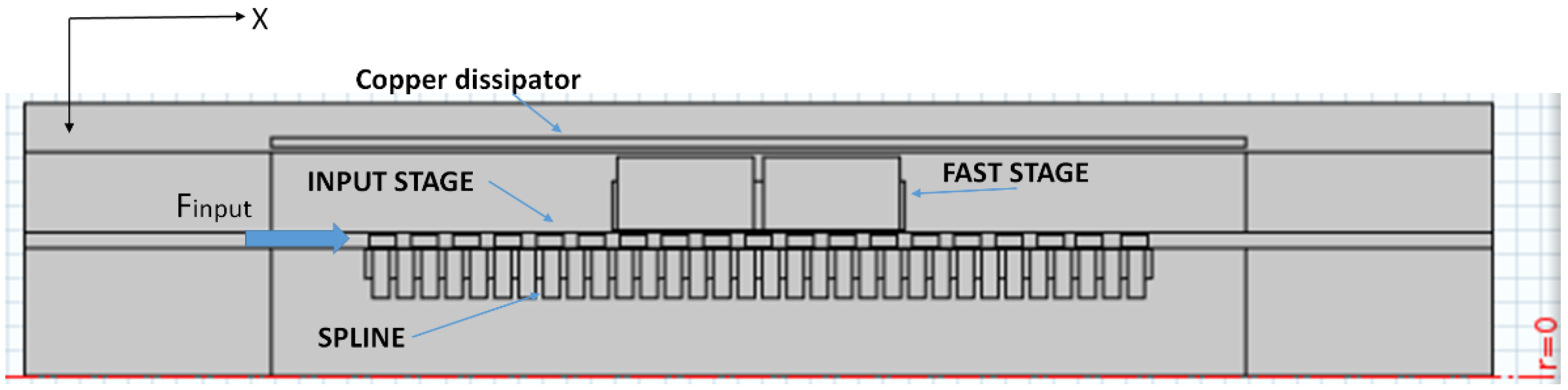
The MAGDRIVE working principle is applicable to both linear and rotational systems. The working principle is simple: an input stage, composed of soft magnetic teeth, which is externally actuated generates a magnetic wave that interacts with a linear spline of magnets and a fast stage of permanent magnets. Depending on the relative number of teeth in the input stage and the linear spline, a reduction/amplification relationship is automatically defined with zero backlash as shown in
Figure 1.
Relative displacement and force transmission will depend directly on this relationship. An amplification displacement stage could be designed following this principle. As its backlash is zero, this mechanism can be used as a mechanical impedance matching coupler.
In the same manner, mechanical impedance couplers that can be obtained by this new kind of zero-backlash mechanism provide the way to optimize and get the best of all kinds of vibration attenuation systems. Mechanical impedance will be transformed proportionally to the square of the ratio.
For instance, a small piezoelectric actuator can be coupled to provide a large displacement to deal with large-amplitude vibrations. Also, for instance, a damper, whose efficiency increases with velocity, would enhance its efficiency when coupled through a velocity multiplier.
1.3. Magnetic Dampers
Typical magnetic dampers are based in the induction of electrical eddy currents [
11]. When a conductor is exposed to an alternating magnetic field, a power loss appears which is proportional to the square of the frequency of the oscillation. In this way, the kinematic energy from the vibration can be dissipated and not transmitted to the structure. An arrangement of permanent magnets oscillating inside a conductive element is the most common design [
12].
Several examples can be found of this sort of damper that exhibits relatively high spring coefficients, loss factors over 1.2 and damping densities up to 1060 kNs/m/m3, even at low frequencies. In addition, these systems can operate up to a maximum temperature of about 310 °C for SmCo magnets, with improved performance at low temperatures, and they are fully passive and do not have contact between the moving parts, minimizing wear and fatigue in the mechanical elements, and have a null time of response.
Even though previous prototypes that have been explored are far from optimized in terms of weight and cost, they exhibit a promising performance in comparison to other damping systems.
This technology has been used successfully in the automotive industry [
13] and in aerospace applications, such as in magnetic damping in rotor vibration [
14] or for the isolation of structural vibrations in inflatable satellites [
6].
However, their main limitation is their poor performance at low frequency vibrations. Dissipated power depends on the square of the frequency. Therefore, they are perfect candidates to be improved using impedance matching. Should speed be multiplied by n times, the dissipated power would increase n
2 times. In addition, non-linear effects are usually present in the system [
15].
Other magnetic technologies for damping are magnetorheological dampers which, in addition, can be tuned to operate under different damping parameters [
16].
Additionally, magnetic dampers can naturally be integrated in MAGDRIVES, creating a compact and efficient device.
In conclusion, the objective of this paper is to present the combination and integration of a magnetic linear gear acting as an impedance coupling device with an eddy current dissipater. The use of impedance matching improves the efficiency of the eddy current dissipater significantly. In addition, the lack of lubrication requirements makes possible the utilization of the Z-damper at temperature only limited by the materials. In this paper, a study on the performance of a Z-Damper operating in an environment at 200 °C is discussed.
1.4. Thermal Constrictions
The absence of friction makes the device not need lubrication. This device can therefore virtually operate from very low temperatures (−200 °C) to relatively high temperatures, limited only by the Curie temperature of the magnetic materials (up to 350 °C with NdFeB permanent magnets and more than 500 °C for ferrites) without significant changes in its performance.
The maximum working temperature of some commercially available permanent magnets is summarized in
Table 1.
Although magnetic materials suitable for high temperature present poorer performance at room temperature, it seems feasible to use them for the development of devices intended for “high” temperature. Obviously a trade-off is necessary to optimize the design of a coupler.
In this way, the objective of the “Z-damper” project is to develop a prototype of a “magneto-mechanically coupled magnetic damper” with a working temperature of 200 °C. The expected performance of such a device according to multiphysics simulations is shown in this paper.
2. Design and Method
A “magneto-mechanically coupled magnetic damper” (the so-called Z-Damper) prototype has been designed to fulfill the role of an integrated high temperature damper with the capability of working at environmental temperatures up to 200 °C with continuous operation. A complete detailed design has been carried out and all the elements have been modeled for multiphysics simulations. These comprise the following:
Magneto-mechanical coupled simulations for the modeling and design of the magnetic parts, including the dissipative elements. Dynamic behavior has been modeled. Heat generation figures have been obtained from eddy current dissipation in the electric conducting elements.
Thermal simulations and analytical calculations have been carried out in order to obtain the temperature profiles inside the devices and to determine the ventilation requirements. The design of the prototype has been optimized for a maximum heat internal evacuation. Thermal expansion and possible thermal-induced stress have been analyzed as well.
A structural assessment has been carried out, including static mechanical stress and deflections as well as fatigue estimations, to assure the integrity of the devices under highly oscillating loads.
The Z-Damper is composed of three different moving stages:
Slow stage or input stage: connected directly to the source of the vibration.
Fast stage: magnetically coupled with the other stages and able to generate dissipative eddy currents.
Spline: fixed layer provided with a set of permanent magnets.
A 2-mm-thick copper dissipater fixed to the stator part of the device where the eddy currents are dissipated mainly due to the amplified motion of the fast stage.
For the device described in this paper, the materials detailed in
Table 2 were considered:
The absence of friction makes the Z-Damper not need lubrication. This device can therefore virtually operate from very low temperatures (−200 °C) to relatively high temperatures, limited only by the maximum temperature of the continuous service of the permanent magnets (up to 825 °C with thermal-stabilized SmCo magnets).
The prototype would be connected on one side to the source of the vibrations and on the other side to the ground of the system or the part to be isolated.
Figure 2 represents the design model used for simulations.
The motion equations for the system read:
For the fast moving stage,
where
m is the mass of the fast moving stage,
Xfast is the position of the fast stage,
t is time,
and is the contribution of all the magnetic forces on the fast stage.
For the input stage,
where
M is the mass of the input moving stage,
Xinput is the input position,
and is the contribution of all the magnetic forces acting on the input stage.
The movement of the fast and the slow stages will be related through an impedance coupling number
n. This means that the ratio between the input force and that exerted by the fast element equals
n. Alternatively, we can say that this is also the ratio between the displacement of the fast stage over the displacement of the input stage:
In the quasi-static case, n = 7 is derived from the number of teeth.
Figure 2 represents the Z-Damper prototype connections.
Table 3 summarizes the most relevant parameters expected from the Z-Damper prototype.
3. Results
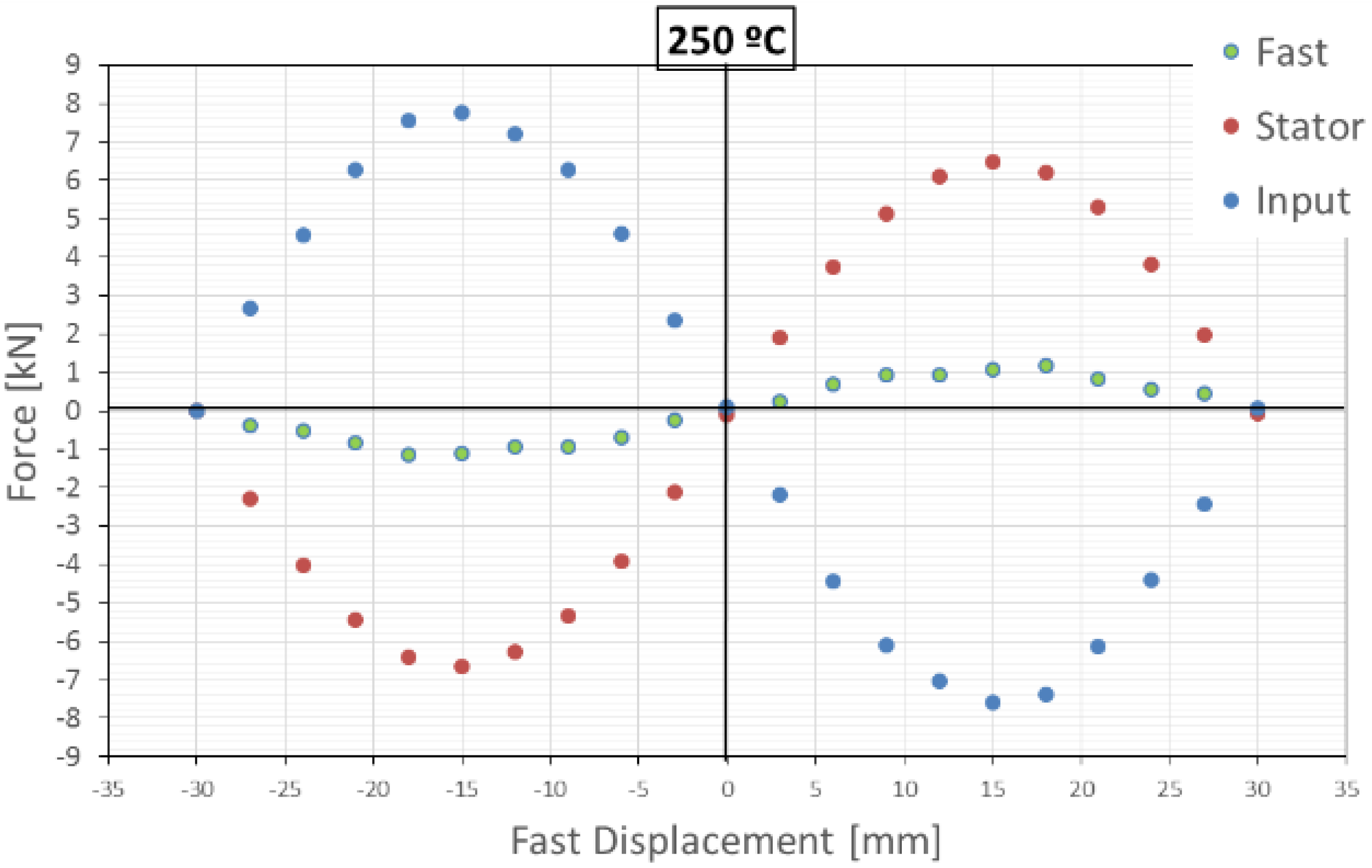
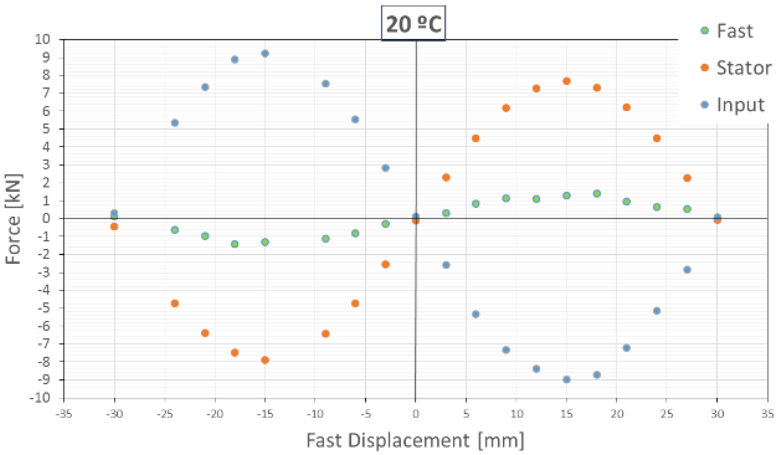
3.1. Z-Damper: Magnetostatic FEM Simulations
The maximum available force (e.g., for damping) of the device, the stiffness and the natural frequency can be obtained from magnetostatic finite element method simulations. The simulations are done while fixing the stator and input (no motion allowed) and just moving the fast part along the stroke of the device. This situation represents an infinite load on the output shaft.
Due to the periodic distribution of magnets, the results for any other position of the input are essentially the same, except for a shift of the fast stage.
Figure 3 and
Figure 4 show the force
vs. displacement of the fast moving stage when the motion of the input stage is locked at 20 °C and at 250 °C.
A local stiffness of 112 N/mm is found around the rest position for 250 °C.
3.2. Z-Damper: Dynamics
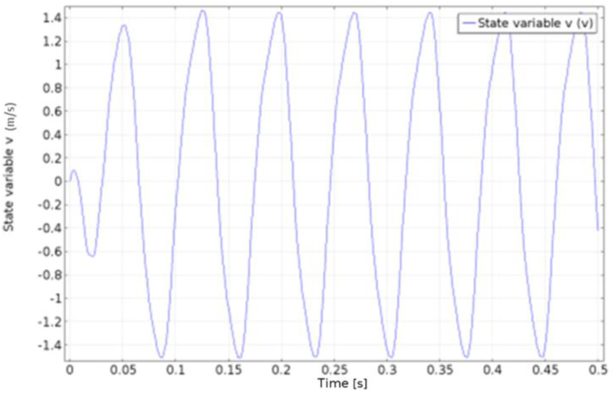
If the input stage is forced to move harmonically, then the fast stage will oscillate with a larger amplitude than that of the slow stage.
Figure 5 shows how a stationary state is quickly reached in this case.
For dynamic calculations, the internal temperature of the Z-Damper has been considered uniform and equal to 250 °C. This approximation is considered accurate because the maximum variation of the internal temperature from that value is 17 °C. In addition, 250 °C can be considered as the average internal temperature. Considering the operation of the Z-Damper in a frequency bandwidth of 0 to 100 Hz, the skin depth for a copper conductor is
Considering the following values at 250 °C:
ρ = 3.1·10−8 Ω/m at 250 °C, the frequency is 100 Hz, and μ is the magnetic permeability of the material and equal to 4π·10−7 A/m, and f is the magnetic field variation frequency, in this case coincident with the input motion frequency.
Therefore, skin depth at 100 Hz is about 9 mm, considerably larger than the copper dissipater thickness, which clearly dominated power dissipation in the Z-Damper.
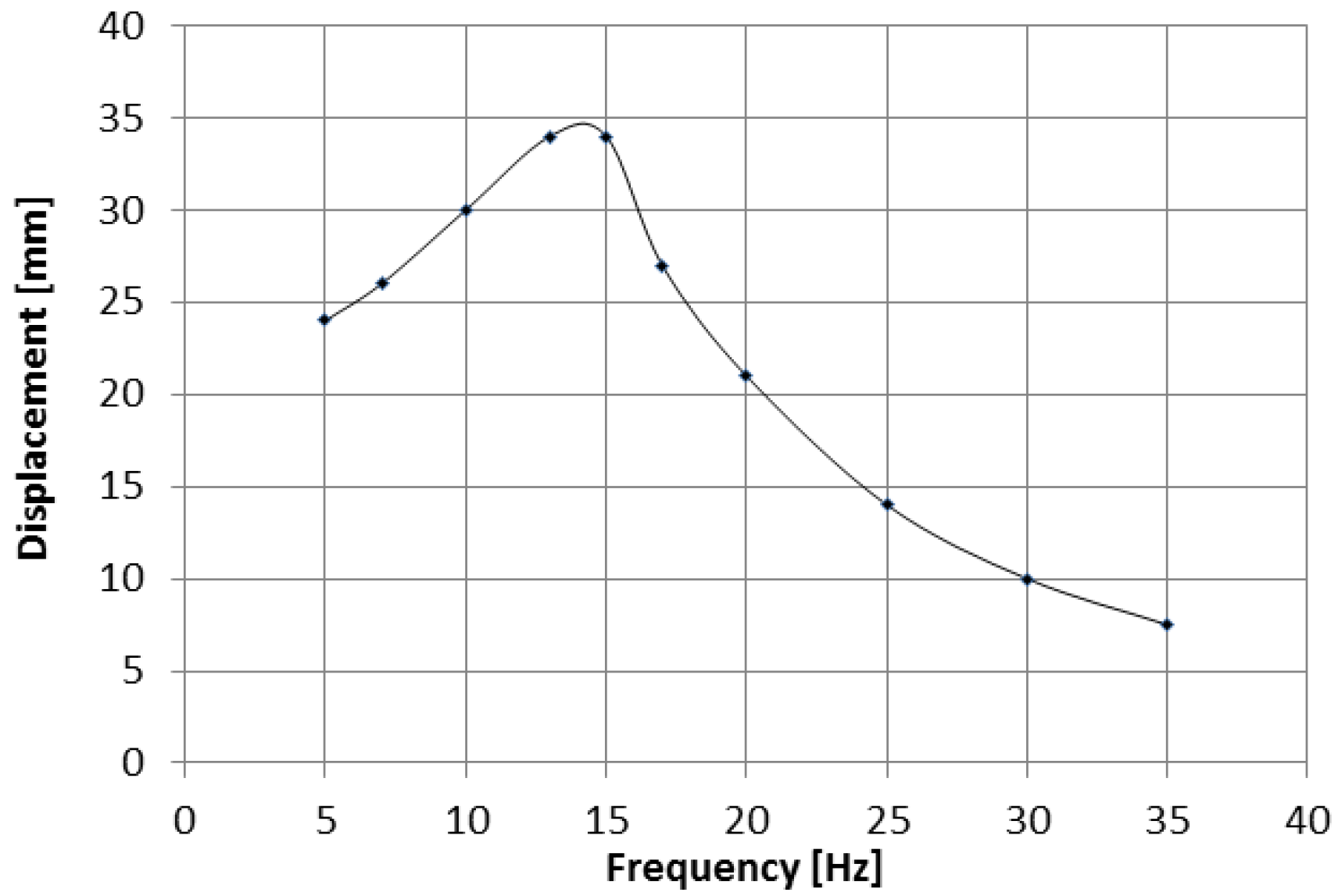
The amplitude of the fast moving stage displacement for the input oscillation amplitude of 3 mm
vs. the frequency is represented in
Figure 6. While the static ratio of
n = 7 stands at 0 Hz, a resonance is evident at around 15 Hz.
3.3. Z-Damper: Damping and Dissipated Power
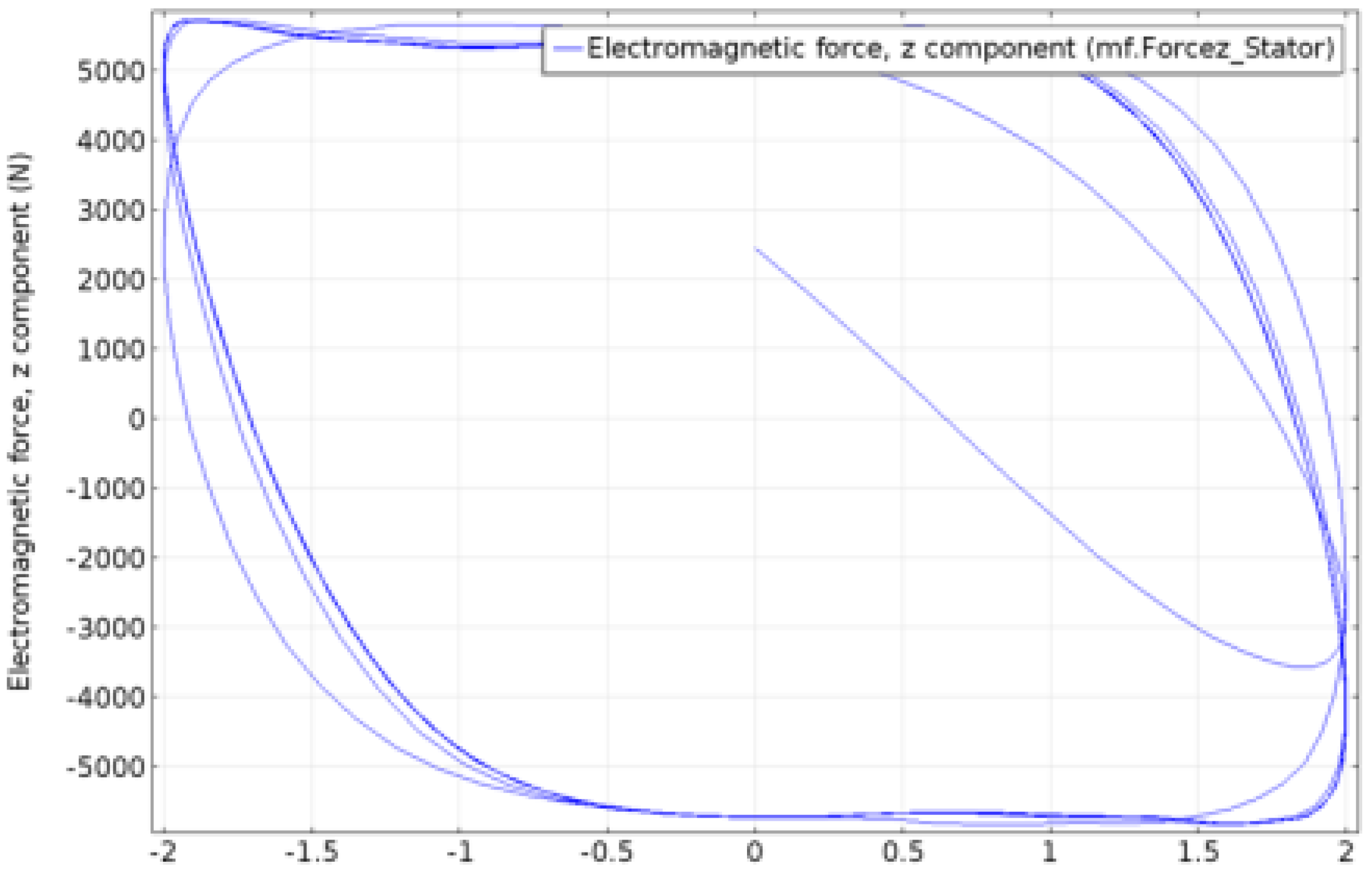
Figure 7 shows the input force required for achieving such a harmonic movement of the input element
vs. its displacement. It can be seen that the hysteretic cycles followed by the system are close to being square, which is much more efficient than any other kind damper.
The energy associated with the hysteresis cycle in
Figure 7 can be calculated as:
where
At the steady-state solution, it can also be expressed as [
17],
Solving the previous equation, the damping coefficient obtained is:
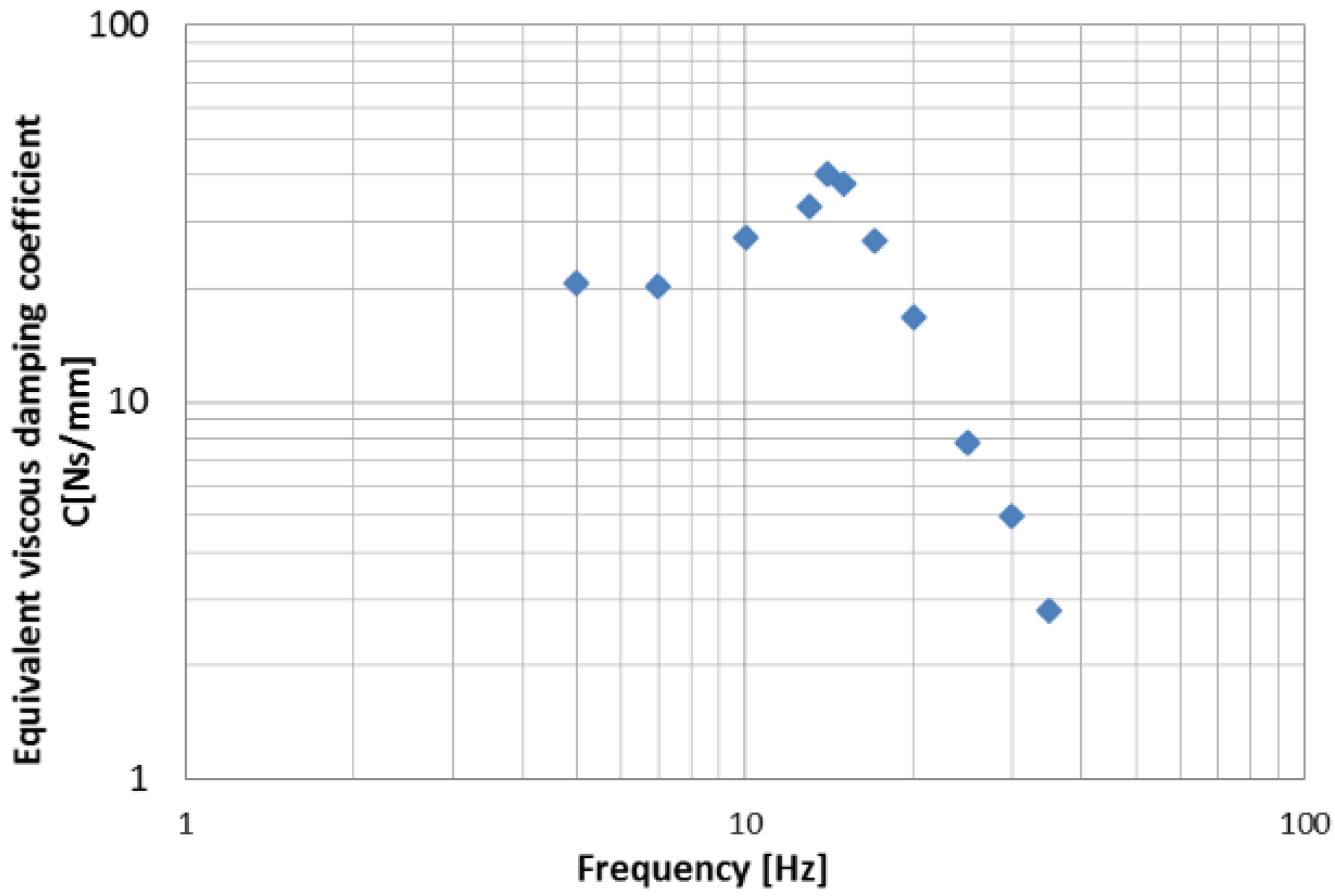
The equivalent viscous damping coefficient
vs. the input oscillation frequency is plotted in
Figure 8 for an input displacement amplitude of 3 mm:
Note that the equivalent viscous damping coefficient at the input stage is clearly improved by the resonance on the fast stage at its resonant frequency. For excitation frequencies close to the resonant frequency, the displacement (and velocity) of the fast stage is multiplied, enhancing the magnetic damping on the copper dissipater. A simple interpretation of the physical phenomenon can be done in terms of impedance coupling between the vibration source and the eddy current damper. As the impedance coupler depends on frequency as a typical “elastic” support, there is a sort of disconnection over the resonance frequency. This is quite positive as the lower the damping coefficient is, the larger the vibration attenuation of an elastic suspension at high frequency is.
Additionally, the resonant behavior increases the speed of the fast stage up to the resonant frequency, providing a much greater effectiveness in generating eddy currents and therefore in the overall damping effectiveness.
4. Conclusions
“Magneto-mechanically coupled magnetic dampers”, the so-called Z-Dampers, provide a new tool for vibration damping. Multiphysics simulations of a Z-Damper prototype show that the effect of multiplication of the displacement (impedance coupling) associated with the linear magnetic gear (with no backlash) greatly enhances the damping effectivity of an integrated magnetic eddy current damper.
Dynamic hysteric cycles of the Z-Damper show an unusual and unique behavior: the energy losses per cycle are close to being the maximum of what is physically possible, proportionally much larger than for any other damper. This property itself can be considered a breakthrough for vibration damping as it enhances the efficiency of dissipation of energy per cycle at least an order of magnitude.
Additionally, as can be seen in
Figure 8, the equivalent viscous damping coefficient is far from being constant with the frequency; it presents a maximum in the resonant frequency and it decreases with the frequency over it.
In a conventional lineal system, the damping coefficient remains constant and the general tendency is to reach the highest damping level possible at low frequencies, while at high frequencies the higher the regression coefficient is, the worse the efficiency of the system turns.
As it has been illustrated by the results of the simulations, the coefficients of the Z-Damper at low frequencies remain high; however, they decrease at high frequencies. This allows an incredibly high damping at low frequencies and, at the same time, the improvement of the behavior of the system at high frequencies which leads to the system’s optimum performance.
These exceptional results at low and high frequencies make this kind of device much more beneficial than systems based on viscosity or viscoelasticity.
Furthermore, the application of these mechanical advantages will prove to be essential in low frequency situations such as anti-seismic regression scenarios, in which it would also be worth considering the possibility of customizing the maximum frequency in order to accomplish the best damping coefficient possible.
Acknowledgments
This work has been partially funded by the Seventh Framework Clean Sky Program of the EU Commission, under grant JTI-CS-2013-02-SFWA-03-013.
Author Contributions
J.L. Perez-Diaz contributed as main inventor of the technology and in the development of the device conceptual design, I. Valiente-Blanco defined the materials and specifications for the design and performed part of the simulations. Cristian Cristache developed most of the FEM simulations and contributed to the device design.
Conflicts of Interest
The authors declare no conflict of interest.
References
- Guo, P.F.; Lang, Z.Q.; Peng, Z.K. Analysis and design of the force and displacement transmissibility of nonlinear viscous damper based vibration isolation systems. Nonlinear Dyn. 2012, 67, 2671–2687. [Google Scholar] [CrossRef]
- Guo, D.; Hu, H. Nonlinear Stiffness of a Magneto-Rheological Damper. Nonlinear Dyn. 2004, 40, 241–249. [Google Scholar] [CrossRef]
- Álvarez Valenzuela, M.A.; Díaz García, J.A.; Perez-Diaz, J.L. Análisis de la sensibilidad a las vibraciones del método de medición de tensión superficial mediante gota suspendida. Rev. Mex. Fis. 2010, 56, 334–338. [Google Scholar]
- Hartley, T.T.; Lorenzo, C.F. A Frequency-Domain Approach to Optimal Fractional-Order Damping. Nonlinear Dyn. 2004, 38, 69–84. [Google Scholar] [CrossRef]
- Beranek, L. Acoustics; McGraw-Hill Book Co. Inc.: New York, NY, USA, 1954. [Google Scholar]
- Hixson, E.L. Mechanical Impedance and Mobility. In Shock and Vibration Handbook, 1st ed.; Harris, C.M., Crede, C.E., Eds.; McGraw-Hill Book Company, Inc.: New York, NY, USA, 1961. [Google Scholar]
- Jing, X.J.; Lang, Z.Q.; Billings, S.A.; Tomlinson, G.R. Frequency domain analysis for suppression of output vibration from periodic disturbance using nonlinearities. J. Sound Vib. 2008, 314, 536–557. [Google Scholar] [CrossRef]
- Jing, X.J. Nonlinear Characteristic Output Spectrum for Nonlinear Analysis and Design. IEEE/ASME Trans. Mechatron. 2014, 19, 171–183. [Google Scholar]
- Pérez-Díaz, J.L.; Valiente-Blanco, I.; Cristache, C.; Díez-Jiménez, E. Enhanced Magnetic Vibration Damper with Mechanical Impedance Matching. European Patent EP15382461, 23 September 2015. [Google Scholar]
- Pérez-Diaz, J.L.; Garcia-Prada, J.C.; Valiente-Blanco, I.; Diez-Jimenez, E. Magnetic-Superconductor Cryogenic Non-contact Harmonic Drive: Performance and Dynamical Behavior. New Trends Mech. Mach. Sci. 2013, 7, 357–364. [Google Scholar]
- Pérez-Díaz, J.L.; Diez-Jimenez, E.; Valiente-Blanco, I.; Cristache, C.; Alvarez-Valenzuela, M.-A.; Sanchez-Garcia-Casarrubios, J.; Ferdeghini, C.; Canepa, F.; Hornig, W.; Carbone, G.; et al. Performance of Magnetic-Superconductor Non-Contact Harmonic Drive for Cryogenic Space Applications. Machines 2015, 3, 138–156. [Google Scholar] [CrossRef]
- Ebrahimi, B.; Khameseeand, M.B.; Golnaraghi, F. Eddy current damper feasibility in automobile suspension: Modeling, simulation and testing. Smart Mater. Struct. 2009, 18, 015017. [Google Scholar] [CrossRef]
- Pontes, B.R., Jr.; Silveira, M.; Mazotti, A.C.; Gonçalves, P.J.P.; Balthazar, J.M. Contribution of electrical parameters on the dynamical behavior of a nonlinear electromagnetic damper. Nonlinear Dyn. 2014, 79, 1957–1969. [Google Scholar] [CrossRef]
- Frederick, J.R.; Darlow, M.S. Operation of an electromagnetic eddy current damper. ASME J. Vib. Acoust. 1994, 116, 578–580. [Google Scholar] [CrossRef]
- Jing, X.J.; Lang, Z.Q. Frequency domain analysis of a dimensionless cubic nonlinear damping system subject to harmonic input. Nonlinear Dyn. 2009, 58, 469–485. [Google Scholar] [CrossRef]
- Zhu, X.; Jing, X.J.; Cheng, J. A magnetorheological fluid embedded pneumatic vibration isolator allowing independently adjustable stiffness and damping. Smart Mater. Struct. 2011, 20, 085025. [Google Scholar] [CrossRef]
- Stutts, D.S. Equivalent Viscous Damping. Available online: http://web.mst.edu/~stutts/SupplementalNotes/EqivalentViscousDamping.pdf (accessed on 8 June 2016).
© 2016 by the authors; licensee MDPI, Basel, Switzerland. This article is an open access article distributed under the terms and conditions of the Creative Commons Attribution (CC-BY) license (http://creativecommons.org/licenses/by/4.0/).


