Article

Employing Dye-Sensitized Solar Arrays and Synchronous Reluctance Motors to Improve the Total Cost and Energy Efficiency of Solar Water-Pumping Systems

1
Electrical Engineering Department, Kafrelsheikh University, Kafr El-Sheikh 33511, Egypt
2
Institute of Nanoscience and Nanotechnology, National Center for Scientific Research “Demokritos”, Agia Paraskevi Attikis, 15341 Athens, Greece
3
Department of Electromechanical, Systems and Metal Engineering, Ghent University, 9000 Ghent, Belgium
4
Flanders Make@ UGent—Corelab EEDT-MP, 3001 Leuven, Belgium
5
Electrical and Computer Engineering Department, University of the Peloponnese, 26334 Patras, Greece
*
Author to whom correspondence should be addressed.
Machines 2022, 10(10), 882; https://doi.org/10.3390/machines10100882
Submission received: 1 September 2022 / Revised: 26 September 2022 / Accepted: 26 September 2022 / Published: 1 October 2022
(This article belongs to the Special Issue Renewable Energy Power Plants and Systems)

Abstract

:
In this work, a proposed high-efficiency and low-cost photovoltaic water-pumping system based on semitransparent dye-sensitized solar cells (DSSCs) is presented. DSSCs are low-cost third-generation photovoltaics that have gained a lot of interest as a promising alternative for silicon solar cells. DSSCs are fabricated at low cost and low temperature and present power conversions with high efficiency, exceeding 14%, thanks to high transparency, a variety of colors, and high efficiency, even in low light conditions. The DSSC modules used in this study were tested under different working conditions, and their characteristics were determined experimentally and simulated theoretically via MATLAB. A complete laboratory infrastructure is constructed to test the proposed photovoltaic water-pumping system based on the DSSC module array. The system contains a synchronous reluctance motor driving a water pump and feeding from the DSSCs via an inverter without DC–DC converters or batteries. The proposed system has many merits, such as high efficiency and low cost. The DSSCs’ maximum available power is obtained via a maximum power point tracking technique (perturb-and-observe). Moreover, a control system for driving the motor via the inverter was also implemented. The maximum torque per ampere strategy is also considered in the proposed control system to drive the motor efficiently using the inverter. Finally, experimental validation of the complete system via laboratory measurements is implemented.

1. Introduction

Since the industrial revolution, humans have introduced a lot of carbon dioxide into the atmosphere, at a rate higher than that the trees can recycle it, resulting in global warming. Solar light can be converted into electrical energy via photovoltaic (PV) technologies, leading to energy harvesting without any carbon emission (green energy) [1,2,3,4]. PV technologies comprise conventional silicon solar cells [5,6,7,8], thin film technologies [9], and the dye-sensitized solar cells proposed by Gratzel in 1991, from which perovskite solar cells have also emerged [10,11,12,13]; the study used interface engineering to obtain highly efficient perovskite solar cells. In [14,15,16], the researchers used the dye-sensitization approach to fabricate efficient and stable perovskite solar cells. The work presented in [17,18] discussed the dye-sensitization approach in DSSCs and showed its efficiency. DSSCs use transition metal complexes or organic dyes as light-absorbing materials [19]. The DSSCs are easily fabricated via solution processes and their efficiency reaches 14%. In contrast with silicon solar cells, DSSCs provide power output in an efficient way under all illumination conditions, including natural (diffuse/full solar) and technical (LED and fluorescent) lighting. DSSCs consist of four main components, namely, the photosensitizer (dye), acting as light capturing antenna and electron injector; the electrolyte, for the regeneration of the dye; the working electrode (a mesoporous TiO2 thin film), for electron conduction and collection; and the counter electrode (Pt), for redox couple renewal (Figure 1a). In [20,21,22], the researchers used DSSCs as a source of electricity for the internet of things; they also used TiO2 to improve the performance of the DSSCs and tested the DSSCs under different operation conditions, respectively. The contributions to the development of ruthenium-based sensitizers for dye-sensitized solar cells are discussed in [23], while incorporating novel Co(II/III) based-redox electrolytes solidified by silica nanoparticles is presented in [24]. In [25], the annealing effects on self-assembled TiO2 nanotubes and their behavior as photoelectrodes in dye-sensitized solar cells are discussed. In [26,27,28], high-efficiency DSSCs based on redox electrolytes are presented.
Characterized by rapid efficiency increase and low-cost production, third-generation PVs, especially dye-sensitized solar cells, are a very promising renewable energy technology. These systems can be used on-grid connected or off-grid connected working modes. In this context, off-grid PV technology is used in rural regions where there is no electricity and the connection to the nearest grid is very costly. The off-grid system is used in a wide range of water-pumping systems for crop irrigation in the desert [29].
Water-pumping systems based on PV technology have been intensively studied for efficiency improvement and cost reduction [30,31,32,33,34,35,36,37,38,39,40,41]. DC motors were firstly used in water-pumping systems because they can easily be connected directly to the PV source or via DC–DC converter. However, DC motors require continuous maintenance for their brushes and commutators, besides efficiency optimization and cost reduction issues. To solve the problems encountered with DC motors, other types of motors have been proposed and investigated, including brushless DC motors (BDCMs) [35,39,40], induction motors (IMs) [34], permanent-magnet synchronous motors (PMSMs) [38], and switched reluctance motors (SRMs) [37]. Although the use of BDCM and PMSM (instead of DC) motors in water-pumping systems based on PVs leads to enhanced efficiency and offers high power density, the cost of the proposed systems remains very high as they use rare-earth magnets. Moreover, the permanent-magnet demagnetization problem is still a big obstacle. Finally, water-pumping systems employing induction motors have the merit of low cost, but their efficiency needs additional optimization under partial loading conditions [42,43].
On the other hand, synchronous reluctance motors (SynRMs) are highly efficient new electric machines with rugged construction and are cost-effective in comparison with IMs [44]. The use of SynRMs has already been suggested in water-pumping systems [45,46]; however, the PV source in these studies consists of conventional silicon PV technology, which results in low efficiency and needs a large installation area.
In the present work, a SynRM fed by a dye-sensitized solar module array for a water-pumping application is proposed. The complete system and its components were theoretically simulated via MATLAB. Moreover, the system’s performance was experimentally investigated in the laboratory. The dye-sensitized solar modules were purchased from Brite Solar, and their characteristics were determined experimentally and also simulated via MATLAB. For maximum output power at minimum torque ripple, the SynRM geometry was optimized. Moreover, the output power of both the SynRM and the dye-sensitized solar module array was optimized via the inverter under two different irradiation levels (500 and 1000 W/m2) using a control system. This work is organized as follows: Section 1 provides the proposed photovoltaic water-pumping system; Section 2 presents the proposed control system; complete system performance based on the suggested control strategy is presented in Section 3; the experimental laboratory verification is shown in Section 4, while Section 5 shows the conclusions and the main findings of this work.

2. The Water-Pumping System Fed by DSSC Module Array

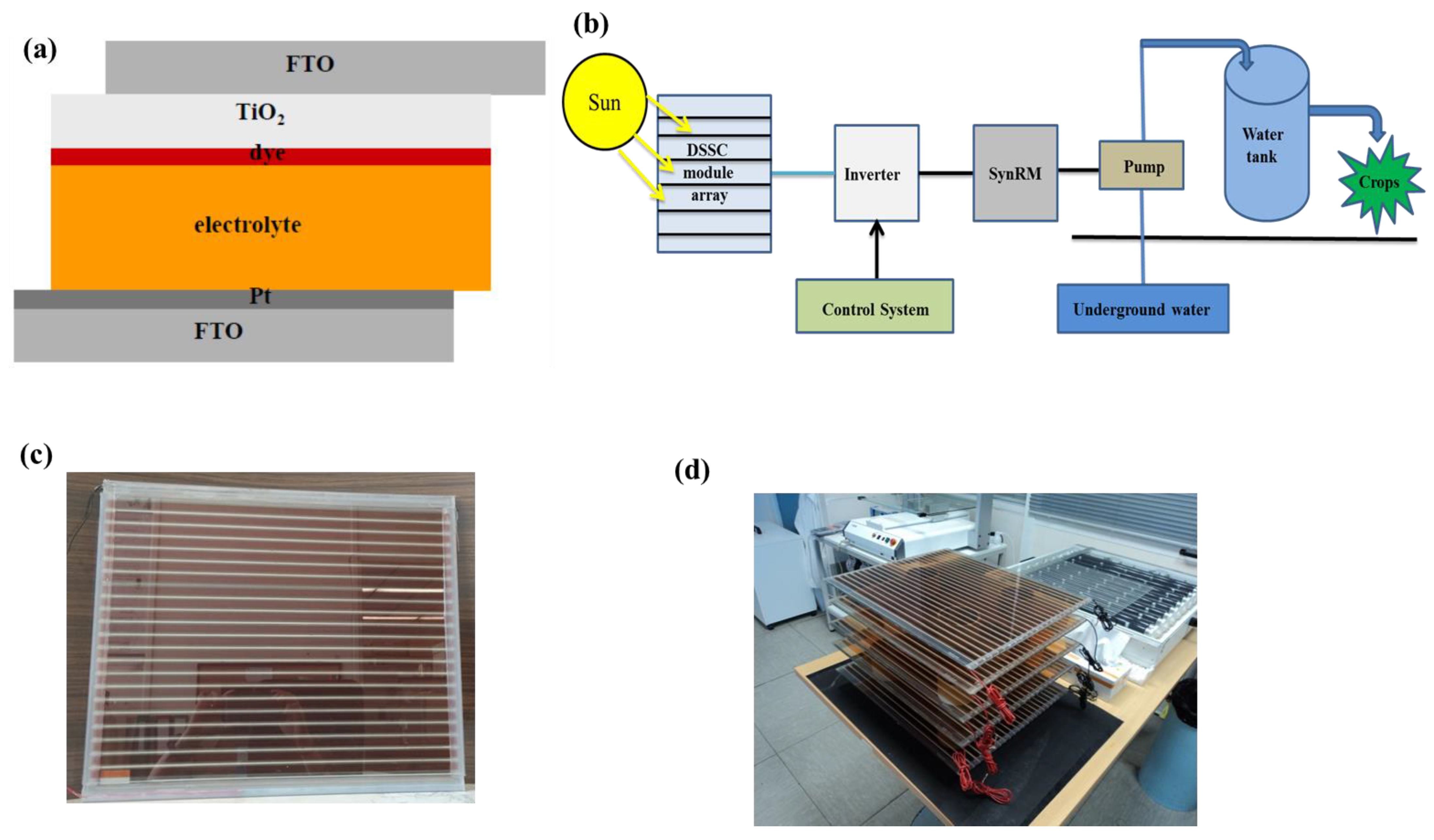
2.1. DSSC-Based Water-Pumping System Structure

Figure 1b displays the proposed system configuration and its components. It consists of a dye-sensitized solar (DSSC) module array, a conventional voltage source inverter (VSI) accompanied by a proposed control system, a three-phase SynRM, and a centrifugal pump. From Figure 1b, it is clear that there are no DC–DC converters and storage batteries in the proposed DSSC array water-pumping system, which helps to reduce the total cost.
The proposed (DSSC) module array, feeding the water-pumping system, can solve the problem of water availability for both human needs and crop irrigation in remote places that are situated far from the electric grid. The amount of water needed for crop irrigation or human use is governed by the population, the crop type, and the planted area. Thus, in the present study, a water-pumping application is considered, where the system produces an amount of 350 m3/day (with a daily average of 10 working hours). The height difference between the underground water and storage tank is 35 m, while the pump’s average flow rate is 35 m3/h. For the suggested application, the system parameters and the components of the proposed DSSC solar array feeding the water pump can be optimized and sized. The water pump power depends on both the water depth and the flow rate. The motor power is related to the pump power, and the DSSC module array design is determined by the power needed by the motor to drive the pump.

2.2. Modeling of the Proposed Water-Pumping System

2.2.1. DSSC Array

The array used in the proposed water-pumping system contains a number of DSSC modules connected in series and in parallel, as presented in Figure 1c,d. Each module has 22 series cells (purchased from Brite Solar S.A.). Figure 2a shows the single-diode model used to represent the DSSC device in this study for simulation purposes via the MATLAB toolbox. It is well known that the DSSC electrochemical impedance spectrum has three semicircular shapes, as indicated in Figure 2b, which represent the impedances corresponding to the charge transport at the counter electrode (Z1), the TiO2/dye/electrolyte interface (Z2), and the carrier transport by ions within the electrolyte (Z3), respectively. Each impedance has an a real part (resistance) and a capacitance element (C); the resistance in the high-frequency range is called Rh. The solar cells are always working under direct current conditions; thus, the capacitances can be neglected. As a result, R1, R3, and Rh are connected in series and can be represented by a resistance called the series resistance (Rs) of DSSCs. Figure 2c indicates the experimental setup employed for determining the DSSC module characteristics under varied operating conditions.
The DSSC modules were fabricated by Brite Solar S.A. using the screen printing technique, and N3 dye was used as the sensitizer.
The dye-sensitized solar cell output current can be expressed by Equation (1) [44,47]:
I P V = I p h I o [ exp ( V P V + R s I P V V t a ) 1 ] V P V + R s I P V R s h
where Ipv and Vpv indicate the PV current and voltage, respectively; Io and Iph represent the saturation and photo-current, respectively; Vt represents the thermal voltage; a denotes the diode ideality factor; Rs and Rsh indicate the series resistance and parallel resistance, respectively.
The DSSC array consists of series (Ns) and parallel (Np) modules. The output current of the array can be obtained from Equation (2) [41]:
I P V = I p h N p I o N p [ exp ( V P V + R s I P V ( N s N p ) V t a N s ) 1 ] V P V + R s I P V ( N s N p ) R s h ( N s N p )
The DSSC module and the complete array were characterized under different irradiation conditions. The current-voltage and power-voltage characteristic curves are displayed in Figure 3a,c, respectively. The MATLAB-simulated current-voltage and power-voltage characteristics of the designed DSSC array (with a total area of 17.67 m2) at different irradiation levels (e.g., G = 250, 500, 750, and 1000 W/m2) and T = 25 °C are shown in Figure 3b,d correspondingly. It is clear from Figure 3 that the array output depends on the irradiation level. The dye-sensitized solar array designed for this application consists of 93 total modules; 56 of them are connected in series, and the other 37 modules are connected in parallel. Each module has 22 individual cells (1 cm width × 45 cm length) in series; its dimension is 40 × 47.5 cm with the frame and 35 × 45 cm without the frame, while the active area is 52.5% of the module’s total surface (Figure 1c,d).
The DSSC module and the corresponding array parameters under full sun illumination are given in Table 1. The array power output is estimated to be 5.66 KW based on the requirements of other parts of the system. In this context, 93 DSSC modules, each one providing 1.66 W, as presented in Table 1, are used. In total, 56 DSSC modules are connected in series in order to supply the needed DC bus voltage (900 V), and 37 DSSC modules are arranged in parallel in order to deliver the required motor current (9 A).

2.2.2. Three-Phase Inverter Modeling

The inverter output voltage can be expressed by Equation (3). This voltage is the function of the DSSC module array’s output voltage (Vpv), which is also called the inverter input voltage (Vdc) [41]:
[ v a n v b n v c n ] = V p v 3 [ 2 1 1 1 2 1 1 1 2 ] [ g 1 g 2 g 3 ]
where Van, Vbn, and Vcn are output three-phase voltages. From Figure 4a, the inverter switching states, g1 to g3, are either 0 or 1; the 1 state means that the upper switch is on and the lower one is off and vice versa.

2.2.3. SynRM Modeling

SynRM modeling is performed based on the dq-axis rotor reference frame. From previous studies [44,47], Equation (4) represents the SynRM model [47]:
[ v d v q ] = [ R m 0 0 R m ] [ i d i q ] + [ t ω r P ω r P t ] [ λ d λ q ] T e = 3 2 P ( λ d i q λ q i d ) λ d = L d ( i d , i q ) i d λ q = L q ( i d , i q ) i q }
T e = J t d ω r d t + B ω r + T L
where (vd, vq) represent the voltage for the direct and quadrature axes, respectively; Rm denotes the stator phase resistance (0.4 ohm); (id, iq) are the current for the direct and quadrature axis, correspondingly; ωr is the rotor mechanical speed; p indicates the number of pole pairs, while (λd, λq) represent the flux linkage for the direct and quadrature axis components of the SynRM; Jt, B represent the moment of inertia (0.01 kg m2) and the viscous coefficient (0.0005 Ns m−2) of the system, respectively; and Te, TL denote the motor electrmagnetic torque and load torque, respectively.
From Equation (4), it is obvious that the SynRM performance is highly affected by the dq-axis flux linkages, which are influenced by the magnetic saturation behavior of the machine. As a consequence, there is a necessity for the machine magnetic saturation behavior, including in the model. Figure 4b,c show the magnetic saturation of the dq-axis flux linkages of the machine, which is obtained from lookup tables (LUTs) that were extracted from the finite element method toolbox (FEM). In FEM, the variation of id and iq current components is in a certain domain. This domain does not exceed twice the value of the rated current for achieving the needed analogy with the dq-axis flux linkage (ψd, ψq) components. This method is efficient for including magnetic saturation behavior in the SynRM. The geometrical variables of the SynRM are shown in Table 2.

2.2.4. Centrifugal Pump Modeling

The pump torque (Tpump), as a function of rotational speed (ωr), is presented in Equation (6) [46,48,49]:
T p u m p = k p ω r 2
where Kp is the pump proportionality constant that equals 1.76 × 10⁻⁴ N m/rad/s2, while ωr is the rotational speed in rad/s.

3. The Proposed Control System

The proposed control system for the dye-sensitized solar array water-pumping system is shown in Figure 4d.
Due to the fact that the SynRM is not a self-starting motor, a control system is required for the SynRM to work properly. As well known, a photovoltaic array requires a control system to work at a maximum power point for extracting the maximum available output power of the array. When the photovoltaic arrays work at the maximum power point, system efficiency increases and a lower number of photovoltaic modules are required, leading to a reduction in the system’s capital cost [50,51]. In this study, the SynRM was controlled efficiently for working at the maximum power per ampere, and DSSC array output power maximization (working at maximum power point) was implemented via the motor inverter. The perturb-and-observe maximum power point tracking technique is used in this study to maximize the DSSC array’s output power, while conventional field-oriented methodology is used to control the SynRM.

3.1. Field-Oriented Control (FOC) Technique

This methodology uses two reference signals, as illustrated in Figure 4d. The system power flow is controlled via the speed signal (ωr*), which is one of the two reference signals. The SynRM current is controlled via the second reference signal, which is the d-axis current signal (id*). As a result, the SynRM works properly at the maximum power per ampere. The maximum power point tracking methodology provides the speed reference single (ωr*), as shown in Figure 4d. Moreover, the second reference signal (d-axis current single (id*)) is extracted based on the FEM in LUT, which correlates the reference current signal (id*) and the motor torque. The trial-and-error principle was used for determining the PI controller’s parameters [44,47].

3.2. Maximum Power Point Tracing Technique

In this study, the DSSC array used for feeding the motor consists of a number of series and parallel modules in order to obtain the required power for motor driving. In order to get the maximum power output from the array, the maximum power point tracking technique is required.
The perturb-and-observe maximum power point tracing technique is proposed, as shown in Figure 4e. The maximum power point tracking technique provides the motor reference speed. The array voltage and current are measured, and the array output power is calculated. The array’s power and voltage at each time instant (t1) are compared with their previous values at time instant (t0). This comparison continues until the maximum power point is reached.

3.3. The Complete Proposed Pumping System Performance

The MATLAB toolbox was used in this study for operation validation and assessment via simulation. In this context, two different irradiation levels (500 and 1000 W/m2) were investigated, while the partial shading case was neglected thanks to the small area (17.67 m2) of the proposed modules. This is a very important advantage compared with conventional silicon solar cells, which need nearly 36 m2 as the required area for the same application. In order to drive the system properly, a proposed control system for maximum power point tracking for the DSSC module array and vector control methodology for the SynRM driving is proposed, as illustrated in Figure 4d. Figure 5 and Figure 6 show the performance of the proposed water-pumping system fed by the DSSC module array. The SynRM speed and torque behavior in the presence of the proposed control system are shown in Figure 5a,b, respectively. The results reveal how the SynRM speed successfully follows the reference speed obtained from the maximum power point tracking algorithm. Additionally, the motor succeeded in delivering the necessary load torque.
Figure 5c,d show the SynRM motor dq-axis current components. From these figures, it is clear that the SynRM currents match well the corresponding reference signals. It is well known that the d-axis current component varies based on the required load torque for ensuring a maximum torque per ampere condition, while the q-axis current component varies based on the reference speed for increasing SynRM power.
Figure 6a shows the output power extracted from the dye-sensitized solar array and the SynRM input power. It can be noticed that dye-sensitized solar array output is at the maximum point, thanks to the maximum power point tracking technique, as shown previously in Figure 4e. The SynRM power losses and efficiency are illustrated in Figure 6b,c, respectively. The performance results tell that SynRM efficiency is high, at the 500 W/m2 irradiation level, which represents a partial loading condition. Figure 6d shows the water pump flow rate in the proposed application. As a result, by using the proposed SynRM and dye-sensitized solar array, the whole-system efficiency will be high, resulting in energy production at a lower cost.

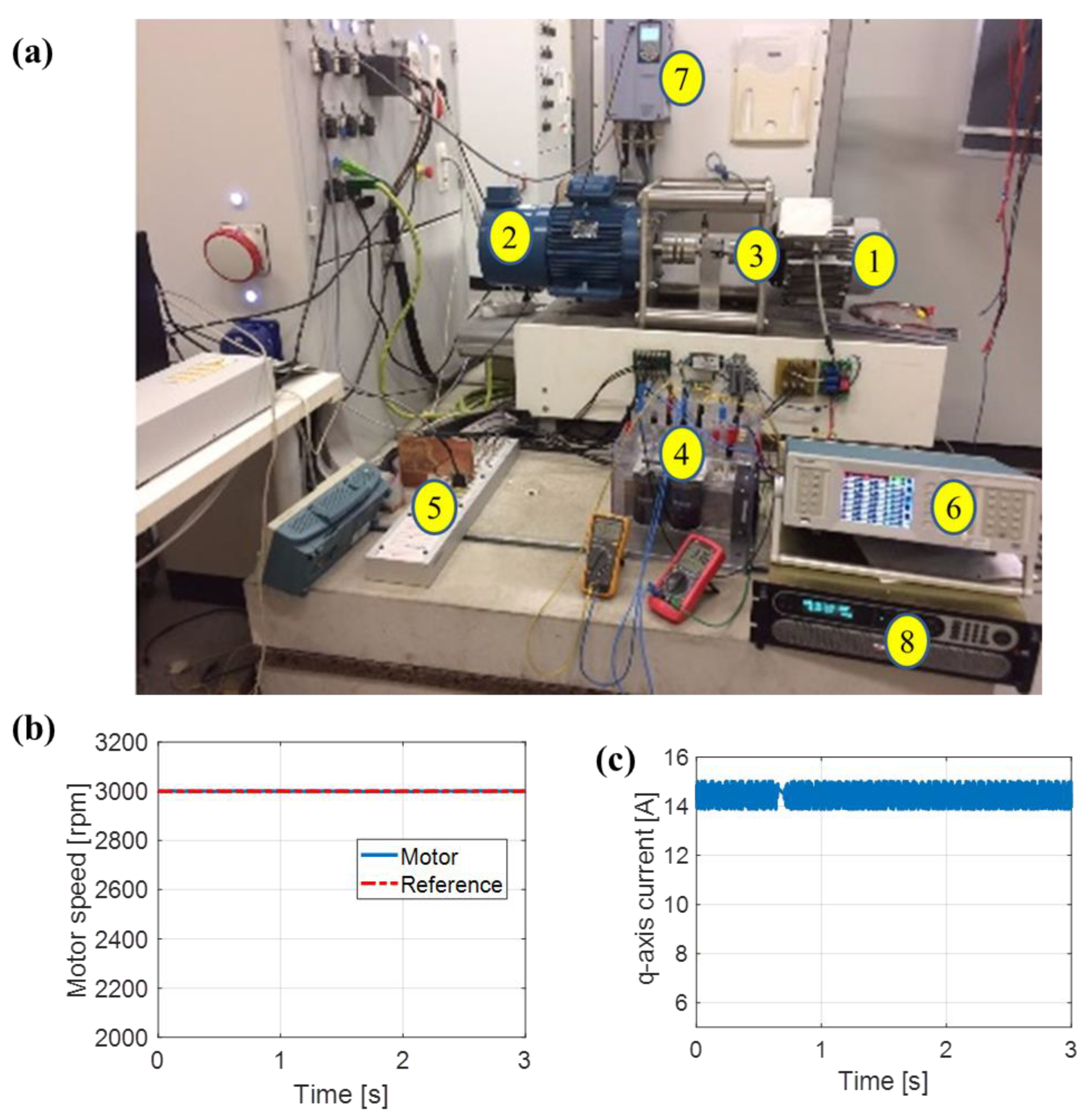
4. Experimental Confirmation

The presented work in this paper was validated via an experimental laboratory test bench, as illustrated in Figure 7a, to check the accuracy of the proposed system analysis. In the experimental model, a 5.5 kW SynRM (1) is connected with a 9.3 kW induction motor (2) via a torque sensor unit (3). A three-phase voltage source inverter (4) is used for driving the SynRM, while a DS1103 unit (5) is used for implementing the proposed control system, explained previously in Figure 8, for SynRM driving. Three identical current sensors (LA25-P) are used for measuring the SynRM currents, while the speed is measured via an incremental encoder of 1024 samples/revolution. The system’s electrical components (voltage, current, power factor) are measured via a power analyzer (6).
An induction motor controlled via a commercial drive (7) is used for emulating the pump loading conditions, while a controlled DC supply (8) is used to emulate the PV array.
A 3000 rpm motor-rated speed is given to the control system (Figure 7b) as a reference value, while the load torque is set at the rated value of the water pump. The reference current id* in the control system is determined from a lookup table generated from FEM based on the load torque for achieving the maximum torque per ampere condition for the SynRM. Figure 7b shows the comparison between the motor speed and the reference speed as a function of time. A comparison of the speeds reveals that the motor speed successfully follows the reference speed, without deviation. The SynRM dq-axis currents are presented in Figure 7c and Figure 8a. The d-axis current is set to reach the maximum torque per ampere case at different levels of load torque. From Figure 8b, it is understandable that the motor output power is sufficient for driving the load during the entire working time. These results validate the simulated results; moreover, a good match between the theoretical and experimental values is evident. Based on the experimental setup results, it is clear that the motor can successfully supply the load with the required torque.
Both measured and simulated power factors of the motor at different winding currents, up to the rated value, are shown in Figure 8c. The loading condition is represented by the winding current of the motor, where the rated load is, of course, at the rated current.
The efficiency map of the motor and the inverter for different loading levels, up to the rated value, are displayed in Figure 8d. The results show that the efficiency of the SynRM is always high enough, even at low loading conditions, leading to an increase in the whole PV system’s efficiency. From the above, it is evident that the proposed system’s simulated results are validated by the experimental results.

5. Conclusions

In this work, an efficient and low-cost photovoltaic water-pumping system based on a DSSC module array is recommended. The DSSC module uses the dye-sensitization approach as a fabrication technology. The DSSC module array was used for feeding a synchronous reluctance motor in the proposed water-pumping system. The proposed system was experimentally validated. The system modeling and analysis were done via a proposed methodology that used a motor inverter, which was derived from the proposed control system. The proposed methodology does not have a DC–DC converter or batteries, hence allowing the dye-sensitized solar array and the SynRM to work efficiently at maximum output energy and low cost.
The suggested DSSC module array water-pumping system has a lot of merits in comparison with other systems reported in the literature. The proposed system’s efficiency is high and its cost is low due to the use of the DSSC module array and the SynRM. In the proposed system, the required active surface for the DSSC array is 17.67 m2. This area is low in comparison to that of the 36 m2 required for a silicon solar array to power the same motor. This small size of the proposed DSSC module array leads to cost reduction and avoids partial shading problems, which usually badly affect the solar array’s performance and result in low efficiency and power instability.

Author Contributions

Conceptualization, A.A.Z.; methodology, A.A.Z.; software, A.A.Z.; validation, A.A.Z.; formal analysis, A.A.Z.; investigation, A.A.Z.; resources, A.A.Z.; data curation, A.A.Z.; writing—original draft preparation, A.A.Z.; writing—review and editing, A.A.Z. and M.N.I.; visualization, A.A.Z.; supervision, M.N.I., P.S., E.S. and P.F.; project administration, A.A.Z.; funding acquisition, M.N.I. All authors have read and agreed to the published version of the manuscript.

Funding

This work was supported by the European Regional Development Fund of the European Union and Greek national funds through the Operational Program Competitiveness, Entrepreneurship and Innovation, under the call RESEARCH–CREATE–INNOVATE (project code: T1EDK-03547, MIS 5033808).

Data Availability Statement

All data are contained within the article.

Conflicts of Interest

The authors have no financial/commercial conflicts of interest.

References

  1. Ahmed, U.; Alizadeh, M.; Rahim, N.A.; Shahabuddin, S.; Ahmed, M.S.; Pandey, A.K. A comprehensive review on counter electrodes for dye sensitized solar cells: A special focus on Pt-TCO free counter electrodes. Sol. Energy 2018, 174, 1097–1125. [Google Scholar] [CrossRef]
  2. Yoosuf, M.; Pradhan, S.C.; Soman, S.; Gopidas, K.R. Triple bond rigidified anthracene-triphenylamine sensitizers for dye-sensitized solar cells. Sol. Energy 2019, 188, 55–65. [Google Scholar] [CrossRef]
  3. Wu, H.; Xie, X.; Zhang, J.; Li, S.; Shen, Z.; Yuan, Y. Low-energy-gap organic photosensitizers with phenalenothiophene and benzoindenothiophene as primary electron-donors for durable dye-sensitized solar cells. J. Power Sources 2020, 451, 227748. [Google Scholar] [CrossRef]
  4. Abdellah, I.M.; El-Shafei, A. Synthesis and characterization of novel tetra anchoring A2-D-D-D-A2 architecture sensitizers for efficient dye-sensitized solar cell. Sol. Energy 2020, 198, 25–35. [Google Scholar] [CrossRef]
  5. Patil, S.S.; Mane, R.M.; Mali, S.S.; Hong, C.K.; Bhosale, P.N. Facile designing and assessment of photovoltaic performance of hydrothermally grown kesterite Cu2ZnSnS4 thin films: Influence of deposition time. Sol. Energy 2020, 201, 102–115. [Google Scholar] [CrossRef]
  6. Maddah, H.A.; Berry, V.; Behura, S.K. Biomolecular photosensitizers for dye-sensitized solar cells: Recent developments and critical insights. Renew. Sustain. Energy Rev. 2020, 121, 109678. [Google Scholar] [CrossRef]
  7. Duvva, N.; Chilakamarthi, U.; Giribabu, L. Recent developments in tetrathiafulvalene and dithiafulvalene based metal-free organic sensitizers for dye-sensitized solar cells: A mini-review. Sustain. Energy Fuels 2017, 1, 678–688. [Google Scholar] [CrossRef]
  8. Kumara, N.T.R.N.; Andery, L.; Chee Ming, L.; Iskandar, P.M.; Piyasiri, E. Recent progress and utilization of natural pigments in dye sensitized solar cells: A review. Renew. Sustain. Energy Rev. 2017, 78, 301–317. [Google Scholar]
  9. Repins, I.; Contreras, M.A.; Egaas, B.; DeHart, C.; Scharf, J.; Perkins, C.L.; To, B.; Noufi, R. 19·9%-efficient ZnO/CdS/CuInGaSe2 solar cell with 81·2% fill factor. Prog. Photovolt. Res. Appl. 2008, 16, 235–239. [Google Scholar] [CrossRef] [Green Version]
  10. Yoo, J.J.; Wieghold, S.; Sponseller, M.C.; Chua, M.R.; Bertram, S.N.; Hartono, N.T.P.; Tresback, J.S.; Hansen, E.C.; Correa-Baena, J.P.; Bulovic´, V.; et al. An interface stabilized perovskite solar cell with high stabilized efficiency and low voltage loss. Energy Environ. Sci. 2019, 12, 2192–2199. [Google Scholar] [CrossRef] [Green Version]
  11. Ren, H.; Yu, S.; Chao, L.; Xia, Y.; Sun, Y.; Zuo, S.; Li, F.; Niu, T.; Yang, Y.; Ju, H.; et al. Efficient and stable Ruddlesden–Popper perovskite solar cell with tailored interlayer molecular interaction Nat. Photonics 2020, 14, 154–163. [Google Scholar] [CrossRef]
  12. Zhou, L.; Chang, J.; Liu, Z.; Sun, X.; Lin, Z.; Chen, D.; Zhang, C.; Zhang, J.; Hao, Y. Enhanced planar perovskite solar cell efficiency and stability using a perovskite/PCBM heterojunction formed in one step. Nanoscale 2018, 10, 3053–3059. [Google Scholar] [CrossRef] [PubMed]
  13. Regan, B.O.; Gratzelt, M. A low-cost, high-efficiency solar cell based on dye-sensitized colloidal TiO2 films. Nature 1991, 353, 737–740. [Google Scholar] [CrossRef]
  14. Balis, N.; Zaky, A.A.; Perganti, D.; Kaltzoglou, A.; Sygellou, L.; Katsaros, F.; Stergiopoulos, T.; Kontos, A.G.; Falaras, P. Dye Sensitization of Titania Compact Layer for Efficient and Stable Perovskite Solar Cells. ACS Appl. Energy Mater. 2018, 1, 6161–6171. [Google Scholar]
  15. Zaky, A.A.; Christopoulos, E.; Gkini, K.; Arfanis, M.K.; Sygellou, L.; Kaltzoglou, A.; Stergiou, A.; Tagmatarchis, N.; Balis, N.; Falaras, P. Enhancing efficiency and decreasing photocatalytic degradation of perovskite solar cells using a hydrophobic copper-modified titania electron transport layer. Appl. Catal. B Environ. 2021, 284, 119714. [Google Scholar] [CrossRef]
  16. Zaky, A.A.; Balis, N.; Gkini, K.; Athanasekou, C.; Kaltzoglou, A.; Stergiopoulos, T.; Falaras, P. Dye Engineered Perovskite SolarCells under Accelerated Thermal Stress and Prolonged Light Exposure. ChemistrySelect 2020, 5, 4454–4462. [Google Scholar] [CrossRef]
  17. Jiang, M.L.; Wen, J.J.; Chen, Z.M.; Tsai, W.H.; Lin, T.C.; Chow, T.J.; Chang, Y.J. High-Performance Organic Dyes with Electron-Deficient Quinoxalinoid Heterocycles for Dye-Sensitized Solar Cells under One Sun and Indoor Light. Chem. Sus. Chem. 2019, 12, 3654. [Google Scholar] [CrossRef]
  18. Bramhankar, T.S.; Pawar, S.S.; Shaikh, J.S.; Gunge, V.C.; Beedri, N.I.; Baviskar, P.K.; Pathan, H.M.; Patil, P.S.; Kambale, R.C.; Pawar, R.S. Effect of Nickel–Zinc Co-doped TiO2 blocking layer on performance of DSSCs. J. Alloys Compd. 2020, 817, 152810. [Google Scholar] [CrossRef]
  19. Aslam, A.; Mehmood, U.; Arshad, M.H.; Ishfaq, A.; Zaheer, J.; Haq Khan, A.U.; Sufyan, M. Dye-sensitized solar cells (DSSCs) as a potential photovoltaic technology for the self-powered internet of things (IoTs) applications. Sol. Energy 2020, 207, 874–892. [Google Scholar] [CrossRef]
  20. Falaras, P.; Stergiopoulos, T.; Tsoukleris, D.S. Enhanced efficiency in solid-state dye sensitized solar cells based on fractal nanostructured TiO2 thin films prepared via sol-gel process in polymer matrix. Small 2008, 4, 770–776. [Google Scholar] [CrossRef]
  21. Falaras, P.; Likodimos, V.; Stergiopoulos, T.; Harikisun, R.; Desilvestro, J.; Tulloch, G. Prolonged light and thermal stress effects on industrial dye-sensitized solar cells: A micro-Raman investigation on the long term stability of aged cells. J. Phys. Chem. C 2009, 113, 9412–9422. [Google Scholar]
  22. Vougioukalakis, G.C.; Philippopoulos, A.I.; Stergiopoulos, T.; Falaras, P. Contributions to the development of ruthenium-based sensitizers for dye-sensitized solar cells. Coord. Chem. Rev. 2011, 255, 2602–2621. [Google Scholar] [CrossRef]
  23. Stergiopoulos, T.; Bidikoudi, M.; Likodimos, V.; Falaras, P. Dye-sensitized solar cells incorporating novel Co(II/III) based-redox electrolytes solidified by silica nanoparticles. J. Mater. Chem. 2012, 22, 24430–24438. [Google Scholar] [CrossRef]
  24. Vaenas, N.; Bidikoudi, M.; Stergiopoulos, T.; Likodimos, V.; Kontos, A.G.; Falaras, P. Annealing effects on self-assembled TiO2 nanotubes and their behaviour as photoelectrodes in dye-sensitized solar cells. Chem. Eng. J. 2013, 224, 121–127. [Google Scholar] [CrossRef]
  25. Stergiopoulos, T.; Konstantakou, M.; Falaras, P. Dye solar cells combining TiO2 surface-blocking organic sensitizer and solvent-free ionic liquid-based redox electrolyte. RSC Adv. 2013, 3, 15014–15021. [Google Scholar] [CrossRef]
  26. Bidikoudi, M.; Stergiopoulos, T.; Likodimos, V.; Romanos, G.E.; Francisco Iliev, B.; Gabriela, A.; Schubert, T.; Falaras, P. Ionic liquid redox electrolytes based on binary mixtures of 1-alkyl-methylimidazolium tricyanomethanide with 1-methyl-3-propylimidazolium iodide and implication in dye-sensitized solar cells. J. Mater. Chem. A 2013, 1, 10474–10486. [Google Scholar] [CrossRef] [Green Version]
  27. Bidikoudi, M.; Zubeir, L.F.; Falaras, P. Low viscosity highly conductive ionic liquid blends for redox active electrolytes in efficient dye-sensitized solar cells. J. Mater. Chem. A 2014, 2, 15326–15336. [Google Scholar] [CrossRef]
  28. Perganti, D.; Giannouri, M.; Kontos, A.G.; Falaras, P. Cost-efficient platinum-free DSCs using colloidal graphite counter electrodes combined with D35 organic dye and cobalt (II/III) redox couple. Electrochim. Acta 2017, 2, 517–527. [Google Scholar] [CrossRef]
  29. Chandel, S.S.; Naik, M.N.; Chandel, R. Review of solar photovoltaic water pumping system technology for irrigation and community drinking water supplies. Renew Sustain. Energy Rev. 2015, 49, 1084–1099. [Google Scholar] [CrossRef]
  30. Rezkallah, M.; Chandra, A.; Tremblay, M.; Ibrahim, H. Experimental implementation of an APC with enhanced MPPT for standalone solar photovoltaic based water pumping station. IEEE Trans. Sustain. Energy 2019, 10, 181–191. [Google Scholar] [CrossRef]
  31. Kolhe, M.; Joshi, J.C.; DKothari, D.P. Performance analysis of a directly coupled photovoltaic water-pumping system. IEEE Trans. Energy Convers. 2004, 19, 613–618. [Google Scholar] [CrossRef]
  32. Caracas, J.V.M.; Farias, G.D.C.; Teixeira, L.F.M.; Ribeiro, L.A.D.S. Implementation of a high-efficiency high-lifetime and low-cost converter for an autonomous photovoltaic water pumping system. IEEE Trans. Ind. Appl. 2014, 50, 631–641. [Google Scholar] [CrossRef]
  33. Elgendy, M.A.; Zahawi, B.; Atkinson, D.J. Comparison of directly connected and constant voltage controlled photovoltaic pumping systems. IEEE Trans. Sustain. Energy 2010, 1, 184–192. [Google Scholar] [CrossRef]
  34. Jain, S.; Thopukara, A.K.; Karampuri, R.; Somasekhar, V.T. A single-stage photovoltaic system for a dual-inverter-fed open end winding induction motor drive for pumping applications. IEEE Trans. Power Electron. 2015, 30, 4809–4818. [Google Scholar] [CrossRef]
  35. Youssef, M.Z. Design and performance of a cost-effective BLDC drive for water pump application. IEEE Trans. Ind. Electron. 2015, 62, 3277–3284. [Google Scholar] [CrossRef]
  36. Sharma, P.; Lee, J.H.; Sul, S.K. New maximum power extraction algorithm for single stage solar water pump system working effectively for dynamically changing conditions. In Proceedings of the IEEE International Conference on Power Electronics, Drives and Energy Systems, Trivandrum, India, 14–17 December 2016; pp. 1–6. [Google Scholar]
  37. Narayana, V.; Mishra, A.K.; Singh, B. Design of SRM driven BESS based PV powered water pumping system. In Proceedings of the 7th Power India International Conference, (PIICON), Bikaner, India, 25–27 November 2016; p. 16. [Google Scholar]
  38. Murshid, S.; Singh, B. A PV array fed BESS supported speed sensor-less PMSM driven water pumping system. In Proceedings of the IEEE Transportation Electrification Conference and Expo, (ITEC), Long Beach, CA, USA, 13–15 June 2018; pp. 63–68. [Google Scholar]
  39. Kumar, R.; Singh, B. Grid interfaced solar PV powered brushless DC motor driven water pumping system. In Proceedings of the 7th India International Conference on Power Electronics, Patiala, India, 17–19 November 2016; pp. 1–5. [Google Scholar]
  40. Mahmoud, E.; el Nather, H. Renewable energy and sustainable developments in Egypt: Photovoltaic water pumping in remote areas. Appl. Energy. 2003, 74, 141–147. [Google Scholar] [CrossRef]
  41. Ibrahim, M.N.; Rezk, H.; Al-Dahifallah, M.; Sergeant, P. Hybrid photovoltaic-thermoelectric generator powered synchronous reluctance motor for pumping applications. IEEE Access. 2019, 7, 146979–146988. [Google Scholar] [CrossRef]
  42. Yang, Z.; Shang, F.; Brown, I.P.; Krishnamurthy, M. Comparative study of interior permanent magnet, induction, and switched reluctance motor drives for EV and HEV applications. IEEE Trans. Transp. Electric. 2015, 1, 245–254. [Google Scholar] [CrossRef]
  43. Kumar, R.; Singh, B. BLDC motor-driven solar PV array-fed water pumping system employing zeta converter. IEEE Trans. Ind. Appl. 2016, 52, 2315–2322. [Google Scholar] [CrossRef]
  44. Ibrahim, M.N. Design Aspects of High Performance Synchronous Reluctance Machines with and without Permanent Magnets. Doctoral Thesis, Ghent University, Ghent, Belgium, 2017. [Google Scholar]
  45. Ibrahim, M.N.; Rezk, H.; Al-Dhaifallah, M.; Sergeant, P. Solar array fed synchronous reluctance motor driven water pump: An improved performance under partial shading conditions. IEEE Access 2019, 7, 77100–77115. [Google Scholar] [CrossRef]
  46. Nabil, M.; Allam, S.M.; Rashad, E.M. Modeling and design considerations of a photovoltaic energy source feeding a synchronous reluctance motor suitable for pumping systems. Ain Shams Eng. J. 2012, 3, 375–382. [Google Scholar] [CrossRef] [Green Version]
  47. Ibrahim, M.N.; Rezk, H.; Al-Dhaifallah, M.; Sergeant, P. Modelling and Design Methodology of an Improved Performance Photovoltaic Pumping System Employing Ferrite Magnet Synchronous Reluctance Motors. Mathematics 2020, 8, 1429. [Google Scholar] [CrossRef]
  48. Hamza, A.A.; Taha, A.Z. Performance of submersible PV solar pumping systems under conditions in the Sudan. Renew. Energy 1995, 6, 491–495. [Google Scholar] [CrossRef]
  49. Hamidat, A.; Benyoucef, B.; Hartani, T. Small-scale irrigation with photovoltaic water pumping system in Sahara regions. Renew. Energy 2003, 28, 1081–1096. [Google Scholar] [CrossRef]
  50. Rezk, H.; Eltamaly, A.M. A comprehensive comparison of different MPPT techniques for photovoltaic systems. Sol. Energy 2015, 112, 1–11. [Google Scholar] [CrossRef]
  51. Ibrahim, M.N.; Sergeant, P.; Rashad, E.M. Design of low cost and efficient photovoltaic pumping system utilizing synchronous reluctance motor. In Proceedings of the IEEE International Electric Machines and Drives Conference (IEMDC), Miami, FL, USA, 21–24 May 2017; pp. 1–7. [Google Scholar]
Figure 1. DSSC structure: FTO/TiO2/dye/electrolyte/Pt/FTO (FTO: fluorine-doped tin oxide on glass) (a); schematic representation of the water-pumping system fed by a DSSC module array (b); DSCS module (40 × 47.5 cm) consisting of 22 unit cells (1 × 45 cm) connecting in series (c); and the package of modules employed for the construction of the DSSC array (d).
Machines 10 00882 g001
Figure 2. Single-diode model simulating the DSSC operation (a); DSSC electrochemical impedance spectrum (b); experimental setup (c).
Machines 10 00882 g002
Figure 3. The DSSC module’s (a,c) and the designed array’s (b,d) characteristics (current and power) at different irradiation levels.
Machines 10 00882 g003
Figure 4. The voltage source inverter (VSI) model (a); SynRM axis flux linkage components against the current components (b,c); schematic diagram of the complete proposed system (d); the perturb-and-observe maximum power point tracing technique (e).
Machines 10 00882 g004
Figure 5. (a) SynRM speed versus time; (b) SynRM torque versus time; (c) SynRM d-axis current versus time; (d) SynRM q-axis current versus time.
Machines 10 00882 g005
Figure 6. (a) The PV array output power and the motor input power versus time. SynRM q-axis current versus time. (b) SynRM motor power losses versus time. (c) SynRM efficiency versus time. (d) The pump flow rate versus time.
Machines 10 00882 g006
Figure 7. Experimental test bench (a); reference and motor speeds (b); q-axis current (c).
Machines 10 00882 g007
Figure 8. The d-axis current of the SynRM at the rated condition (a); power of the motor and pump at the rated condition (b); measured motor power factor at different currents (c); measured efficiency map of the whole drive system (motor + inverter) (d).
Machines 10 00882 g008
Table 1. The dye-sensitized solar module and array specifications.
ModuleArray
Number of Cells222046
Short Circuit Current (Isc)0.248 A9.18 A
Maximum Power Current (Imp)0.156 A8.462 A
Open Circuit Voltage (Voc)16.23 (V)908.89 (V)
Maximum Power Voltage (Vmp)10.62 (V)676.8 (V)
Maximum Power1.66 (W)5727 (W)
Area0.19 m217.67 m2
Table 2. SynRM geometrical variables.
RatingsStator Parameters
Voltage380 VSlots/poles36/4Shaft diameter/outer diameter35 mm/109.4 mm
Current12.23 AStator steel typeM270-50ARotor steel typeM330-50A/
Power5.5 kWPhases number3Flux barriers/pole3
Speed3000 RPMdiameter (outer/inner)180 mm/110 mmStack length/air gab length140 mm/0.3 mm
Publisher’s Note: MDPI stays neutral with regard to jurisdictional claims in published maps and institutional affiliations.

