
Mineralogical Characteristics and Preliminary Beneficiation of Nickel Slag from Reduction Roasting-Ammonia Leaching

Peace Buliding, Main Campus of Central South University, Changsha 410083, China
*
Authors to whom correspondence should be addressed.
Minerals 2017, 7(6), 98; https://doi.org/10.3390/min7060098
Submission received: 13 May 2017
/
Revised: 3 June 2017
/
Accepted: 6 June 2017
/
Published: 9 June 2017
Abstract
:The reduction roasting ammonia leaching process (RRAL) originally defined by Caron (1950) has been extensively applied to treat low grade nickel laterite and a large amount of slag-containing some valuable metals, has been generated and accumulated over the years since then. However, there are no reports on how to utilize it based on its essential properties. In this investigation, the textural and mineralogical characterization of the typical nickel slag from RRAL in Western Australia was performed by X-ray diffraction (XRD), and scanning electron microscopy with energy dispersive spectroscopy (SEM-EDS). The results show that the nickel slag is dominated by magnetite, maghemite, gangue minerals and minor Cr-spinel. The magnetite and maghemite possess simple distribution relationship with other minerals and their particles are highly variable with most over 50 μm, which are easily able to be recovered. In term of the complex association and distribution feature of chromium and nickel minerals, it is very difficult to recovery them. Meanwhile, an economically viable extraction process was proposed to preliminarily utilize the nickel slag based on textural and mineralogical characteristics of the slag, and the magnetic concentrate, assaying about 62% iron grade at over 75% recovery rate, was obtained through the recommended method.

1. Introduction
Nickel laterite is an important nickel oxide ore, which accounts for about 60–70% of the world’s land-based nickel reserves [1,2,3]. It is estimated that approximately 40% of the current worldwide nickel production is derived from nickel laterite. Meanwhile, strong demand for nickel in recent years and depletion of high grade ores have prompted the need to process more these low grade reserves of laterite [4,5]. Unfortunately, the nickel laterite is very difficult to treat due to its low-grade and complex mineralogy.
Collectively, these provided much impetus to develop mature technologies to recover nickel from laterite ores. Hydrometallurgical processes, as the effective technologies, are preferred to extract the nickel from limonitic laterite which is a principal nickel-bearing ore [6,7,8]. Therein, reduction roasting-ammonia leaching (RRAL) is one of mature technologies to process the limonitic laterite and has been extensively used in industrial applications for decades [9,10,11,12]. Until now, this process is commercially used in several countries, including Cuba, Australia and Philippines [9]. This process just focuses on how to improve the utilization of nickel and associated cobalt, and lots of other valuable metals (Fe, Cr) are neglected and discarded into waste slag [9]. Undoubtedly, a large amount of slag had been inevitably generated and accumulated from this process. Dumping or disposal of the slag not only wastes valuable resources (Fe, Cr, Ni) contained within it, but also potentially causes severe damages to the ecological environment, such as heavy metal pollution, surrounding soils and watercourses problem. Hence, it is extremely urgent to develop appropriate technology to comprehensively utilize the slag. In the reduction roasting-ammonia leaching process, various metal oxide minerals within nickel laterite were reduced by coal at 600–900 °C first. Minerals always tend to undergo phase transformation during reduction roasting, and they will not change much in leaching stage [5,10]. Generally, similar to other non-ferrous metal slag, the processes extracting the valuable metals primarily include acid leaching to recover the Ni and Co [13,14], roasting followed by leaching [15], reduction or direct reduction-wet magnetic separation process to recycle Fe and Cr [16,17,18], and flocculation-magnetic separation to recover iron as magnetite [19,20,21]. Nonetheless, distribution characteristics and the chemical and mineral compositions of the slag from different processes can vary significantly, and thus, different utilization options should be applied. Hence, the properties of slag obtained from that should be primarily carried out in order to the better utilization of slag.
However, few studies have been carried out on the characteristics and associations of valuable metals within nickel slag so far [9,22]. In the paper, a kind of typical nickel slag samples obtained from RRAL in western Australia were used to determine its chemistry, the distribution, morphology and textures of the various mineral phases, in particular those with related elements of economic interest by using X-ray fluorescence spectroscopy, X-ray diffraction, optical microscopy and environmental scanning electron microscopy. Based on above results, a reasonable strategy of utilizing the nickel slag was briefly proposed.
2. Materials and Methods
2.1. Materials
The nickel slag used in the study was collected from Western Australia. Its chemical composition measured by XRF is presented in Table 1. The results indicate that the iron grade is 37.86%, which is higher than the average iron grade of iron ores (32% Fe) in China. Iron, as the main element within the slag, has high value for recovery. Meanwhile, the contents of Ni and Cr2O3 are 0.32% and 5.57%, respectively.
The size distributions of nickel slag and the fraction of Fe, SiO2 and Al2O3 in different sizes are shown in Figure 1. As can be seen from that, the samples possess the fineness of approximately 60% passing 0.074 mm, and above 95% passing 0.5 mm, which is beneficial to reduce the cost of grinding the load. In addition, the fraction of iron distributing in coarse size is low whereas the gangue minerals, such as SiO2 and Al2O3, are mainly present in the size of above 0.074 mm. Thus, it is essential to upgrade the slag by regrinding and re-concentration process.
2.2. Methods
2.2.1. Methodology of Mineralogy Characteristics
In this study, a suite of specimens has been collected and subjected to a diversity of analytical techniques. XRD analysis was conducted on an X’Pert PRO MPD instrument (Cu Kα, 40 mA current, 40 kV voltage) to determine the crystalline phases of nickel slag. The mineral phases of nickel slag were investigated by chemical analysis according to “DZG20.01-1991”. The scanning electron microscope (SEM) was used to identify mineral phases and to detect their chemistry, as well as textural relationships. SEM images were recorded in backscatter electron modes operating in low vacuum mode at 0.5 Torr and 20 keV. The phase compositions of interest section and particle diameter were measured by SEM combined with an energy dispersive spectrometer (EDS) microanalysis system (JEOL, Tokyo, Japan). Microstructures of slag were performed by Leica DMLP optical microscopy, FEI Quata-200 scanning electron microscope and EDAX32 genesis spectrometer.
2.2.2. Magnetic Separation
In view of the embedded features of the magnetite and maghemite minerals, the stage grinding-stage low intensity magnetic separation process was adopted to upgrade the nickel slag.
First stage: Firstly, a 50 g batch of sample was mixed with 50 mL of water and ground in a small stainless steel ball mill (model: XMQ240 × 90). The grinding fineness was controlled by adjusting the grinding time. Secondly, the mix slurry was dressed by wet magnetic separation for 10 min in an XCGS-73 Davis Magnetic Tube at the fixed magnetic field strength. The products were dried at 75 °C in a vacuum oven for 2 h. After that, the compositions of both dry magnetic and non-magnetic products were analyzed using chemical methods.
Second stage: The grinding and magnetic separation processes is the same with the first stage. However, the materials were obtained from first stage at optimum conditions. Before the mix slurry was subjected by magnetic separation, the required amount of disperse agent was added in it.
The reduction results were assessed by iron grade of magnetic products and iron recovery of the magnetic separation process, and those indexes were calculated as follows:
Iron recovery of magnetic separation
where ε is iron recovery of magnetic separation; TFe1 is total iron grade of raw materials; TFe2 is total iron grade of magnetic product; m1 is the mass of dried raw material feeding for magnetic separation; m2 is the mass of dried magnetic product of magnetic separation.
2.2.3. Phase Characterization
The chemical phase of iron was analyzed by selective separation according to the methods [23,24], and the flowsheet is shown in Figure 2.
As can be seen from the above, it is worth noting that the magnetic part is a mixture of magnetic (Fe3O4) and maghemite (r-Fe2O3). The content of FeO was measured by chemical titration method [25], which all come from magnetic (Fe3O4). Therefore, the content of magnetic and maghemite can be calculated by Equations (2) and (3), respectively.
where is content of maghemite in magnetic part; is content of magnetite in magnetic part; is total iron content of magnetic part; is content of FeO in magnetic part.
2.2.4. Thermomechanical Analysis
Gibbs free energy change (∆G) with temperature was calculated through reaction equation module of HSC 5.1. The equilibrium phase compositions for reduction of cobalt oxide, nickel oxide and iron oxides at various PCO/PCO+CO2 and temperatures were studied by equilibrium composition module of HSC 5.1. Binary phase diagram of Fe-Ni was obtained by FactSage 7.0.
3. Results and Discussion
3.1. Phase Compositions of Nickel Slag
The XRD pattern of the nickel slag is shown in Figure 3. It can be seen that magnetite, fayalite and quartz are the dominant phases in nickel slag. Fayalite maybe formed according to the reactions between FeO, MgO and SiO2 during reduction process of laterite concentrate before ammonia leaching, which cannot be recovered using physical separation processes.
3.2. Occurrence of Valuable Metals
3.2.1. Iron Minerals
The mineral phases of iron in slag are listed in Table 2. Iron mainly exists in the form of magnetite accounting for 75.75% total iron content, which can be enriched by traditional magnetic separation process. In addition, maghemite (γ-Fe2O3), given the similar spinel structure with magnetite and possessing high magnetism, was also determined in the slag and its mineral fraction is as high as 12.49%. Therefore, the maximum recovery of iron in low intensity magnetic separation can reach above 85% theoretically.
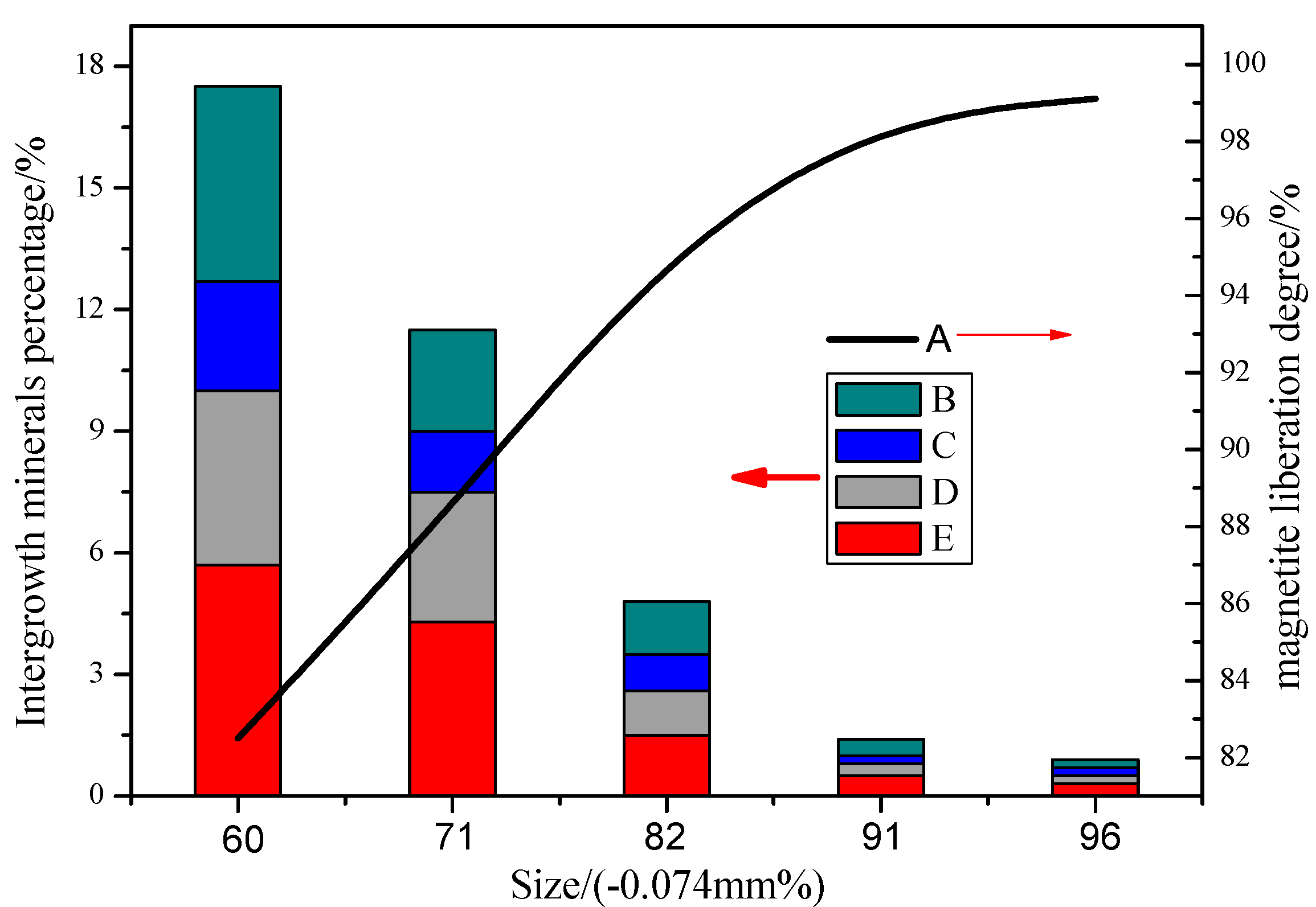
Magnetite, as the predominant iron-bearing mineral, is primarily considered to be enriched by magnetic separation, and its liberation degree in the nickel slag with different ground sizes was calculated by the horizon method, as shown in Figure 4. As can be seen from that, the magnetite liberation degree was increased significantly with the size reduction. When the sample was ground to the fineness of 93% below 0.074 mm, the liberation degree reached 98.6%.
Generally, liberation has been recognized as an important performance indicator since the degree of liberation of valuable minerals dictates the theoretically achievable grade-recovery curve for downstream separation processes [26,27]. In order to attain the high recovery rate and concentrate grade, the valuable minerals should be fully disintegrated. In terms of the nickel slag, the grinding fineness should be ensured as 91% passing 0.074 mm.
As seen in Table 2, the iron is mainly present in magnetite and maghemite, and their photomicrographs are shown in Figure 5. The occurrence of magnetite in the slag is not very complicated, it was deemed appropriate to simplify the shape characterization for the remainder of the study by classifying all magnetite particles into three categories: The single magnetite, tended to be concentrated in a large proportion of the slag and to retain well crystalline structures, has a relatively coarse grain size and seems very pure, which is in favor of mineral liberation in milling; the disseminated magnetite, is notably associated with hard matrix minerals and is intimately associated with gangue minerals (serpentine, silicate, fayalite), often tending to distribute in the shapes of blocks; the minor magnetite, crystallized insufficiently, is very dispersive and fine, and is closely surrounded by the other minerals. They present in the form of a fishbone with most of less than 5 μm, which is difficult to recover despite of fine grinding [27].
Fortunately, the proportion of minor magnetite in all magnetite minerals is very little, only about 5%. SEM back-scattered electron images of the section, as shown in Figure 6, further confirm that the minor magnetite has complex association and distribution with the other minerals and possesses the very fine grain size.
Maghemite appears much fewer frequencies in the slag than that of magnetite, which is present in the form of various shapes, such as thin strips, graininess, bead or flat. Some of them have a similar form with magnetite, being generated possibly from the transformations of magnetite. In addition, some iron is held in argillite, which is a mixture, including some Si and Al and is formed through strong weathering. It is poorly crystallized and possess incompact structure. Hence, this mixture in slag is very apt to be slimed so as to produce a large amount of secondary slime in the milling process which can adversely affect the iron recovery and grade in magnetic separation, that is because of mechanic inclusion [28,29].
As such, despite the textural variability and diversity of iron-bearing minerals in the nickel slag, it is believed that magnetite and maghemite are the target minerals to recover due to their relatively high liberation degree and accounting for a high proportion in total iron minerals.
3.2.2. Chromium Minerals
The picotite is the predominant Cr-bearing mineral and its textures are shown in Figure 7. The majority of the picotites occur as isolated individual grains while they are either entrapped within the gangue minerals as belt shapes or are present as liberated free crystals. Moreover, the picotite grains exhibited perfect euhedral-subhedral shaped crystals that are conglomerated to form particles with different sizes of 30–120 μm and shapes like the polygon, trigon and cube structures. In the light of the embedded features, it seems that the picotite has simple association and distribution with other minerals, which is beneficial to liberation and physical separation.
However, chemical composition of the picotite is very complicated. Chemical composition and elements distribution characteristics of minerals were determined by spot analysis using an energy dispersive spectrometer (EDS), the results are shown in Figure 8 and Figure 9, and Table 3. The surface scanning images, presenting the similar distribution of Cr, Fe, Al and Mg, show that some Al3+ and Mg2+ cations substitute Cr3+ cations to form the solid solution. EDS results of picotites indicate that the Cr2O3 contents of picotites vary from 38.83 to 52.62 wt % (averaging 47.35 wt %) and Al2O3 contents from 14.77 to 28.51 wt % (averaging 20.39 wt %). MgO and FeO contents vary from 9.26 to 14.70 wt % (averaging 12.21 wt %) and 15.97 to 20.96 wt % (averaging 17.50 wt %), respectively. Meanwhile, some trace elements, such as Si, Ca, were likewise detected in the picotite minerals. It can be inferred from the compositional data that the primary picotites in the slag more often have (Cr, Fe, Al)xOy precipitates. However, the presence of substituting metal ions (Mg2+ and Al3+) in the Cr-bearing minerals will correspond low recovery values due to poor enrichment effect by physical separation processes.
3.2.3. Nickel Minerals
In the reduction roasting-ammonia leaching process, various metal oxide minerals within nickel laterite were reduced by coal and the possible reactions are shown as follows:
The standard Gibbs free energy of above reactions was calculated and the results are shown in Figure 10. It is clear that the standard Gibbs free energy of reactions is negative under the normal reduction temperature (750–950 °C), which implies that NiO, CoO, Fe2O3 and Fe3O4 can be easily reduced by CO, and simultaneously the preferential reduction of nickel oxide and cobalt oxide followed by iron oxide takes place.
Generally, it is anticipated that the generation of metallic nickel and cobalt should be maximized as much as possible whereas the reduction of the iron oxide has to be restricted to the formation of magnetite in the reduction process [30,31,32,33]. However, it is inevitable that part of magnetite and wustite was further reduced to metallic iron under the experiment conditions. Moreover, metallic iron has a high affinity with metallic nickel to form a solid solution with Ni of a limited solubility, namely Fe-Ni (Fe-Ni-Co) alloy (as shown in Figure 11), which lead to low recoveries of Ni and Co in subsequent leaching process.
Figure 12 shows the SEM image and EDS elemental maps of Ni-bearing minerals in nickel slag. It is clear from the observations throughout the area that the residual nickels within the nickel slag were trapped in magnetite minerals as the form of prill, which have extremely small lower than 5 μm.
The EDS pattern of the prill shows that the nickel-bearing minerals are dominated by Fe and Ni, as well the cobalt replacing some nickel elements as solid solution. Based on thermodynamics analysis and SEM-EDS results, it is inferred that the residual nickel in the slag is present as the form of Fe-Ni alloy.
Although the Fe-Ni alloy in the nickel slag may contribute to the value of the slag, the very fine grain size is expected to show a poor recovery, and in terms of their extremely close association with magnetite, it is not considered for extraction solely and may be mingled with magnetic products in magnetic separation process, resulting in compromise the quality of magnetite concentrates [34].
3.3. Preliminary Upgrading of the Nickel Slag
Based on the mineralogical characteristics of the nickel slag, it can be concluded the magnetite and maghemite, as the predominate iron-bearing minerals, are preferentially considered to be recycled and the conventional magnetic separation process would be the most appropriate method to beneficiate them [35]. In view of the embedded features of the magnetite and maghemite minerals, the stage grinding-stage low intensity magnetic separation process was adopted to upgrade the nickel slag.
3.3.1. First Stage
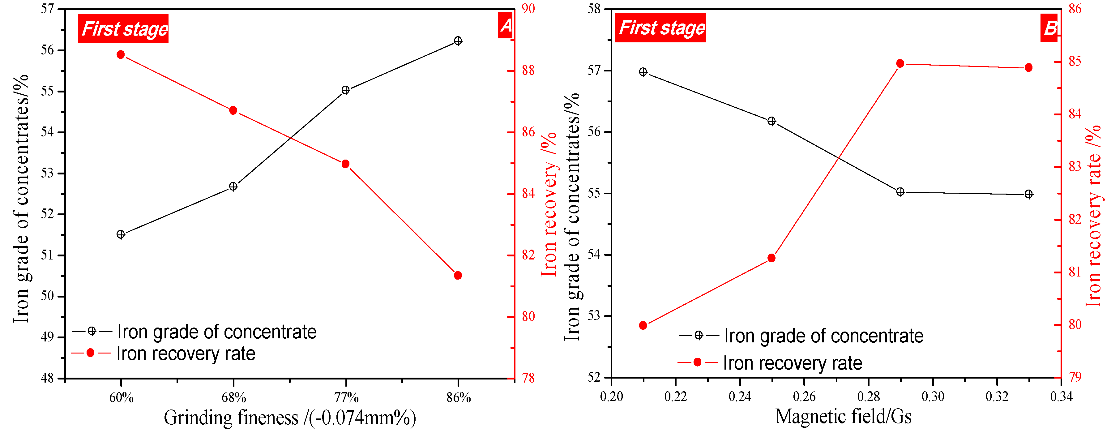
The effects of grinding fineness and intensity of magnetic field on the recovery of iron were investigated and the results are given in Figure 13.
The iron grade was increased gradually from 51.5% to 56.22% with the increase in grinding fineness from 60% below 0.074 mm to 86% below 0.074 mm as shown in Figure 13A, due to the full liberation of magnetite. However, the iron recovery was significantly decreased as grinding fineness was increased in the whole experimental range. Taking full account of iron grade and recovery, the fineness of 77% below −0.074 mm was recommended.
Effect of primary intensity of magnetic field on iron recovery under the condition of primary grinding fineness of −0.074 mm 77% is shown in Figure 13B. As can be seen from that, with an increase of magnetic field intensity from 0.21 T to 0.29 T, the iron recovery was elevated from 79.98% to 84.96%, and iron grade was decreased slightly. Thereafter, it had no significant change when magnetic intensity was further intensified to 0.33 T. Hence, from those experiments, the magnetic field intensity of 0.29 T was taken in the following work.
3.3.2. Second Stage
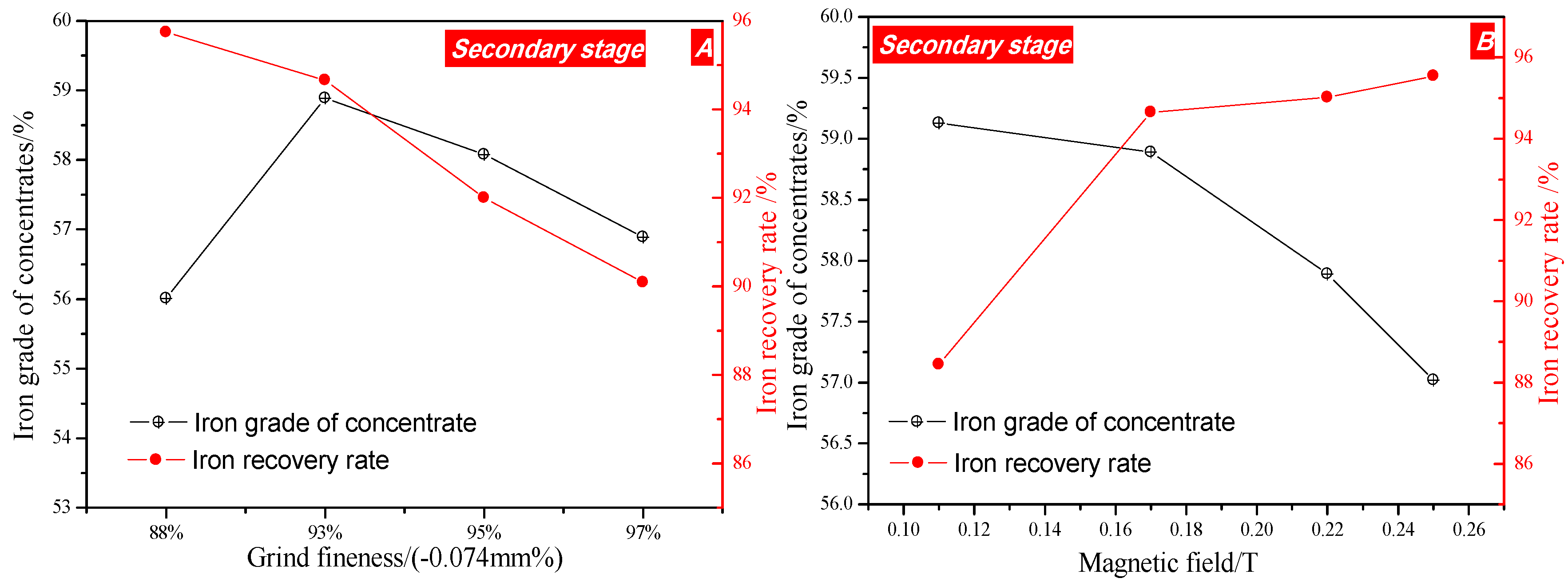
In order to further increase iron grade of concentrate, the primary products were subjected to secondary grinding and magnetic separation, and the result was shown in Figure 14.
As seen from that, when the grinding fineness was increased from 88% below 0.074 mm to 93% below 0.074 mm, the iron grade was improved from 56.01% to 58.89%, and the iron recovery was also decreased gradually. Thereafter, the further increasing the grinding fineness had a detrimental effect on iron recovery and grade. This is accounted by particles aggregation caused by inter-particle magnetic interattraction when the size is too fine, resulting in some gangue minerals being mixed into iron concentrate. Based on this analysis, the size of 93% below −0.074 mm is deemed optimal. The effect of magnetic intensity on the recovery of iron was investigated and the results are given in Figure 14B. It can be seen from that the magnetic intensity has a positive effect on iron recovery, on the contrary, it is not beneficial to iron grade. Comprehensively considered the iron grade and recovery, the suitable magnetic intensity is fixed at 0.17 T.
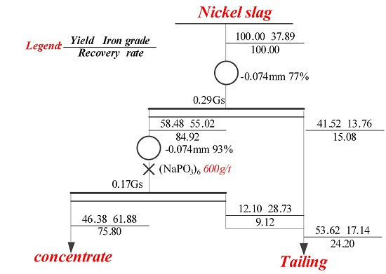
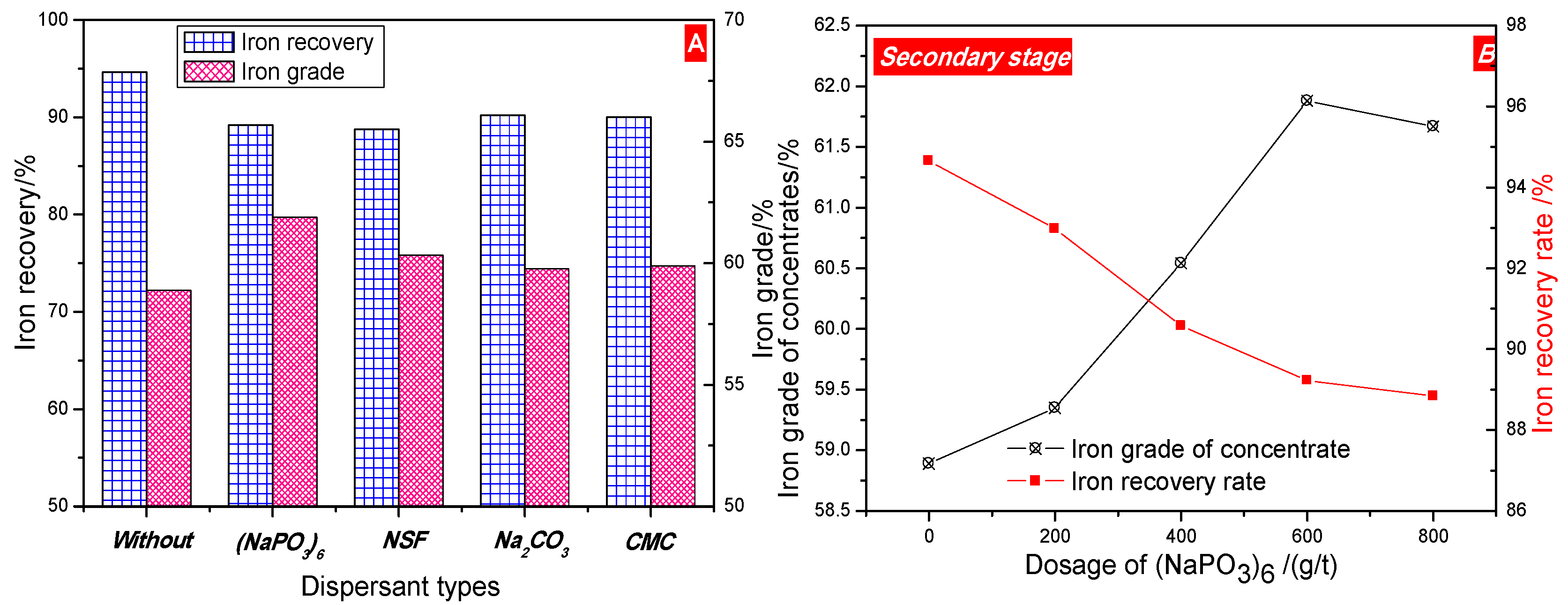
In order to further increase the quality of iron concentrate, different kinds of dispersant were employed to improve the magnetic separation by preventing magnetic aggregation, and results are shown in Figure 15. The results show that sodium hexametaphosphate ((NaPO3)6) has the best dispersing effect for nickel slag. Meanwhile, it is also seen from Figure 15B that the iron grade was increased gradually and reached its peak of 61.89% when the dosage of (NaPO3)6 was raised to 600 g/t, thereafter it remained nearly constant, while the iron recovery was present as the opposite tendency, which reveals the addition of (NaPO3)6 is beneficial to iron grade of concentrate due to the fact that the dispersant can improve the interparticle repulsive force and weaken interparticle magnetic interattraction. Hence, the suitable fineness and intensity of magnetic field in the primary and secondary separation processes should be 77%-0.074 mm and 93%-0.074 mm, as well as 0.29 T and 0.17 T, respectively, and the suitable dosage of (NaPO3)6 is 600 g/t. The magnetic concentrate, assaying total iron grade of 61.88% was obtained at an overall iron recovery of 75.80%.
From the mineralogy of the iron-bearing phases, theoretically it should be possible to improve the iron recovery upon 85% by further finely grinding. Nonetheless, partial iron losses are at all inevitable, which would be related to minor magnetic particles with the very fine size embedded in matrix minerals, and expected to be difficultly liberated.
Based above single factor experiments, the flowsheet of two stage grinding low intensity magnetic separation process is shown in Figure 16. The chemical composition of beneficiation product and tailings is shown in Table 4.
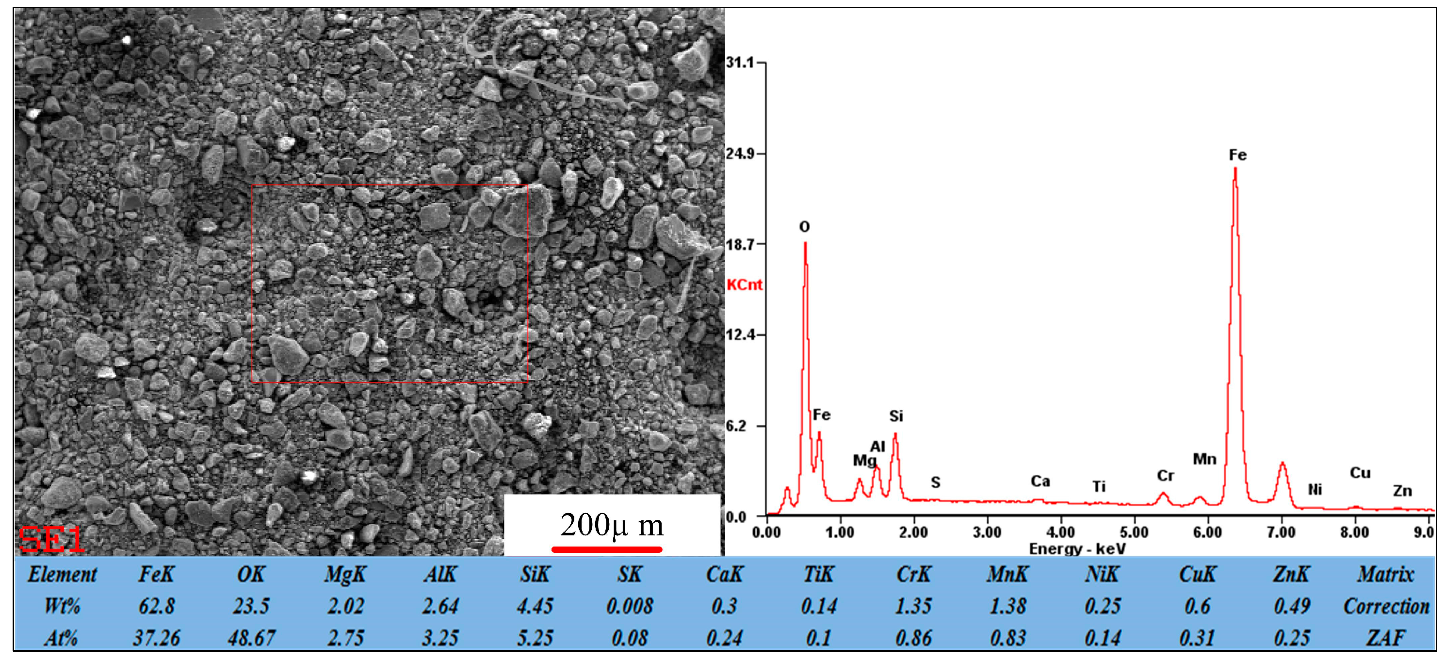
The magnetic concentrate contains 61.88% total iron, 4.21% SiO2 and minor other impurities, such as sulfur and phosphorus. In addition, more notably, the content of Al2O3 and Ni is a little higher within the magnetic concentrates. However, it still can be used as sintering and pelletizing feed blending with other low aluminum and nickel iron ores in ironmaking [36]. The tailings, with the main components of Fe, MgO, Al2O3 and SiO2 mixture are maybe used as raw materials for production of cement, which can avoid land occupancy and minimize environmental risks. The SEM-EDS image of product, as shown in Figure 17, further confirms the minor elements, such as Ni, Cr, exist in magnetite concentrates.
4. Conclusions
The typical nickel slag rejected from reduction-ammonia leaching process (RRAL) in Western Australia was subjected to detailed petrographic and mineralogical investigations to examine the textures of potential minerals. According to mineralogical and chemical characteristics of the slag, a suitable beneficiation process was developed to recover the iron from the slag. Based on the studies carried out, the conclusions can be drawn as follows:
- (1)
- The occurrences of valuable metals, such as iron, chromium, and nickel, in the nickel slag are relatively complicated. Iron mainly exists in the form magnetite and maghemite with a coarse size over 50 μm, which are the main recoverable metal minerals. Chromium exists in the form of picotite, and some Al3+ and Mg2+ cations substitute Cr3+ cations in its lattice. The complicated chemical composition of picotite leads to poor recovery value due to difficult separation by the conventional physical processes. Fe-Ni alloy, as the predominate nickel-bearing phase, disperse in the slag and is closely surrounded by magnetite. Due to their fine and variable distribution, upgrading of nickel minerals by traditional beneficiation processes would be a great challenge.
- (2)
- The process of two stage grinding and two stage low intensity magnetic separation was developed to recover the iron metal. The magnetic concentrate, assaying total iron grade of 61.88% was obtained at 75.80% overall iron recovery under the optimal conditions of the grinding fineness of −0.074 mm 77% and 0.29 T intensity of magnetic field in the first magnetic separation, and the grinding fineness of −0.074 mm 93% and 0.17 T intensity of magnetic field in secondary magnetic separation, which can be used as raw material for subsequently sintering or pelletizing process in ironmaking industry. The (NaPO3)6 addition had a positive effect on the increase in grade of iron concentration.
- (3)
- These process allows for the preliminary utilization of nickel slag. However, further studies are needed to deal with tailings generated from that.
Hence, a feasible technique was presented to economically and environmentally friendly utilize the nickel slag from reduction roasting-ammonia leaching.
Acknowledgments
The authors wish to express their thanks to the National Key Technology R&D Program of China (No. 2013BAB03B04) for the financial support of this research, and also would like to thank Co-Innovation Center for Clean and Efficient Utilization of Strategic Metal Mineral Resources of Hunan Province, which supplied us the facilities and funds to fulfill the experiments.
Author Contributions
Zhengqi Guo and Jian Pan conceived and designed the experiments; Zhengqi Guo and Feng Zhang performed the experiments; Zhengqi Guo and Feng Zhang analyzed the data; Deqing Zhu contributed reagents/materials/analysis tools; Zhengqi Guo wrote the paper.
Conflicts of Interest
The authors declare no conflict of interest.
References
- Dalvi, A.D.; Bacon, W.G.; Osborne, R.C. The Past and the Future of Nickel Laterites. In Proceedings of the PDAC 2004 International Convention, Trade Show and Investors Exchange, Mississauga, ON, Canada, 7–10 March 2004. [Google Scholar]
- Wang, B.; Guo, Q.; Wei, G.; Zhang, P.; Qu, J.; Qi, T. Characterization and atmospheric hydrochloric acid leaching of a limonitic laterite from Indonesia. Hydrometallurgy 2012, 71, 1–6. [Google Scholar] [CrossRef]
- Norgate, T.; Jahanshahi, S. Low grade ores—Smelt, leach or concentrate? Miner. Eng. 2010, 2, 65–69. [Google Scholar] [CrossRef]
- Mudd, G.M. Global trends and environmental issues in nickel mining: Sulfides versus laterites. Ore Geol. Rev. 2010, 38, 9–26. [Google Scholar] [CrossRef]
- McDonald, R.G.; Whittington, B.I. Atmospheric acid leaching of nickel laterites review: Part I. Sulphuric acid technologies. Hydrometallurgy 2008, 91, 35–55. [Google Scholar] [CrossRef]
- Senanayake, G.; Das, G.K. A comparative study of leaching kinetics of limonitic laterite and synthetic iron oxides in sulfuric acid containing sulfur dioxide. Hydrometallurgy 2002, 72, 59–72. [Google Scholar] [CrossRef]
- Kaya, Ş.; Topkaya, Y.A. High pressure acid leaching of a refractory lateritic nickel ore. Miner. Eng. 2011, 24, 1188–1197. [Google Scholar] [CrossRef]
- Liu, K.; Chen, Q.; Hu, H. Comparative leaching of minerals by sulphuric acid in a Chinese ferruginous nickel laterite ore. Hydrometallurgy 2009, 98, 281–286. [Google Scholar] [CrossRef]
- Ma, B.; Wang, C.; Yang, W.; Yin, F.; Chen, Y. Screening and reduction roasting of limonitic laterite and ammonia-carbonate leaching of nickel–cobalt to produce a high-grade iron concentrate. Miner. Eng. 2013, 51, 106–111. [Google Scholar] [CrossRef]
- Caron, M.H. Fundamental and practical factors in ammonia leaching of nickel and cobalt ores. Trans. AIME 1950, 188, 67–90. [Google Scholar]
- Chander, S.; Sharma, V.N. Reduction roasting/ammonia leaching of nickeliferous laterites. Hydrometallurgy 1981, 7, 198–201. [Google Scholar] [CrossRef]
- Chen, S.L.; Guo, X.Y.; Shi, W.T.; Li, D. Extraction of valuable metals from low grade nickeliferous laterite ore by reduction roasting-ammonia leaching method. J Cent. South Univ. Technol. 2010, 17, 765–769. [Google Scholar] [CrossRef]
- Li, Y.; Papangselakis, V.G. High pressure oxidative acid leaching of nickel smelter slag: Characterization of feed and residue. Hydrometallurgy 2009, 97, 185–193. [Google Scholar] [CrossRef]
- Zhang, Y.; Man, R.; Ni, W.; Wan, H. Selective leaching of base metals from copper smelter slag. Hydrometallurgy 2010, 103, 25–29. [Google Scholar]
- Rudnik, E.; Burzysaka, L.; Gumowaska, W. Hydrometallurgical recovery of copper and cobalt from reduction roasted copper converter slag. Miner. Eng. 2009, 22, 85–89. [Google Scholar] [CrossRef]
- Yang, H.; Jing, L.; Dang, C. Iron recovery from copper-slag with lignite-based direct reduction followed by magnetic separation. Chin. J. Nonferr. Met. 2011, 21, 1165–1168. (In Chinese) [Google Scholar]
- Yucel, O.; Sahin, F.; Sirin, B.; Addemir, O.A. Reduction study of copper slag in DC arc furnace. Scand. J. Metall. 1999, 28, 93–97. [Google Scholar]
- Zhou, X.L.; Zhu, D.Q.; Pan, J.; Wu, T.J. Utilization of waste copper slag to produce directly reduced Iron for weathering resistant steel. Int. ISIJ 2015, 55, 1347–1352. [Google Scholar]
- Haselhuhn, H.J.; Kawatra, S.K. The Role of Surface Chemistry in Iron Ore Beneficiation. Miner. Metall. Process. 2017. [Google Scholar]
- Guo, Z.Q.; Zhu, D.Q.; Pan, J.; Wu, T.J.; Zhang, F. Improving beneficiation of copper and Iron from copper slag by modifying the molten copper slag. Metals 2016, 6, 86–96. [Google Scholar] [CrossRef]
- Zhu, D.Q.; Guo, Z.Q.; Pan, J.; Zhang, F. Mechanism of mineral phase reconstruction for improving the beneficiation of copper and iron from copper slag. JOM 2016, 68, 2341–2348. [Google Scholar]
- Batchelor, A.R.; Jones, D.A.; Plint, S.; Kingman, S.W. Increasing the grind size for effective liberation and flotation of a porphyry copper ore by microwave treatment. Miner. Eng. 2016, 94, 61–75. [Google Scholar] [CrossRef]
- Meng, X.L. Phase analysis and research of the iron ore. Chin. Chem. Trade 2013, 8, 231–258. [Google Scholar]
- Zhao, S.B. Chemical Phase Analysis of iron ore. Mater. High Speed Anal. 1996, 23, 60–65. (In Chinese) [Google Scholar]
- Zhang, H.B. Chemical Phase Analysis of Ores and Industrial Products; Metallurgical Industry Press: Beijing, China, 1992. (In Chinese) [Google Scholar]
- Powell, M.; Bye, A. Beyond mine-to-mill: Circuit design for energy efficient resource utilization. In Proceedings of the Tenth Mill Operators Conference, Adelaide, Australia, 12–14 October 2009; AusIMM: Carlton South, Australia, 2009; pp. 357–364. [Google Scholar]
- Mohanan, S.; Bhoja, S.K.; Kumar, C.R.; Kumar, A.; Venugopalan, T. Estimation of ore mineralogy from analytical analysis of iron ore. Miner. Metall. Process. 2015, 32, 97–101. [Google Scholar]
- Chen, W. Experimental research of recovering easy-to-slime limonite by flocculation-high intensity magnetic separation technology. Met. Mine 2003, 6, 32–34. [Google Scholar]
- Jun, B.S.; Wen, L.D.; Wen, S.M. Test research on mineral dressing-metallurgy combination processing of a refractory limonite ore. Mine Metall. 2009, 18, 16–20. [Google Scholar]
- Graca, L.M.; Lagoeiro, L.E.; Lima, R.M.F.; Barbosa, P.F.; Machado, M.M. Effect of the morphological types in grinding of iron-ore products. Miner. Process. Extr. Metall. Rev. 2015, 36, 324–331. [Google Scholar] [CrossRef]
- Miao, L.; He, Y.S.; Kang, J.T.; Kumar, A.; Venugopalan, T. Why was iron lost without significant isotope fractionation during the lateritic process in tropical environments? Geoderma 2017, 290, 1–9. [Google Scholar]
- Li, B.; Wang, H.; Wei, Y. The reduction of nickel from low-grade nickel laterite ore using a solid-state deoxidization method. Miner. Eng. 2011, 24, 1556–1562. [Google Scholar] [CrossRef]
- Sun, Y.S.; Han, Y.X.; Gao, P.; Yu, J.W. Size distribution behavior of metallic iron particles in coal-based reduction products of an oolitic iron ore. Miner. Process. Extr. Metall. Rev. 2015, 36, 249–257. [Google Scholar] [CrossRef]
- Haselhuhn, H.J.; Kawatra, S.K. Flocculation and Dispersion Studies of Iron Ore using Laser Scattering Particle Size Analysis. Miner. Metall. Process. 2015, 32, 191–196. [Google Scholar]
- Liu, S.; Wang, W.; Zhang, M.; Wen, S. Beneficiation of a low grade hematite-magnetite ore in China. Miner Metall. Process. 2014, 31, 136–142. [Google Scholar]
- Fu, J.Y.; Jiang, T.; Zhu, D.Q. Principle of Sintering and Pelletizing; Central South University of Technology Press: Changsha, China, 1996. [Google Scholar]
Figure 1.
The size distribution of nickel slag and the fraction of Fe, SiO2 and Al2O3 in the different sizes.
Figure 1.
The size distribution of nickel slag and the fraction of Fe, SiO2 and Al2O3 in the different sizes.
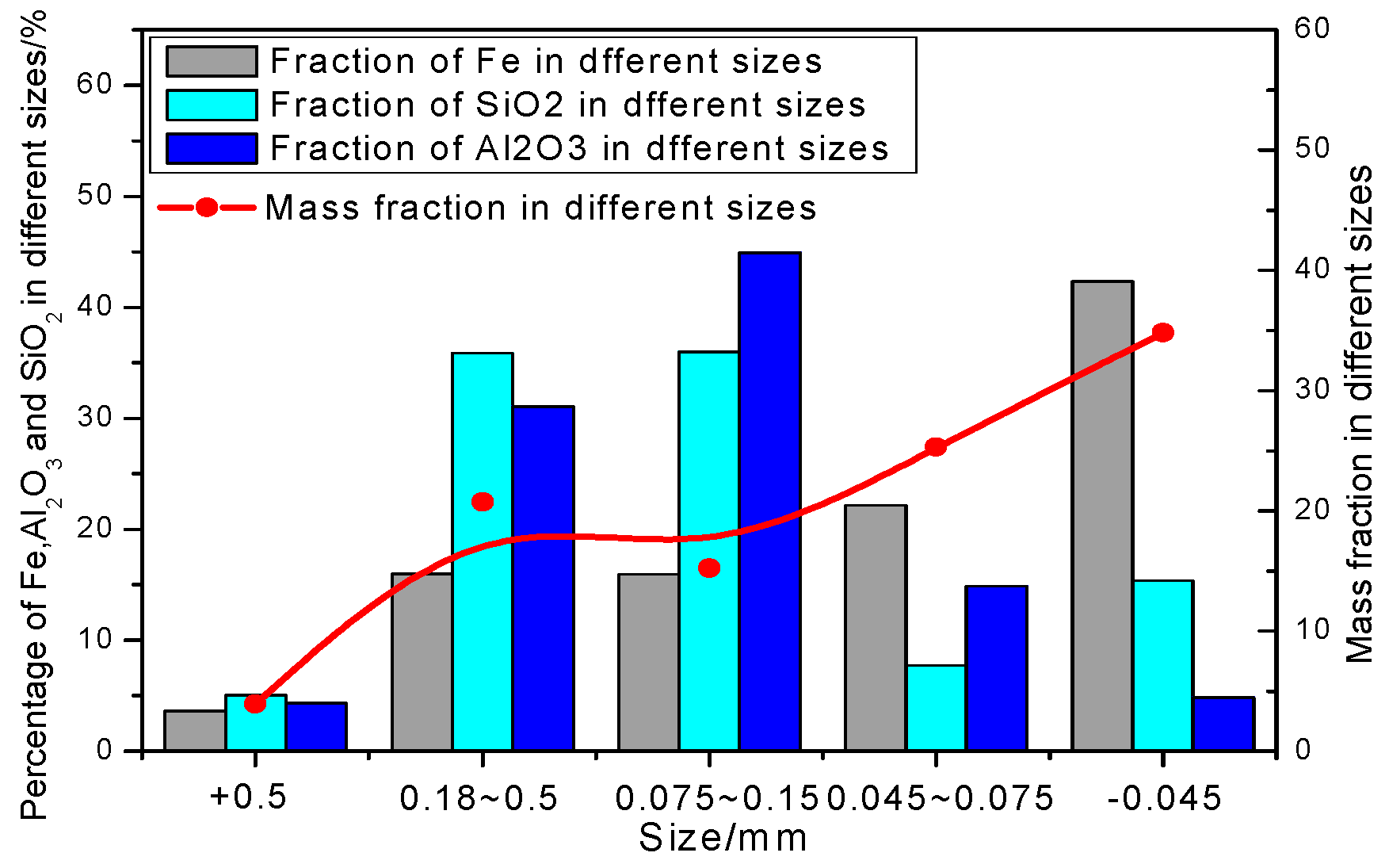
Figure 2.
The flowsheet for determining iron chemical phase.
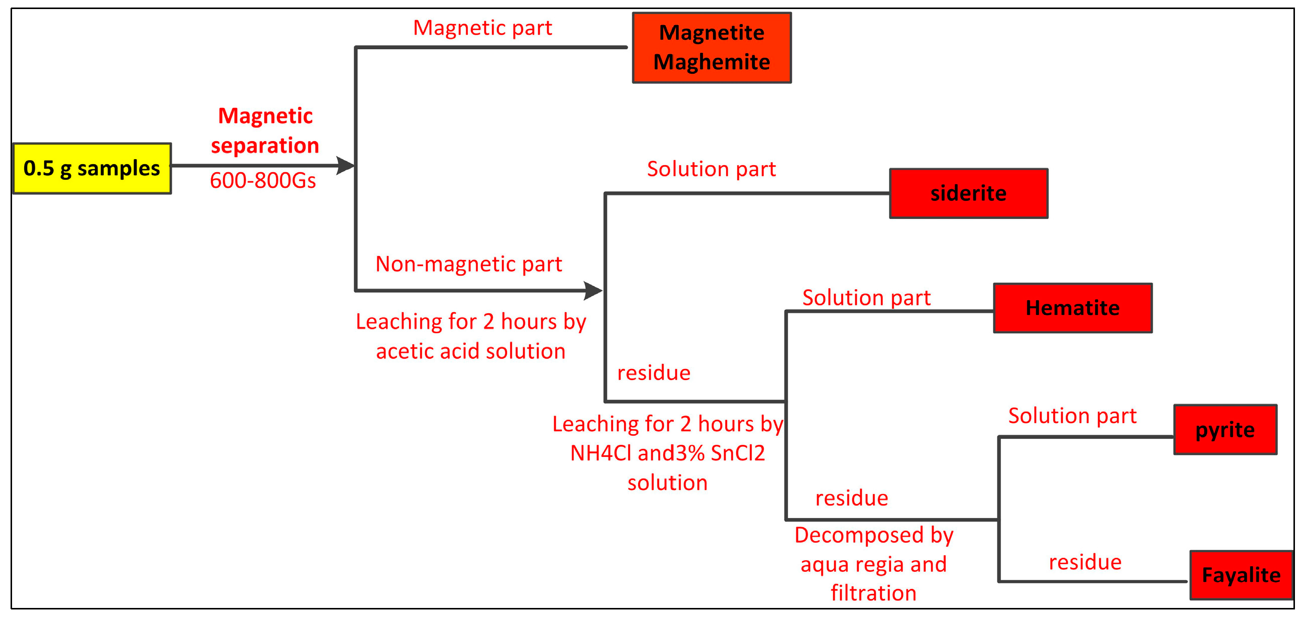
Figure 3.
XRD patterns of the nickel slag.
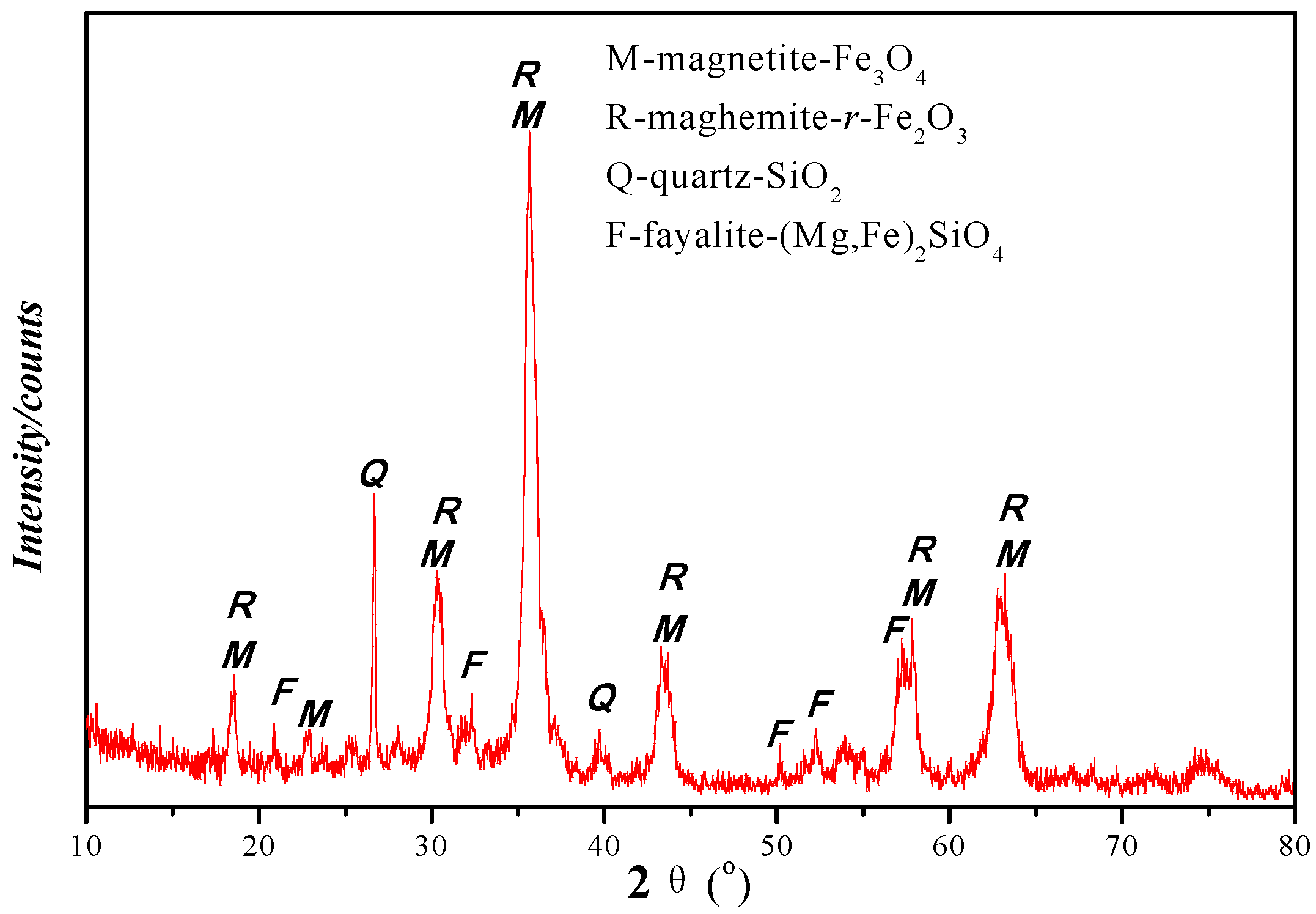
Figure 4.
Liberation degree of magnetite within the nickel slag determined by microscopic image measurement method: A—Magnetite free liberation degree; B—The percentage of Intergrowth particles having greater than 75% magnetite; C—The percentage of Intergrowth particles having 50–75% magnetite; D—The percentage of Intergrowth particles having 25–50% magnetite; E—The percentage of Intergrowth particles with less than 25% magnetite.

Figure 5.
Photomicrographs of typical iron-bearing minerals textures in the slag: M—magnetite; H—maghemite; F—argillite.
Figure 5.
Photomicrographs of typical iron-bearing minerals textures in the slag: M—magnetite; H—maghemite; F—argillite.
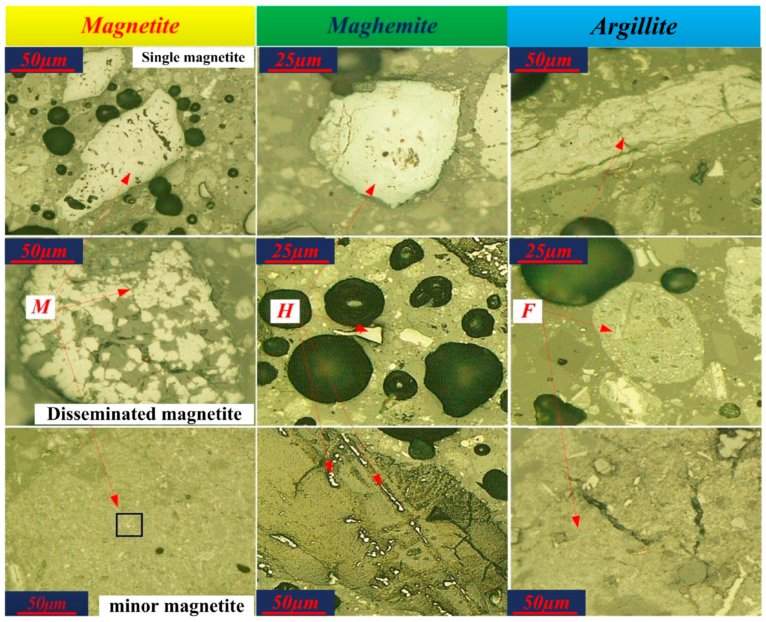
Figure 6.
SEM back-scattered electron images of section minor magnetite as shown in Figure 4: M—magnetite, B—gangue minerals, (A) backscattering electronic image of fine magnetite particle; (B) surface scanning images of Fe; (C) surface scanning images of Si; (D) surface scanning images of Al.
Figure 6.
SEM back-scattered electron images of section minor magnetite as shown in Figure 4: M—magnetite, B—gangue minerals, (A) backscattering electronic image of fine magnetite particle; (B) surface scanning images of Fe; (C) surface scanning images of Si; (D) surface scanning images of Al.
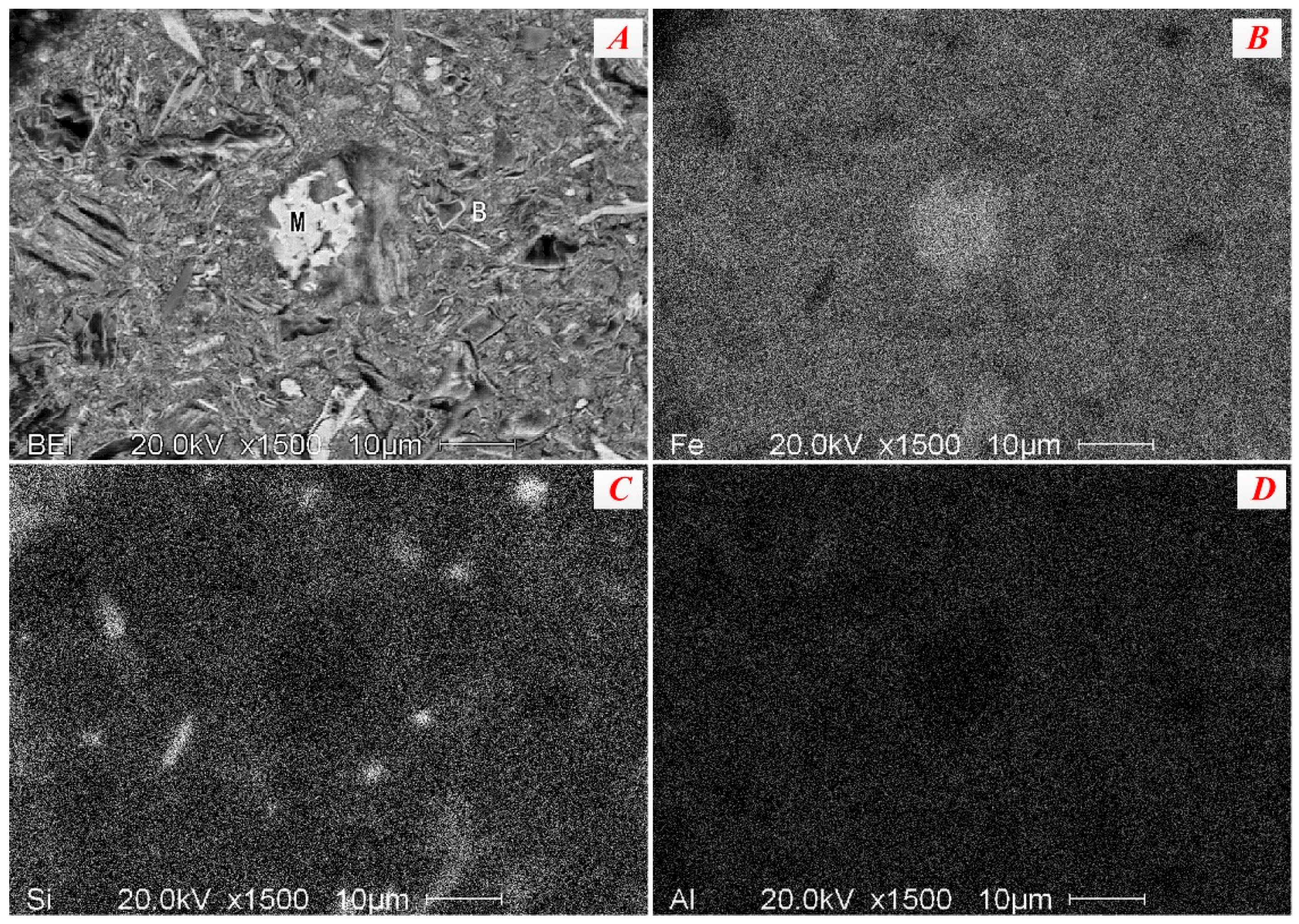
Figure 7.
Micrographs of picotite in the nickel slag.
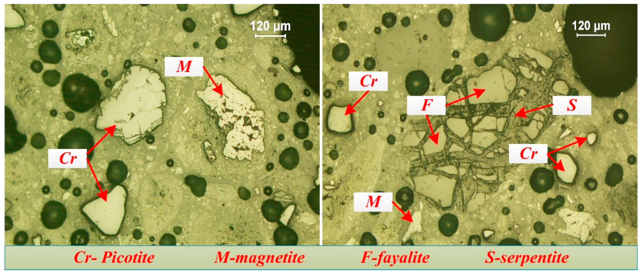
Figure 8.
ESEM results of slag sample ((A) backscattering electronic image; (B–F) surface scanning images of Cr, Fe, Al, Mg and Mn, respectively. (Cr-picotite, B-gangue)).
Figure 8.
ESEM results of slag sample ((A) backscattering electronic image; (B–F) surface scanning images of Cr, Fe, Al, Mg and Mn, respectively. (Cr-picotite, B-gangue)).
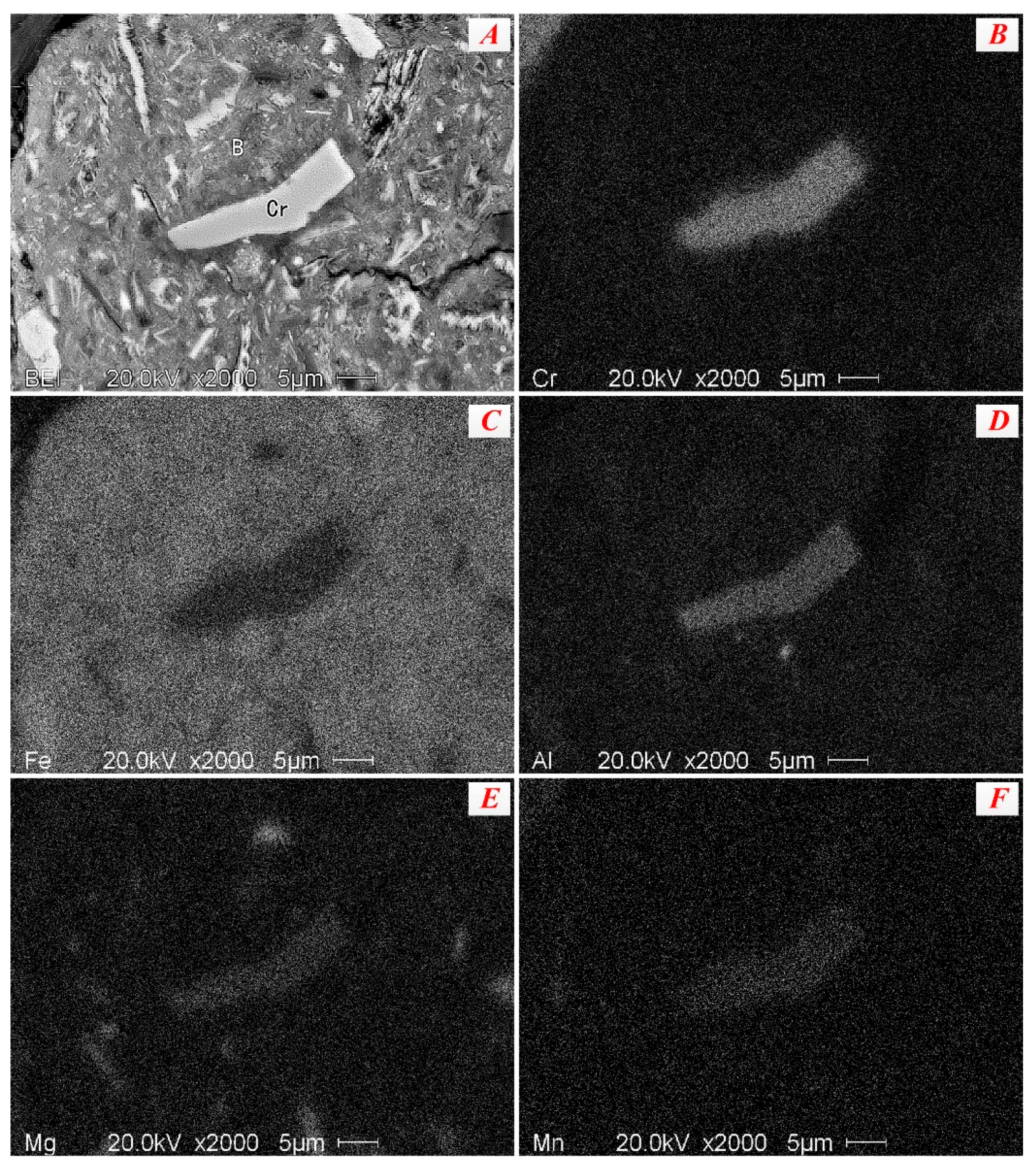
Figure 9.
SEM-EDS spectrums of the representative point in the picotite particles.
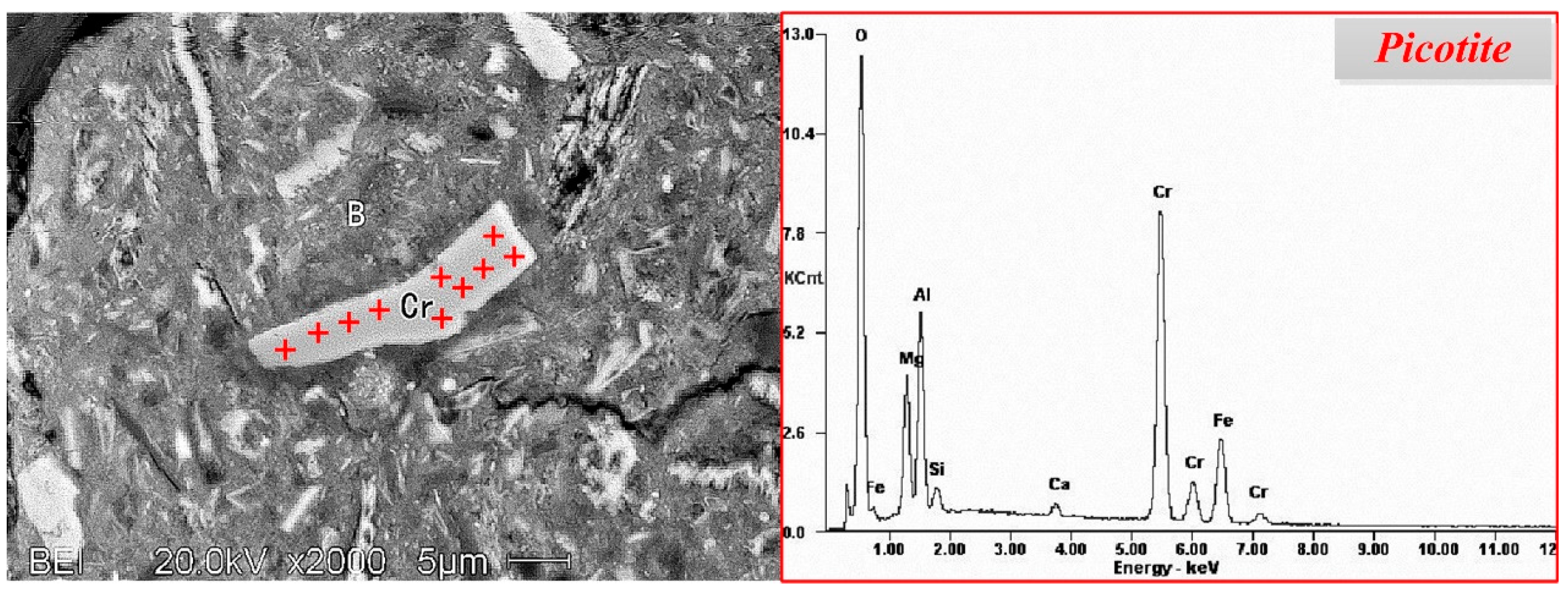
Figure 10.
Thermodynamic analysis of reduction of metal oxides ((a) The standard Gibbs free energy of reactions (4)–(10) on the different temperatures; (b) Restore balance of cobalt oxide, nickel oxide and iron oxides).
Figure 10.
Thermodynamic analysis of reduction of metal oxides ((a) The standard Gibbs free energy of reactions (4)–(10) on the different temperatures; (b) Restore balance of cobalt oxide, nickel oxide and iron oxides).
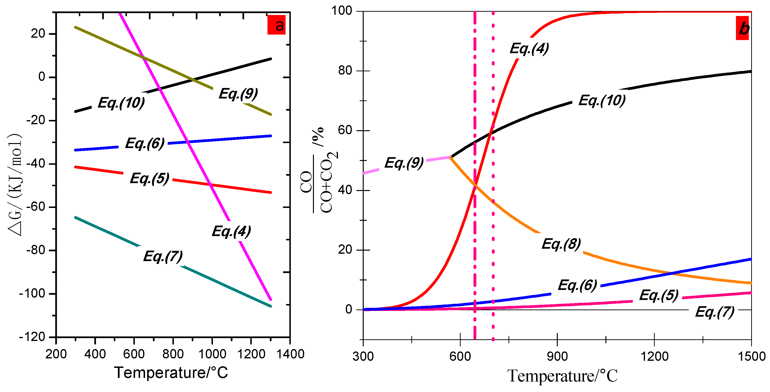
Figure 11.
Phase diagram of Fe-Ni.
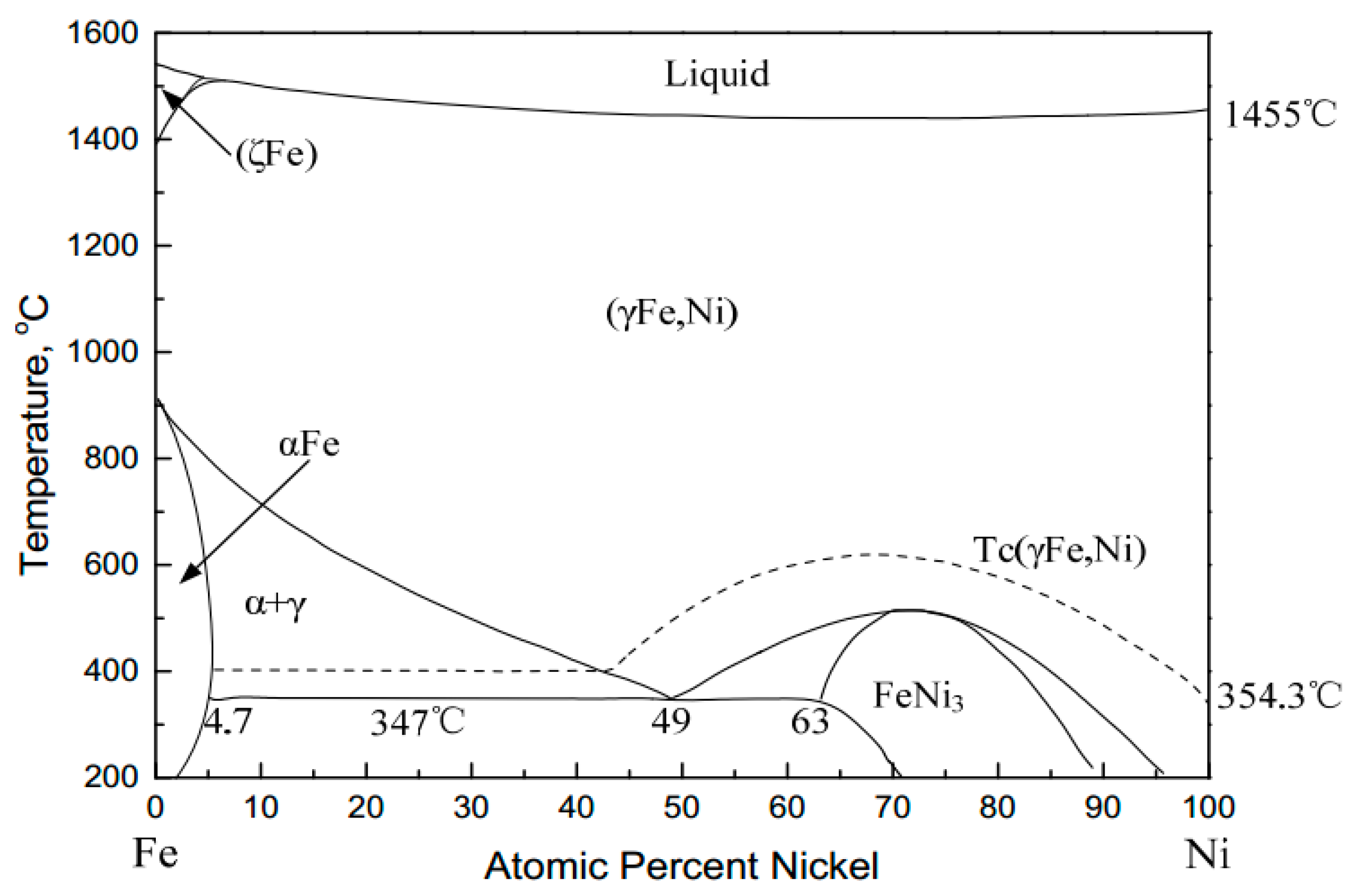
Figure 12.
SEM image and EDS elemental maps of Ni-bearing minerals in nickel slag (M—magnetite; (a)—Backscattered photomicrograph of the alloys displaying the fine grain size; (b)—surface scanning images of Ni; (c)—surface scanning images of Fe; (d)—EDS pattern of Fe-Ni alloy).
Figure 12.
SEM image and EDS elemental maps of Ni-bearing minerals in nickel slag (M—magnetite; (a)—Backscattered photomicrograph of the alloys displaying the fine grain size; (b)—surface scanning images of Ni; (c)—surface scanning images of Fe; (d)—EDS pattern of Fe-Ni alloy).
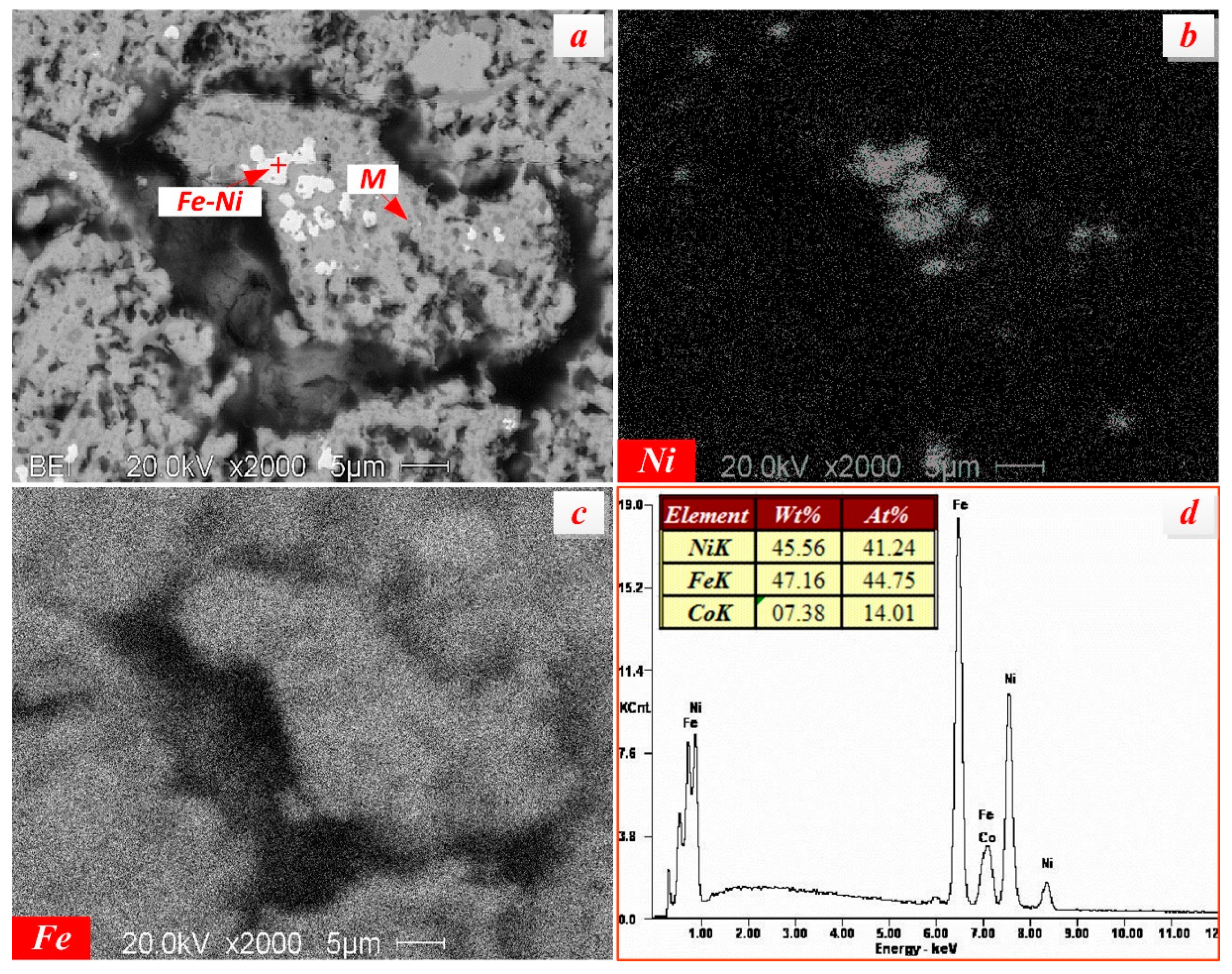
Figure 13.
The results of first stage grinding-low intensity magnetic separation process ((A)—Effect of primary grinding fineness on iron recovery at 0.29 T magnetic field; (B)—Effect of primary intensity of magnetic field on iron recovery under the condition of primary grinding fineness of −0.074 mm 77%).

Figure 14.
The results of secondary stage grinding-low intensity magnetic separation process: (A)—Effect of secondary grinding fineness on iron recovery at 0.17 T magnetic field; (B)—Effect of primary intensity of magnetic field on iron recovery under the condition of secondary grinding fineness of −0.074 mm 93%, no dispersing agent.

Figure 15.
Effects of dispersant on recovery of iron: (A) Effect of dispersant types on iron recovery (600 g/t); (B) Effect of (NaPO3)6 addition on iron recovery.
Figure 15.
Effects of dispersant on recovery of iron: (A) Effect of dispersant types on iron recovery (600 g/t); (B) Effect of (NaPO3)6 addition on iron recovery.

Figure 16.
Flowsheet of two stage grinding low intensity magnetic separation process.
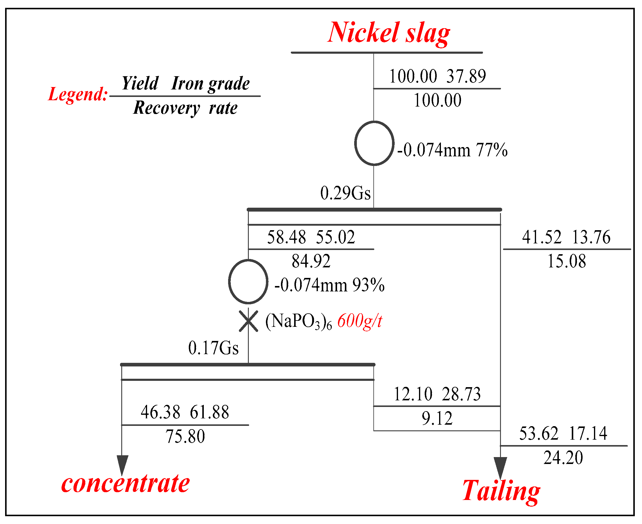
Figure 17.
SEM-EDS image of magnetic concentrates obtained from the nickel slag under the optimal conditions.
Figure 17.
SEM-EDS image of magnetic concentrates obtained from the nickel slag under the optimal conditions.


Table 1.
Chemical compositions of nickel slag (wt %).
| Elements | TFe | Ni | Cr2O3 | SiO2 | CaO | MgO | Al2O3 | Pb | Zn | S | P | LOI |
|---|---|---|---|---|---|---|---|---|---|---|---|---|
| Content | 37.86 | 0.32 | 5.57 | 19.76 | 0.17 | 9.31 | 5.31 | 0.03 | 0.05 | 0.43 | 0.02 | 0.18 |
Table 2.
The distribution of iron in associated minerals (wt %).
| Mineral | Magnetite | Maghemite | Hematite | Fayalite | Others | Fetotal |
|---|---|---|---|---|---|---|
| Content | 28.68 | 4.73 | 0.97 | 2.08 | 1.40 | 37.86 |
| Fraction | 75.75 | 12.49 | 2.56 | 5.49 | 3.69 | 100.00 |
Table 3.
Representative chemical compositions of picotite within the slag (wt %).
| Positions | Chemical Compositions | |||||
|---|---|---|---|---|---|---|
| Cr2O3 | FeO | CaO | MgO | SiO2 | Al2O3 | |
| 1 | 50.43 | 17.85 | 0.80 | 10.34 | 1.56 | 19.02 |
| 2 | 45.69 | 15.97 | 0.90 | 14.76 | 1.70 | 20.98 |
| 3 | 48.84 | 17.50 | 0.75 | 10.08 | 1.67 | 21.16 |
| 4 | 44.98 | 15.82 | 1.21 | 14.24 | 2.33 | 21.41 |
| 5 | 52.62 | 20.96 | 0.72 | 9.26 | 1.67 | 14.77 |
| 6 | 48.29 | 20.48 | 0.82 | 10.78 | 1.29 | 18.34 |
| 7 | 38.83 | 15.19 | 1.04 | 14.70 | 1.73 | 28.51 |
| 8 | 51.70 | 17.56 | 1.15 | 11.03 | 0.80 | 18.06 |
| 9 | 45.78 | 16.48 | 1.40 | 13.41 | 1.04 | 21.89 |
| 10 | 46.62 | 17.23 | 1.20 | 13.51 | 1.71 | 19.74 |
| Average | 47.35 | 17.50 | 1.00 | 12.21 | 1.55 | 20.39 |
Table 4.
Chemical compositions of magnetic concentrate from the nickel slag (wt %).
| Elements | TFe | SiO2 | CaO | MgO | Al2O3 | S | P | Ni | Mn | Cr |
|---|---|---|---|---|---|---|---|---|---|---|
| Concentrates | 61.88 | 4.21 | 0.15 | 1.34 | 2.33 | 0.06 | 0.004 | 0.21 | 0.82 | 2.08 |
| Tailings | 17.88 | 34.21 | 0.19 | 17.15 | 7.09 | 0.68 | 0.04 | 0.40 | 1.12 | 5.01 |
© 2017 by the authors. Licensee MDPI, Basel, Switzerland. This article is an open access article distributed under the terms and conditions of the Creative Commons Attribution (CC BY) license (http://creativecommons.org/licenses/by/4.0/).
Share and Cite
MDPI and ACS Style
Guo, Z.; Zhu, D.; Pan, J.; Zhang, F. Mineralogical Characteristics and Preliminary Beneficiation of Nickel Slag from Reduction Roasting-Ammonia Leaching. Minerals 2017, 7, 98. https://doi.org/10.3390/min7060098
AMA Style
Guo Z, Zhu D, Pan J, Zhang F. Mineralogical Characteristics and Preliminary Beneficiation of Nickel Slag from Reduction Roasting-Ammonia Leaching. Minerals. 2017; 7(6):98. https://doi.org/10.3390/min7060098
Chicago/Turabian StyleGuo, Zhengqi, Deqing Zhu, Jian Pan, and Feng Zhang. 2017. "Mineralogical Characteristics and Preliminary Beneficiation of Nickel Slag from Reduction Roasting-Ammonia Leaching" Minerals 7, no. 6: 98. https://doi.org/10.3390/min7060098
Note that from the first issue of 2016, this journal uses article numbers instead of page numbers. See further details here.