Article

Visual Exploration of the Spatiotemporal Evolution Law of Overburden Failure and Mining-Induced Fractures: A Case Study of the Wangjialing Coal Mine in China

1
School of Mines, China University of Mining and Technology, Xuzhou 221116, China
2
State Key Laboratory of Coal Resources and Safe Mining, China University of Mining and Technology, Xuzhou 221116, China
3
IoT Perception Mine Research Center, National and Local Joint Engineering Laboratory of Internet Application Technology on Mine, China University of Mining and Technology, Xuzhou 221008, China
*
Author to whom correspondence should be addressed.
Minerals 2017, 7(3), 35; https://doi.org/10.3390/min7030035
Submission received: 9 November 2016 / Accepted: 22 February 2017 / Published: 2 March 2017

Abstract

:
The borehole television approach is an effective way of detecting mining-induced fractures in overburden strata as it can visualize fractures to facilitate a quantitative analysis of size, quantity, length, and other features. In this article, the borehole television approach is applied on panel 20105 of the Wangjialing Coal Mine in China to investigate the overburden movement and spatiotemporal evolution law of mining-induced fractures from the coal seam to ground surface. The results revealed that the overburden strata experienced the phases of roof caving, generation of fracture, bed separation, dislocations, fracture propagation, surface subsidence, and closing of fractures. The process can be divided into the initiation stage, the active stage, and the degradation stage along the mining direction. For exploited working faces, the caved zone height is 2.9–4.11 times the mining height, and the height of the fractured zone is 19.35–22.19 times the mining height. The height range of the three parts in the fractured zone is 24–26, 40–45, and 30–35 m. Significant fractures were observed in the bending zone. Step subsidence and cracks, which indicate severe damages, were observed on the ground surface above the goaf.

1. Introduction

Large-scale longwall mining of coal seams may cause movement of overburden strata and mining-induced fractures. This could lead to a series of mine safety and environmental issues, including cracks on the surface, water loss, vegetation deterioration, land desertification, and water inrush [1,2,3,4]. Therefore, an accurate and effective understanding of the spatiotemporal evolution law of mining-induced fractures in overlying strata is critical.
It is well known that there are three distinct zones (caved zone, fracture zone and continuous deformation zone) of movement in the overburden rock mass above longwall coal mines. Over the past decades, a variety of numerical and physical simulation methods and detection methods have been used to study the development characteristics of mining-induced fractures in overlying strata [5,6,7,8,9]. Currently, the most widely used methods to detect fracture propagation include the double end seal with water injection method, the transient electromagnetic method, the micro-seismic monitoring method and ultrasonic imaging method. Because the mining-induced fracture and strata movement is buried deep underground, these traditional monitoring methods, which use the parameter inversion to speculate the fracture, cannot show visualizing characteristics of shape and size of mining-induced fractures [10,11].
Borehole television is a device based on optical techniques to provide direct images of boreholes in the form of a film or video. This method has many advantages in determining the breakage height and time of the overburden strata and visualizing the morphology and size of mining-induced fractures. Hence, the borehole television approach has been widely applied to identify lithology, determine coal seam thickness, and to observe the separation of roadway roofs and deformation of surrounding rocks [12,13,14,15,16]. Tan et al. used a borehole camera technology to explore the zonal disintegration developing process in roof strata influenced by multiple mining activities [17,18,19]. Xiong et al. used the three-borehole method (multi-point displacement measuring, the double end seal with water injection method and borehole television photographing) for the overburden failure law in an upper protected coal seam while the lower protective seam is mined [20]. Zhang et al. studied the distribution and propagation of various mining-induced fractures and found that transverse and longitudinal fractures intersect with each other, while a high degree longitudinal fractures dominate and become crushing fractures as they approach the roof [21]. Gao et al. used results obtained by the borehole to construct the equation for the location and quantity of fractures in overburden strata and demonstrated that most fractures were concentrated behind the coal wall [22]. Currently, the borehole television approach has been applied to investigate the distribution and propagation of mining-induced fractures, but not the dynamic evolution of fractures during mining, which is a key characteristic of overburden strata.
In this article, the borehole television approach is applied on the working face 20105 of the Wangjialing Mine in China to visually detect (1) mining-induced fractures in overburden strata; (2) movement failure of coal seam-overburden stratum-ground surfaces; (3) temporal and spatial evolution of mining-induced fractures, exfoliation, and caving of overburden strata.

2. Mine Conditions and Mining Techniques

Located in the western part of Shanxi Province, Hedong coalfield is the largest coking coal reservoir in China. This coalfield has a weathered mountain morphology with limited vegetation and a thick loess layer (10–125 m). The migrating direction length and dipping direction length of panel 20105 are 1231 and 249.4 m, respectively. The #2 coal seam has a thickness of 5.91–6.45 m (average 6.18 m) and a dip angle of 2°–4°. The ground elevation and coal seam floor elevation are 750–885.5 m and 554.6–582.9 m, respectively. The longwall top coal caving method (caving 3.0 m, mining 3.2 m) was used. Figure 1 shows the arrangement of panel 20105.

3. Field Monitoring

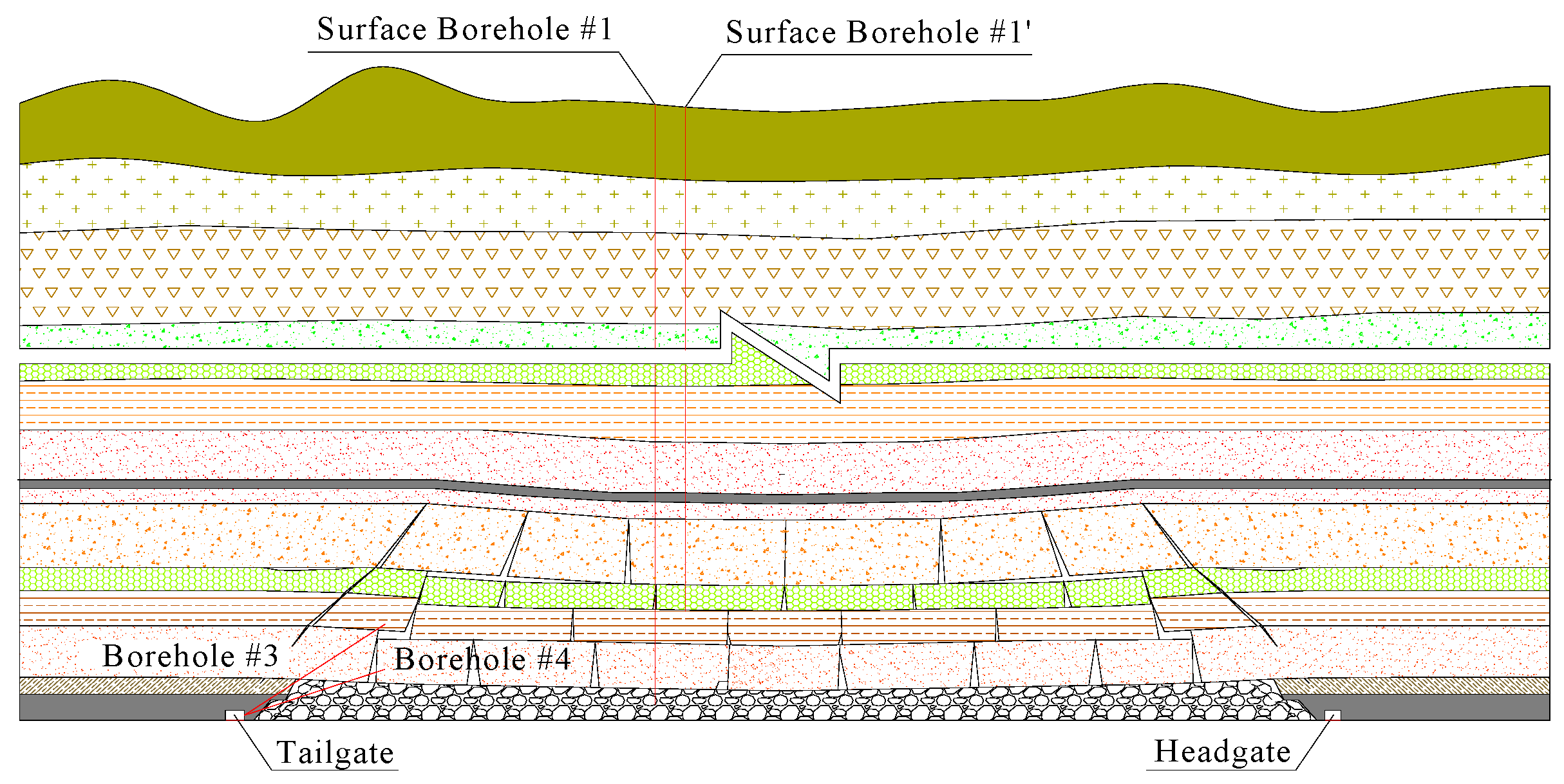
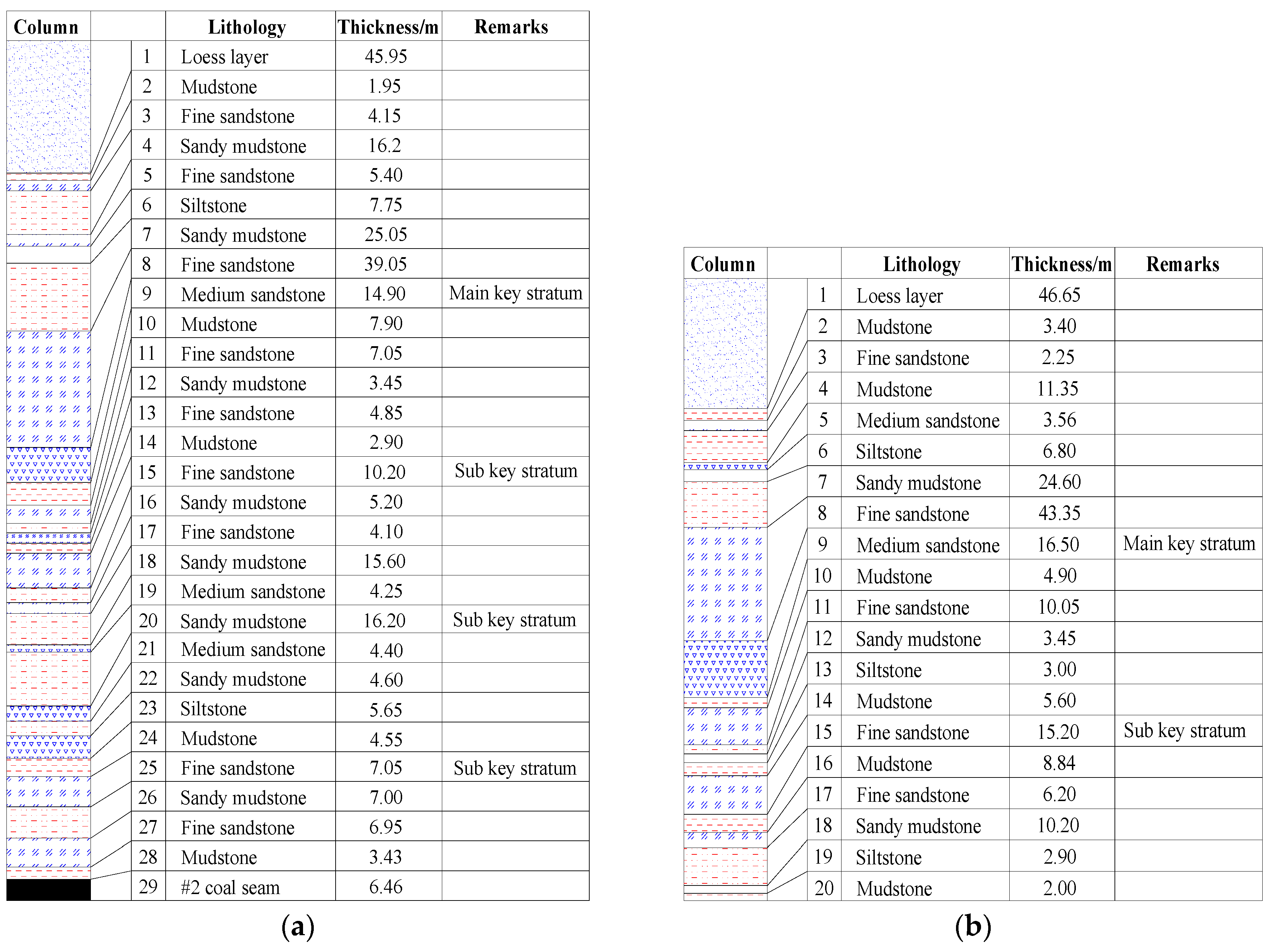
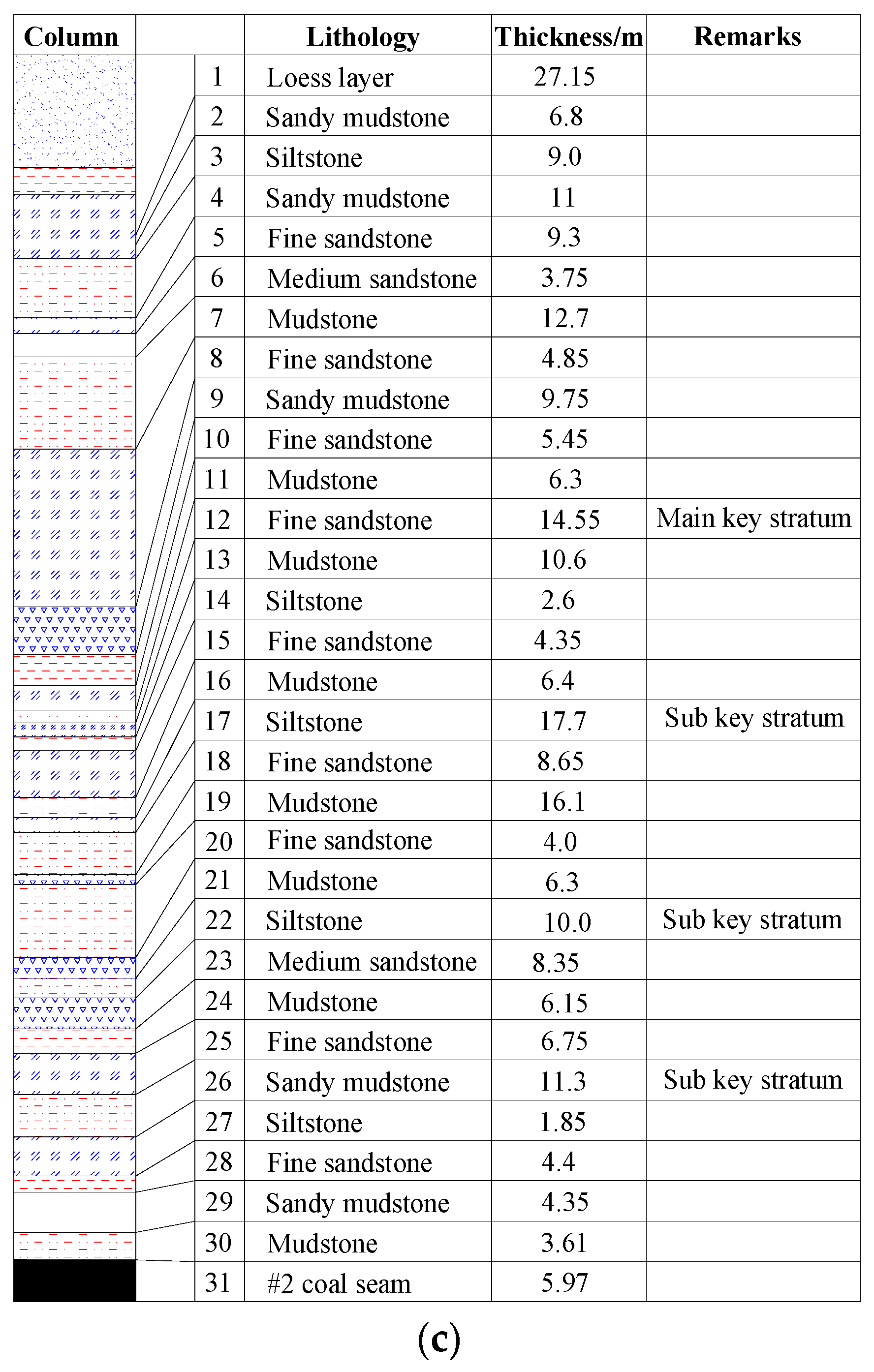
3.1. Arrangement of Boreholes

In order to explore the propagation of overburden cracks, five boreholes were specially drilled, including three surface boreholes and two underground boreholes. Surface boreholes, each 110 mm in diameter, were vertically drilled from the surface to the No. 2 coal seam (Figure 2). They were positioned in the middle of the working face. Boreholes #1 and #1’ were 665 m away from the main haulage roadway. Borehole #2 was 230 m away from the main haulage roadway. The stratigraphic columns of the holes are shown in Figure 3. These boreholes were used to monitor movement and damages from the overburden strata to the surface during mining. Underground boreholes, no less than 70 mm in diameter, are drilled in the roadway of the working face. The elevation angles of borehole #3 and #4, within one vertical surface, are 22° and 30° respectively (Figure 2 and Figure 4). These boreholes were used to monitor movement of the overburden strata and fracture propagation. Boreholes #1, #2, #3 and #4 are drilled before the mining process and the TYGD10 stratum borehole monitor (Figure 5) is used to record the underground situation during working face mining.

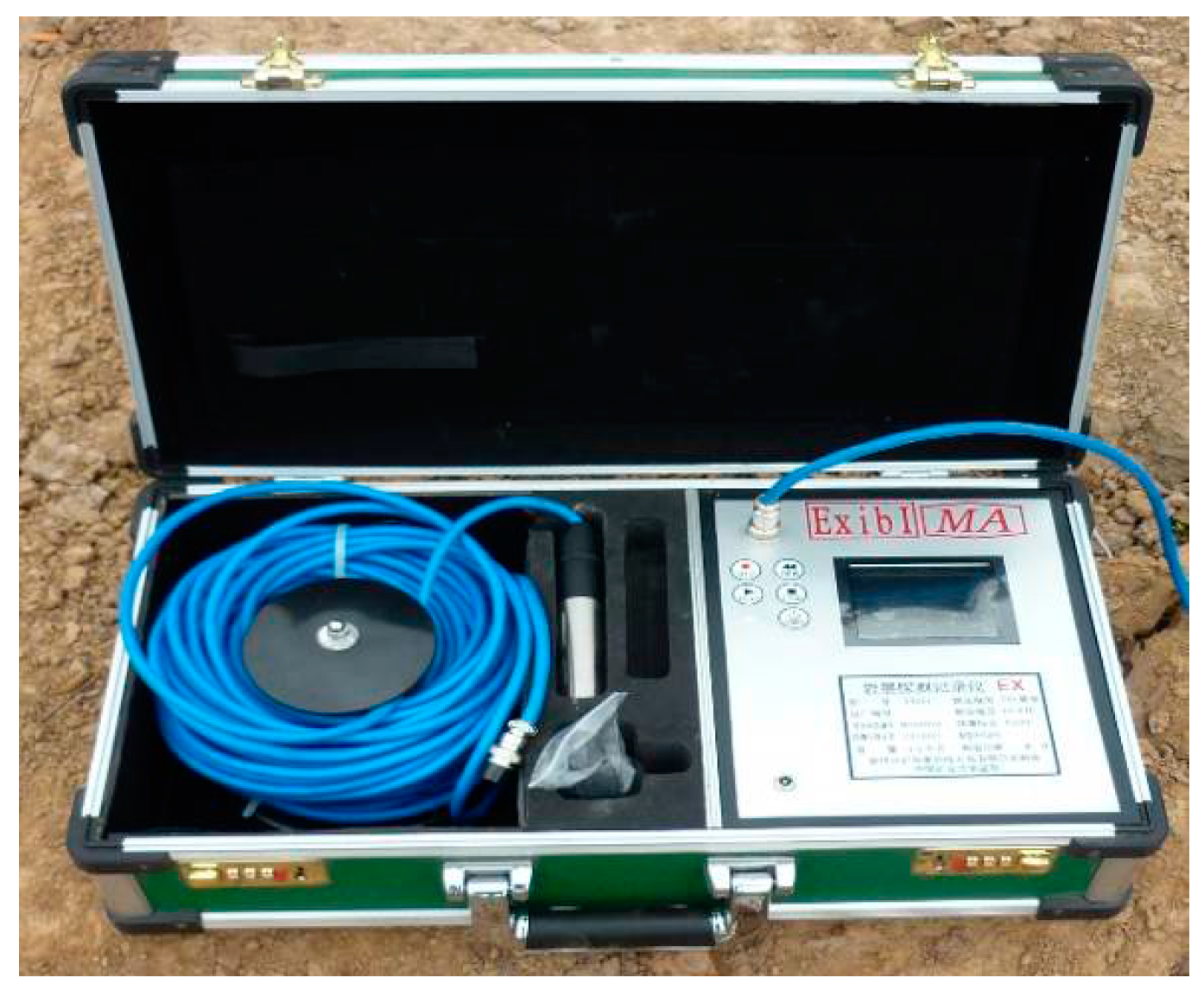
3.2. Monitoring via Surface Borehole

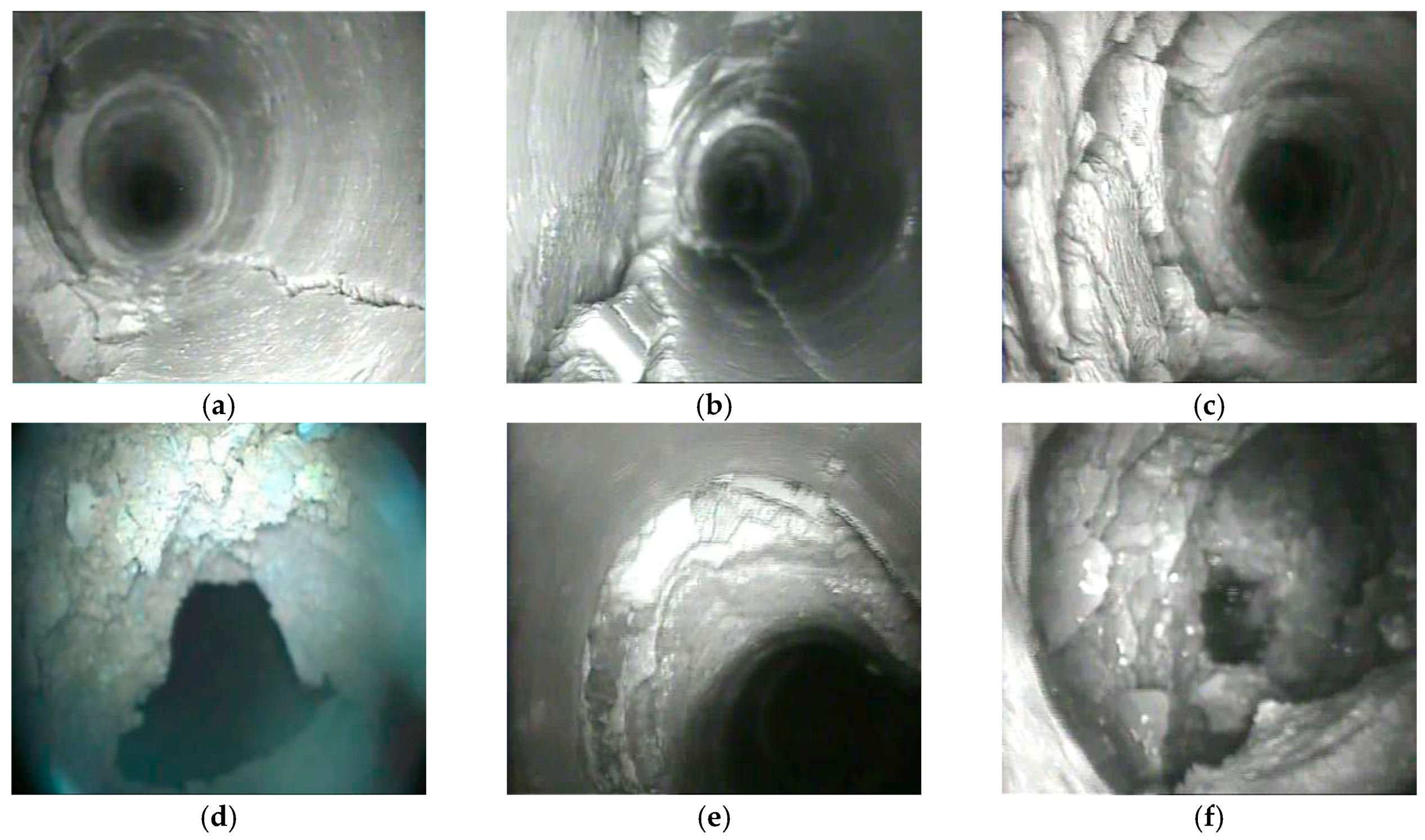
3.2.1. Strata Movement and Fracture Propagation in Borehole #1 and #1’

Borehole #1 was drilled from 6 May 2013 to 2 June 2013. The drill core was relatively intact (with a few exceptions), and the core recovery rate exceeds 70%. The observation started when the working face was 143 m ahead of the borehole and ended when the working face was 160 m past the borehole; the face moved forward at a rate of 5 m/day.
When the working face was 96.7 m away from borehole #1, cracks (Figure 6a) first appeared in the area around borehole #1 and its size increased as the working face moved forward. As a result, the borehole opening was divided in half (Figure 6b). Then, deformation and cracks were observed in the epipedon (Figure 6d), and vertical fractures in the mudstone beneath the epipedon appeared.
When the working face was 29.2 m away from the borehole, the borehole opening deformed and the epipedon deformation was exacerbated with exfoliation of the borehole wall (Figure 6e–f). Meanwhile, vertical fractures appeared on 63–79 m deep bedrocks. Then, the borehole opening deformation (Figure 6c) was exacerbated. The quantity and size of vertical fractures on the bedrocks continuously increased, while horizontal fractures were observed. However, no obvious fractures appeared on bedrocks under 80 m deep.
When the working face was 11.9 m away from the borehole, the borehole opening was divided into two parts, with a height difference of 12 cm. Fractures (Figure 7a) were observed in mudstone at depths of 282.3–285.7 m. Shortly after the working face passed the borehole, the loess layer subsided severely above goaf, and the height difference increased to 30 cm. The influence of mining to the fracture propagation in the borehole was significantly increased and the propagation rate of fractures was obviously faster than before.
When the working face was 13.2 m past the borehole, caving of the immediate roof and strata at a depth of 282 m (Figure 7d) was observed. When the working face was 26.5 m past the borehole, failure of the main roof (the first sub key stratum) was observed and the caving height reached 21.6 m. Dislocations (Figure 7e), accompanied by propagation of vertical fractures and irregular fractures (Figure 7b), were observed on strata at depths of 242–261 m, and a bed separation between the second sub key stratum and the sandstone beneath it was observed. And fractures propagated and severe damages of borehole wall (Figure 7c,f) appeared. When the working face was 42.4 m past the borehole, the second sub key stratum failed. Bed separation, dislocation, and vertical fracture propagation of the stratum above the second sub key stratum were observed. The height of the caving zone increased to 78 m.
When the working face was 72.8 m past the borehole, the third sub key stratum failed. The mining-induced fractures propagated upwards while the density of fractures decreased. The bed separation and dislocation were not very obvious. Before long the borehole that was 242.1 m deep was completely blocked and the strata dislocations at depth of 196.7–225.9 m increased. After the working face was 120 m past the borehole, the movement of overburden strata gradually weakened, and slowly sinked under gravity. Part of the bed separation and fractures were closed to compaction. The fractured zone reached the section beneath the main key strata with a maximum height of 125.3 m.
Owing to the delay in movement of the overburden strata, borehole #1’ was drilled three months after the working face reached borehole #1. A 50 m seamless steel pipe was inserted to mitigate the influences of severe damages in the loess layer. Discontinuous vertical fractures and partial damages appeared on 60–90 m deep bedrocks, indicating that the tensile strength of the bedrocks was not strong enough to prevent breakage. Most parts of the drill core on 90–160 m deep was undisturbed. Circular fractures were observed on the borehole wall at a depth of 170 m (Figure 8c); the fracture density increased with depth. The results indicated that the fractured zone of Panel #20105 propagated to the fine stone layer at a depth of 173.4 m and a maximum height of 120 m. Drill sticking, accompanied by fractured rock core and wall failure (Figure 8d), was observed in the fine sandstone layer (depth varied from 185.46 m to 200.66 m). Severe dislocations (Figure 8e) were observed in strata at depths between 210 and 220 m. Severe drill sticking and considerable consumption of drilling fluid forced the drilling process to end at a depth of 231 m. The observation results obtained from borehole #1’ are shown in Figure 8.

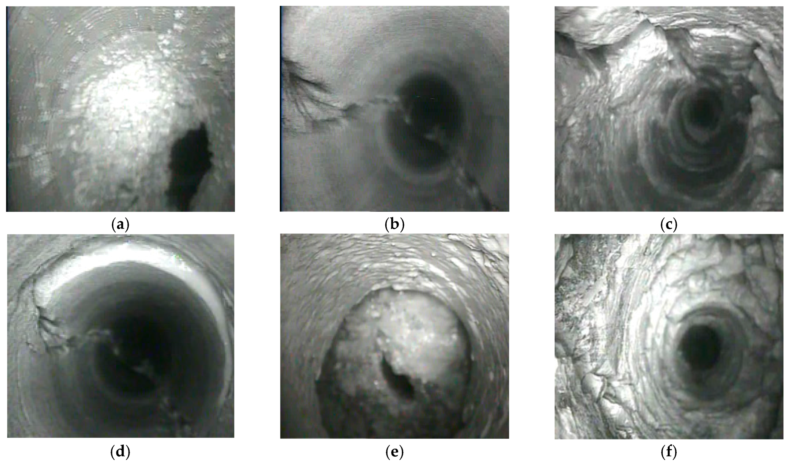
3.2.2. Strata Movement and Fracture Propagation in Borehole #2

Borehole #2 was drilled from 26 March 2013 to 30 April 2013. The drill core was relatively intact (with a few exceptions), and the core recovery rate exceeds 80%. The characteristics of overburden movement and crack development in borehole #2 were similar to that of borehole #1.
When the working face was 87.5 m away from borehole #2, cracks (Figure 9a) first appeared in the area around borehole #2 and its size and quantity increased as the working face moved forward. Then the epipedon deformation was observed (Figure 9b). Whereafter slight damage appeared near the interface between epipedon and rock. Vertical fractures (width = 1–2 mm) and horizontal fractures appeared at depths of 50–60 m. With the working face advancing, the epipedon deformation was exacerbated with exfoliation of the borehole wall (Figure 9c), and the size of fractures on the bedrocks continuously increased.
When the working face was 19.0 m away from the borehole, the loess layer subsided above goaf. However, no obvious mining-induced cracks were observed ahead of the working face, indicating that the strength of the main roof was only strong enough to prevent cracking until the longwall face was right under it. After the breakage of the immediate roof and the main roof, the caving height reached 25.5 m (Figure 10a). Propagation of vertical fractures (Figure 10b) and irregular fractures (Figure 10c) accompanied by dislocations (Figure 10d) were observed, and a bed separation (Figure 10e) between the second sub key stratum and the medium sandstone beneath it was observed. As the working face moved forward, fractures propagated and severe damages of borehole wall (Figure 10f) were observed. When the working face was 56.9 m past the borehole, the second sub key stratum failed. Bed separation, dislocation, and vertical fracture propagation of the stratum above the second sub key stratum were observed. The height of the caving zone increased to 82 m.
When the working face was 80.6 m past the borehole, the third sub key stratum failed. The mining-induced fractures propagated upwards while the density of fractures decreased. The bed separation and dislocation were not very obvious. As the working face moved forward, the borehole that was 207.3 m deep was completely blocked and the strata that were 154.5–197.3 m deep had increasing dislocations. After the working face was 115 m past the borehole, the movement of overburden strata gradually weakened, and slowly sinked under gravity. Part of the bed separation and fractures were closed to compaction. The fractured zone reached the section beneath the main key strata with a maximum height of 137.6 m.

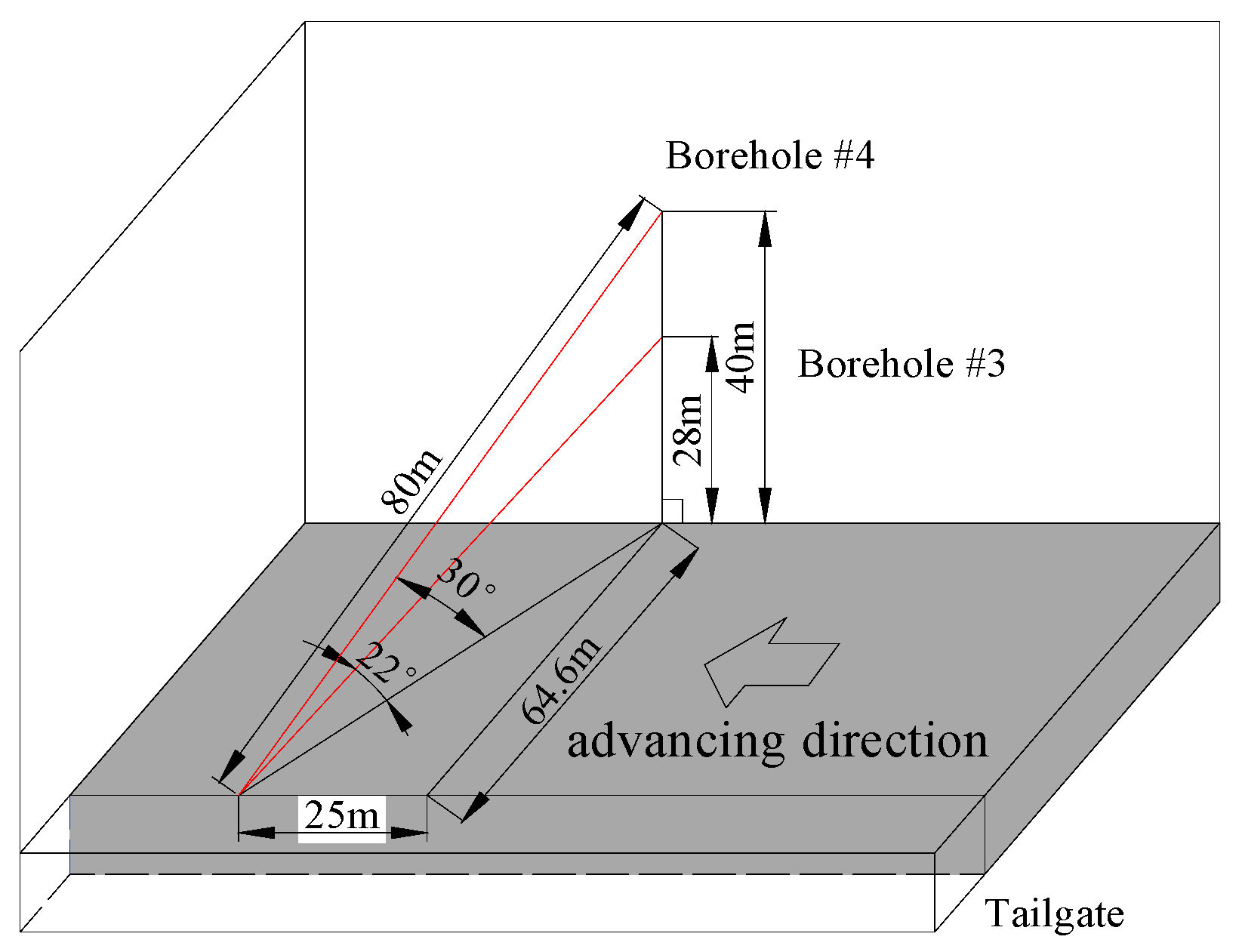
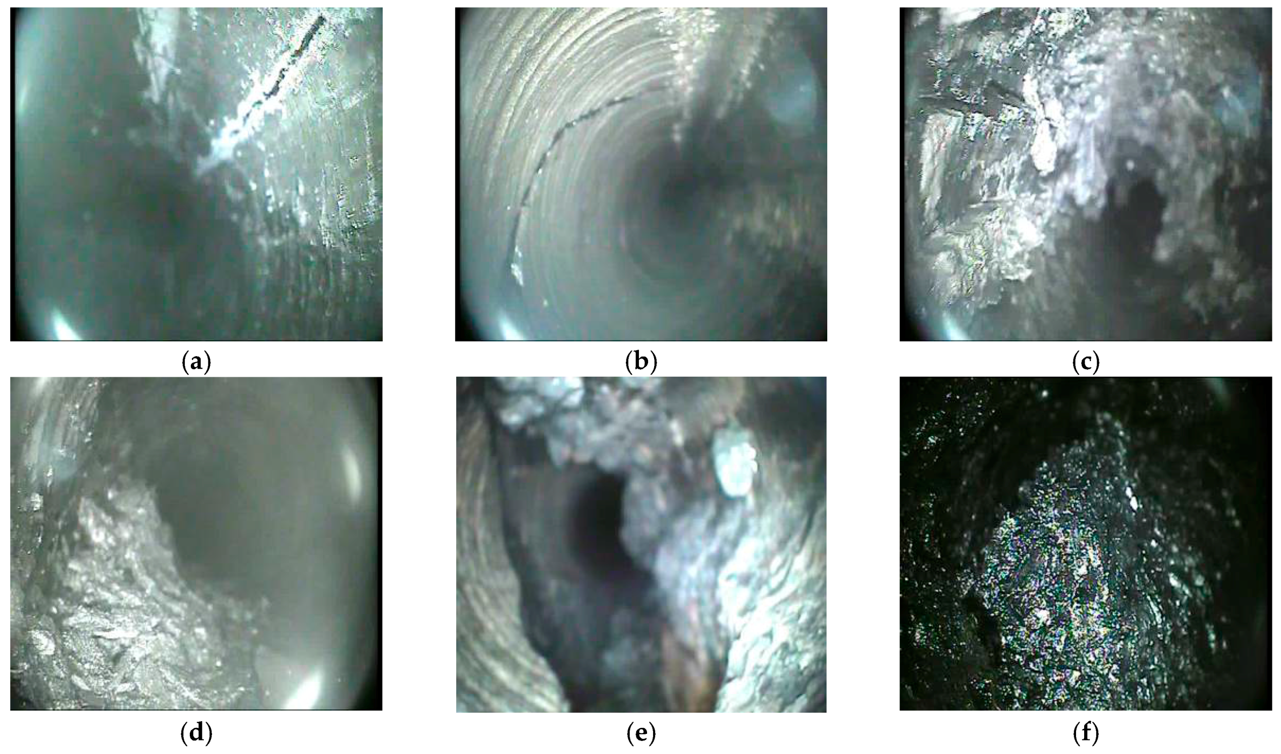
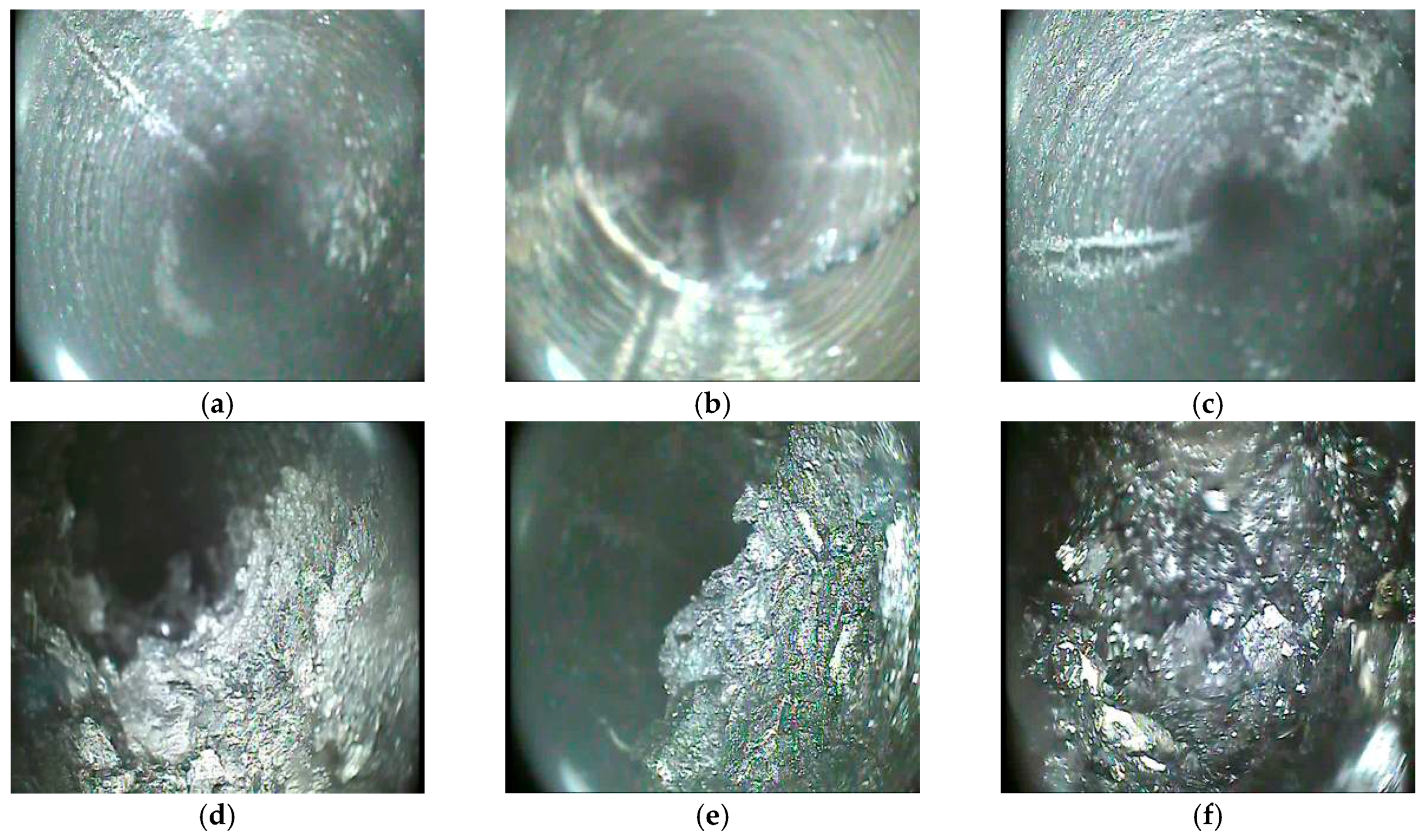
3.3. Underground Observation Borehole

The observation started when the working face was 58.5 m away from the borehole opening and 33.5 m from the hole bottom. No significant fractures were observed in the borehole.
When the working face was 43.5 m away from the borehole opening, axial fractures (length = 3–4 cm, width = 1 mm) first appeared in borehole #3. As the working face moved forward, both density (Figure 11a) and average size of axial fractures increased and local breakage of the coal wall were observed (Figure 11c). When the working face was 19 m away from the borehole opening, the fractures increased up to 20 cm and the height increased to 15–18 m. After that, fracture propagation was significantly accelerated and the maximum fracture exceeded 50 cm. Irregular fractures were observed (Figure 11b), significant wall breakage were observed, and quantity and size of crushed coal in the borehole increased (Figure 11d). Half of the cross section of the borehole was occupied by crushed coal, indicating that the working face had significant effects from mining activities. Additionally, the fractured zone spread to 20–22 m.
When the working face was 11.1 m away from the borehole opening, severe coal wall damages and considerable crushed coal were observed. The observation borehole was significantly damaged, resulting in severe deformations (Figure 11e). The camera was stuck at the location 1.9 m behind the working face and 14.5 m above the channel roof. Dislocations caused by the roof caving into the goaf were observed on the borehole. The height of the caved zone was 15–18 m. During the six-day idling period, the borehole #3 was blocked by crushed coal (Figure 11f) that was located 20.9 m from the opening.
When the working face was 19 m away from the borehole opening, axial fractures were observed in the borehole #4 (Figure 12a). During the four-day idling period, the density of axial fractures increased, while damages of the coal wall were not affected. The propagation of fractures during this period can be attributed to the fact that propagations of mining-induced fractures were slightly behind the roof caving. The height of the water-conducting fracture was 17–19 m.
With the working face advancing, the density of axial fractures increased and the maximum length reached 35 cm. Irregular fractures were observed (Figure 12b) and damages of the coal wall (Figure 10d) were exacerbated. The fractured zone propagated upwards and the height was 20–23 m. Then one axial fractures reached 60 cm in length. Deep fractures propagated along the internal wall (Figure 12c). Observations in the six-day idling period revealed severe damages of the coal wall and considerable crushed coal in the borehole. Deformations of the borehole were observed at a depth of 58.5 m. This location was 7.2 m behind the working face and 29.3 m above the roadway roof. It can be concluded that the borehole was significantly affected by mining activities. The height of the fractured zone reached 25–27 m. When the working face was 5.6 m away from the borehole opening, breakage of the coal wall was exacerbated and the borehole was blocked by crushed coal at a depth of 13.5 m (Figure 12f).

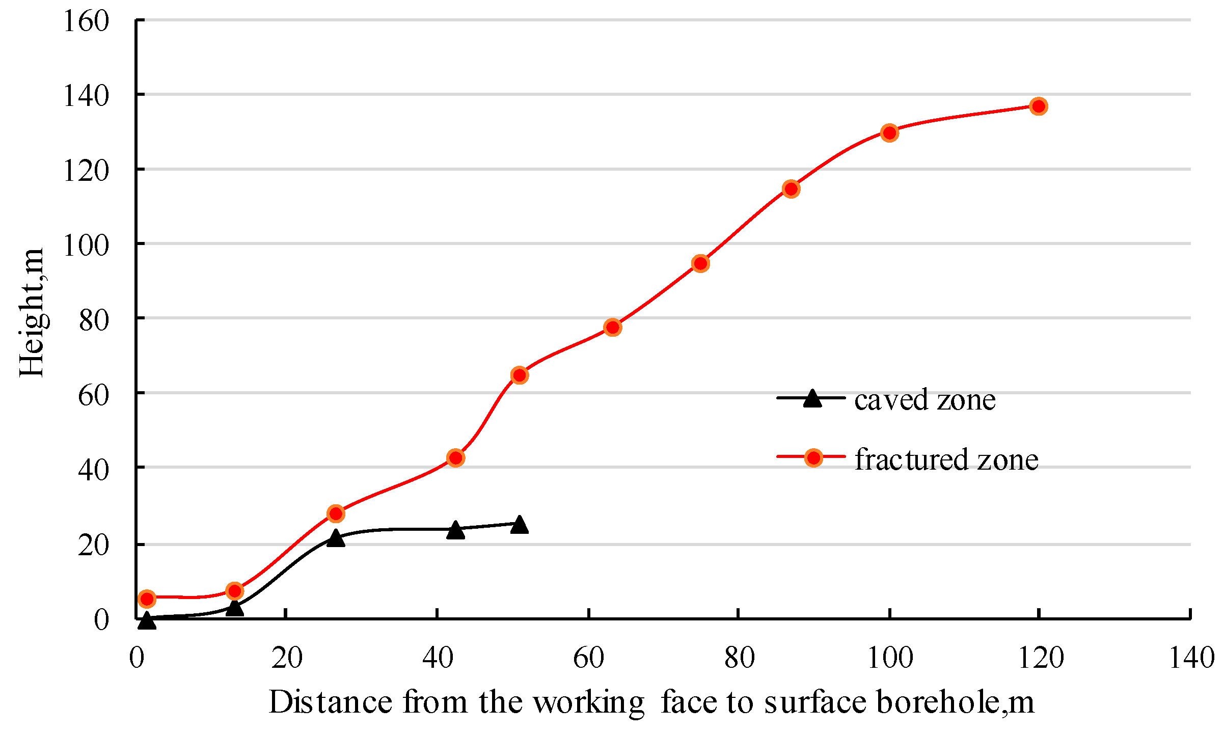
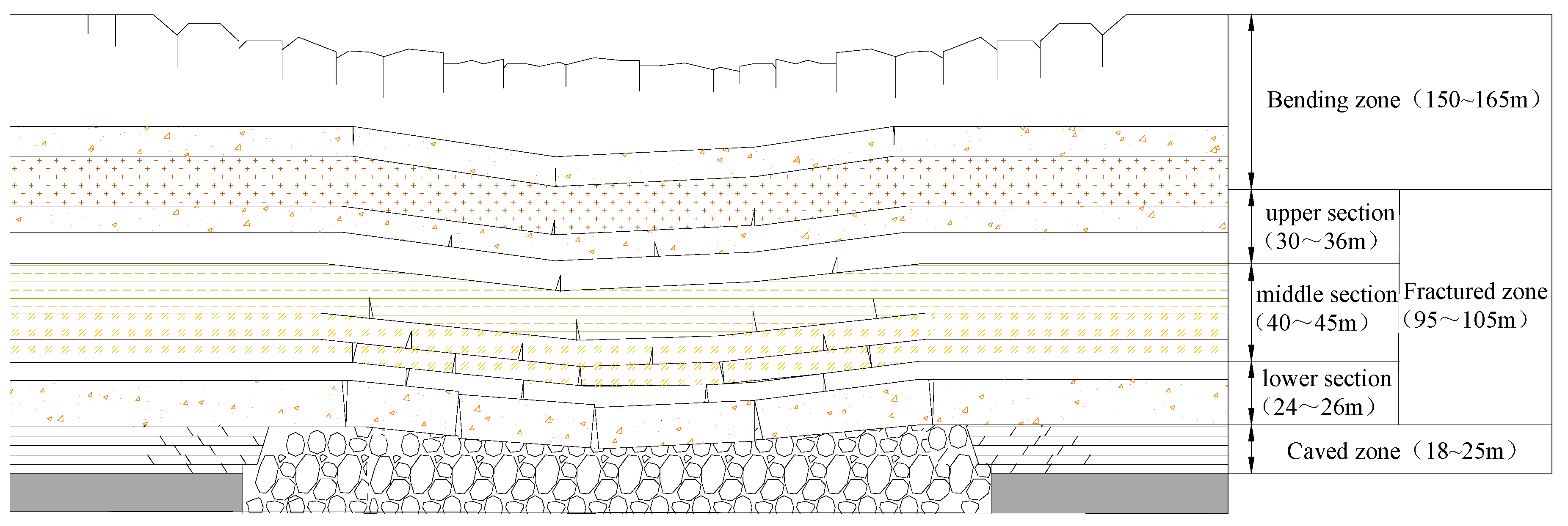
3.4. Heights of Caved Zone and Fractured Zone

The heights change of caved zone and fractured zone in the boreholes during the mining prosess is shown in Figure 13. The cutting and caving heights of panel 20105 were 3.0 and 3.2 m, respectively; the height of the fractured zone was 120–137.6 m (see Table 1). The height of the caved zone was 21.6–25.5 m, while the height of the caved zone in borehole #1’ was not obtained as it didn’t reach the coal seam. The heights of the caved zone and fractured zone in boreholes #3 and #4 were 18.5 and 30 m, respectively. Notably, the measured heights of caved zone and fractured zone appeared to be smaller than the actual values due to the early deformations and blocking in the underground boreholes caused by the abutment pressure. The measured heights of the caved zone and the fractured zone were 2.9–4.11 and 19.35–22.19 times the mining height.

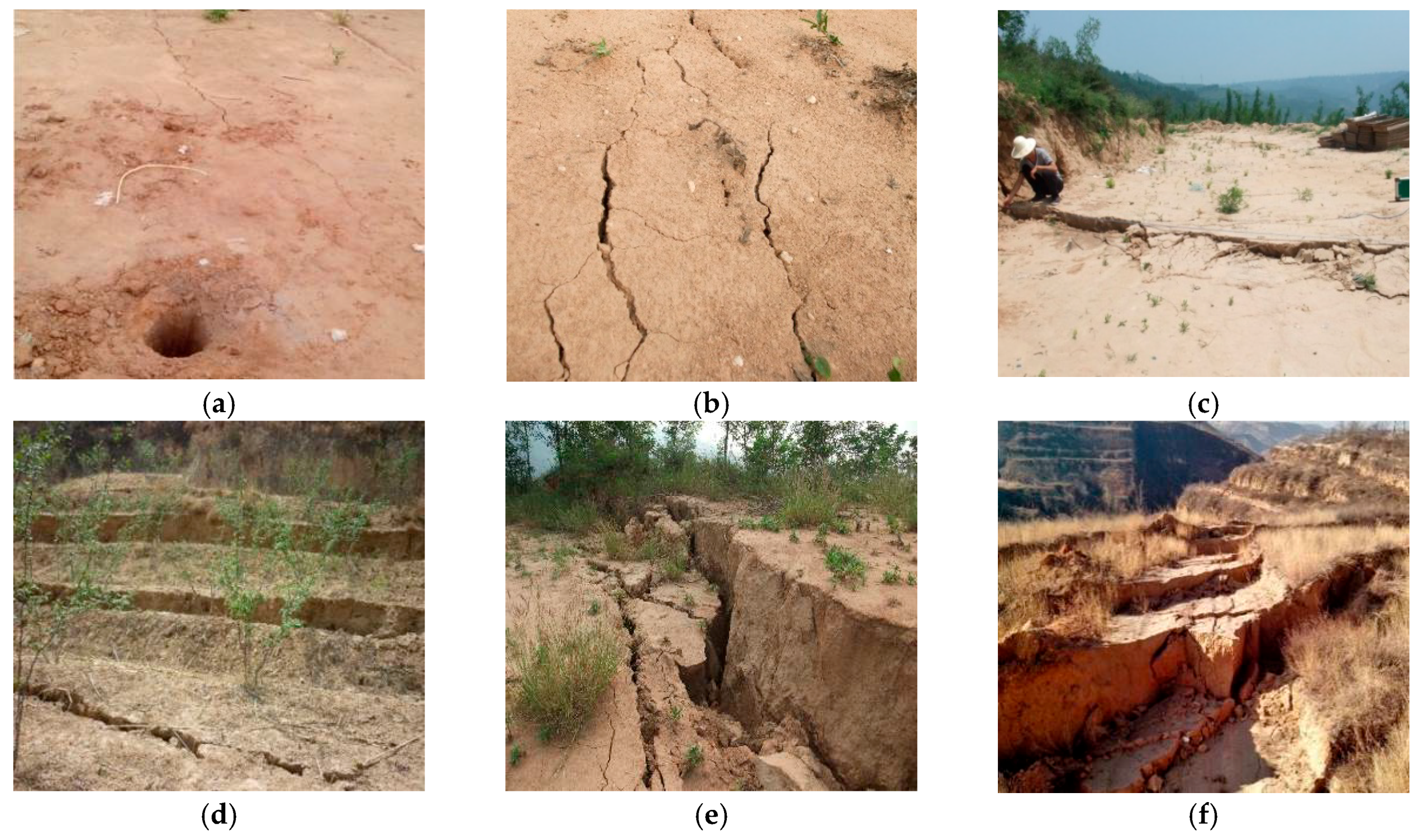
3.5. Ground Surface Subsidence

When the working face was 96.7 m away from the surface borehole, fractures that are parallel to the working face inclination were first observed in the vicinity of the borehole. The advance affecting range of mining was approximately 100 m, and the movable basin area significantly exceeded the mining area. Based on the advance affecting range and mining depth, it is deduced that the advance affecting angle was 71°. As the working face moved forward, the quantity and size of cracks increased further.
When the working face was 29.2 m ahead of the surface borehole, step subsidence appeared in the vicinity of the borehole. The ground surface subsided gradually and continuously. After the mining process, severe damages to the ground surface and step subsidence (maximum subsidence = 4.2 m) were observed, and surface cracks were distributed all over the goaf. The inter-fracture and inter-step distances varied from 1.0 to 6.2 m. The process of the surface subsidence around boreholes was shown in Figure 14.

4. Discussion

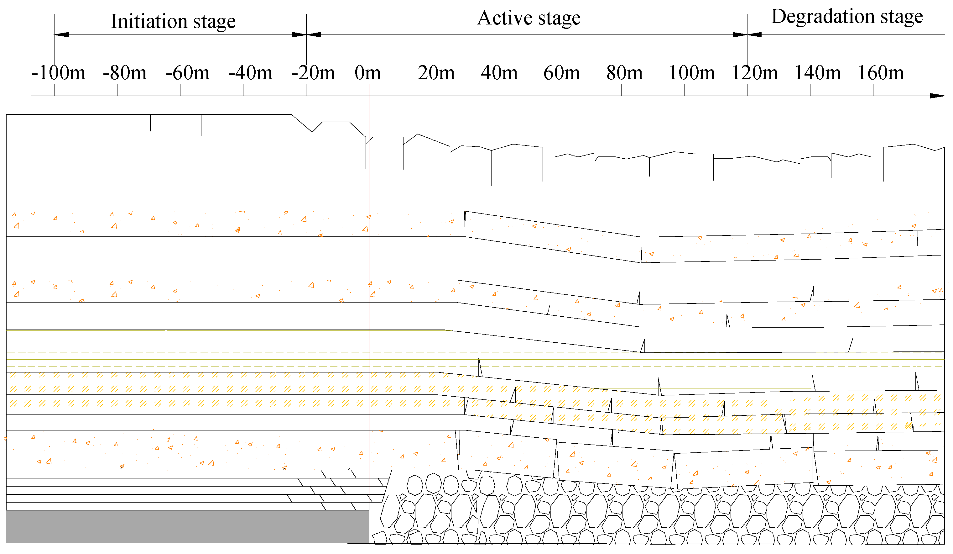
4.1. Movement of Overburden Strata and Fracture Propagation

Roof caving, as well as separation and dislocation, were observed as a result of underground mining. Mining-induced fractures were propagated and overburden strata movement was transferred upwards to the ground surface in this process, resulting in surface deformation. Eventually, the movable basin area exceeded the mined-out area. Based on the differences of surface subsidence velocity, extent of strata movement and propagation of fractures, the whole process can be divided into three stages (Figure 15):
(a)
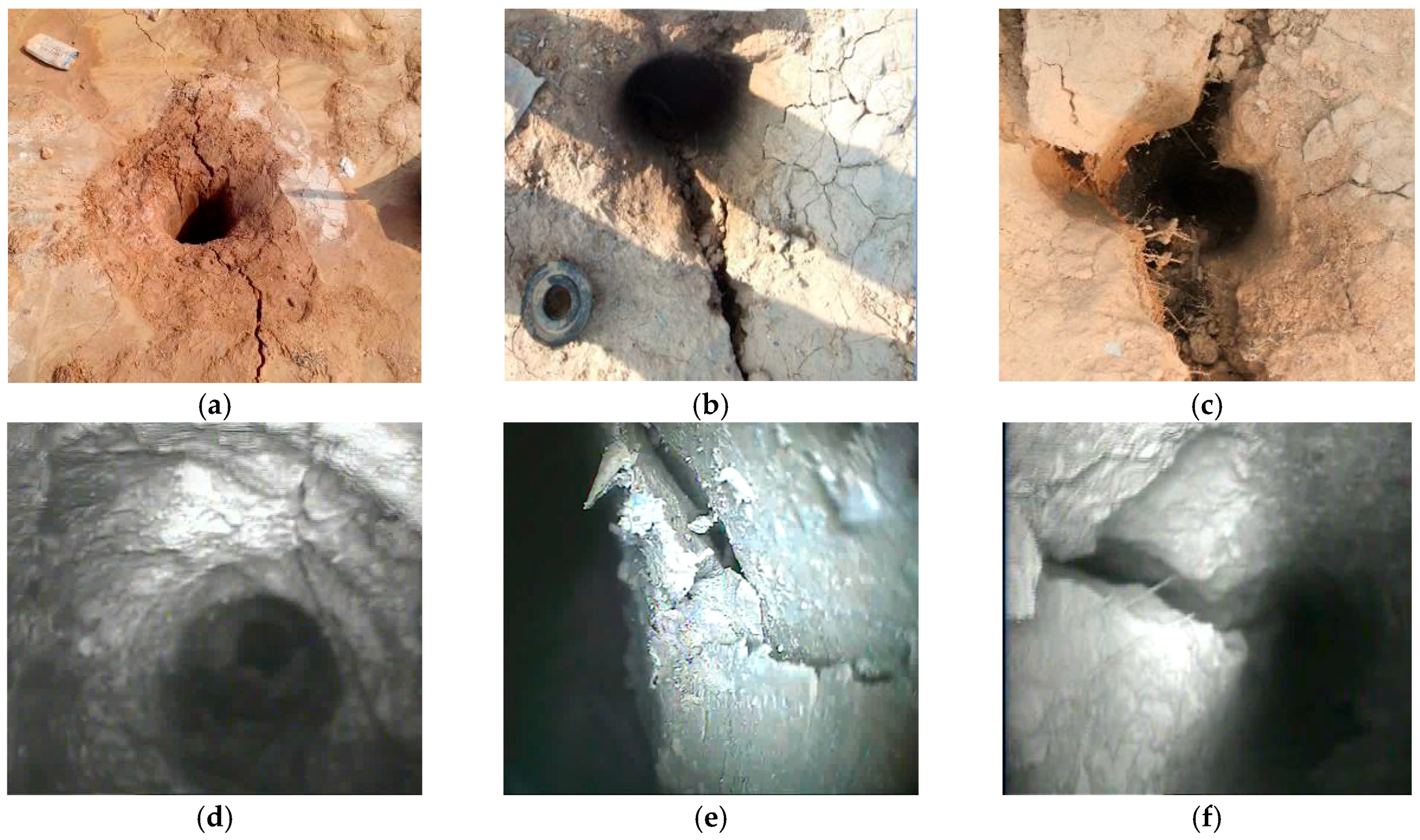
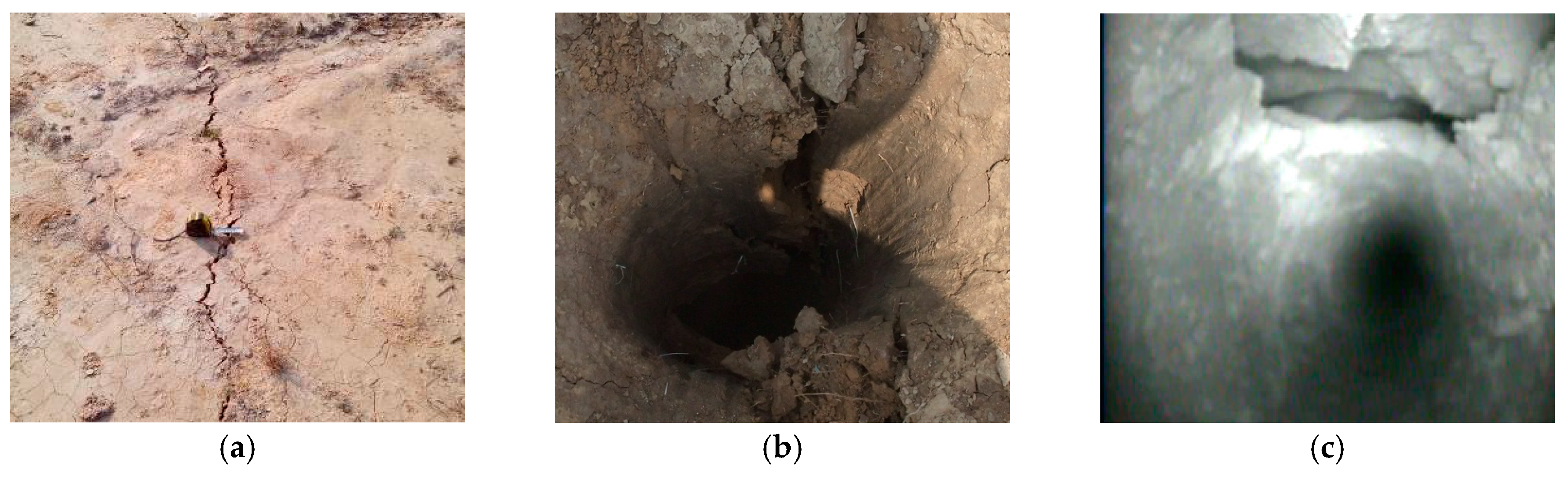
Initiation stage: This stage started when the working face was 100 m away from the borehole and ended when the working face was 20 m away from the borehole. This stage was characterized by cracks distributed on the ground surface, and fractures appeared on the loess layer and strata beneath it. The density and average size of these cracks increased as the working face moved forward. Surface deformation and local borehole wall exfoliation were observed. Additionally, axial and circular fractures were observed on near-surface strata, while deep strata were not significantly affected.
(b)
Active stage: This stage started when the working face was 20 m away from the borehole and ended when the working face was 120 m past the borehole. Propagation of fractures in the overburden strata and movement of the ground surface were significantly accelerated. Mining-induced fractures appeared in the coal and rock ahead of working face within a certain range. When the working face reached the borehole, step subsidence was observed, resulting in severe surface ground deformation. Large-sized fractures and local damages were observed in the bedrocks beneath the epipedon. Separation and dislocation of the overburden strata were observed after failures of the immediate roof and main roof, and mining-induced fractures propagated. The overburden movement, which was characterized by the movement of the key strata, was transferred upwards to the ground surface gradually.
(c)
Degradation stage: This stage started when the working face was 120 m past the borehole. During this stage, the movement of the overburdened strata degraded (there was a slow subsidence due to gravitation). The bed separation and fractures that had developed in the overburden strata were partially closed to compaction and the rate of surface deformation slowed down. Surface cracks and step subsidence were partially mitigated.
It should be pointed out that the duration of each stage varies as a result of geological conditions (e.g., coal seam thickness, depth, and overburden strata properties) of the mining area and mining conditions (mining depth and moving rate of the working face).

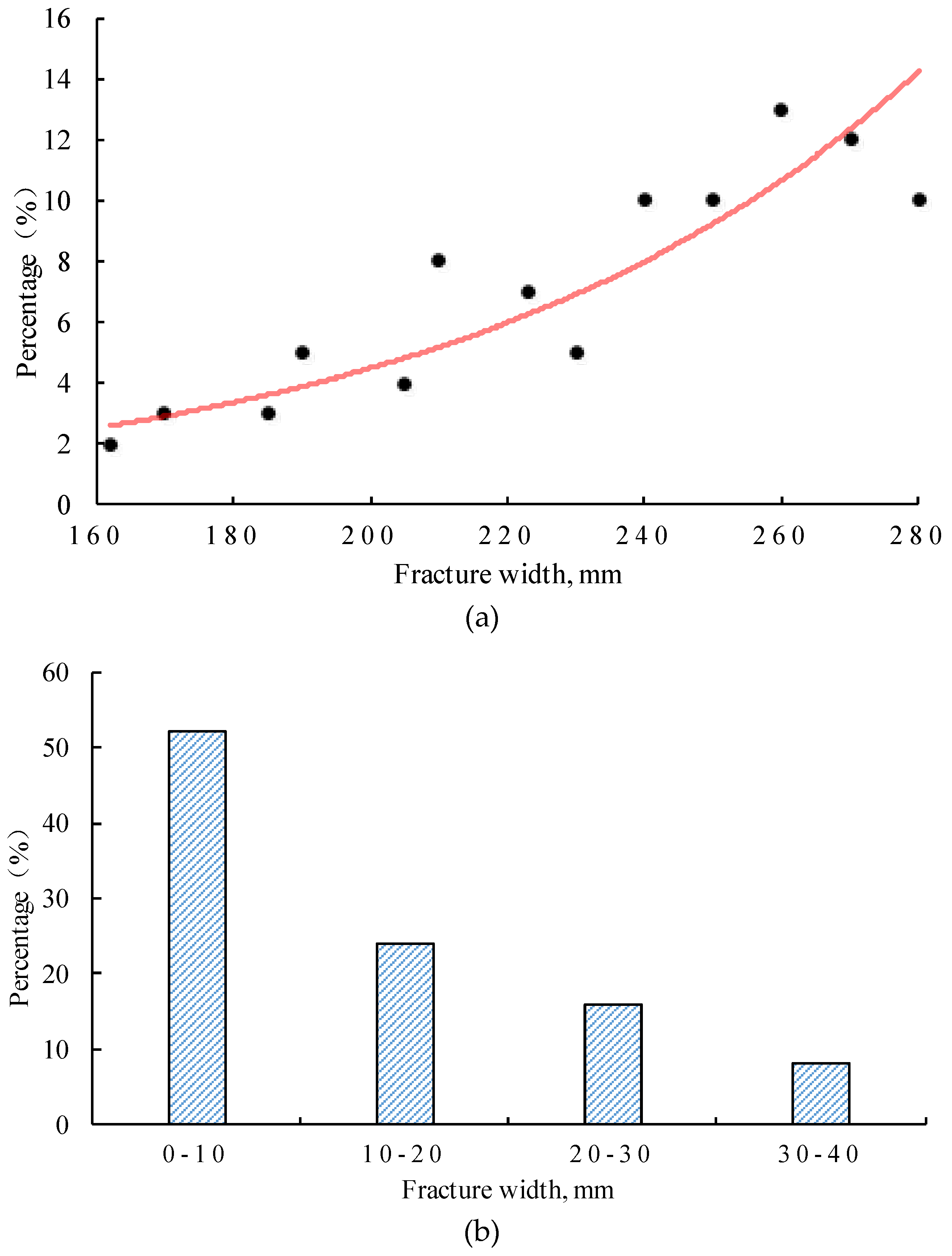
4.2. Distribution of Fractures in the Overburden Strata

Borehole television approach can be used not only to reveal the conditions in the borehole for qualitative identification, but also to obtain pertinent information for quantitative analysis, especially for fracture number, fracture angle and fracture width. In this field measurement, there are 106 fractures totally in the surface boreholes, removing the fractures that were induced during the drilling.
The number of mining-induced fractures can reflect the degree of influence by mining to the rock mass. As shown in Figure 16a, with the increase of drilling depth, the degree of mining influence deepening, fracture number has increased dramatically. The width of fractures reflects the propagation degree. As seen in Figure 16b, the fracture number decreased with the increase of width. Fractures with width between 0 and 20.0 mm account for 76% of fractures, which proves that fractures are mainly of low width. As shown in Figure 16c, the number of fractures at all orientations was relatively average, the interval of 40°–90° accounted for 62%. It can be concluded that most of the mining-induced fractures are vertically oriented.
The fractured zone can be divided into three parts: rock blocks, through-going vertical fractures and horizontal fractures caused by bedding layer separation. According to the different attributes, with the field observations, we confirm the range of the three parts (see Figure 17). In most cases, fractures in the bending subsidence zone exhibited small apertures. However, fractures with large apertures were also observed due to the limited tensile strength of certain strata, especially those near the ground surface (large fractures and step subsidence).

5. Conclusions

(1)
Field observations showed that the overburden strata generally experienced the phases of roof caving, generation of fracture, bed separation, dislocations, fracture propagation, surface subsidence, closing of fractures. The entire mining process can be divided into the initiation stage, the active stage, and the degradation stage according to activities of the overburden strata and propagation of mining-induced fractures.
(2)
The advance affecting range and angle of the working face were 96.7 m and 71°, respectively. The caved zone height is 2.9–4.11 times of the mining height, and the length of fractured zone is 19.35–22.19 times of the mining height. The height range of three parts in fractured zone is 24–26, 40–45, 30–35 m. Significant fractures were observed in the bending zone. Step subsidence and cracks, which indicate severe damages, were observed on the ground surface above goaf.
(3)
The borehole television approach is an effective and rapid way to observe the dynamic morphology of boreholes and facilitate the investigation of temporal and spatial evolution of mining-induced fractures in overburden strata during the mining process. Nevertheless, application of this approach has been limited by several issues. For instance, the resolution of the obtained images may be significantly affected by air humidity in the underground borehole. When the air is very damp in the boreholes, the observed images are often blurred. Also, observation cannot be achieved in the presence of wall damage or horizontal dislocation of the borehole, which lead to collapse and blockage.

Acknowledgments

The research is financially supported by the National Basic Research Program of China (No. 2015CB251600) and the National Natural Science Foundation of China (Nos. 51404254 and 51474206). We wish to thank the Wangjialing Coal Mine for supporting to conduct this important study, as well as Yang Zhang, Shenglong Zhang, Jiang Wen for the assistance of data collection.

Author Contributions

All the authors contributed to publishing this paper. Hongzhi Wang performed the technological development and prepared and edited the manuscript. Dongsheng Zhang revised and reviewed the manuscript. Xufeng Wang, Wei Zhang partially participated in the literature research and data processing during the research process.

Conflicts of Interest

The authors declare no conflict of interest.

References

  1. Qian, M.G.; Shi, P.W.; Xu, J.L. Mining Pressure and Strata Control; China University of Mining and Technology Press: Xuzhou, China, 2010; pp. 98–101. (In Chinese) [Google Scholar]
  2. Zhang, D.S.; Fan, G.W.; Ma, L.Q.; Wang, X.F. Aquifer protection during longwall mining of shallow coal seams: A case study in the Shendong Coalfield of China. Int. J. Coal Geol. 2011, 86, 190–196. [Google Scholar] [CrossRef]
  3. Ma, L.Q.; Du, X.; Wang, F.; Liang, J.M. Water-preserved mining technology for shallow buried coal seam in ecologically-vulnerable coal field: A case study in the Shendong coal field of China. Disaster Adv. 2013, 6, 268–278. [Google Scholar]
  4. Fan, G.W.; Zhang, D.S.; Zhai, D.Y.; Wang, X.F.; Lu, X. Laws and mechanisms of slope movement due to shallow buried coal seam mining underground gully. J. Coal Sci. Eng. 2009, 15, 346–350. [Google Scholar] [CrossRef]
  5. Lai, X.P.; Cai, M.F.; Xie, M.W. In situ monitoring and analysis of rock mass behavior prior to collapse of the main transport roadway in Linglong Gold Mine, China. Int. J. Rock Mech. Min. Sci. 2006, 43, 640–646. [Google Scholar] [CrossRef]
  6. Palchik, V. Localization of mining-induced horizontal fractures along rock layer interfaces inoverburden: Field measurements and prediction. Environ. Geol. 2005, 48, 68–80. [Google Scholar] [CrossRef]
  7. Palchik, V. Formation of fractured zones in overburden due to longwall mining. Environ. Geol. 2003, 44, 28–38. [Google Scholar]
  8. Palchik, V. Experimental investigation of apertures of mining-induced horizontal fractures. Int. J. Rock Mech. Min. 2010, 47, 502–508. [Google Scholar] [CrossRef]
  9. Zhang, S.T.; Liu, Y. A simple and efficient way to detect the mining induced water-conducting fractured zone in overlying strata. Energy Procedia 2012, 16, 70–75. [Google Scholar] [CrossRef]
  10. Yu, J.C.; Liu, Z.X.; Yue, J.H.; Liu, S.C. Development and prospect of geophysical technology in deep mining. Prog. Geophys. 2007, 22, 586–592. (In Chinese) [Google Scholar]
  11. Kang, H.P.; Lin, J. Geomechanical tests and their applications in rock anchorage design. In Proceedings of the 11th Congress of the International Society for Rock Mechanics, Lisbon, Portugal, 9–13 July 2007; pp. 303–305.
  12. Kang, H.P.; Si, L.P.; Su, B. Borehole observation methods in coal and rock mass and their applications. J. China Coal Soc. 2010, 35, 1949–1956. (In Chinese) [Google Scholar]
  13. Wang, C.Y.; Law, K.T. Review of borehole camera technology. Chin. J. Rock Mech. Eng. 2005, 24, 3440–3448. (In Chinese) [Google Scholar]
  14. Han, Z.Q.; Wang, C.Y.; Hu, S. Digital borehole camera technology and its applications in mining geology exploration. In Proceedings of the 24th International Mining Congress and Exhibition of Turkey, Antalya, Turkey, 14–17 April 2015; pp. 287–290.
  15. Han, Z.Q.; Wang, C.Y.; Liu, S.B.; Zhu, H.Y. Research on connectivity of deep ore-lodes of borehole based on digital borehole camera. Disaster Adv. 2013, 6, 41–46. [Google Scholar]
  16. Han, Z.Q.; Wang, C.Y.; Zhu, H.Y. Research on deep joints and lode extension based on digital borehole camera technology. Pol. Marit. Res. 2015, 22, 10–14. [Google Scholar] [CrossRef]
  17. Tan, Y.L.; Zhao, T.B.; Xiao, Y.X. In situ investigations of failure zone of floor strata in mining close distance coal seams. Int. J. Rock Mech. Min. 2010, 47, 865–870. [Google Scholar] [CrossRef]
  18. Tan, Y.L.; Ning, J.G.; Li, H.T. In situ explorations on zonal disintegration of roof strata in deep coalmines. Int. J. Rock Mech. Min. 2012, 49, 113–124. [Google Scholar] [CrossRef]
  19. Tan, Y.L.; Yu, F.H.; Chen, L. A new approach for predicting bedding separation of roof strata in underground coalmines. Int. J. Rock Mech. Min. 2013, 61, 183–188. [Google Scholar] [CrossRef]
  20. Xiong, Z.Q.; Wang, C.; Zhang, N.C.; Tao, G.M. A field investigation for overlying strata behavior study during protective seam longwall overmining. Arab. J. Geosci. 2015, 8, 7797–7809. [Google Scholar] [CrossRef]
  21. Zhang, Y.J.; Liu, Z.G.; Guo, D. Study on simulation and monitoring of overburden failure height of multifull-mechanized caving mining. In Proceedings of the International Conference on Mine Hazards Prevention and Control, Qingdao, China, 15–17 October 2010; pp. 548–559.
  22. Gao, B.B.; Wang, X.L.; Zhu, M.L. Dynamic development characteristics of overburden strata ”two-zones” under conditions of compound roof, highly gassy and thick coal seam in full-mechanized top coal caving faces. Chin. J. Rock Mech. Eng. 2012, 31, 3444–3451. (In Chinese) [Google Scholar]
Figure 1. Layout of Panel 20105.
Minerals 07 00035 g001
Figure 2. The layout of the boreholes.
Minerals 07 00035 g002
Figure 3. Stratigraphic columns of surface holes: (a) borehole #1; (b) borehole #1’; (c) borehole #2.
Minerals 07 00035 g003aMinerals 07 00035 g003b
Figure 4. Layout schemes of the underground holes.
Minerals 07 00035 g004
Figure 5. TYGD10 stratum borehole monitor.
Minerals 07 00035 g005
Figure 6. Observations in borehole #1: (a) crack at the borehole opening; (b) crack propagation; (c) borehole opening deformation; (d) fractures in the loess layer; (e) fracture propagation; (f) exfoliation.
Minerals 07 00035 g006
Figure 7. Observations in borehole #1: (a) vertical fracture; (b) irregular fracture; (c) damages of borehole wall; (d) strata caving; (e) dislocations; (f) severe damages of borehole wall.
Minerals 07 00035 g007
Figure 8. Observations in borehole #1’: (a) burial depth of 50–100 m; (b) burial depth of 100–170 m; (c) burial depth of 170–200 m; (d) burial depth of 200–210 m; (e) burial depth of 210–220 m; (f) burial depth of 220–230 m.
Minerals 07 00035 g008
Figure 9. Observations in borehole #2: (a) crack near the borehole opening; (b) epipedon deformation; (c) exfoliation of the borehole wall.
Minerals 07 00035 g009
Figure 10. Observations in borehole #1: (a) strata caving; (b) vertical fracture; (c) irregular fracture; (d) dislocations ; (e) bed separation; (f) damages of borehole wall.
Minerals 07 00035 g010
Figure 11. Observations in borehole #3: (a) axial fractures; (b) irregular fractures; (c) wall breakage; (d) crushed coal; (e) deformations; (f) blocked by crushed coal.
Minerals 07 00035 g011
Figure 12. Observations in borehole #4: (a) axial fractures; (b) irregular fractures; (c) fracture propagation; (d) wall breakage; (e) crushed coal; (f) blocked by crushed coal.
Minerals 07 00035 g012
Figure 13. Change of the caved zone and fractured zone in boreholes.
Minerals 07 00035 g013
Figure 14. Surface subsidence around boreholes: (a) cracks; (b) quantity of cracks increased; (c) surface subsidence; (d) step subsidence; (e) subsidence increased; (f) final subsidence.
Minerals 07 00035 g014
Figure 15. Three stages of the overburden movement.
Minerals 07 00035 g015
Figure 16. Fracture attributes: (a) number of fractures versus borehole depth; (b) proportion of fractures versus fracture width; (c) proportion of fractures versus fracture angle.
Minerals 07 00035 g016aMinerals 07 00035 g016b
Figure 17. Distribution of fractures in the overburden strata.
Minerals 07 00035 g017
Table 1. The height of caved zone and fractured zone.
ZoneBorehole #1Borehole #1’Borehole #2Borehole #3Borehole #4
Height/mRatio to Mining HeightHeight/mRatio to Mining HeightHeight/mRatio to Mining HeightHeight/mRatio to Mining HeightHeight/mRatio to Mining Height
Caved zone21.63.48--25.54.1118.52.9818.02.90
Fractured zone125.320.2112019.35137.622.19----

