Article

Demonstration Plant Equipment Design and Scale-Up from Pilot Plant of a Leaching and Solvent Extraction Process

by
Fátima Arroyo
*,
Constantino Fernández-Pereira
and
Pilar Bermejo
School of Engineering, Chemical and Environmental Engineering Department, University of Seville, Camino de los Descubrimientos, Seville 41092, Spain
*
Author to whom correspondence should be addressed.
Minerals 2015, 5(2), 298-313; https://doi.org/10.3390/min5020298
Submission received: 13 February 2015 / Revised: 13 May 2015 / Accepted: 19 May 2015 / Published: 28 May 2015

Abstract

:
Germanium recovery from coal fly ash by hydrometallurgical procedures was studied at the pilot scale (5 kg of fly ash/h). Results were used to design the equipment of a demonstration-sized plant (200 kg of fly ash/h). The process is based on hydrometallurgical operations: firstly a germanium extraction from fly ash by leaching and a consequent Ge separation from the other elements present in the solution by solvent extraction procedures. Based on the experimental results, mass balances and McCabe-Thiele diagrams were applied to determine the number of steps of the solvent extraction stage. Different arrangements have been studied and a countercurrent process with three steps in extraction and six steps in elution was defined. A residence time of 5 min was fixed in both the extraction and elution stages. Volumetric ratios in extraction and stripping were: aqueous phase/organic phase = 5 and organic phase/stripping phase = 5, so a concentration factor of 25 is achieved. Mixers and decanters were completely defined. The maximum extracted and eluted germanium was estimated and a global efficiency of 94% was achieved. The cost-effectiveness of the equipment was estimated using the Lang factors.

1. Introduction

Germanium is not very abundant in the Earth’s crust, occurring only at a concentration of 1 to 7 ppm [1]. It is widely dispersed in nature, sometimes as a pure metal in association with more abundant elements (such as Zn and its minerals) and as germanium oxide. By far, the most important application of germanium is in the manufacturing of semiconductors, but innovative uses for germanium in new and high technological industrial applications have led to an increase in its price, so it is currently more attractive to process raw materials with low contents of germanium (sometimes only a few ppm) and considerable quantities of other elements.
Worldwide, about 30% of the total germanium consumed comes from recycled materials. With regard to “new” germanium production, the main sources are the zinc and copper ores, from which germanium is obtained as a byproduct. Nevertheless, due to the uses for germanium in new and high technological industrial applications, germanium metal and oxide have increased in price (1800 $/kg of germanium metal in September 2013) [2], and alternative sources such as combustion [3] and gasification [4] coal fly ashes. When the coal is gasified under proper conditions the fly ash (FA) can reach germanium contents ten times higher than the germanium content in the original coal [5].
Fly ash valorization poses a significant economic and environmental burden, but can also be viewed as a resource of huge potential. There are a few approaches nowadays for FA valorization aside from building purposes since it has a potential role as a value-added product in material preparation (e.g., ceramics), recovery of materials (e.g., metals) and agricultural applications (e.g., as bioremediation). Nevertheless, in most cases, reported work to date in this area has been of theoretical research or laboratory scale and further development work is needed.
Germanium occurs in relatively high contents in the fly ash (FA) produced in the Puertollano (Spain) Integrated Gasification Combined Cycle (IGCC) power plant. Nowadays, the 335 MW (ISO) Puertollano IGCC plant is the largest worldwide gasification plant in operation. In this plant, a 50:50 local coal/pet-coke blend is gasified with 2%–4% w/w of limestone (fluxing agent), in a pressurized entrained flow gasifier, at 1600 °C and 25 bars. The Puertollano coal is a high volatile bituminous coal, rich in a number of metals [6], while pet-coke, supplied by an oil refinery is generally a C-rich material with high concentrations of S, V and Ni [7]. The high slag/FA ratio (90:10 or 85:15) produced in the Puertollano IGCC plant is the opposite with respect to that of conventional pulverized coal combustion plants (20:80). Germanium is completely volatilized during gasification and subsequently condenses during gas cooling to form sulphides and oxide species [8]. The complete volatilization of these elements is caused by the organic occurrence of Ge and the main sulphide affinity of Pb, Ga and Bi in the Puertollano coal [8]. The high calcophile affinity of these elements in reducing conditions account for the formation of sulphide species, such as galena for Pb, GeS and GeS2 for Ge or substituting for Zn in spharelite/wurtzite lattices for Ga, and the subsequent high retention of these elements in fly ash [8] (Table 1).
Germanium occurs in FA mainly (up to 91% w/w) as water-soluble hexagonal-GeO2 and GeS2 (solubility: 4.5 g/L) and GeS (solubility: 2.4 g/L). Minor proportions (up to 20%) of Ge may occur as low soluble species (tetragonal-GeO2 or GeO4 tetrahedral).
Many conventional techniques have been developed to separate germanium from other elements contained in leachates, including precipitation with tannin, distillation of GeCl4 [9], flotation of a Ge complex [10,11] adsorption onto activated carbon [12], precipitation [13], solvent extraction [14,15] and sorption onto chelating exchange resins [16,17].
Table 1. Production date, limestone dosage (%), coal/pet-coke ratio and Ge content (mg/kg) in fly ash samples selected for Ge and Ga extraction tests [8].
Fly AshDateLimestone (%)Coal/Pet-Coke DoseGe Content (mg/kg)
FA#211/09/19994.150:50347
FA#724/10/20002.650:50244
FA#10--/11/20022.250:50356
FA#1320/10/20052.550:50319
FA#1503/06/20082.750:50235
FA#1630/06/20082.850:50268
FA#1702/07/20082.850:50228
FA#1819/09/20082.450:50174
The solvent extraction (SX) method for the recovery of germanium from fly ash is based on the germanium-1, 2-dihydroxybenzene (catechol, CAT) (C6O2H6) chelate and the subsequent extraction of the complex using tri-n-octylamine (TOA) ((C8H17)3N) and stripping with alkaline solutions. The equilibrium extraction and stripping are given by the following equations respectively:
2 ( C 8 H 17 ) 3 N ( org ) + Ge ( OH ) 4 ( aq ) o + 3 ( C 6 O 2 H 6 ) ( aq ) ( ( C 8 H 17 ) 3 NH ) 2 Ge ( C 6 O 2 H 4 ) 3 ( org ) + 4 H 2 O
Once the Ge is in the organic phase, two stripping possibilities are apparently possible, because the ternary complex is not stable in strong acidic or alkaline solutions [18]. Alkaline stripping is shown in Equation (2).
( ( C 8 H 17 ) 3 NH ) 2 Ge ( C 6 O 2 H 4 ) 3 ( org ) + 2 O H - ( aq ) 2 ( C 8 H 17 ) 3 N ( org ) + Ge ( C 6 O 2 H 6 ) 3 ( aq ) + 2 H 2 O
The last step of a hydrometallurgy process for the recovery of germanium from FA consisted in precipitation processes for germanium from the Ge-bearing solutions. A possible precipitation is based on precipitating Ge with cetyltrimethylammonium bromide (CTAB) and catechol [19]. The Ge-CAT complex has a high solubility in water probably due to its polarity, but when CTAB is added to an aqueous solution that contains the Ge-CAT complex, the CTA+ cation and the Ge-CAT complex form a heavy ion pair that precipitates. The ion-pair could be formed as follows if the stoichiometric ratio of reagents is Ge:CAT:CTAB 1:3:2 [19,20].
2C 19 H 42 NBr + [Ge(C 6 H 4 O 2 ) 3 ] 2-  (C 19 H 42 N) 2 Ge(C 6 H 4 O 2 ) 3  + 2Br +
The Ge precipitate can be roasted (at temperature >600 °C) rendering an end product in the form of germanium dioxide. The mechanism for the decomposition of the germanium-complex has been published previously [19,20].
A pilot plant operation is usually needed to generate information about the behavior of the system to be used in the design of larger facilities; therefore, a pilot plant was designed to test this hydrometallurgical method and to obtain operating conditions and some data necessary for a future larger plant design. The main points related to equipment design of the pilot plant were continuity and versatility [20], taking into account the scaling up from the pilot scale to a demonstration level.
This paper shows the design of a demonstration plant from experiments carried out at the pilot scale regarding leaching and SX process.

2. Process and Pilot Plant

The pilot plant design was based on the results obtained at laboratory scale [13,14,21] and it was operated in a continuous mode. A schematic arrangement of the flow configuration is illustrated in Figure 1, and pilot plant design and experimentation have been previously published [22]. The pilot plant comprised two main stages: germanium extraction from FA (leaching with water) and separation of germanium from other elements dissolved in the leachate (L) (interferences). After water leaching, wet fly ash and leachate are separated in a vacuum filter. Catechol is added to leachate and the pregnant solution (leachate + CAT + H2SO4) is contacted in a mixer-settler unit with an organic phase carrying an extracting agent for Ge. After extraction, the aqueous phase (AP) and organic phase (OP) are allowed to separate in the settler. The organic solution from the extraction stage feeds the stripping mixer-settler where it is contacted with an alkaline stripping solution (SP), which reverses the extraction process.
Figure 1. Pilot plant flow sheet scheme.
Minerals 05 00298 g001
The pilot plant mass balance was performed with a feedstock of 5 kg/h of fly ash, with a theoretical recovery of germanium of 1.3 g/h (as GeO2) [22].
The pilot plant is fed with 5 kg/h of FA and it consists of a leaching reactor unit (100 L), a complex formation tank (30 L), two mixer-settler units, for extraction (mixer: 10 L—settler: 2 L with 120 cm2 of settling area) and stripping (mixer: 3.5 L—settler: 0.8 L with 100 cm2 of settling area) three auxiliary reactors for raffinate discharge and storage (30 L), organic phase preparation (25 L) and germanium-rich final solution storage (10 L), all constructed of stainless steel. Auxiliary dosifiers, tanks, pumps, valves and control devices were also integrated into the process [22].
One fundamental stage of the process was the germanium leaching performed in a reactor with water and FA continuous additions. Some leaching tests with three different L/S ratios (3, 5 and 7) were carried out at laboratory and pilot plant scale [13,14]. At leaching times <6 h, a small increase of germanium extraction was observed with increasing L/S ratio. But taking into account other aspects such as the fluency of the fly ash-water mixture, worse for L/S = 3, or the quantity of liquid residues, higher in the case of L/S = 7, tests performed in the pilot plant confirmed L/S = 5 as the optimum relation in agreement with the laboratory results [13,14]. After the leaching, wet FA and leachate were separated by a vacuum rotary filter [22]. Concerning the SX method, previous results show that the extraction yields achieve 95% after 5 min of residence time when AP/OP = 5 is used [13,14]. Regarding the stripping stage, the germanium stripping yields achieve 98% with a sodium hydroxide solution in 5 min (residence time) for OP/SP = 5 [13,14].
The reutilization of raffinate as leaching solution was studied, and results show the best option in terms of leaching yield. Tests were performed and results are shown in Table 2. A larger amount of raffinate in the leaching solution increased the germanium content in leachate, but if the pH of the leaching solution is very low, the puzzolanity of the fly ash can change, avoiding its reutilization after germanium extraction in many of their current applications [4,21]. Fly ash would also be a residue instead of a by-product so a leaching solution constituted by 75% of raffinate from SX process and 25% of fresh water (Table 2) was selected. With this reutilization, the Ge extraction yield can increase up to 25% compared with the leaching with water due to the low pH and the amount of catechol, so leachates with Ge contents of 50 mg/L can be achieved. Residence time decreased due to catechol and acid effect to 2 h (from 24 h with water leaching).
Table 2. Leaching tests with different raffinate/water ratios and residence times.
Leaching SolutionLeaching Time (h)Ge in Leachate (mg/L)
65% raffinate 35% water1.530
245
640
75% raffinate 25% water1.532
253
646
85% raffinate 15% water1.543
252
649
The return of the organic phase in the SX stage was also studied in the pilot plant trials and results shown that TOA remained in the OP after stripping, so reutilization of OP is possible and extraction yields remained almost constant [21]. Some fresh organic phase diluent and TOA has to be introduced in the system due to evaporation and entrainments in the raffinate losses.

3. Preliminary Mass Balance

The actual FA production of ELCOGAS IGCC Power Plant (Puertollano, Spain) is 2000 kg/h. The demonstration plant was designed for 10% of actual FA production because, for a new process, a conservative scaling factor of 10 is recommended by some authors [23]. The design considered a demonstration plant capacity of 200 kg/h fly ash (10% of 2000 kg/h) with a Ge content of 300–400 ppm (Table 1). In Table 3, the pilot plant and demonstration plant preliminary mass balances are shown.
Table 3. Pilot plant and demonstration plant preliminary mass balance. Ge mass balance.
Main CompoundsFlowUnitsConcentration (mg/L)FlowUnitsGe Total (g)
Fly ashFA5.0kg/h350200kg/h70.0
Leaching solution (W/FA = 5)Fresh water (FW)6.3L/h0250L/h0.0
R recycled (RR)18.8L/h4750L/h3.0
Total25.0L/h-1000L/h3.0
Leachate/Aqueous phaseAP22.4L/h53896L/h46.8
CakeC (FA)5.0kg/h-200kg/h20.7
C (leachate)2.6L/h53104L/h5.5
Total (Wet FA)7.5--300-26.2
Organic phase (AP/OP = 5)Fresh OP (FOP)0.4L/h017.9L/h0.0
ROP (recycled)4.0L/h20161.3L/h3.2
Total4.5L/h-179.2L/h3.2
Organic extractOE4.3L/h259170.2L/h44.0
Losses0.2L/h2599.0L/h2.4
Total4.5L/h-180L/h-
RaffinateResidual raffinate3.7L/h4146L/h0.6
For recycling (RR)18.8L/h4750L/h3.0
Total Raffinate22.4L/h4896L/h3.6
Stripping phase (OE/SP = 5)SP0.9L/h034.0L/h0.0
Aqueous extractAE0.9L/h1243.234.0L/h42.3
Residual organic phaseROP4.0L/h20161.3L/h3.2
Losses0.2L/h209.0L/h0.2
A total of 83.9% of recovered raffinate was reintroduced in the process as leaching agent, and 95% of the organic phase was reintroduced in the process too.
A germanium balance is included, and 61 g/h of GeO2 (equivalent) could be recovered from the 200 kg/h of FA.

4. Demonstration Equipment Design

In the case of the demonstration plant, geometric similitude with pilot plant equipment was maintained. The criteria for the pilot plant equipment design was the simplest as possible, because a hydrometallurgical process for a residue valorization (with a low content of germanium) only can be profitable if both equipment and operational costs are low.

4.1. Leaching Equipment

Leaching solution comes into contact with the coal fly ash in the leaching reactor to dissolve the germanium content. The leaching reactor is a stirred tank, and the basic design parameters are: geometry, construction material, design and location of baffles and, design of agitator [24].
Maintaining the pilot plant equipment geometry, the leaching reactor is made up of vertical cylindrical jacketed stainless steel AISI 316 vessel with a tori-spherical bottom and up heads and a central agitator to avoid vortex. It is an up charging reactor with a bottom discharge valve (Figure 2).
Figure 2. Leaching reactor scheme.
Minerals 05 00298 g002
Accordingly with the mass balance (Table 2) 1000 L/h of water/leachate and 200 kg/h of fly ash are discharged. If the residence time is 2 h and a filling factor of 80% was selected, the required volume of the leaching reactor is 2.73 m3. The volume is defined as the sum of the cylindrical volume and the volume of the heads (Equation (4)).
V reactor = V cylinder + 2 V head = π 4 D 2 H + 2 0.0809 D 3
Where Vreactor is the volume of the reactor, Vcylinder is the volume of the cylindrical part, Vhead is the volume of the tori-spherical bottom and head of the reactor, and D and H are the reactor diameter and height respectively. For agitated reactors, a diameter similar to height is preferred [25], so the diameter and height of the leaching reactor have been determined as 1450 and 1400 mm respectively (Figure 2).
Stirring tanks should have baffles to prevent the formation of vortices and promote the contact between phases. Baffle shapes depend on the solution viscosity. For the slurry (FA and water) the deflectors are standard and they should maintain determined ratios approximately (Equations (5)–(7)) [25].
b w = D 10
b c = 0.15 b w
b a = 1 2 b w
Where D is the reactor diameter, bw is the baffle width (150 mm), bc is the separation of the baffles from the reactor wall (23 mm), and ba is the height to which the deflectors are placed over the reactor bottom (75 mm). Four stainless steel AISI 316 baffles have been distributed along the perimeter of the tank (cross form), and bw = 150 mm, bc = 23 mm and ba = 75 mm were calculated using Equations (6) and (7).
An agitating system is employed to promote the contact between FA and leaching solution. To encourage contact between the two phases, turbine agitators are recommended [25], so turbine agitators with 6 flat 45° inclined blades were chosen. The recommended geometry of the agitator is related to the reactor geometry (Equations (8)–(10)).
d imp D = 0.2 - 0.5
h imp D = 0.17 - 0.34
l blades d imp = 0.25
Where dimp is the diameter of the impeller, himp is the height to which the impeller is placed over the reactor bottom, lblades is the blades length, and D is the reactor diameter. A ratio impeller diameter/reactor diameter of 0.33 was selected since for the mixing of immiscible liquids small impellers at high speeds are recommended [25]. According to previous equations, the geometry of the turbine agitator was dimp = 525 mm, himp = 380 mm, and lblades = 93 mm.
The maximum rotational speed (Nmax) of the impeller can be estimated using the Equation (11).
N max 3 d imp 2 < 20
Where dimp is the diameter of the impeller. The Nmax recommended for this agitator is 110 r·min−1.
For turbine agitators power consumption is usually expressed by the dimensionless Newton number NP (Equation (12)) and the rotational Reynolds number Re (Equation (13)) when no vortex is present. This procedure provides a single master curve that depends only on impeller geometry and can be used to predict power requirements for any given fluid properties (density ρ and viscosity μ), impeller dimensions and rotational speed [26].
N F = P N 3 d imp 5 ρ
R e = N · d imp 2 · ρ μ
Where NP is the Newton (or power) number, Re is the Reynolds number, dimp is the diameter of the impeller (expressed in m), µ is the viscosity of the fluid (Pa·s) and ρ is the density of the fluid (kg/m3). In case of the leaching reactor, for the maximum recommended agitator speed, turbulent regime is achieved (Re ≈ 25,000), so NP is independent of Re and can be calculated graphically as 2 [25]. The required power is 0.5 kW.

4.2. Filter

According to the fly ash physical characteristics (refinement) and pilot plant vacuum filter performance, a filter press has been chosen to separate the fly ash and leachate from leaching reactor. This equipment operates discontinuously, so to maintain the continuity of the industrial plant operation, two press filters have been designed which operate alternately. Both filters are identical.
Equation (14) allows calculation of the needed filtration area. The fabric resistance has been neglected against the cake resistance [27,28].
Q = A F Δ P μ α C S V F A F
Where Q is the flow (m3/h), AF is the filtration area (m3), VF is the volume of filtrate (m3), ∆P is the pressure drop across the filter (Pa), µ is the dynamic viscosity of the fluid (Pa·s), and Cs is the solids concentration.
For the design of filters, it is necessary to establish a filtration time (the time between filling the filter to the time at which proceeds to download the cakes). In this work, a filtration time of 2 h was proposed taking into account the leaching time (2 h) to maintain the continuity of the process. At this time, the filter must process a slurry flow rate of 896 L/h (with a solids concentration of 183 kg/m3) (Table 2), so the total filtrate volume (in a filtration cycle, it means 2 h) is 1792 L.
The maximum pressure drop for a small-medium size filter (plate size 300–1300 mm) is 16 bar. This provides the smallest filtering area required. Usually, the batch experiments performed at constant increment de P for determination of filtration parameters, are expressed as a line (Equation (15)) [28,29].
t F V F = μ α C S A F 2 Δ P V F + μ R m A F Δ P = K P V F + K m
where tF is the filtration time and VF is the cumulative filtrate volume. So, the slope of the line (Kp) was determined from tests in laboratory (1.8·1010). Using the definition of Kp (Equation (15)), the specific cake resistance (α) can be calculated:
K p = μ α C S A F 2 Δ P
A F = N F P l F P 2
Where lFP is the length of filtering plates and NFP is the number of filtering plates. The calculated specific resistance of cake (Equation (16)) was 1.02 × 10¹² m/kg, so the filtering area (Equation (17)) was 5.6 m2. Accordingly to Equations (16) and (17), the designed filtering plate length is 500 mm, and 23 plates are required.

4.3. Extraction Equipment

The fertile solution is contacted with the organic phase in the extraction equipment. Mixer–settlers are widely used in the chemical process industry because of reliability, operating flexibility, and high capacity. These extractors are particularly economical for operations that require few stages. In this process, 5–9 stages are needed (see Section 4.3.1 and Section 4.4.1). Taking into account the time or reaction (5 min), phase ratio (AP/OP = 5 and OP/SP = 5) and total throughput (<2.5 m3/h), vertical agitated mixer-settler are recommended [30].
A mixer-settler cascade was chosen as extraction equipment.

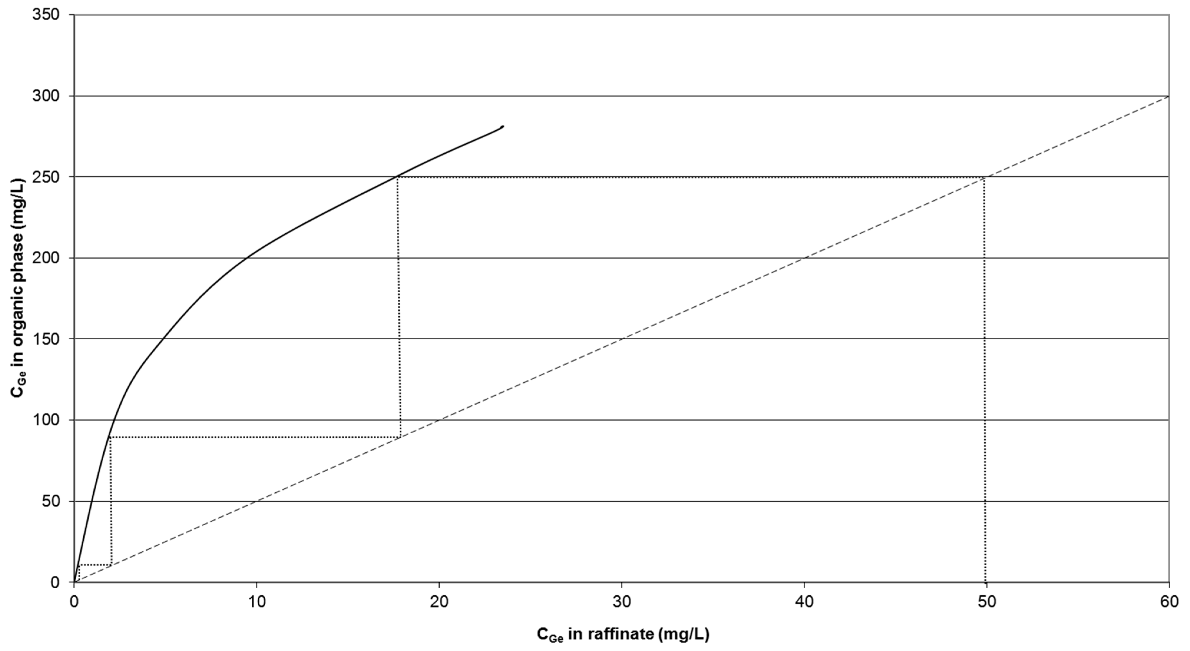
4.3.1. Number of Stages

The number of stages has been determined graphically from the McCabe-Thiele diagram that represents the equilibrium curve and the operating line. The equilibrium curve consists of a series of experimental points, which represents the germanium content in raffinate and the Ge content in the organic extract for different volumetric ratios (AP/OP) and residence times. After contact, both phases are in equilibrium. The operating line sets the operating conditions and its slope is the ratio AP/OP.
The graphical representation of the McCabe-Thiele diagram of this system is shown in Figure 3 [21]. Three theoretical stages are required, and the extraction yield achieved is 98%.
Figure 3. McCabe-Thiele diagram of extraction system.
Minerals 05 00298 g003
According to Cox and Musikas [31], the number of real stages should be the theoretical number multiplied by 1.5–2. So, the real number of extraction stages should be five.

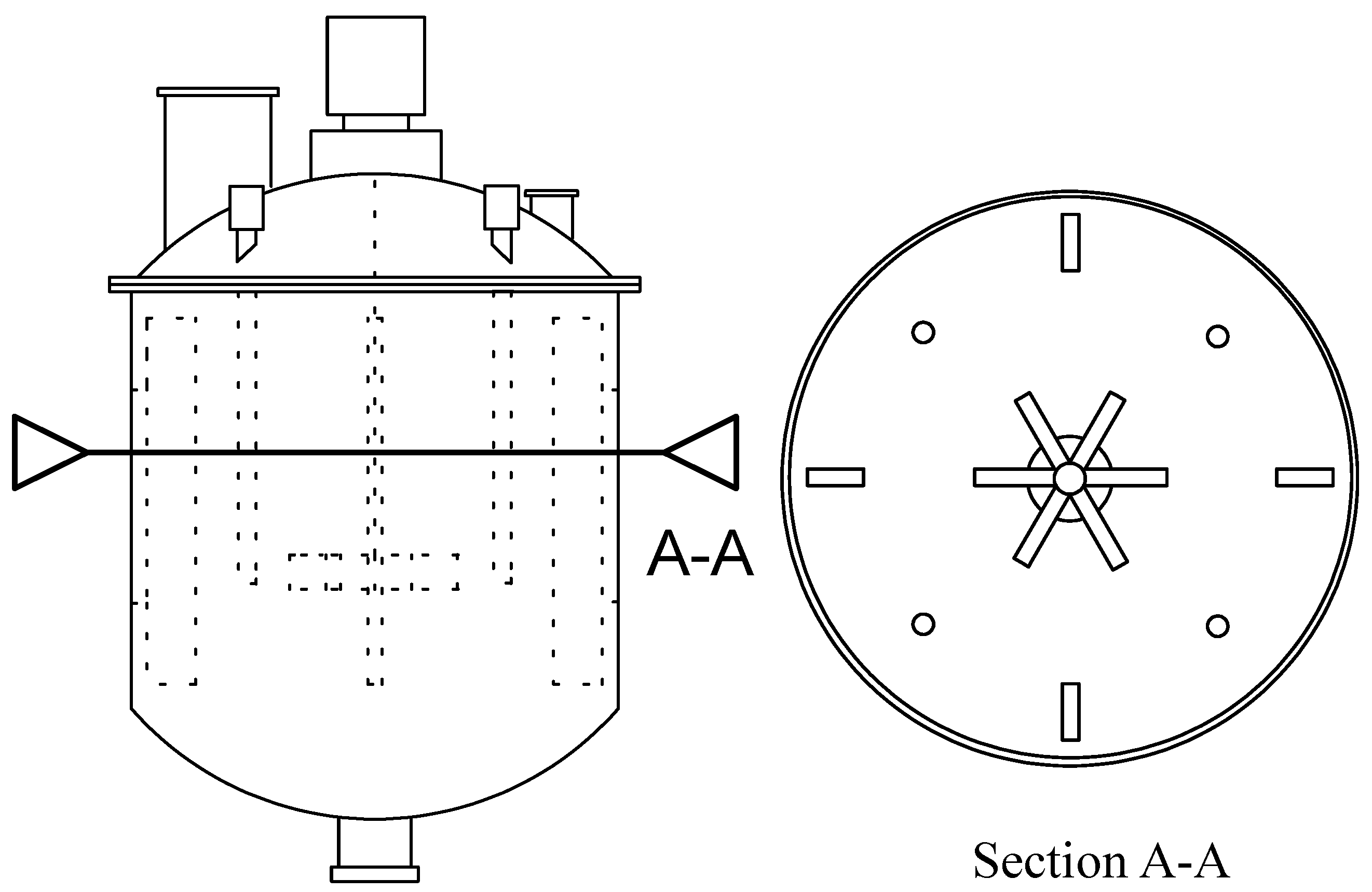
4.3.2. Mixer Geometry

The extraction equipment consists of a mixing chamber, where phases are contacted in counter-current and are mixed by the effect of agitation, and the settler consists of a settling chamber, where the phases are separated. Each extraction stage comprises one mixer and one settler.
The extraction mixer is made up of vertical cylindrical equipment with a tori-spherical bottom head constructed of stainless steel AISI 316, similar to the leaching reactor but with different size. Taking into account the flows of the aqueous and organic phases (Table 2), the residence time (5 min) and the filling factor (80%) according to results obtained in pilot plant tests [21,22], the volume in the mixer is 0.113 m3 (Equation (3)) and the diameter and height of the mixer have both been determined as 480 mm (Equation (4)). Four baffles have been distributed along the perimeter of the tank (cross form): bw = 48 mm, bc = 8 mm and ba = 24 mm (Equations (5)–(7)).
According to previous considerations, the geometry of the turbine agitator was dimp = himp = 160 mm, and lblades = 40 mm (Equations (8)–(10). The Nmax recommended for this agitator was 120 r·min−1 (Equation (11)) and the calculated power is 0.02 kW.

4.3.3. Settler Geometry

The settler is a parallelepiped constructed of stainless steel AISI 316. The most important aspect of this settler is the total separation of the phases, which is difficult since the ratio AP/OP is very large and OP occupies a small fraction of the volume settler. The most important design parameter of the sediment in this regard is the specific flow, which is defined as the flow per horizontal area.
In pilot plant tests, several problems with the original settler design were observed. Settling times around 15 min were needed for a complete phase separation. For typical Q/A ranging 0.06–0.1 m3/m2·min [25], settler lengths from 0.9 to 1.5 m were needed. In Table 4, different widths of settler are shown. A preliminary estimate of settler length is 1500 mm to ensure complete phase separation. The flow to the settler is 0.987 m3/h. It is not recommended to exceed the maximum specific flow, so it will take an operational ratio Q/A of 4.8 m3/m2·h. The minimum height of the settler is 100 mm for easy separation of the phases. Therefore, the settler dimensions are: 1500 mm (length), 1100 mm (height) and 140 mm (width).
Table 4. Different options for settler design: widths, ratio Q/A (m3/m2·h) and settling areas.
Settler Design ParametersOptions
Q/A (m3/m2·h)3.64.04.44.85.25.66.0
A (m2)0.270.250.220.210.190.180.16
W (m)0.180.160.150.140.130.120.11

4.4. Stripping Equipment

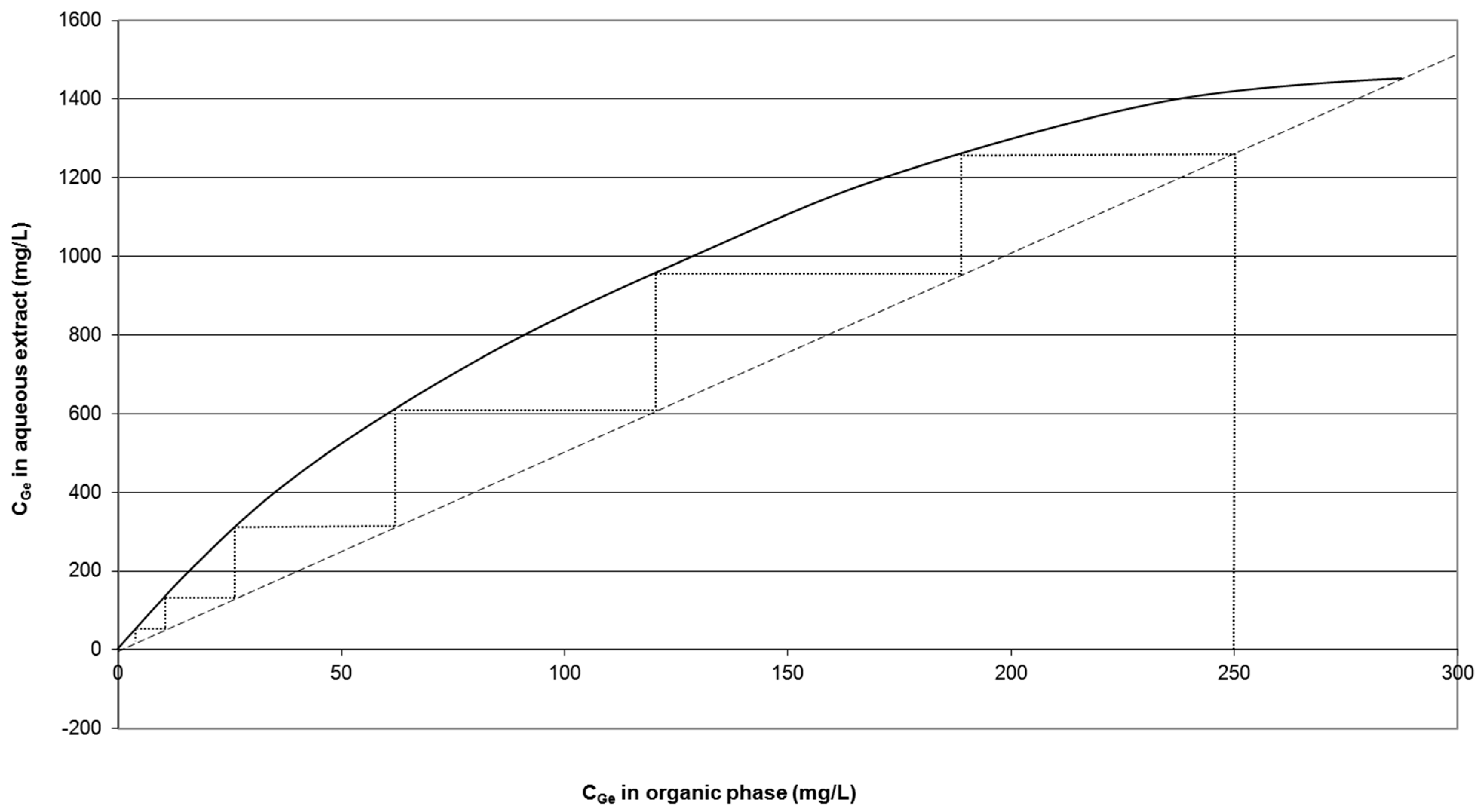
4.4.1. Number of Stages

The graphical representation of the McCabe-Thiele diagram of the stripping system is shown in Figure 4 (data from [21,22]). The theoretical number of required stages is six, and the stripping yield achieved is 96%. According to Cox and Musikas [31], the number of real stages should be the theoretical number multiplied by 1.5–2. Thus, the real number of stripping stages should be nine.
Figure 4. McCabe-Thiele diagram of stripping system.
Minerals 05 00298 g004
The stripping system chosen is the same as for the extraction equipment. The flow arrangement is counter-current.

4.4.2. Mixer Geometry

The SP and OP are in a vertical cylindrical mixer with a tori-spherical bottom constructed of stainless steel AISI 316 (similar to leaching and extraction mixer reactors). For a phase volume ratio of 5 [13,14], the residence time in the stripping mixer (5 min [14]) and the filling factor (80%), the volume of the reactor is 0.023 m3.
According to the equations considered in the design of the extraction mixer (Equations (3)–(11), the stripping mixer is: D = 300 mm and H = 200 mm high with four baffles made of the same stainless steel AISI 316, distributed along the perimeter. A six flat-blade turbine agitator is designed with the following geometry: bw = 30 mm, bc = 5 mm and ba = 15 mm, dimp = 100 mm, himp = 70 mm and lblades = 25 mm. The Nmax allowed for this agitator is 195 r·min−1 and the power consumed by the agitator reaches 0.02 kW.

4.4.3. Settler Geometry

The settler is a parallelepiped constructed of stainless steel AISI 316. In the stripping stage, phases are easily separated [21], so a settling time of around 6 min was enough to ensure phases separation. Taking into account the same considerations as for the extraction settler, for a flow of 0.2 m3/h and Q/A = 3.6 m3/m2·h, the settler dimensions are: 400 mm (length), 280 mm (height) and 78 mm (width).

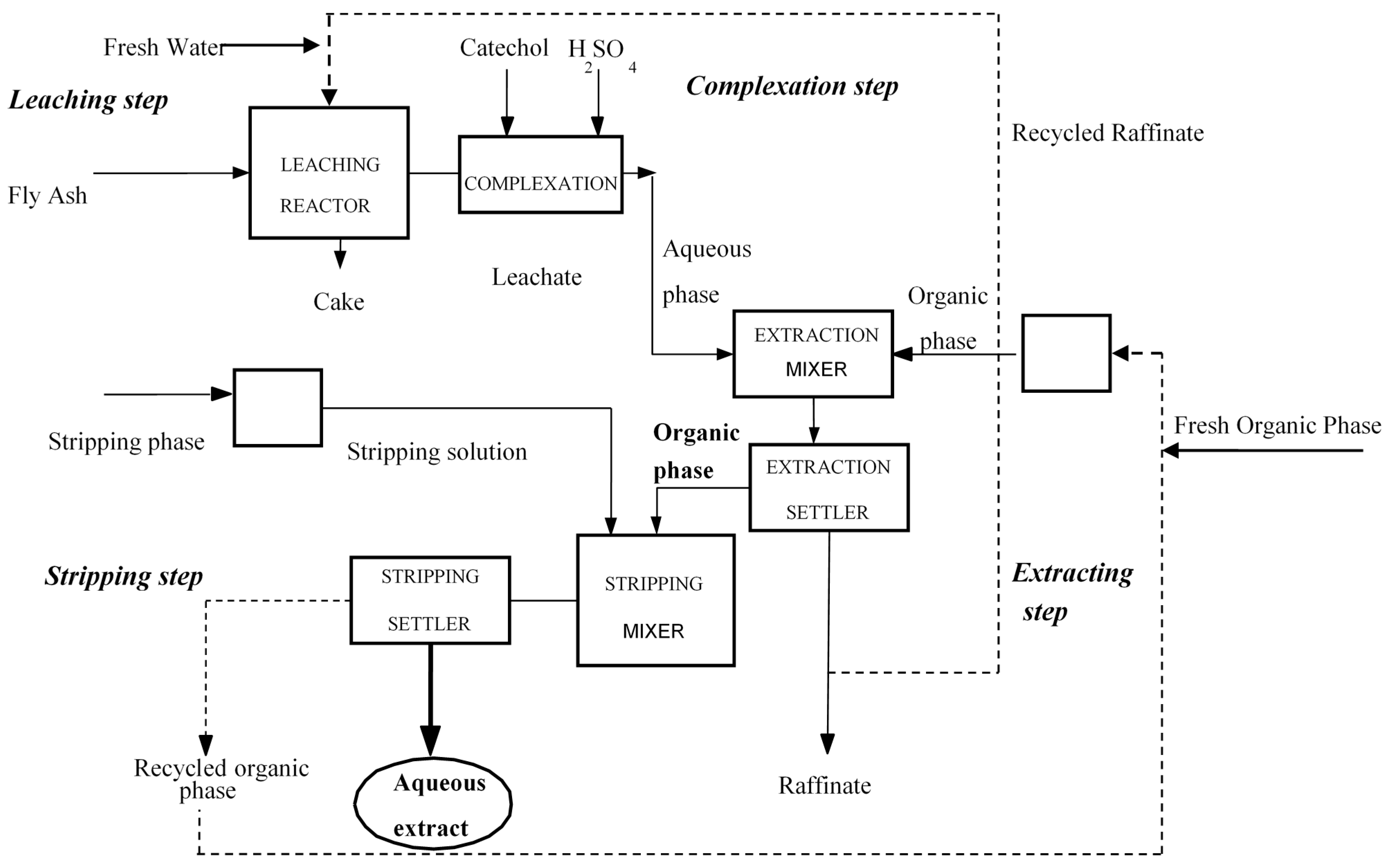
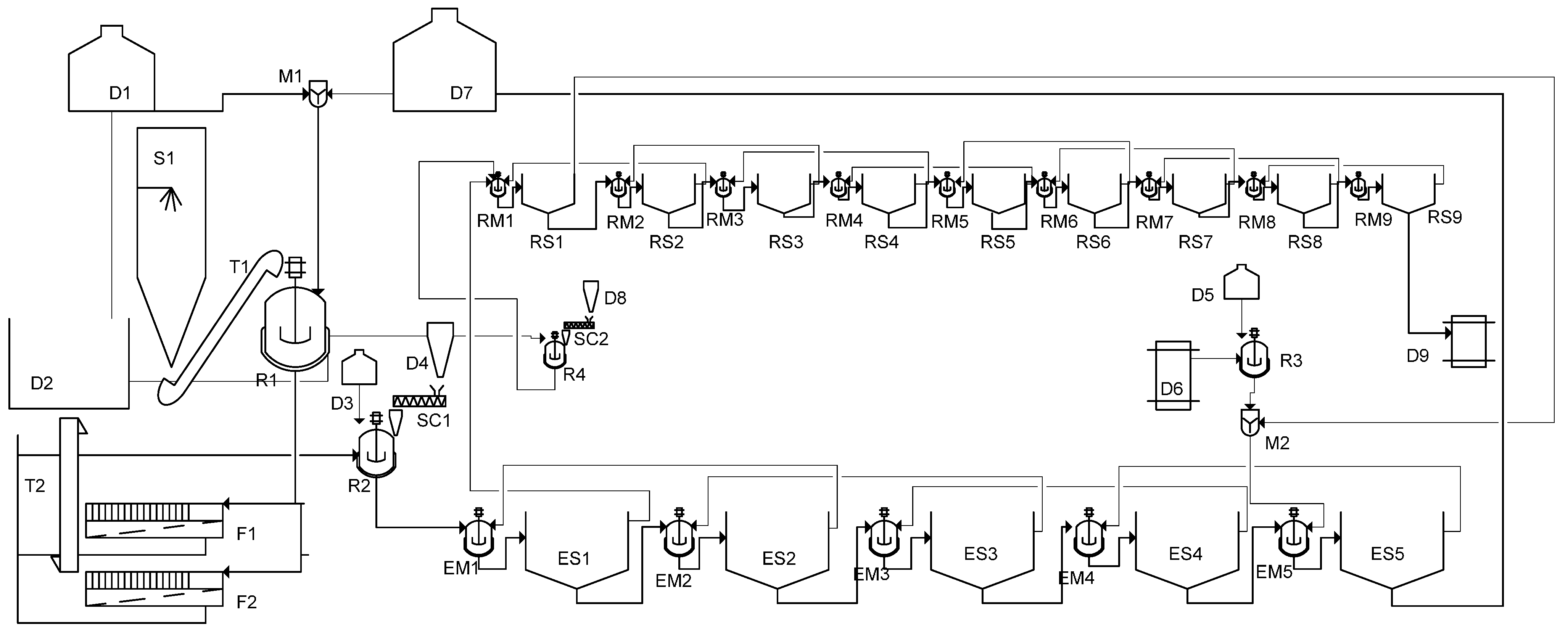
5. Demonstration Plant Scheme

In Figure 5, a basic scheme of the process is shown. Fly ash is stored (S1) from where it is fed into the leaching reactor (R1) through the conveyor T1. The feed flow is 200 kg/h of FA.
Figure 5. Demonstration plant scheme.
Minerals 05 00298 g005
The plant has a water storage tank D1 for a day of plant operation in case of failure. Most of the leaching solution quantity is reintroduced from the process (raffinate from solvent extraction stage).
The slurry from the leaching reactor R1 is pumped to one of the filter press (F1 or F2). Two press filters have been installed so that one can filter while the other is discharged and cleaned. Wet fly ash with 35% moisture (approx.) is stored until reutilization (D2).
Leachate collected from the filter is pumped to the mixer (R2) where extracting solution is prepared by addition of catechol and sulfuric acid. CAT is stored in solid state (D4) and transported to the R2 with a screw (SC1). Sulfuric acid is stored in the tank D3 and pumped to R2. The OP prepared in the reactor R3 consists of kerosene and trioctylamine. Kerosene is stored in D6 and pumped to R3. Similarly, TOA is stored in D5 and pumped to R3.
The AP and OP are introduced in the first and last stages of SX equipment respectively. Each stage is made up of a mixer-settler (ER1-ER5/SR1-SR5).
Raffinate is stored in the tank D7 until its reintroduction in the R1 (leaching stage).
The pregnant OP is introduced in stripping equipment, where it is in contact with sodium hydroxide 3 M coming from R4, which receive sodium hydroxide in solid form from the silo D8 and tank water D1. The stripping equipment is named RE1-RE9/RS1-RS9.
After stripping, the pregnant and concentrated solution of germanium is stored in the tank D9 designed for that purpose. The organic waste is stored in D10 until the returned to the extraction stage.

6. Cost Estimation

This section provides factored cost estimation (Lang methodology) based on the ratio of main plant equipment (mixers and settlers). This estimate has an accuracy of 30%. The Lang methodology for cost estimation consists of two steps:
Step 1: Estimated cost of main equipment. The total cost of main equipment is the sum of the estimated costs of main individual equipment (Table 5).
Table 5. Factors for global investment estimation.
EquipmentCost (€)
Extraction equipment-
Mixers75,000
Settlers25,000
Stripping equipment-
Mixers70,000
Settlers30,000
Auxiliary reactors50,000
Pumps30,000
Liquid store70,000
Total360,000
Step 2: Corrections. The cost calculated in Step 1 has to be corrected to consider additional costs such as direct and indirect costs. This correction factor is called a global factor of Lang and it is a function of the type of plant. The global cost can be calculated as shown in Equation (18) [32].
I TOTAL = ( I b ) ( Σ f dir f Ind f fix ) = F Lang I b
Where Itotal is the total investment, Flang is the Lang factor and Ib is the total cost of main equipment, fdir includes the factors to estimate direct costs and find includes the factors to estimate indirect costs (Table 5).
The estimated investment for the demonstration plant implantation is: 375,000 × 4.8 = 1,800,000 €.

7. Conclusions

The conceptual process design of a demonstration plant has been performed, including the evaluation of process, the identification of equipment options and early investment analysis.
The mass balance of the demonstration plant (200 kg/h) has been performed using the experimental results obtained at pilot plant scale (5 kg/h).
Main equipment (leaching reactor, filters, and extraction and stripping equipment were designed and data for the preliminary design was obtained in tests at laboratory and pilot plant scale.
Almost 61 g/h of GeO2 (equivalent) could be recovered from a 200 kg/h of industrial residue such as fly ash.
The estimated investment for the demonstration plant (direct and indirect costs) is 1,800,000 euros.

Author Contributions

Fátima Arroyo performed some calculations and wrote the paper, Constantino Fernández-Pereira revised the paper, and Pilar Bermejo performed some of the calculations.

Conflicts of Interest

The authors declare no conflict of interest.

References and Notes

  1. Adams, J.H.; Thomas, D. Germanium and germanium compounds. In Ullman’s Encyclopedia of Industrial Chemistry; Wiley-VCH Verlag GmbH: New York, NY, USA, 2000. [Google Scholar]
  2. MetalPrices. Available online: http://www.metalprices.com (accessed on 26 May 2015).
  3. Querol, X.; Fernández-Turiel, J.L.; López-Soler, A. Trace elements in coal and their behaviour during coal combustion in a large power station. Fuel 1995, 74, 331–343. [Google Scholar] [CrossRef]
  4. Font, O.; Querol, X.; Huggins, F.; Chimenos, J.M.; Fernández, A.I.; Burgos, S.; García Peña, F. Speciation of major and selected trace elements in IGCC fly ash. Fuel 2005, 84, 1364–1371. [Google Scholar] [CrossRef]
  5. Font, O.; Querol, X.; Lopez-Soler, A.; Chimenos, J.M.; Fernandez, A.I.; Burgos, S.; Garcia Pena, F. Ge extraction from gasification fly ash. Fuel 2005, 84, 1384–1392. [Google Scholar] [CrossRef]
  6. Font, O.; Querol, X.; Plana, F.; Coca, P.; Burgos, S.; Pena, F.G. Condensing species from flue gas in Puertollano gasification power plant, Spain. Fuel 2006, 85, 2229–2242. [Google Scholar] [CrossRef]
  7. Font, O.; Querol, X.; Juan, R.; Casado, R.; Ruiz, C.R.; López-Soler, A.; Coca, P.; García Peña, F. Recovery of gallium and vanadium from gasification fly ash. J. Hazard. Mater. 2007, 139, 413–423. [Google Scholar] [CrossRef] [PubMed]
  8. Font, O. Trace Elements in Integrated Gasification Combiner Fly Ash: Extraction of Potential Valuable Elements. Ph.D. Thesis, Universitat Politècnica de Catalunya, Barcelona, Spain, 2007. [Google Scholar]
  9. Jandova, J.; Vu, H. Recovery of Germanium-Bearing Fly Ash. In Metallurgy, Refractories and Environment; Technical University of Košice: Košice, Slovakia, 2001; pp. 107–112. [Google Scholar]
  10. Matis, K.A.; Mavros, P. Recovery of Metals by Ion Flotation from Dilute Aqueous Solutions. Sep. Purif. Rev. 1991, 20, 1–48. [Google Scholar] [CrossRef]
  11. Hernández-Expósito, A.; Chimenos, J.M.; Fernández, A.I.; Font, O.; Querol, X.; Coca, P.; García Peña, F. Ion flotation of germanium from fly ash aqueous leachates. Chem. Eng. J. 2006, 118, 69–75. [Google Scholar] [CrossRef]
  12. Marco-Lozar, J.P.; Cazorla-Amorós, D.; Linares-Solano, A. A new strategy for germanium adsorption on activated carbon by complex formation. Carbon 2007, 45, 2519–2528. [Google Scholar] [CrossRef]
  13. Arroyo, F.; Fernández-Pereira, C.; Querol, X.; Font, O.; Coca, P.; Chimenos, J.M.; Fernández, A.I. Method for the Recovery of Germanium Present in Coal Ash. Patent WO/2008/003808, 10 January 2008. [Google Scholar]
  14. Arroyo, F.; Fernandez-Pereira, C. Hydrometallurgical recovery of germanium from coal gasification fly ash, solvent extraction method. Ind. Eng. Chem. Res. 2008, 47, 3186–3191. [Google Scholar] [CrossRef]
  15. Menendez, F.J.S.; Menendez, F.M.S.; de La Cuadra Herrera, A.; Tamargo, F.A.; Valcárcel, M.R.; Fernandez, V.A. Process for the Recovery of Germanium from Solutions that Contain It. US Patent 4,886,648, 29 June 1989. [Google Scholar]
  16. Harada, A.; Tarutani, T.; Yoshimura, K. Spectrophotometric determination of germanium in rocks after selective adsorption on Sephadex gel. Anal. Chim. Acta 1998, 209, 333–336. [Google Scholar] [CrossRef]
  17. Arroyo Torralvo, F.; Fernández-Pereira, C. Recovery of germanium form fly ash leachate by ion-exchange extraction. Miner. Eng. 2011, 24, 35–41. [Google Scholar] [CrossRef]
  18. Moskalyk, R.R. Review of germanium processing worldwide. Miner. Eng. 2004, 17, 393–402. [Google Scholar] [CrossRef]
  19. Arroyo Torralvo, F.; Font, O.; Pereira Fernandez, C.; Querol, X.; Juan, R. Germanium recovery from gasification fly ash: Evaluation of end-products. J. Hazard. Mater. 2009, 167, 582–588. [Google Scholar] [CrossRef] [PubMed]
  20. Arroyo Torralvo, F.; Fernandez-Pereira, C.; Coca, P. Precipitación of germanium from coal fly ash leachates. Coal Combust. Gasif. Prod. 2010, 2, 28–34. [Google Scholar]
  21. Arroyo Torralvo, F. Recuperación del Germanio Presente en la Ceniza Volante Producida en Una Planta GICC que Emplea Carbones de la Cuenca de Encasur en Puertollano. Ph.D. Thesis, University of Seville, Seville, Spain, 2008. [Google Scholar]
  22. Arroyo, F.; Fernández-Pereira, C.; Olivares, J.; Coca, P. Hydrometallurgical Recovery of Germanium from Coal Gasification Fly Ash: Pilot Plant Scale Evaluation. Ind. Eng. Chem. Res. 2009, 48, 3573–3579. [Google Scholar] [CrossRef]
  23. Palluzi, R.P. Pilot plants. In Ullman’s Encyclopedia of Industrial Chemistry; Wiley-VCH Verlag GmbH: New York, NY, USA, 2005. [Google Scholar]
  24. Crittenden, J.C.; Trussell, R.; Hand, D.W.; Howe, K.J.; Tchobanoglous, G. Principles of Reactor Analysis and Mixing. In MWH’s Water Treatment: Principles and Design, 3rd ed.; John Wiley & Sons: Hoboken, NJ, USA.
  25. Perry, R.H.; Green, D.W. Perry’s Chemical Engineers’ Handbook, 7th ed.; McGraw-Hill: New York, NY, USA, 1997. [Google Scholar]
  26. Thakur, R.K.; Vial, C.; Djelveh, G.; Labbafi, M. Mixing of complex fluids with flat-bladed impellers: Effect of impeller geometry and highly shear-thinning behavior. Chem. Eng. Process. 2004, 43, 1211–1222. [Google Scholar] [CrossRef]
  27. Wei, J.; Anderson, J.L.; Bischoff, K.B. Advances in Chemical Engineering; Academic Press: Waltham, MA, USA, 1991; Volume 17. [Google Scholar]
  28. Al-Khafaji, A.A.A.R. Prediction of Filter Life by Measurement of Cake Resistance. Ph.D. Thesis, Iowa State University, Ames, IA, USA, 1967. [Google Scholar]
  29. Sincero, A.P.; Sincero, G.A. Environmental Engineering. A Design Approach; Prentice Hall: Upper Saddle River, NJ, USA, 1996. [Google Scholar]
  30. Stevens, G.W.; The, C.L.; Malcolm, H.B. Extraction, Liquid-Liquid. In Kirk-Othmer Encyclopedia of Chemical Technology; John Wiley and Sons: Hoboken, NJ, USA, 2007. [Google Scholar]
  31. Cox, M.; Musikas, C. Solvent Extraction Principles and Practice; CRC Press: Boca Raton, FL, USA, 2004. [Google Scholar]
  32. Plant Design and Economics for Chemical Engineers. Max S. Peters, University of Colorado, Klaus Timmerhaus, University of Colorado, Boulder, Ronald E. West, University of Colorado, Boulder. Available online: http://highered.mheducation.com/sites/0072392665/student_view0/index.html (accessed on 22 May 2015).

