
Study on Magnetite Ore Crushing Assisted by Microwave Irradiation


Beijing Key Laboratory of Urban Underground Space Engineering, University of Science and Technology Beijing, Beijing 100083, China
*
Authors to whom correspondence should be addressed.
Minerals 2021, 11(10), 1127; https://doi.org/10.3390/min11101127
Submission received: 10 September 2021
/
Revised: 7 October 2021
/
Accepted: 10 October 2021
/
Published: 14 October 2021
(This article belongs to the Section Mineral Processing and Extractive Metallurgy)
Abstract
:High energy consumption in ore crushing brings great challenges to the mining industry. Microwave irradiation provides a promising solution for rock breaking. However, there is currently a lack of detailed understanding of the microwave parameters regarding magnetite ore. The purpose of this study is to fully understand the potential value of microwave irradiation applied in auxiliary crushing of magnetite ore. It is typically found that increasing power reduces the mechanical properties of ore, increasing energy utilization, and crushing degree, more than extending time. Based on wave impedance, this reveals the dependence of energy utilization on thermal damage. Increasing irradiation power, time and cooling rate will cause more transgranular cracks and cleavage tears in the crushed ore. Based on the separate microwave response of several minerals, the microwave-damage mechanism of magnetite ore is further demonstrated.
1. Introduction
Ore is an important material for global economic development. In the mining and mineral processing industries, ore will undergo enrichment processes such as stope blasting, coarse crushing, and fine crushing. Reducing the size of the large pieces of ore is an energy-intensive process, accompanied by huge energy consumption. Taking several mining countries as examples, in Canada’s national industrial energy consumption, the mining industry accounts for approximately 16.7% [1,2]. In Australia, the energy consumption of the mining industry can reach 1.48% of the total national energy consumption [3]. Mining operation can account for 6% of South Africa’s total energy consumption, and ore crushing alone accounts for 1.8% of the total energy consumption [4].
Ore crushing is an important process in its utilization. According to the statistics of the U.S. department of energy, in the total energy consumption of mining in the United States, the energy consumption for ore crushing is about 30% [5,6]. The ore crushing operation can account for 3–4% of global electricity generation, but its energy utilization efficiency is less than 1% [7,8,9]. However, it is worth noting that in the utilization process of ore resources, there is not only huge energy consumption, but also serious wear of the crushing equipment, leading to the cost of maintaining equipment occupying approximately 30–50% of the total cost of mining [10].
Under an increasingly tight global energy supply and the demand of sustainable development, it is very important to improve the energy utilization efficiency of ore crushing. At present, breaking rocks with lower uniaxial compressive strength (UCS) can be achieved by improving the crushing process. To make rock breaking with high UCS more economical, a new technology is needed to assist the ore crushing [11]. Nowadays, the microwave heating technology used in materials processing and soil remediation has the characteristics of fast heating rate, uniform heating, and high efficiency [12,13]. It is a potential new technology to assist rock breaking. Many scholars have done research on the response of rocks to microwave irradiation, which is mainly manifested in the following two aspects.
Firstly, in the physical mechanism of rock thermal damage. Li et al. [14] used COMSOL software to analyze the change of mises stress and first principal stress, indicating that chlorite is the most sensitive to temperature, leading to the most serious thermal damage between minerals. According to the changes in the thermodynamic parameters (specific heat capacity, thermal diffusivity, and thermal expansion) of basalt, granite, and sandstone, Hartlieb et al. [15] found that due to the different content of quartz in these rocks, their microwave responses are very different. It is further found that under the same microwave irradiation, the microwave absorption capacity of rock is closely related to mineral composition and water content [16]. Under microwave irradiation, some researchers found that the surface temperature of the rock is lower than the internal temperature (internal “overheating” phenomenon). To explore the mechanism of this phenomenon inside the rock, based on the “3D melting and propagation of rock” reported in [17], Zeng et al. [18] pointed out that the feldspar inside granite is melted first, and subsequent magmas and cracks accelerate the collapse and disintegration of the rock.
Secondly, in terms of microwave-assisted rock fracture. Whittles et al. studied the expansion behavior of calcite-containing iron-sulfide particles and found that microwave irradiation could effectively reduce the UCS [19]. According to the numerical simulation, calcite presents radial fractures under microwave irradiation, and the thermal damage of the rock can be aggravated more by pulse microwave than continuous microwave [20]. For dark minerals, the thermal cracks caused by microwave irradiation are not easily observed. Therefore, Zheng et al. [21] used fluorescent resin to clearly show the propagation paths of radial cracks. To promote microwave irradiation technology to practical engineering, Shepel et al. [22] designed experiments for cutting and tunneling granite and obtained the regression relationship between driving force and microwave parameters. It was pointed out that only when the irradiation time exceeded a certain threshold, would the weakening of rock strength be obvious. Nicco et al. [23] revealed the influence of microwave irradiation on rock fracture by using P-wave velocity, UCS, and micro-crack distribution. Lu et al. [24,25] found that the greater the power and irradiation time, the smaller the P-wave velocity and UCS of basalt. Due to the different dielectric constants of minerals, thermal stress with non-uniform distribution is generated under microwave irradiation, which causes thermal fracture and weakens the ability of resisting external load. In summary, microwave irradiation can improve the production efficiency of hard rock excavation, drilling, and breaking [26,27].
In the exploitation of mineral resources, the geological materials are mainly the surrounding rock with the largest reserves and ore used in mining industry. In published works, researchers mainly analyzed the failure behavior of surrounding rock (granite, basalt, marble, sandstone, etc.) under microwave irradiation. However, the effect of microwave irradiation on ore mainly focuses on the recovery of metal elements, separation of minerals, and removal of impurities [28,29,30]. The types of minerals in ore are obviously different from the surrounding rock. The study on auxiliary ore crushing by microwave irradiation (mechanical strength, absorbed energy, and particle size) is of great significance for the mining industry to reduce energy consumption. However, to the author’s knowledge, there are very few research reports on this aspect.
The aim of this study is to explore the priority order of microwave parameters affecting the mechanical properties, absorbed energy, and particle size distribution, and reveal the influence of microwave irradiation, on the microscopic fracture of ore. Magnetite ore was used as the test material, and the ore specimens were treated with microwave irradiation of different heating paths and cooling paths in advance, before subjecting these specimens to impact crushing. The microwave response of several minerals inside the ore was analyzed separately from the mineral composition and microscopic fracture.
2. Materials and Methods
2.1. Experimental Principle
The size of the ore produced by blasting is not uniform and there will be many large pieces. Mining workers mainly use impact crushers and hammer crushers to break large pieces of ore into small pieces. The basic principle of impact crushing and hammer crushing is to break the ore through mechanical impact, which is similar to the drop hammer impact-testing machine. Therefore, the impact crushing tests of ore were carried out by using the drop hammer impact-testing machine (Type: DP-1200, King Design Instrument Technology Co., Ltd, Kunshan, China) in the study. The machine is mainly composed of impact platform, controller, data recorder, guide rod, and prevent re-impact device (PRI) (Figure 1a). The PRI can keep the hammer in contact with the ore and prevent the hammer bounce. The signal transmission wire can transmit data such as load and displacement to the data recorder. The mechanical impact between hammer and ore is shown in Figure 1b.
The hammer freely falls from a certain height to collide with the ore, and the upper end of the ore is subjected to mechanical collision to form the stress wave. The total energy carried by the stress wave is transformed into absorbed energy , kinetic energy , and transmitted energy , which could be obtained directly in the data recorder. There is the following relationship between several kinds of energy [31].
where is the hammer mass (kg), is the impact height (m), and is the gravitational acceleration.
2.2. Experimental Methods
The microwave irradiation system is mainly composed of microwave generator, microwave guide device, heating cavity, and cooling device. Microwave energy is generated by the magnetron in the microwave generator and transmitted to the heating cavity through the guide device that reflects all microwaves. Both single-mode cavity and multi-mode cavity can be used to heat materials, but the heating of the multi-mode cavity is more uniform and the power density is 10–15 times that of single-mode cavity [32]. In this study, an industrial microwave system with multi-mode cavity (Type: RWLM6, Zhongsheng Thermal Energy Technology Co., Ltd, Yueyang, China) was selected (Figure 1c). The microwave output power of the device is 0–6.5 kW, the maximum heating temperature is 1650 ℃, the microwave frequency is 2.45 GHz, and the size of multi-mode cavity is 150 mm × 150 mm.
The specimens in this study come from the same magnetite parent rock with no obvious joints and defects in the Shuichang iron mine (Anshan-type sedimentary metamorphic rock, Qian’an, China). The average UCS of this ore is 168.80 MPa. According to the requirements of the International Society for Rock Mechanics [33], the magnetite ore was preformed into several cuboid specimens with the size of 50 mm × 50 mm × 100 mm, and the non-parallelism of the upper and lower ends of the specimens do not exceed 0.05 mm. The ultrasonic velocimetry was used to obtain the longitudinal wave velocity of the specimens. Some specimens with similar parameters (density and wave velocity) were selected for microwave irradiation test. Table 1 shows the physical parameters of all specimens in this study.
The higher the microwave power or the longer the irradiation time, the more serious the damage will be. However, in practical production, the power of microwave irradiation should not be too large, otherwise it will increase electricity consumption. Similarly, the irradiation time should not be too long, otherwise it will affect the production efficiency of the subsequent ore crushing. When determining the microwave irradiation parameters, we found that when the power is lower than 0.8 kW through pilot experiments, it is difficult to generate thermal cracks on the ore surface. Despite being irradiated at 0.8 kW for 15 min, the thermal cracks are also not obvious. Therefore, to explore the priority order of the influence of microwave parameters on ore thermal damage, two groups of tests (WP and WT) were set up. In the group WP, the power used was 2.0 kW, and the irradiation times were 3 min, 5 min, and 7 min. In the group WT, the irradiation time was 5 min, and the power used were 1.2 kW, 2.0 kW, and 2.8 kW. Considering that the cooling rate will affect the damage of ore, the group CP was added to carry out cooling treatment in different paths. Table 1 shows the detailed parameters of each test.
When impact crushers and hammer crushers crush ore, the rotation speed of the center rotor (which determines the impact speed of the hammer) is related to the size of the material. Meanwhile, there are many types of the two devices in actual crushing. For different types of crushers, the impact speed of the hammer is different. Generally speaking, when the material is coarsely crushed, the impact speed of the crusher hammer is generally not more than 30 m/s. In this study, the hammer with a mass of 10 kg and an impact velocity of 10 m/s in the crusher was taken as an example. The kinetic energy of the hammer is about 500 J. Limited by the test equipment, the impact speed of the hammer in this test should not be too large. Therefore, a hammer with a mass of 50 kg was selected for the impact test with an impact height of 1000 mm in this study. At this time, the kinetic energy of the hammer in this test is not much different from that of the hammer in the crusher. After the microwave irradiation and cooling tests, the specimens were placed on the impact platform to make it align with the axis of the hammer, and the impact tests were carried out under the same conditions (= 50 kg, = 1000 mm). The fragments were sieved using standard gravel sieve with apertures of 0.075 mm, 0.1 mm, 0.25 mm, 0.5 mm, 1 mm, 2 mm, 5 mm, 10 mm, and 20 mm. The fragments at the upper end of the specimens were collected, and gold film was sprayed on the fracture section by the vacuum coating instrument (Figure 1d). The microscopic morphology of sections was obtained by scanning electron microscope (Type: JSM-7900F, JEOL Ltd, Tokyo, Japan) (Figure 1e).
3. Results
3.1. Changes of Dynamic Strength
The strength characteristic of the ore under impact load is directly related to the damage state, and it is an important parameter to evaluate the wear degree of crushers. Figure 2 shows the influence of heating paths and cooling paths on the ore dynamic strength. In the groups WT and WP, increasing the power or extending the time can significantly weaken the dynamic strength. Although the heating rate of each mineral is different, due to the small size of the minerals, heat conduction can compensate for the difference in the heating rate and keep the temperature of adjacent minerals the same. Therefore, the difference of dielectric constant is not considered to be the direct cause of thermal cracks. Generally speaking (without considering the minerals melting), thermal cracks are generated between the minerals due to thermal expansion. The thermal fracture between adjacent minerals can be represented by the following mechanical model.
where is the thermal stress between minerals, is the temperature increment (K), and are the thermal expansion coefficients of minerals, and and are the elastic modulus of minerals (MPa). Increasing power will increase in unit time, resulting in an increase of between adjacent minerals. Thermal cracks will occur when exceeds the ultimate strength. The higher the power, the greater the thermal stress and deformation between adjacent minerals, and the more thermal cracks, the more significant will be the weakening of ore dynamic strength. In groups WP and WT, when the microwave total energy (power × time) is the same, it is not difficult to find that the dynamic strength of ore treated with higher power is lower than that treated with lower power. It can be seen that among the factors that weaken the mechanical properties of ore, increasing the power takes priority over extending the time.
In group CP, the mechanical properties of ore are closely related to the cooling path. When using water impact, the ore at a high-temperature state conducts heat with the water, and the ore quickly releases heat to the outside world. On the one hand, the greater the ore cooling rate, the more obvious the shrinkage deformation and non-uniform tensile stress between minerals, and the more significant the thermal shock. On the other hand, the liquid water will be vaporized after entering the ore, increasing internal pressure and promoting the expansion and connection of thermal cracks. In industrial production, after microwave irradiation, increasing the cooling rate can reduce the wear of crushers.
3.2. Changes of the Absorbed Energy
The macroscopic breaking of ore is accompanied by irreversible energy dissipation. How one improves the utilization of mechanical energy directly affects the energy consumption of industrial crushing. Figure 3 shows the influence of heating paths and cooling paths on the absorbed energy and energy utilization of ore. Under the same mechanical energy, increasing the power, time, and cooling rate can increase the thermal damage and improve the absorbed energy and energy utilization efficiency. Similar to the change of dynamic strength, when the microwave total energy (power × time) is the same, the absorbed energy of ore treated with higher power is higher than that of the ore treated with lower power. This indicates that ore with high thermal damage more easily absorbs mechanical energy than ore with low thermal damage. The mechanisms are as follows.
When the hammer touches the ore, the stress wave will be formed at the “hammer-ore” interface. Because the PRI device keeps the hammer in contact with the ore all the time, the reflected waves formed in the hammer will continue to propagate into the ore. As shown in Figure 4, taking the stress wave propagation at the interface of “ore-platform” as an example ( is the density, is the wave velocity). Let the wave impedance of the ore be , the wave impedance of the platform be , the particle stress caused by the incident wave be , the particle stress caused by reflected wave be , and the particle stress caused by transmitted wave be . According to the principle of superposition and the consistency of the particle states on the two interfaces, there are the following [34].
Further,
where and are the reflection coefficient and transmission coefficient at the interface of “ore-platform” respectively. Let be the intermediate parameter, then and have the following form.
It is well known that increasing the thermal damage will decrease the density and wave velocity of the ore. At the “ore-platform” interface, the wave impedance of the platform (high strength steel, >) is constant. The more serious the thermal damage and the lower the wave impedance of the ore, the smaller the and the larger the of the ore, which makes the increase. Ore with lower wave impedance will suffer more intense reflection stress and more energy will be used for ore crushing. In other words, the energy utilization efficiency is dependent on the thermal damage degree of ore. In this study, the absorbed energy increases due to the decrease of wave impedance. This is similar to how the transmitted energy ratio of coal (low wave impedance) is lower than that of hard rock (high wave impedance) in the Split Hopkinson Pressure Bar (SHPB) test (more energy is absorbed by the material with low wave impedance) [35,36].
3.3. Changes of Crushing Degree
The average fragmentation is a key indicator that affects the energy consumption of ore crushing [37]. is used to represent the size distribution of fragments.
where is the aperture, and is the mass percentage of the fragments corresponding to the aperture . The rock failure is the result of the development, coalescence, and convergence of cracks, and the fracture process of rock has a fractal nature [38,39]. The macro-fracture of magnetite ore is caused by small fracture clusters, which are formed by the evolution of micro-cracks. The self-similarity of micro-fracture leads to the self-similarity of macro-fracture. The fractal dimension can be used to characterize the crushing degree of ore, and its calculation method is as follows.
where is the size of fragments, is the maximum size of fragments, is the mass of fragments, is the maximum mass of fragments, and is the number of fragments with the maximum size or mass.
Since it is difficult to accurately estimate the number of fragments, the G–G–S distribution based on the “mass-frequency” method was chosen to characterize the fragments distribution of ore [40].
where is the mass of fragments with an aperture less than , is the total mass of fragments, and is the intermediate parameter. can be calculated by the double logarithmic axis.
Figure 5 shows the influence of heating paths and cooling paths on and . Similar to dynamic strength and absorbed energy, increasing irradiation power is still prioritized over extending time among the microwave parameters affecting the crushing degree. Increasing the power, time, and cooling rate enables the ore to absorb more impact energy, and microcracks that release elastic strain energy increase, forming a more complex cracks network, which leads to the increase of fine debris and the reduction of large debris.
3.4. Micro-Mechanism of Microwave-Assisted Ore Crushing
3.4.1. Microscopic Explanation of the Change of Crushing Degree
Under the same impact load, specimens with different heating paths or cooling paths show different fracture characteristics. Analyzing the microstructures of minerals can effectively reveal differences in their fracture. Figure 6 shows the two main micro-morphologies of ore (to make the images clearly, ImageJ software (Version: 1.8.0, National Institutes of Health, Bethesda, USA) was used to conduct false color processing on the SEM images). Shear stress drives the two walls of thermal cracks to slip, and it is easy to form the smooth flat morphology as shown in Figure 6a. Under tensile stress, the micro-section will form a relatively rough morphology (Figure 6b). When the microwave energy is high, it is easy to form micro-pits with ductile fractures (Figure 6b).
Figure 7 shows the morphology of ore in group WP. According to the influence of microwave irradiation on the rock microstructure [41,42], when the irradiation time is short, more intergranular (I) cracks and some transgranular (T) cracks are generated (Figure 7a). There is a relative slip between the two walls of cracks, accompanied by the peeling of a few of the minerals. With the increase of irradiation time, more T-cracks appear on the morphology. Small regional fractures are prone to occur when cracks bifurcate and bend (Figure 7b). When the irradiation time is 7 min, there are many T-cracks and lamellar tear areas (Figure 7c). Figure 8 shows the morphology of the ore in group WT. When the microwave power is low (Figure 8a), step-like and shell-like morphologies are formed by tensile stress, and the type of cracks are mainly I-cracks. With an increase of power, cleavage tear and T-cracks gradually begin to appear (Figure 8b).
Cooling rate has a great influence on the ore. The micro-morphology of ore after water spray and water impact is similar, only the water spray cooling is used as an example to show (Figure 9). Compared with the ore cooled at room temperature (Figure 7b), the ore cooled by water spray not only has more T-cracks, but also has micro-pits with ductile failure. During the propagation of the primary T-cracks, more secondary T-cracks will be generated.
In summary, after the ore is subjected to lower power or time (Figure 7a and Figure 8a), the ore will counteract the mismatch between the active stress (the external load causes the cracks to grow) and the passive stress (friction between two walls of cracks) with more I-fractures [43], resulting in the larger and the smaller after crushing. On the contrary (Figure 7c, Figure 8b), the ore will fracture with the mixed type of I-cracks and T-cracks to hedge the non-equivalence between the two stresses [43]. A large number of cracks make the smaller and the larger, and the crushing degree of ore will be aggravated.
3.4.2. Microscopic Explanation of the Change of Absorbed Energy
The macro-fracture of magnetite ore is closely related to the micro-fracture, and the absorbed energy is affected by the micro-fracture mode. Generally speaking, the energy consumption of multiple fracture modes has the following order [44]. I-fracture (low energy consumption) ≤ T-fracture (medium energy consumption) ≤ cleavage tear (high energy consumption) ≤ ductile failure (higher energy consumption). Figure 7, Figure 8 and Figure 9, and Table 2 summarize the fracture information of ore.
When the power is constant, the lamellar tear occurs with the increase of irradiation time. From the brittle fracture with more I-fractures and less T-fractures, to the ductile fracture with both T-fractures and lamellar tear, the energy consumption will increase. When the irradiation time is constant, the cleavage tear will occur with the increase of the power, and the energy consumption will increase. With the increase of cooling rate (from room temperature to water spray), the micro-pits with ductile failure appear and the energy consumption will also increase. To sum up, the transformation of failure mode from brittleness to toughness indicates the increase of the absorbed energy.
3.5. Separate Responses of Minerals to Microwave Irradiation
Under the influence of electromagnetic oscillation, the polar molecules in the material will undergo ultra-high frequency polar motion. On the one hand, the motion between polar molecules generates a large amount of internal friction heat [45]. On the other hand, the intense movement of molecules in the electromagnetic field corresponds to the increase of the internal energy. Both of these mechanisms can increase the temperature of material. The energy density , which represents the ability to absorb microwaves, has the following form.
where is the dielectric constant in vacuum, is the dielectric loss factor, is the electric field intensity, and is the microwave frequency.
The different of adjacent minerals will lead to different heating rates, which will generate a concentration of thermal stresses and weaken the cementing ability. The thermal damage of ore has a great relationship with the capacity to absorb microwaves. To study the effect of microwave irradiation on ore, it is necessary to analyze the response of each mineral separately. This has been rarely discussed in previous studies, which focused on the effect of microwave on the whole (the overall microwave response of multiple minerals). The main minerals of magnetite ore in this study are calcite (CAL), hornblende (HOR), olivine (OLI), magnetite (MAG), plagioclase (PLA), potassium feldspar (POT), pyroxene (PYR), and quartz (QUA). The authors obtained high purity samples of these minerals through several field geological surveys, trying to comprehensively understand the separate response of minerals to microwave from the XRD (Type: Ultima IV, Rigaku Corporation, Japan) and microscopic morphology. The basic research methods are as follows: the powder samples of each mineral were first obtained by grinder, and the powder samples divided into two parts. One was analyzed by XRD after microwave irradiation (2 kW + 5 min), and the other was directly analyzed by XRD. In addition, the detritus of each mineral was obtained, and part of the detritus was analyzed by SEM (Type: JSM-7900F, JEOL Ltd, Tokyo, Japan) after microwave irradiation (2 kW + 5 min), and the other part was directly analyzed by SEM.
Figure 10 shows the XRD results of several minerals before and after microwave treatment (for calcite, “CAL” means without microwave treatment, and “CAL-M” means after microwave treatment). Before and after microwave irradiation, the diffraction changes of the main components of HOR, OLI, and POT are very small. On the contrary, the diffraction intensity of quartz (group QUA), magnetite (group MAG), calcite (group CAL), and calcium feldspar (group PLA) will be significantly weakened. The position of the maximum peak intensity in group PYR was shifted. According to the XRD theory, the integral of intensity in the diffraction peak is proportional to the volume of a certain phase within the X-ray irradiation range. The greater the intensity of the diffraction peak, the stronger the crystallinity and the larger the crystal grains size. According to Figure 10, under microwave irradiation, the crystallinity of quartz (group QUA), calcite (group CAL), and calcium feldspar (group PLA) were weakened. The change of pyroxene cell parameters will shift the position of the maximum peak intensity in the group PYR. The Fe in the mixed valence (+3 and +2) of magnetite is oxidized to +3 valence at high temperature, which reduces the relative content and the diffraction peak intensity of magnetite.
Figure 11 shows the difference in the microscopic morphology of these minerals before and after microwave treatment. After microwave irradiation, many thermal cracks appear on the morphology of calcite, magnetite, plagioclase, and quartz (calcite even disintegrated). These microcracks make the size and crystallinity of crystal grains decrease, and the intensity of diffraction peak decrease. After irradiation, the microstructure of pyroxene is widely fractured. Many crystal grains with small size are separated from the parent body, which may change the cell parameters of the surface pyroxene and shift the diffraction angle of the maximum peak intensity (Figure 10). Before and after microwave irradiation, changes in the microcrack distribution of hornblende, olivine, and potassium feldspar are not obvious, which is basically the same as the change of XRD (Figure 10).
The dielectric loss factor of minerals is the product of and [46]. ( is the dielectric constant, and is the dissipation factor). Due to the differences of primary geological mineralization in different areas, researchers have some deviations in the determination of . However, on the whole, the dielectric constant of several minerals in this study (except magnetite) is basically less than ten, and the of magnetite is in the range of 33.7–81.0. For minerals containing approximately one component (it is considered that there is no boundary stress concentration due to the different thermal expansion), of hornblende is generally 7.0–8.5, of potassium feldspar is generally 5.0—6.2, of quartz is approximately 5.0, and of calcite is generally 5–10 [46,47,48]. According to the different thermal responses of several minerals under the same microwave (Figure 10, Figure 11), it can be inferred that the reason for the fracture behavior of minerals is not only related to their dielectric properties, but also to their thermophysical properties (specific heat capacity, thermal expansion coefficient, thermal diffusivity) [15], mechanical properties (tensile strength, Young’s modulus), and residual stress between minerals.
The thermal damage mechanism of magnetite ore under microwave irradiation is that by which microwave-sensitive minerals such as enstatite [41,49] and magnetite provide heat, which then causes the temperature of the ore to rise rapidly. Minerals sensitive to thermal expansion, such as olivine produce anisotropic deformation and expansion, resulting in I-fractures and T-fractures (Figure 12 shows the thermal expansion coefficients of several minerals, the data come from Ahrens [50]). Thereby, it is beneficial to achieve better crushing effect with lower equipment wear in mechanical impact.
4. Discussion
4.1. Multi-Stage Impact to Improve Energy Utilization Efficiency
In the mining industry, compared with a hammer crusher, high-pressure grinding roll (HPGR) (used for crushing small pieces of ore) can save 8–13 % of energy [51]. The reason is that HPGR uses the quasi-static load, which can make full use of the kinetic energy of the fragments. Impact crushers and hammer crushers will waste kinetic energy when using impact load [52]. Figure 13 shows the crushing process of the specimens after microwave treatment (white paint was sprayed on the ore surface in advance to clearly observe the propagation of cracks). When the hammer is in contact with the ore, the new cracks propagate to form the macroscopic fracture. Many fragments carrying kinetic energy are quickly ejected (Figure 13c–f), and the high-speed ejected debris even penetrated the polymethylmethacrylate (PMMA), which is 2.7 mm thick (Figure 13f).
Based on the disadvantage of single impact, the authors put forward the concept of multi-stage impact (MSI) crushing. With the total energy of the impact unchanged, the original single impact is adjusted to the MSI (, is the impact height), so that the ore will not only be broken in each impact (the prerequisite for MSI), but also avoid the injection of fragments as much as possible. In the exploration of MSI, the ore specimens treated with microwave (2 kW + 5 min) were selected (note: after analysis of the single-stage impact (SSI) above, we found it necessary to carry out research on MSI. Therefore, the specimens in the MSI test came from another parent rock). Through pilot experiments, it was found that when the height of the first impact exceeds 220 mm, the ore can be broken, forming at least two parts. In order to facilitate the calculation, three schemes are set in the MSI test, the number of crushing for each scheme is three, and the total impact height is 1050 mm. Table 3 shows the impact height of each scheme (A, B, C) in this test, and adds the SSI as a comparison.
Figure 14a shows the absorbed energy and energy utilization in the MSI test. The higher impact height corresponds to the larger absorbed energy and the lower energy utilization. It can be seen from Figure 14b,c that the crushing indicators (energy utilization and ) in MSI are better than SSI. The MSI-C scheme with the impact height of “high →medium →low” can achieve better energy utilization and crushing effect.
4.2. Prospects of Rock Cracking Methods by Microwave Irradiation
By changing the strength and damage of the rock, microwave irradiation can facilitate subsequent mechanical breaking (TBM excavation, ore crushing). Although some researchers used small devices to conduct small-scale microwave irradiation on the surrounding rocks in the Baihetan hydropower station (Sichuan province, China) [25], large-scale field construction is still not possible. Therefore, based on the existing research results and the experience of rock breaking, the authors made an outlook and analysis of the new technology of “microwave-assisted rock breaking” from the following aspects.
- (1)
- Cyclic microwave irradiation (CMI). According to the microwave response of ore, increasing the energy density can improve the damage degree of ore. Numerical simulations have shown that adding a cooling interval can improve the effect of rock cracking [20]. Therefore, the CMI with “high power irradiation + cooling interval” can be adopted in the breaking process of high-hardness rock, which can not only crack the rock, but also reduce the total power consumption.
- (2)
- Pretreatment of surrounding rock by hydraulic fracturing. In deep excavation engineering, even if a microwave irradiation method is adopted, the strength of the surrounding rock may still be high due to confining pressure (confining pressure causes the microwave-induced cracks to close), which is not conducive to the subsequent mechanical rock breaking. Therefore, hydraulic fracturing pretreatment can be used first to release the high stress near the surrounding rock. Then, microwave irradiation can not only reduce the strength, but also avoid the occurrence of impact disasters such as rock burst.Meanwhile, in the process of hydraulic fracturing, some liquid water will enter the cracks of surrounding rock. Because the of water is very high (more than 70 at room temperature), the liquid water will vaporize rapidly under the microwave irradiation, generating tensile stress and promoting the disintegration of the surface rock. Therefore, the method of “hydraulic fracturing pretreatment + subsequent microwave irradiation” may be more effective in treating surrounding high-stress rock. Figure 15 shows this method of non-blasting rock breaking based on microwave irradiation.
- (3)
- The cracking method of “microwave irradiation + induced electrode release heat”. Metals are microwave reflecting materials. Under microwave irradiation, the electrons in a metal will break away from the bond of the nucleus to form an electric current. In particular, plasma is easily formed at the sharp ends of metal, accompanied by electric sparks that release large amounts of heat. At present, microwave irradiation is used to make metal radiate heat, and some research results have been obtained in the fields of volcanic eruption and ball lightning [53].
To increase thermal damage of the surrounding rock, a strip-shaped metal bar with a sharp, protruding structure is drilled into the surrounding rock (Figure 15). Under microwave irradiation, the metal bar will release a lot of heat and weaken the strength of rock. This method can further improve the thermal fracture effect of hard rock.
5. Conclusions
This study analyzed the influence of microwave heating paths and cooling paths on the crushing characteristics of magnetite ore from its mechanical properties, absorbed energy, and particle size distribution. The micro-mechanism of the change of crushing degree and absorbed energy was revealed. Furthermore, the separate microwave responses of several minerals were investigated from XRD and microscopic morphology. Finally, the advantage of multi-stage impact is discussed, and several new methods of microwave-assisted rock breaking are prospected. The main conclusions are as follows.
- (1)
- In terms of weakening dynamic strength, improving absorbed energy, and aggravating the crushing degree, increasing irradiation power takes priority over extending the time.
- (2)
- The direct cause of thermal cracks inside the ore should be the incongruence of the thermal expansion. The more severe the thermal damage, the stronger the stress disturbance, which will increase the absorbed energy of ore.
- (3)
- With the increase of irradiation power, time, and cooling rate, more T-cracks and cleavage tears will appear on the microscopic morphology.
- (4)
- For quartz, calcite, calcium feldspar, and pyroxene, their crystal grain size, diffraction peak intensity, and crystallinity decrease under microwave irradiation, while these parameters of hornblende, olivine, and potassium feldspar do not change significantly. The results show that the factors affecting the behavior of minerals under microwave irradiation are not only related to the dielectric properties, but also related to other factors such as mechanical properties.
- (5)
- Microwave-sensitive minerals such as enstatite and magnetite provide heat, and minerals sensitive to thermal expansion, such as olivine, produce anisotropic deformation and expansion. This will help reduce the wear of crusher and improve energy utilization.
Author Contributions
Methodology, J.H. and Q.L.; writing—original draft preparation, J.H. and L.Q.; writing—review and editing, J.H. and Q.L.; investigation, J.H. All authors have read and agreed to the published version of the manuscript.
Funding
This research was supported by the Joint Program between National Natural Science Foundation of China and Shandong Province (U1806209), and the Fundamental Research Funds for the Central Universities (TP-19-021A3 and FRF-IDRY-19-002).
Data Availability Statement
The data presented in this study are available on request from the corresponding author.
Conflicts of Interest
The authors declare no conflict of interest.
References
- NRC. Energy Efficiency Trends Analysis Tables: Total End-Use Sector—Energy Use Analysis; Office of Energy Efficiency, Natural Resources Canada. 2006. Available online: http://www.oee.nrcan.gc.ca/corporate/statistics (accessed on 5 May 2019).
- Tromans, D. Mineral comminution: Energy efficiency considerations. Miner. Eng. 2008, 21, 613–620. [Google Scholar] [CrossRef]
- SOE. Indicator: HS-33 Energy Use by Sector, State of the Environment, Australian Government, Department of the Environment and Water Resources. 2006. Available online: http://www.environment.gov.au/soe/2006/publications (accessed on 5 May 2019).
- EIA. Energy Information Administration, International, South Africa. 2005. Available online: http://www.eia.doe.gov/emeu/%20international/safrica.html (accessed on 5 May 2019).
- DOE. Profile of Total Energy Use for Us Industry, Industrial Technologies Program; US Department of Energy, Energy Efficiency and Renewable Energy: Washington, DC, USA, 2004.
- DOE. Mining Industry of the Future Fiscal Year 2004 Annual Report, Industrial Technologies Program; US Department of Energy, Energy Efficiency and Renewable Energy: Washington, DC, USA, 2005.
- Chi, G.; Fuerstenau, M.C.; Bradt, R.C.; Ghosh, A. Improved comminution efficiency through controlled blasting during mining. Int. J. Miner. Process. 1996, 47, 93–101. [Google Scholar] [CrossRef]
- Jones, D.; Kingman, S.; Whittles, D.; Lowndes, I. The influence of microwave energy delivery method on strength reduction in ore samples. Chem. Eng. Process. 2007, 46, 291–299. [Google Scholar] [CrossRef]
- Zhang, J.; Zhang, Z.H. Thoughts on ways for energy-saving and consumption reduction in mineral processing. Metal. Mine. 2007, 371, 1–4. [Google Scholar] [CrossRef]
- Radziszewski, P. Developing an experimental procedure for charge media wear prediction. Miner. Eng. 2000, 13, 949–961. [Google Scholar] [CrossRef]
- Peinsitt, T.; Kuchar, F.; Hartlieb, P.; Moser, P. Microwave heating of dry and water saturated basalt, granite and sandstone. Int. J. Min. Miner. Eng. 2010, 2, 18–29. [Google Scholar] [CrossRef]
- Adewuyi, S.O.; Ahmed, H.A.M.; Ahmed, H.M.A. Methods of ore pretreatment for comminution energy reduction. Minerals 2020, 10, 423. [Google Scholar] [CrossRef]
- Fujita, T.; Aoki, T.; Ponou, J.; Dodbiba, G.; He, C.L.; Wang, K.T.; Ning, S.Y.; Chen, H.; Wei, Y.Z. Removal of impurities from shungite via a combination of physical and chemical treatments. Minerals 2021, 11, 245. [Google Scholar] [CrossRef]
- Li, J.; Kaunda, R.; Arora, S.; Hartlieb, P.; Nelson, P. Fully-coupled simulations of thermally-induced cracking in pegmatite due to microwave irradiation. J. Rock Mech. Geotech. 2019, 11, 242–250. [Google Scholar] [CrossRef]
- Hartlieb, P.; Toifl, M.; Kuchar, F.; Meisels, R.; Antretter, T. Thermo-physical properties of selected hard rocks and their relation to microwave-assisted comminution. Miner. Eng. 2016, 91, 34–41. [Google Scholar] [CrossRef]
- Hartlieb, P.; Kuchar, F.; Moser, P.; Kargl, H.; Restner, U. Reaction of different rock types to low-power (3.2 kw) microwave irradiation in a multimode cavity. Miner. Eng. 2018, 118, 37–51. [Google Scholar] [CrossRef]
- Zhu, W.; Gaetani, G.A.; Fusseis, F.; Montesi, L.G.J.; De Carlo, F. Microtomography of partially molten rocks: Three-dimensional melt distribution in mantle peridotite. Science 2011, 332, 88–91. [Google Scholar] [CrossRef] [PubMed] [Green Version]
- Zeng, J.; Hu, Q.; Chen, Y.; Shu, X.; Chen, S.; He, L.; Tang, H.; Lu, X. Experimental investigation on structural evolution of granite at high temperature induced by microwave irradiation. Miner. Petrol. 2019, 113, 745–754. [Google Scholar] [CrossRef]
- Whittles, D.; Kingman, S.; Reddish, D. Application of numerical modelling for prediction of the influence of power density on microwave-assisted breakage. Int. J. Miner. Process. 2003, 68, 71–91. [Google Scholar] [CrossRef]
- Jones, D.; Kingman, S.; Whittles, D.; Lowndes, I. Understanding microwave assisted breakage. Miner. Eng. 2005, 18, 659–669. [Google Scholar] [CrossRef]
- Zheng, Y.; Zhang, Q.; Zhao, J. Effect of microwave treatment on thermal and ultrasonic properties of gabbro. Appl. Therm. Eng. 2017, 127, 359–369. [Google Scholar] [CrossRef]
- Shepel, T.; Grafe, B.; Hartlieb, P.; Drebenstedt, C.; Malovyk, A. Evaluation of cutting forces in granite treated with microwaves on the basis of multiple linear regression analysis. Int. J. Rock Mech. Min. 2018, 107, 69–74. [Google Scholar] [CrossRef]
- Nicco, M.; Holley, E.A.; Hartlieb, P.; Kaunda, R.; Nelson, P.P. Methods for characterizing cracks induced in rock. Rock Mech. Rock Eng. 2018, 51, 2075–2093. [Google Scholar] [CrossRef]
- Lu, G.; Feng, X.; Li, Y.; Hassani, F.; Zhang, X. Experimental investigation on the effects of microwave treatment on basalt heating, mechanical strength, and fragmentation. Rock Mech. Rock Eng. 2019, 52, 2535–2549. [Google Scholar] [CrossRef]
- Lu, G.; Feng, X.; Li, Y.; Zhang, X. The microwave-induced fracturing of hard rock. Rock Mech. Rock Eng. 2019, 52, 3017–3032. [Google Scholar] [CrossRef]
- Teimoori, K.; Cooper, R. Multiphysics study of microwave irradiation effects on rock breakage system. Int. J. Rock Mech. Min. 2021, 140, 104586. [Google Scholar] [CrossRef]
- Hassani, F.; Nekoovaght, P.M.; Gharib, N. The influence of microwave irradiation on rocks for microwave-assisted underground excavation. J. Rock Mech. Geotech. 2016, 8, 1–15. [Google Scholar] [CrossRef] [Green Version]
- Cho, K.H.; Lee, J.J.; Park, C.Y. Liberation of gold using microwave-nitric acid leaching and separation-recovery of native gold by hydro-separation. Minerals 2020, 10, 327. [Google Scholar] [CrossRef] [Green Version]
- Forster, J.; Maham, Y.; Bobicki, E.R. Microwave heating of magnesium silicate minerals. Powder Technol. 2018, 339, 1–7. [Google Scholar] [CrossRef]
- Bobicki, E.R.; Liu, Q.X.; Xu, Z.H. Microwave Treatment of Ultramafic Nickel Ores: Heating Behavior, Mineralogy, and Comminution Effects. Minerals 2018, 8, 524. [Google Scholar] [CrossRef] [Green Version]
- Hao, J.W.; Li, Q.W.; Qiao, L.; Deng, N.F. Effects of Microwave Irradiation on Impact Comminution and Energy Absorption of Magnetite Ore. IOP Conference Series Earth and Environmental Science, Beijing, China, 23–26 October 2020. [Google Scholar] [CrossRef]
- Kingman, S.W.; Jackson, K.; Bradshaw, S.M.; Rowson, N.A.; Greenwood, R. An investigation into the influence of microwave treatment on mineral ore comminution. Powder Technol. 2004, 146, 176–184. [Google Scholar] [CrossRef]
- Fairhurst, C.E.; Hudson, J.A. Draft ISRM suggested method for the complete stress-strain curve for intact rock in uniaxial compression. Int. J. Rock Mech. Min. 1999, 36, 281–289. [Google Scholar] [CrossRef]
- Li, Z.J.; Hao, J.W.; Gan, D.Q.; Liu, Z.Y. Energy dissipation characteristic of magnetite ore crushing under impact load. J. Institute Technol. 2020, 52, 150–159. [Google Scholar] [CrossRef]
- Chen, L.; Li, Q.; Yang, J.; Qiao, L. Laboratory testing on energy absorption of high-damping rubber in a new bolt for preventing rockburst in deep hard rock mass. Shock Vib. 2018, 2018, 7214821. [Google Scholar] [CrossRef]
- Gong, F.; Ye, H.; Luo, Y. The effect of high loading rate on the behaviour and mechanical properties of coal-rock combined body. Shock Vib. 2018, 2018, 4374530. [Google Scholar] [CrossRef] [Green Version]
- Li, Z.J.; Qiao, G.G.; Mi, Y.X.; Chen, G.; Wang, Y.L. Energy savings during magnetite ore preparation in eastern Hebei province. J. Univ. Min. Technol. 2008, 37, 625–629. [Google Scholar] [CrossRef]
- Bershadskii, A. Fractal mini-max principle in fragmentation related to fracture. Chaos Soliton. Fract. 2002, 13, 185–186. [Google Scholar] [CrossRef]
- Xu, Y. Explanation of scaling phenomenon based on fractal fragmentation. Mech. Res. Commun. 2005, 32, 209–220. [Google Scholar] [CrossRef]
- Liu, S.; Xu, J.Y.; Bai, E.L.; Gao, Z.G. Research on impact fracture of rock based on fractal theory. J. Vib. Shock 2013, 32, 163–166. [Google Scholar] [CrossRef]
- Lu, G.M.; Li, Y.H.; Hassani, F.; Zhang, X.W. The influence of microwave irradiation on thermal properties of main rock-forming minerals. Appl. Therm. Eng. 2017, 112, 1523–1532. [Google Scholar] [CrossRef]
- Cui, G.L.; Chen, T.Y.; Feng, X.T.; Chen, Z.W.; Elsworth, D.; Yu, H.W.; Zheng, X.; Pan, Z.J. Coupled multiscale-modeling of microwave-heating-induced fracturing in shales. Int. J. Rock Mech. Min. 2020, 136, 104520. [Google Scholar] [CrossRef]
- Hao, J.W.; Zhang, Y.B.; Qiao, L.; Deng, N.F.; Li, Q.W. Study on gradual fracture of rock and key precursor information before peak stress based on ae monitoring under true triaxial loading. J. Mater. Civil. Eng. 2021, 169, 108349. [Google Scholar] [CrossRef]
- Li, M. Research on Rupture Mechanisms of Coal Measures Sandstone under High Temperature and Impact Load; China University of Mining and Technology: Xuzhou, China, 2014. [Google Scholar]
- Estel, L.; Poux, M.; Benamara, N.; Polaert, I. Continuous flow-microwave reactor: Where are we? Chem. Eng. Process. 2017, 113, 56–64. [Google Scholar] [CrossRef] [Green Version]
- Monti, T.; Tselev, A.; Udoudo, O.; Ivanov, I.N.; Dodds, C.; Kingman, S.W. High-resolution dielectric characterization of minerals: A step towards understanding the basic interactions between microwaves and rocks. Int. J. Miner. Process. 2016, 151, 8–21. [Google Scholar] [CrossRef] [Green Version]
- Wu, J.; Li, Z.; Huang, Y.; Li, F.; Yang, Q. Fabrication and characterization of low temperature co-fired cordierite glass-ceramics from potassium feldspar. J. Alloy. Compd. 2014, 583, 248–253. [Google Scholar] [CrossRef]
- Zhang, M.C. Study on the Sensitivity of Mineral Components to the Damage of Granite under Microwave Irradiation; Xi’an University of Science and Technology: Xi’an, China, 2017. [Google Scholar]
- Tian, J.; Lu, G.M.; Feng, X.T.; Li, Y.H.; Zhang, X.W. Experimental study of the microwave sensitivity of main rock-forming minerals. Rock Soil Mech. 2019, 40, 2066–2074. [Google Scholar] [CrossRef]
- Ahrens, T.J. Mineral Physics & Crystallography: A Handbook of Physical Constants; American Geophysical Union: Washington, DC, USA, 1995. [Google Scholar] [CrossRef]
- Tavares, L.M. Particle weakening in high-pressure roll grinding. Miner. Eng. 2005, 18, 651–657. [Google Scholar] [CrossRef]
- Zhang, Z. Kinetic energy and its applications in mining engineering. Int. J. Min. Sci. Technol. 2017, 27, 237–244. [Google Scholar] [CrossRef]
- Jerby, E.; Shoshani, Y. Localized microwave-heating (LMH) of basalt-lava, dusty-plasma, and ball-lightning ejection by a “miniature volcano”. Sci. Rep. 2019, 9, 12954. [Google Scholar] [CrossRef]
Figure 1.
(a) Drop hammer impact testing machine, (b) diagram of mechanical collision, (c) industrial microwave systems, (d) vacuum evaporators, (e) scanning electron microscope.
Figure 1.
(a) Drop hammer impact testing machine, (b) diagram of mechanical collision, (c) industrial microwave systems, (d) vacuum evaporators, (e) scanning electron microscope.

Figure 2.
Influence of microwave heating paths and cooling paths on ore dynamic strength.
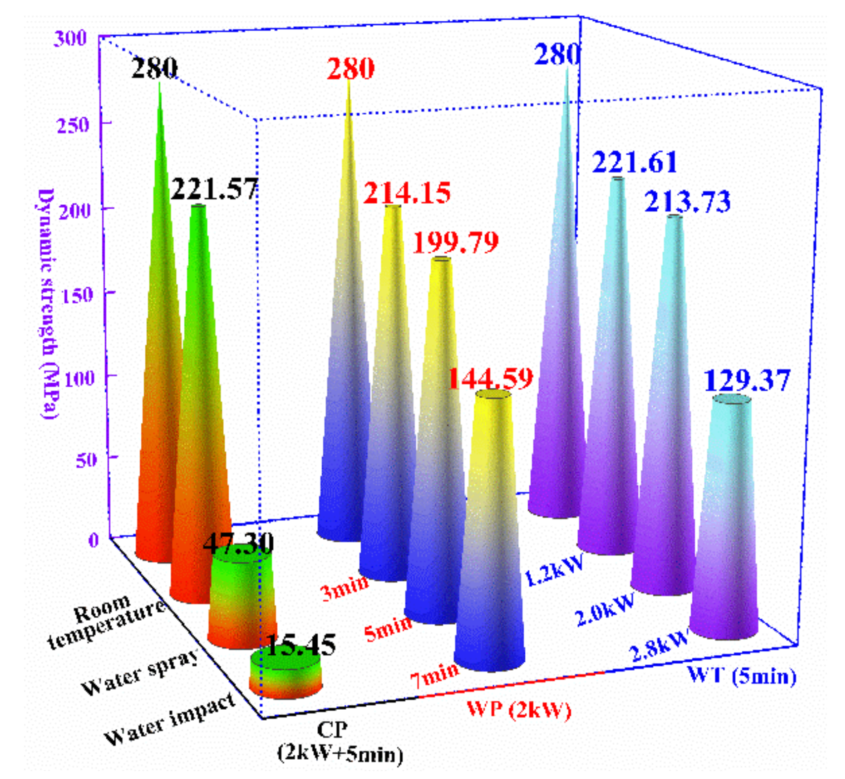
Figure 3.
Influence of microwave heating paths and cooling paths on absorbed energy and energy utilization.
Figure 3.
Influence of microwave heating paths and cooling paths on absorbed energy and energy utilization.
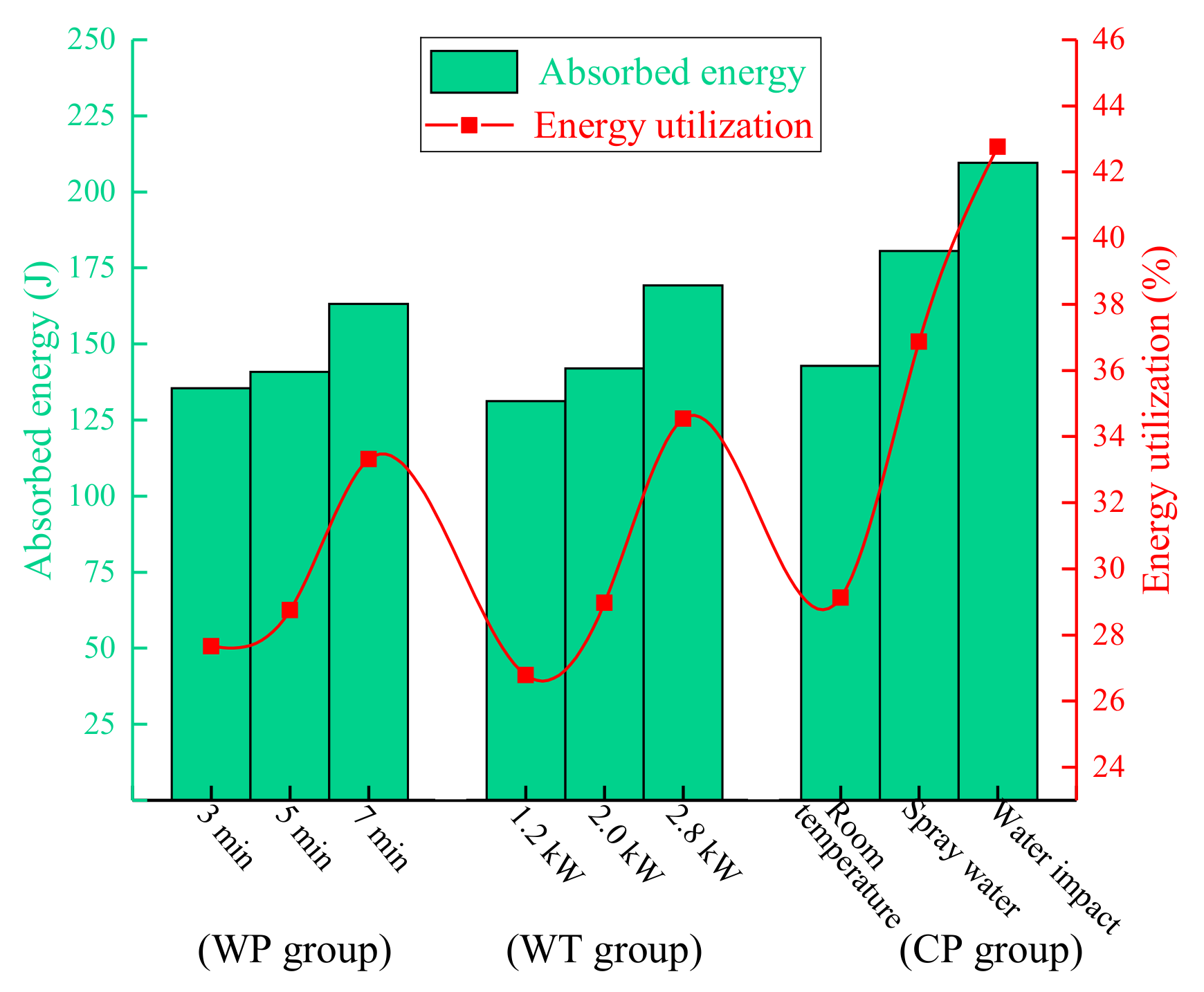
Figure 4.
Stress wave propagation at the interface between ore and platform.
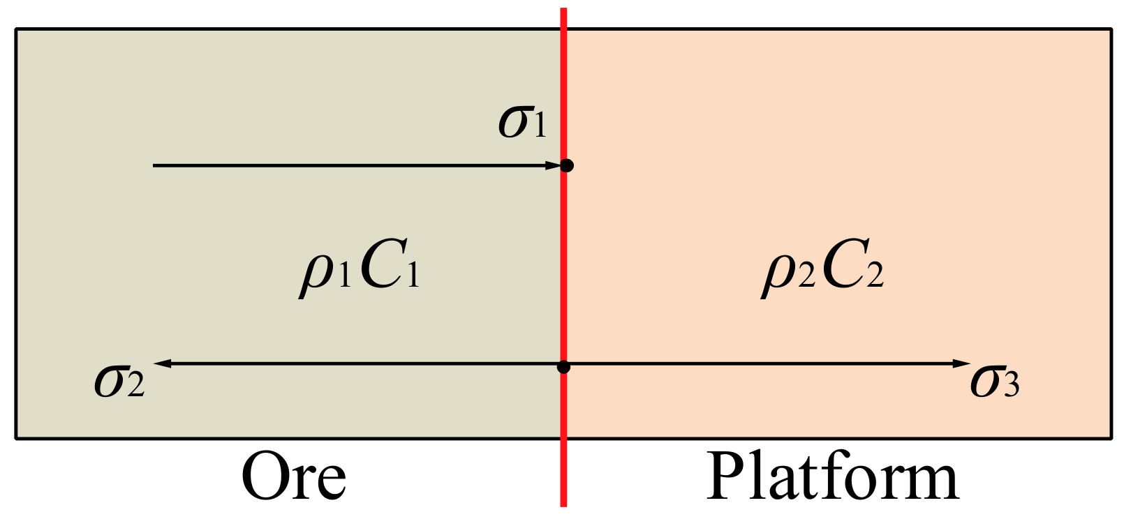
Figure 5.
Influence of microwave heating paths and cooling paths on and of ore.

Figure 6.
Main microstructure of magnetite ore. (a) flat morphology, (b) rough morphology.
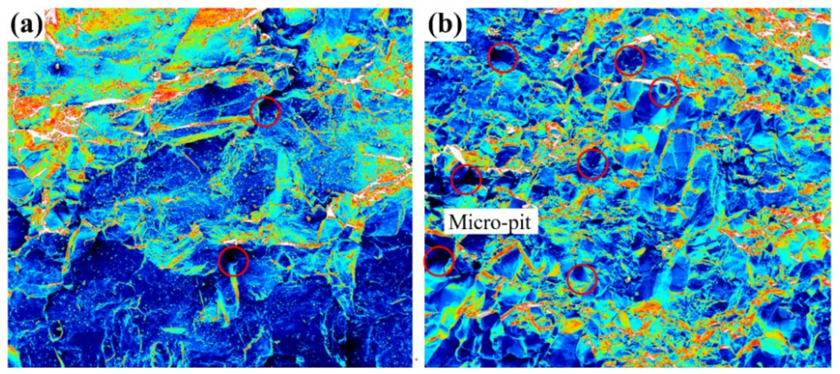
Figure 7.
The fracture morphology of ore after different irradiation time in group WP (2 kW). (a) 3 min, (b) 5min, (c) 7 min. T: transgranular cracks; I: intergranular cracks.
Figure 7.
The fracture morphology of ore after different irradiation time in group WP (2 kW). (a) 3 min, (b) 5min, (c) 7 min. T: transgranular cracks; I: intergranular cracks.
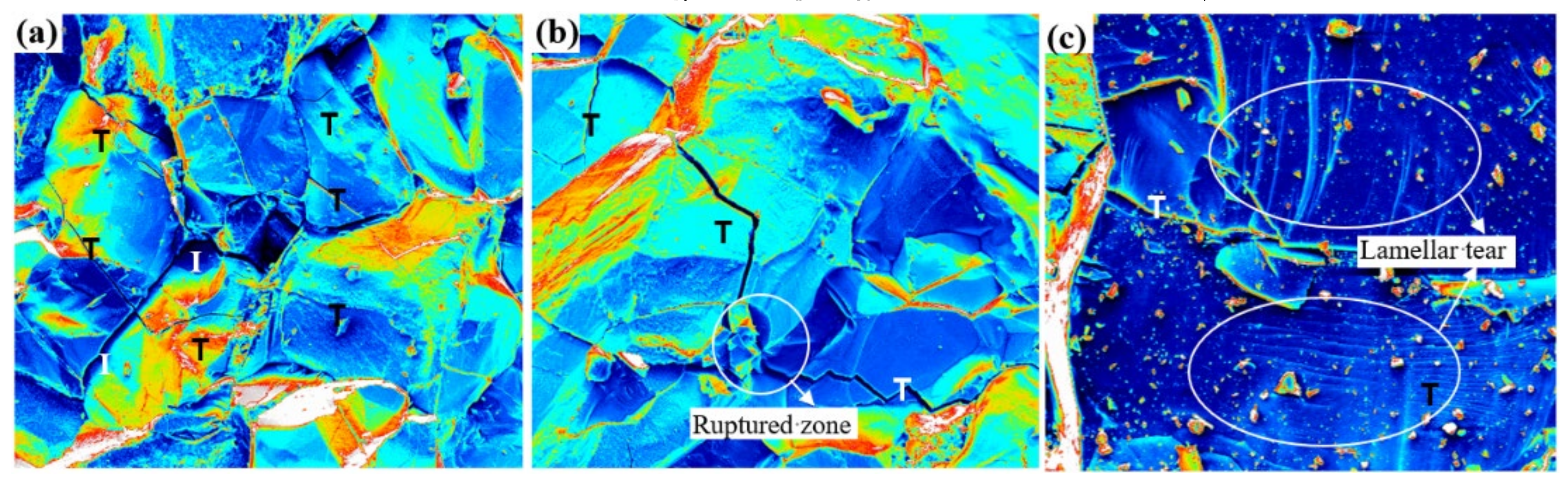
Figure 8.
The fracture morphology of ore after different irradiation powers in group WT (5 min); (a) 1.2 kW, (b) 2.8 kW. T: transgranular cracks; I: intergranular cracks.
Figure 8.
The fracture morphology of ore after different irradiation powers in group WT (5 min); (a) 1.2 kW, (b) 2.8 kW. T: transgranular cracks; I: intergranular cracks.
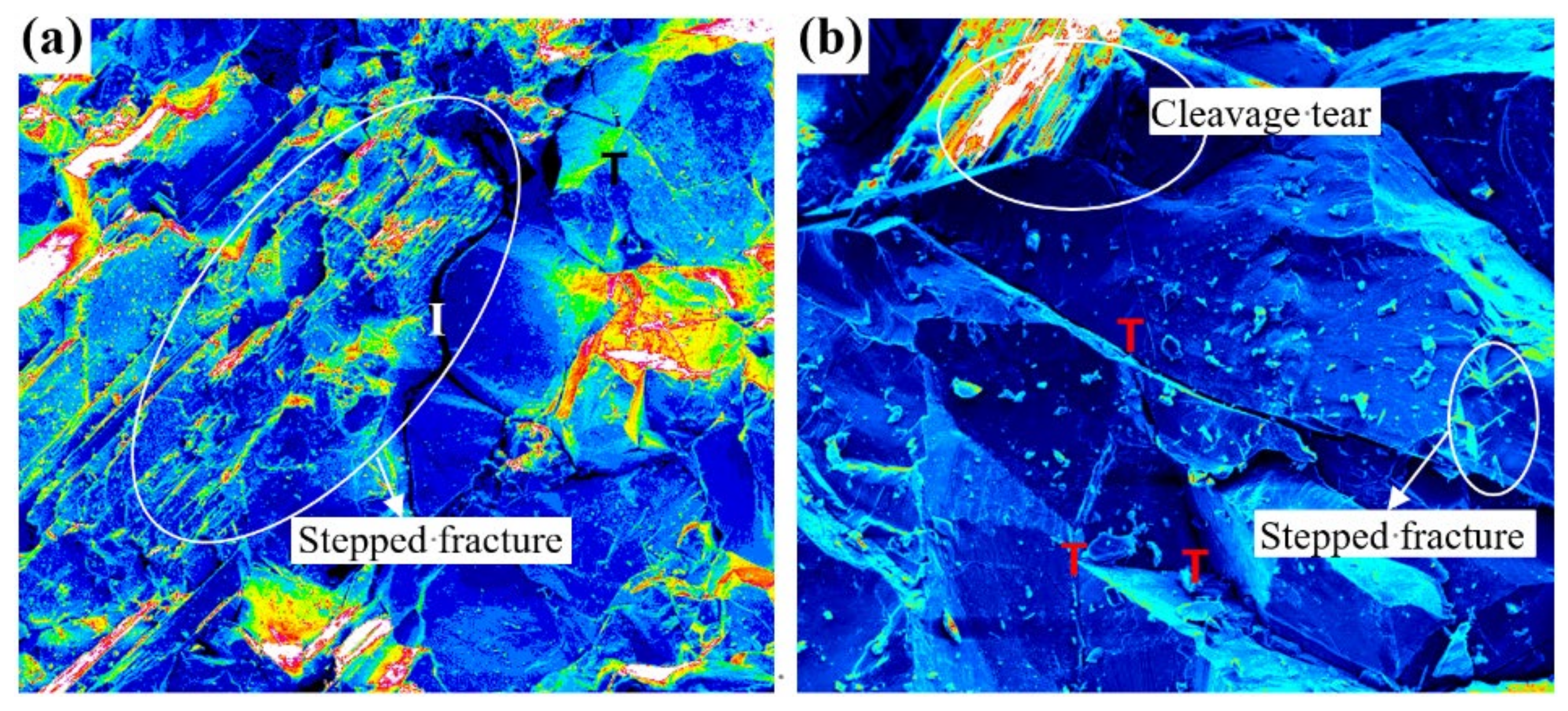
Figure 9.
The fracture morphology of ore cooled by spray water. T: transgranular cracks.

Figure 10.
Effects of microwave irradiation on the composition of several minerals. (1: calcite, 2: hornblende, 3: calcium feldspar, 4: magnetite, 5: hematite, 6: olivine, 7: enstatite, 8: albite, 9: quartz, A: microcline, B: lizardite, C: forsterite, D: pyroxene).
Figure 10.
Effects of microwave irradiation on the composition of several minerals. (1: calcite, 2: hornblende, 3: calcium feldspar, 4: magnetite, 5: hematite, 6: olivine, 7: enstatite, 8: albite, 9: quartz, A: microcline, B: lizardite, C: forsterite, D: pyroxene).
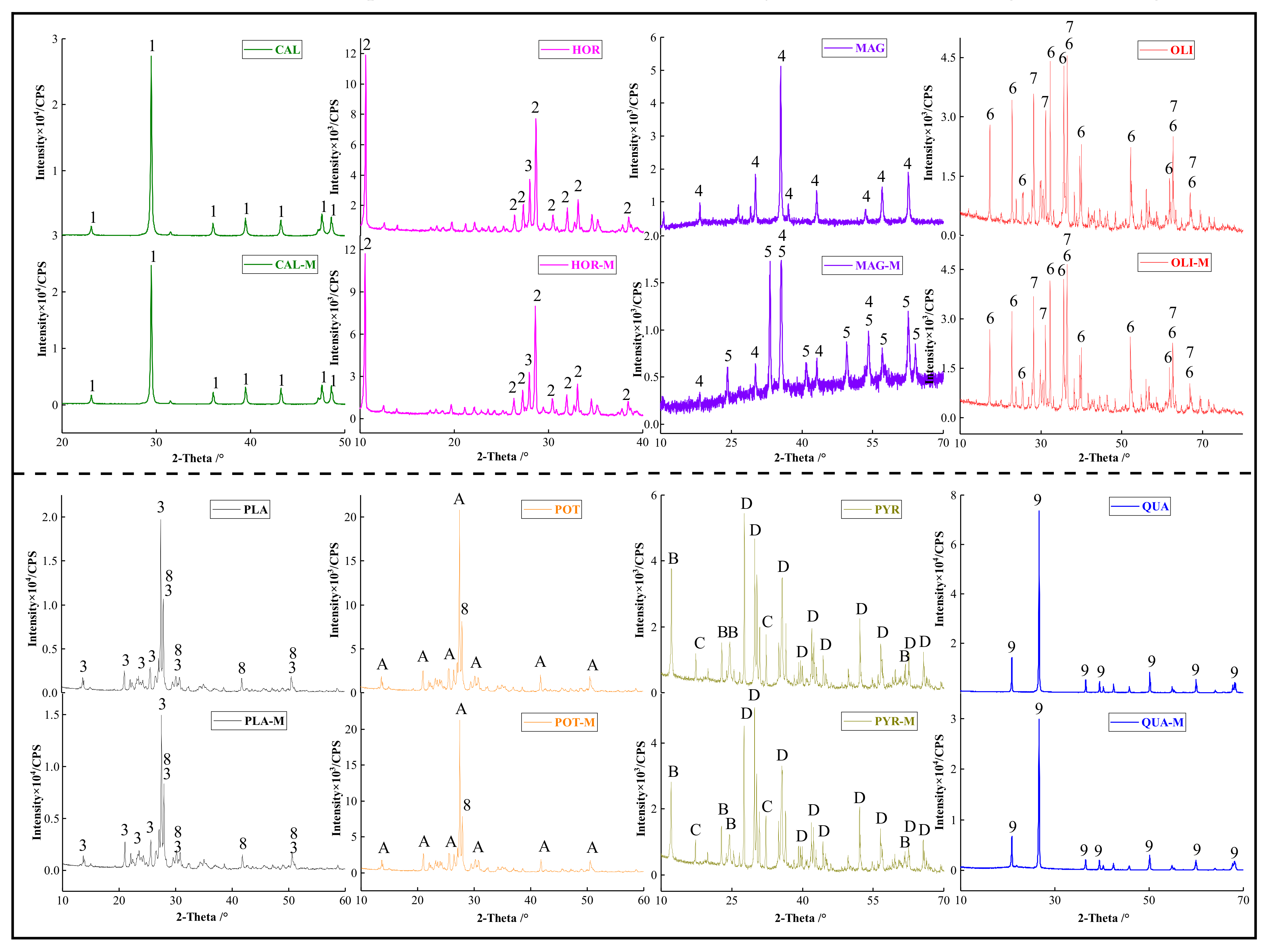
Figure 11.
Effects of microwave irradiation on the micromorphology of several minerals.
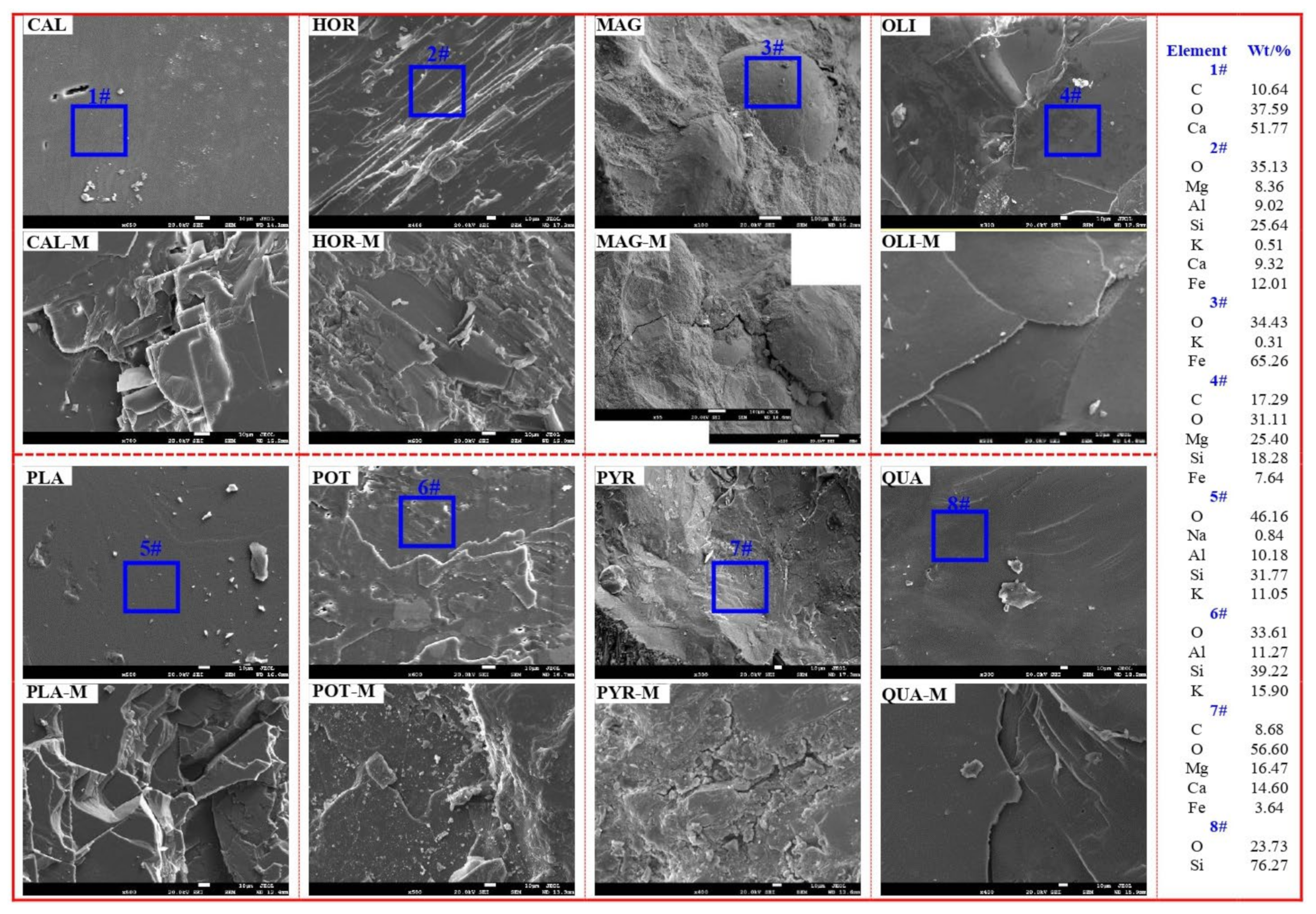
Figure 12.
Volumetric expansion coefficient of olivine, enstatite, and plagioclase.

Figure 13.
The escape of kinetic energy of fragments during ore crushing. (a–c) Ore treated by the microwave of 2 kW + 5 min, (d–f) ore treated by the microwave of 2 kW + 7 min.
Figure 13.
The escape of kinetic energy of fragments during ore crushing. (a–c) Ore treated by the microwave of 2 kW + 5 min, (d–f) ore treated by the microwave of 2 kW + 7 min.
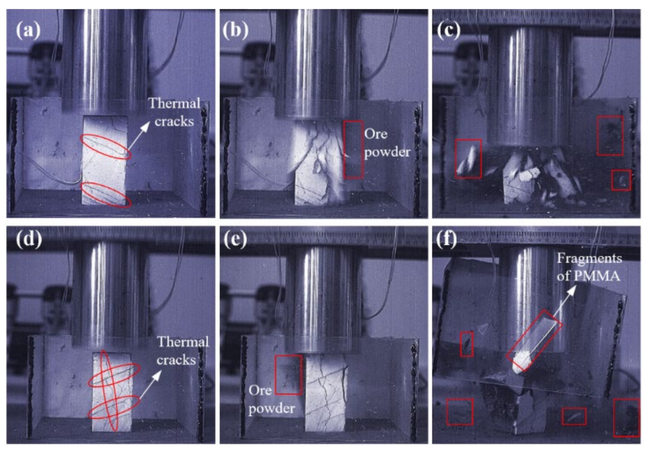
Figure 14.
(a) The absorbed energy and energy utilization in MSI, (b) total energy utilization, (c) average particle size.
Figure 14.
(a) The absorbed energy and energy utilization in MSI, (b) total energy utilization, (c) average particle size.

Figure 15.
Methods for rock cracking without explosion based on microwave irradiation.


Table 1.
Microwave parameters of each group and physical parameters of specimens. WP: same power + different time; WT: same time + different power; CP: cooling path group.
Table 1.
Microwave parameters of each group and physical parameters of specimens. WP: same power + different time; WT: same time + different power; CP: cooling path group.
| Group | Power/kW | Heating Time/min | Cooling Path | Number | Mass/g | Density/g·cm−3 | Wave Velocity/m·s−1 | Size/mm |
|---|---|---|---|---|---|---|---|---|
| WP | 2.0 | 3 | Room temperature | WP-3-1 | 815.29 | 3.25 | 3598 | 5.03 × 5.06 × 9.86 |
| WP-3-2 | 821.34 | 3.32 | 3682 | 4.98 × 5.02 × 9.90 | ||||
| WP-3-3 | 821.51 | 3.24 | 3596 | 5.02 × 5.05 × 9.99 | ||||
| 5 | WP-5-1 | 820.99 | 3.31 | 3677 | 5.03 × 4.93 × 10.00 | |||
| WP-5-2 | 825.51 | 3.32 | 3688 | 4.96 × 5.03 × 9.96 | ||||
| WP-5-3 | 818.02 | 3.28 | 3637 | 4.96 × 4.98 × 10.10 | ||||
| 7 | WP-7-1 | 821.78 | 3.26 | 3602 | 5.08 × 4.96 × 10.01 | |||
| WP-7-2 | 818.80 | 3.21 | 3574 | 4.99 × 4.97 × 10.27 | ||||
| WP-7-3 | 813.69 | 3.20 | 3559 | 4.97 × 5.09 × 10.05 | ||||
| WT | 1.2 | 5 | Room temperature | WT-1.2-1 | 816.49 | 3.23 | 3732 | 5.03 × 5.06 × 9.93 |
| WT-1.2-2 | 822.37 | 3.30 | 3668 | 4.99 × 4.92 × 10.16 | ||||
| WT-1.2-3 | 821.30 | 3.29 | 3651 | 5.11 × 4.91 × 9.95 | ||||
| 2.0 | WT-2.0-1 | 817.15 | 3.26 | 3586 | 5.07 × 5.02 × 9.85 | |||
| WT-2.0-2 | 815.32 | 3.29 | 3644 | 5.02 × 4.96 × 9.95 | ||||
| WT-2.0-3 | 822.75 | 3.32 | 3705 | 5.01 × 5.05 × 9.80 | ||||
| 2.8 | WT-2.8-1 | 822.31 | 3.31 | 3679 | 5.03 × 4.97 × 9.93 | |||
| WT-2.8-2 | 819.56 | 3.28 | 3640 | 5.02 × 4.96 × 10.04 | ||||
| WT-2.8-3 | 820.06 | 3.35 | 3729 | 4.94 × 4.91 × 10.09 | ||||
| CP | 2.0 | 5 | Spray water (SW) | CP-SW-1 | 821.66 | 3.28 | 3628 | 4.96 × 5.03 × 10.03 |
| CP-SW-2 | 817.15 | 3.30 | 3657 | 5.10 × 4.82 × 10.07 | ||||
| CP-SW-3 | 820.53 | 3.26 | 3615 | 4.89 × 5.14 × 10.01 | ||||
| Water impact (WI) | CP-WI-1 | 818.75 | 3.34 | 3620 | 5.07 × 4.88 × 9.90 | |||
| CP-WI-2 | 820.44 | 3.33 | 3714 | 4.92 × 5.11 × 9.80 | ||||
| CP-WI-3 | 817.34 | 3.24 | 3596 | 4.99 × 5.02 × 10.06 |
Table 2.
Micromorphology characteristics of the ore fragments.
| Groups | Heating Path | Cooling Path | Microstructure | Fracture Mechanism | Energy Consumption |
|---|---|---|---|---|---|
| WP | 2KW + 3min | Room temperature | Step-like morphology | I-fractures | Low |
| 2KW + 5min | |||||
| 2KW + 7min | Lamellar tear | T-fractures, lamellar tear | Medium | ||
| WT | 5min + 1.2 KW | Shell-like and step-like | I-fractures | Low | |
| 5min + 2.8 KW | Cleavage tear, flat morphology | T-fractures, cleavage tear | Medium | ||
| CP | 2KW + 5min | Spray water | Flat morphology, micro-pits | T-fractures | High |
Table 3.
The MSI crushing scheme.
| Scheme Name | Number of Ore | /mm | /mm | /mm | /mm |
|---|---|---|---|---|---|
| MSI-A | 3 | 250 | 350 | 450 | 1050 |
| MSI-B | 3 | 350 | 250 | 450 | 1050 |
| MSI-C | 3 | 450 | 350 | 250 | 1050 |
| SSI | 3 | 0 | 1050 | ||
Publisher’s Note: MDPI stays neutral with regard to jurisdictional claims in published maps and institutional affiliations. |
© 2021 by the authors. Licensee MDPI, Basel, Switzerland. This article is an open access article distributed under the terms and conditions of the Creative Commons Attribution (CC BY) license (https://creativecommons.org/licenses/by/4.0/).
Share and Cite
MDPI and ACS Style
Hao, J.; Li, Q.; Qiao, L. Study on Magnetite Ore Crushing Assisted by Microwave Irradiation. Minerals 2021, 11, 1127. https://doi.org/10.3390/min11101127
AMA Style
Hao J, Li Q, Qiao L. Study on Magnetite Ore Crushing Assisted by Microwave Irradiation. Minerals. 2021; 11(10):1127. https://doi.org/10.3390/min11101127
Chicago/Turabian StyleHao, Jiawang, Qingwen Li, and Lan Qiao. 2021. "Study on Magnetite Ore Crushing Assisted by Microwave Irradiation" Minerals 11, no. 10: 1127. https://doi.org/10.3390/min11101127
Note that from the first issue of 2016, this journal uses article numbers instead of page numbers. See further details here.