Symmetry Aspects of Dislocation-Effected Crystal Properties: Material Strength Levels and X-ray Topographic Imaging


Abstract
: Several materials science type research topics are described in which advantageous use of crystal symmetry considerations has been helpful in ferreting the essential elements of dislocation behavior in determining material properties or for characterizing crystal/polycrystalline structural relationships; for example: (1) the mechanical strengthening produced by a symmetrical bicrystal grain boundary; (2) cleavage crack formation at the intersection within a crystal of symmetrical dislocation pile-ups; (3) symmetry aspects of anisotropic crystal indentation hardness measurements; (4) X-ray diffraction topography imaging of dislocation strains and subgrain boundary misorientations; and (5) point and space group aspects of twinning. Several applications are described in relation to the strengthening of grain boundaries in nanopolycrystals and of multiply-oriented crystal grains in polysilicon photovoltaic solar cell materials. A number of crystallographic aspects of the different topics are illustrated with a stereographic method of presentation.1. Introduction
Neumann's Principle, stating that the symmetry elements of a crystal property must follow the same directional characteristics associated with the point group of the crystal structure [1], is shown here to be usefully connected in a number of instances with the lattice structure dependent behavior of crystal dislocations that play a major role in determining the physical and mechanical properties of materials, say compared to specification of the intrinsic lattice character of the elastic constant tensor.
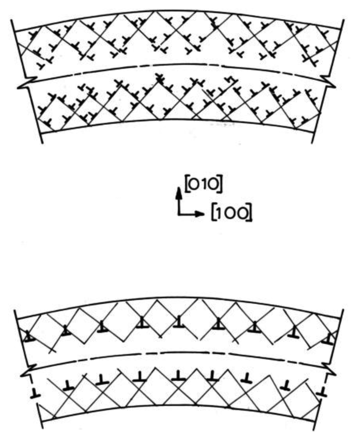
A first dislocation example is provided by the weak piezoelectric effect induced in plastically-bent NaCl (rocksalt) crystals after insertion of a cumulative dislocation structure [2]. Figure 1 illustrates the modeled dislocation structure as inverted T's created by plastic bending around the [001] direction crystal axis. Dislocations of the same sign are produced in both the tension and compression surface layers. The net effect is modeled with multiple Burgers vector dislocations [2]. The average trapezoidal structure of the bent crystal makes it eligible for being piezoelectric according to the Neumann Principle whereas the detailed characteristics of the weakly-piezoelectric behavior are understood in terms of the displacement of the electrically-charged dislocation structure.
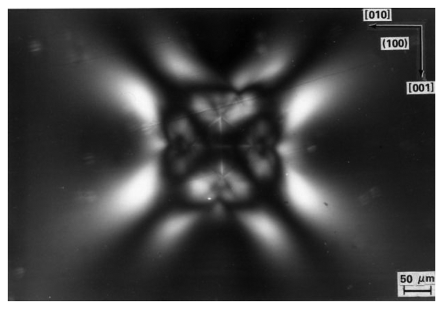
A further example that is to be described in detail in the present report is shown in the transmission image of polarized light shown in Figure 2. In this case, an aligned diamond pyramid microhardness indentation has been impressed into an (001) LiF crystal surface in such manner that the indenter diagonal directions were aligned along the cube <100> directions of the crystal. The slightly convex shape of the otherwise square projection of the residual hardness impression is seen in white outline at the center of the symmetrical image pattern of polarized light transmitted through both the indentation and much larger surrounding region of plastic deformation. As will be discussed in relation to a number of observations to be made concerning crystal hardness properties, the plastic deformation structure in this case, and in some other cases associated with consequent cleavage cracking, are intimately dependent on the edge or screw type character of the induced dislocation network remaining within the residual deformation zone [3]. A number of other materials science type examples are also to be described in the present report involving extension of crystal dislocation model considerations to selected symmetry aspects of polycrystal and polyphase material structures.
2. Deformation of Symmetrical Aluminum Bicrystals
The first half of the 20th century was taken up with investigation of the plastic deformation properties of single crystals, for example, as described in an early account given by Schmid and Boas for both metal and mineral crystal systems [4] and also featuring measurements of crystal anisotropic elastic constant coefficients. The latter part of the century began with reports of the strength dependence of polycrystalline steel on the inverse square root of average grain diameter [5]. An early experiment designed to assess the crystal/polycrystal connection [6] is characterized in Figure 3 [7].
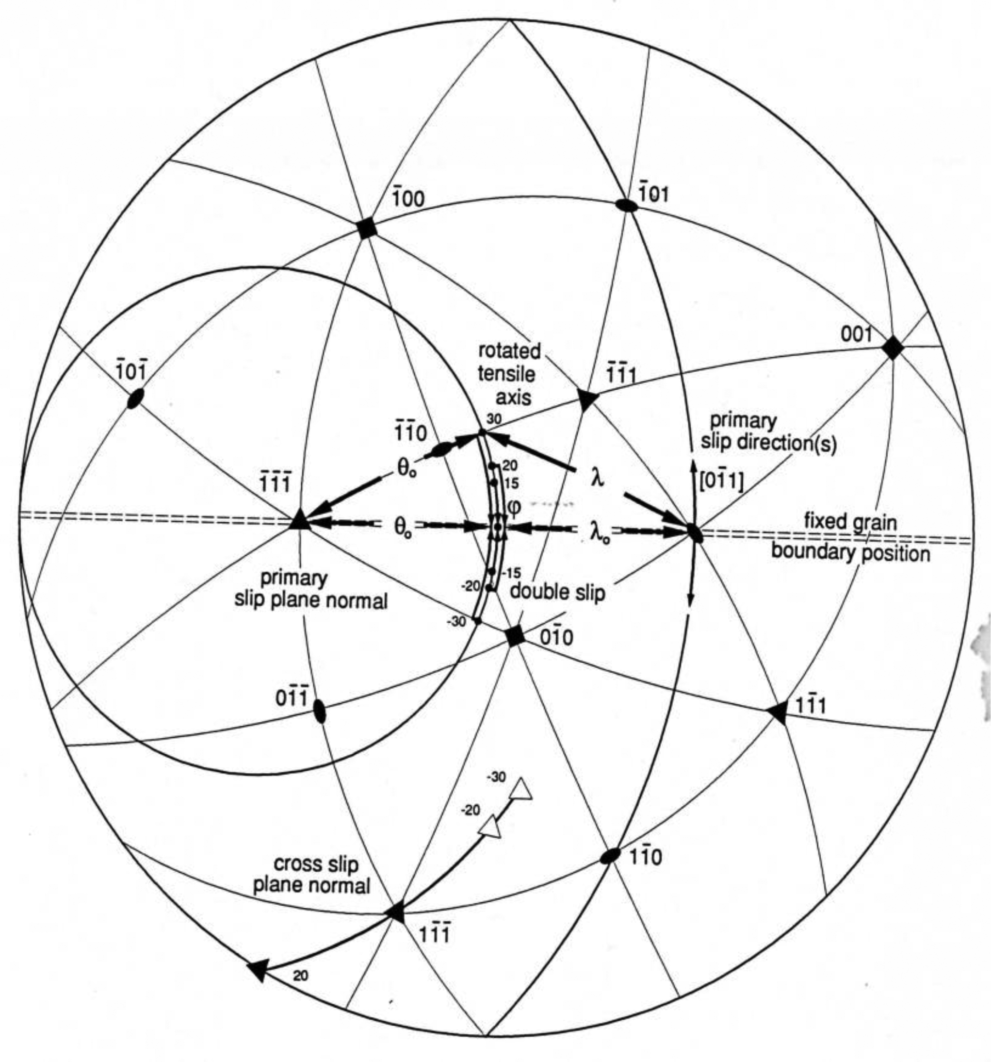
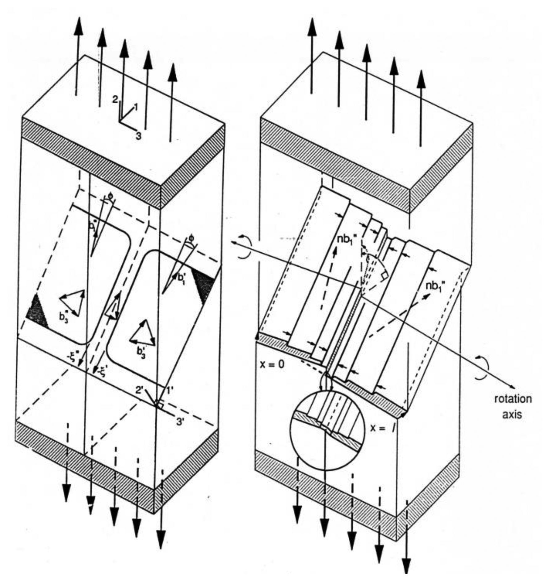
Clark and Chalmers [6] devised the symmetrical bicrystal experiment for investigation of the simplest case of dislocation slip being hampered in penetrating a single “grain” boundary obstacle. The experiment is illustrated on the left side of Figure 3 [7]. On the right side of the figure, attention is given to the need for cross-slip to occur to relieve the local strain at the boundary. Figure 4 provides a stereographic method of analysis for tracking the cross-slip required because of the mis-match of slip penetrations coming from independently activated slip systems on either side of the boundary [7].
In Figure 4, one is looking down from the tensile axis (TA) direction onto the centered bicrystal boundary seen as the equatorial diameter of the great circle tied to the crystal orientation. An initial (bi)crystal orientation had been chosen such that the (1̅1̅1̅) slip plane normal is shown at 45° to the TA on the left equatorial position and the primary [01̅1] slip direction is on the right side of the equator, also at 45°. The various TA positions for different bicrystal boundary misorientations, whose deformation properties were investigated at rotations of ±15°, ±20° and ±30° are marked on the small circle axis positions above and below the equator. Very interestingly, double slip is predicted to occur with addition of the (1̅1̅1) slip plane and [01̅1̅] slip direction for the one crystal at the symmetrical TA position of −15° rotation and to produce consequent added strain hardening because of double slip occurring and causing subordination of the grain boundary hardening effect. A modern account of such aluminum bicrystal deformations that was forced within the confinement of a channel die has been given in terms of a finite element model and a need at larger boundary misorientations for dislocation pile-ups to produce changes in orientation accompanying the plastic deformation [8].
In fact, aluminum is now known to produce the weakest influence of grain boundaries on strengthening of any polycrystalline material [9]. A compilation of so-called Hall-Petch reciprocal square root of grain size dependent strength measurements made on many aluminum materials of differing purity had been reported by Wyrzykowski and Grabski who also raised the issue of grain boundary diffusivity for relaxation of local grain boundary straining [10]. Otherwise, the principal reason for needed stress concentrations in the grain boundary regions of aluminum and other face-centered cubic metals is traced in Figures 3 and 4 to the need for cross-slip to occur at the tips of dislocation pile-ups in order to assist also in providing continuity of strains at the boundary interfaces [11]. The (11̅1̅) plane normal cross-slip positions are shown for several TA axis positions relative to the primary slip system in Figure 4 while the manner in which such cross-slip compensates in part for strain incompatibility is shown schematically in Figure 3. Aluminum has a very low resolved shear stress for cross-slip because of its high stacking fault energy.
3. Cleavage Cracking Produced by Symmetrical Dislocation Pile-Ups
Iron and steel materials, for which the Hall-Petch relation had initially been established, provide an opposite case from aluminum of a very strong grain size dependence for the yield point behavior and even greater for the cleavage fracture stress [12,13], typical of body-centered cubic (bcc) materials. In connection with a report on the grain size dependence of cleavage fracturing, a breakthrough explanation was provided by Cottrell of such cleavages occurring at the crystal lattice scale in steel and related bcc metals and alloys [14]. Slip at symmetrically intersecting dislocation pile-ups was proposed to produce a crack-initiating sessile dislocation in accordance with the vector relation
In Equation (1), mixed dislocations of Burgers vector b = (a/2) [11̅1] on the (110) slip plane and (a/2)[111̅] on the (11̅0) slip plane meet along the [001] direction of the plane intersections and combine to form an edge dislocation of Burgers vector (a)[100]. The reacted edge dislocation, being immobile on the potential (010) plane that is normally not a slip plane in the bcc lattice, is taken to be the nucleus for cracking on the established {100} cleavage plane of the bcc lattice.
Despite the finally reacted dislocation being of lower energy than the sum of the individual reactant dislocations, it has been presumed that the reaction is forced to occur by coupled dislocation pile-ups pushing from behind on the respective {110} slip planes. Chou, Garofalo and Whitmore made use of the symmetrical disposition of the slip systems and dislocation Burgers vectors in computing the pile-up stress characteristics associated with the requirement of cleavage fracturing [15]. The crystal elastic anisotropy was taken into account in the computations. An appreciably reduced number of pile-up dislocations on each slip system was found to be necessary for cleavage to occur. Antolovich and Findley have re-examined the model to establish that a repulsive obstacle stress is overcome in forming the (a) [100] crack nucleus [16]. Armstrong and Antolovich have reported on the model consideration when small numbers of dislocations might be involved in the pile-ups, for example, in the case of nanopolycrystalline materials where the slip plane lengths are restricted to nanoscale dimensions [17]. Under such circumstance, it was shown that the normal large-dislocation-number effect of equivalence between a dislocation pile-up and a continuum-type shear crack ceases to be valid. The computation was proposed as an explanation of cleavage cracking not being found in the fracturing of nanopolycrystalline iron material [18].
4. Symmetry Aspects of Crystal Microhardness Indentations
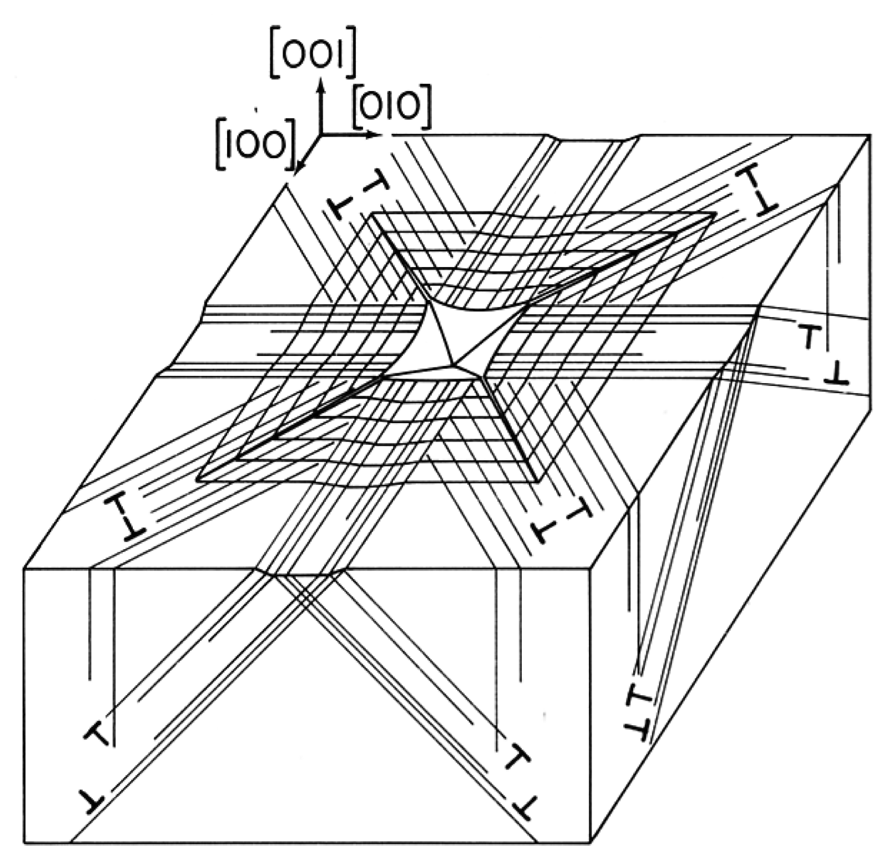
Illustration of the broader application of Cottrell's model explanation for plastically-induced cleavage is demonstrated schematically in Figure 5 for 4-fold crack initiations occurring along the diagonal directions just outside of the corners of aligned microhardness indentations put into the (001) surface of an MgO crystal [19]. The dislocation reaction leading to such otherwise unfavorable {110} plane cracking had been described by Keh, Li and Chou [20] in an analogous manner to that described by Chou et al. [15]. In this case, the crack-forming reactions occur on juxtaposed {110} slip planes intersecting along <111> type directions between dislocations of <11̅0> type Burgers vectors [21].
It should be noted that the same dislocation pattern shown in Figure 5 would apply as well for the indentation shown in Figure 2 of a LiF crystal indentation viewed in transmitted polarized light. As previously mentioned, the dislocation pattern produced in LiF of a slightly convex shape may be compared with the concave appearance of the residual indentation shown in Figure 5. Both shapes have been produced for analogous indentation alignments in MgO [19]. And very importantly relative to Figure 5, the edge dislocation dipole structures shown along <110> type directions may now be seen to match the contrast pattern in Figure 2 whereas the shear character of the screw dislocation arrays extending along <100> type directions produces negligible contrast. The inner compressive (dark) and outer tensile dilatational (white) stress state produced along <11̅0> in Figure 2 agree with a pioneering description by Mendelson of the birefringent character of individual slip band structures [22].
The residual strain patterns at such indentations in MgO crystals also provided ready specimens for investigation via X-ray diffraction imaging [19], as shown in an X-ray reflection topographic image of Figure 6 [23]. The surface-projected indenter diagonal edges are aligned along <110> directions as for Figure 5. The central white square patterns of absent X-ray intensity correspond to the appreciably distorted “picture frame” shown schematically in Figure 5. An enhanced (blackened) X-ray intensity of diffraction contrast is attributed to reduced extinction of the diffracted beam. In this case, there is essentially no diffraction contrast along the diagonal <110> directions because of the smaller range of strain associated with the dislocation dipole structure, rather than the cumulative strains associated with the screw dislocation arrays extending along the <100> directions. The approximate vertical mirror plane symmetry of each diffraction image is attributed to the asymmetry of the laterally directed incident and diffracted X-ray beams.
5. X-ray Topography of Symmetrical-Tilt Crystal Subgrain Boundaries
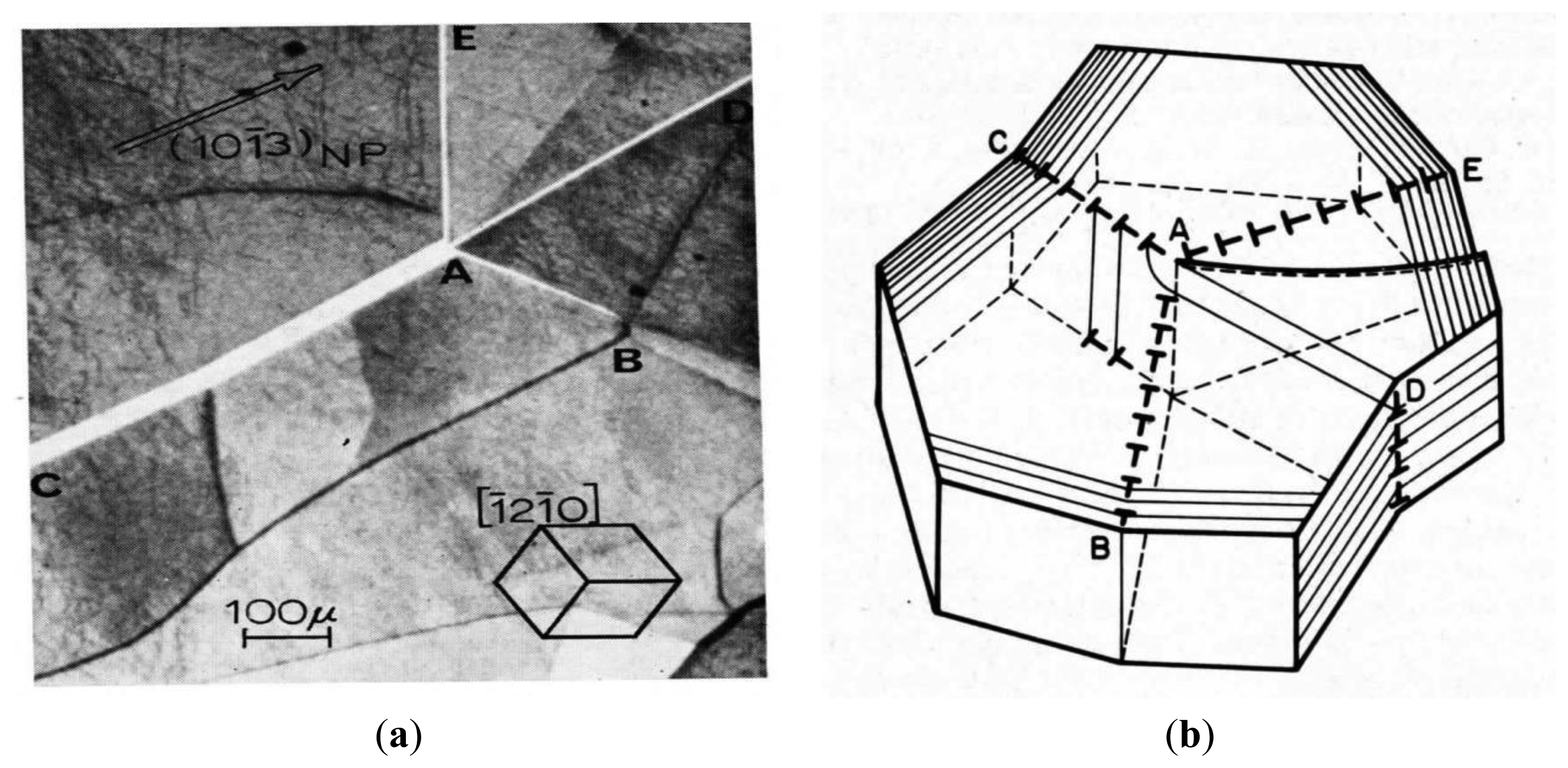
The background structure in Figure 6 of seemingly meandering black or white boundaries between adjacent crystal subgrains and the left-to-right downwardly inclined black cleavage steps (for the incident X-ray beam “looking in”) are also of interest in relation to understanding the defect structure of conventional imperfect single crystals at the larger scale of a “mosaic” structure, as historically hypothesized in quantitatively accounting for X-ray diffracted intensity measurements. The mostly vertical white boundary in Figure 6 is caused by the small angle separation of the adjacent subgrain reflections as compared with the two approximately horizontal black boundaries of overlapping images. Such mosaic or lineage-type symmetrical dislocation “tilt” boundaries that are formed especially in melt-grown crystals are intimately determined by the crystal growth conditions and relate to preferred atomic-scale directions of crystal phase transformations. For example, zinc and related hexagonal crystals show a preference for solidification along directions contained in the hexagonal basal plane. One such example of an [0001] direction crystal growth structure of subgrains and dislocation network within them is shown in Figure 7a,b through the (0001) cleavage plane of a zinc crystal rod [24]. The model description of the subgrain boundary characterizations was obtained by means of the changed “misorientation contrast” seen in different {101̅3} topographs. And of particular note is the orientation of the dislocation lines climbing into [0001] directions during the slow crystal solidification procedure, as compared with a preference to reside in the (0001) basal plane.
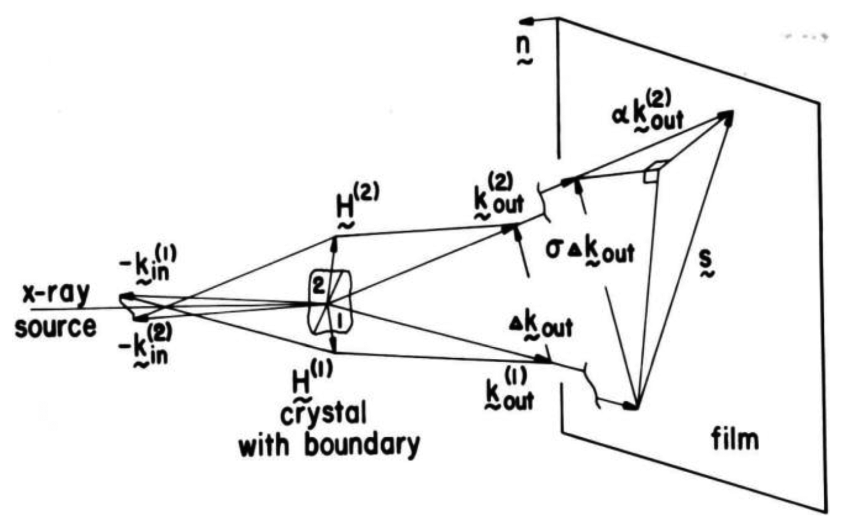
A similar analysis to that described for zinc was reported for the preferred [010] orientation of crystal subgrain boundary misorientations in the solidification of nickel single crystals [25]. Figure 8 shows the diffraction geometry developed in a wave vector description of two subgrain reflections being obtained with an asymmetric crystal topography (ACT) system.
In Figure 8, the vector separation, s, of two immediately adjacent points on either side of the crystal boundary was evaluated in terms of the distance to the X-ray film, d, the difference in reciprocal diffracting plane lattice vectors, ΔH, and different incident beam wave vectors, Δk, as
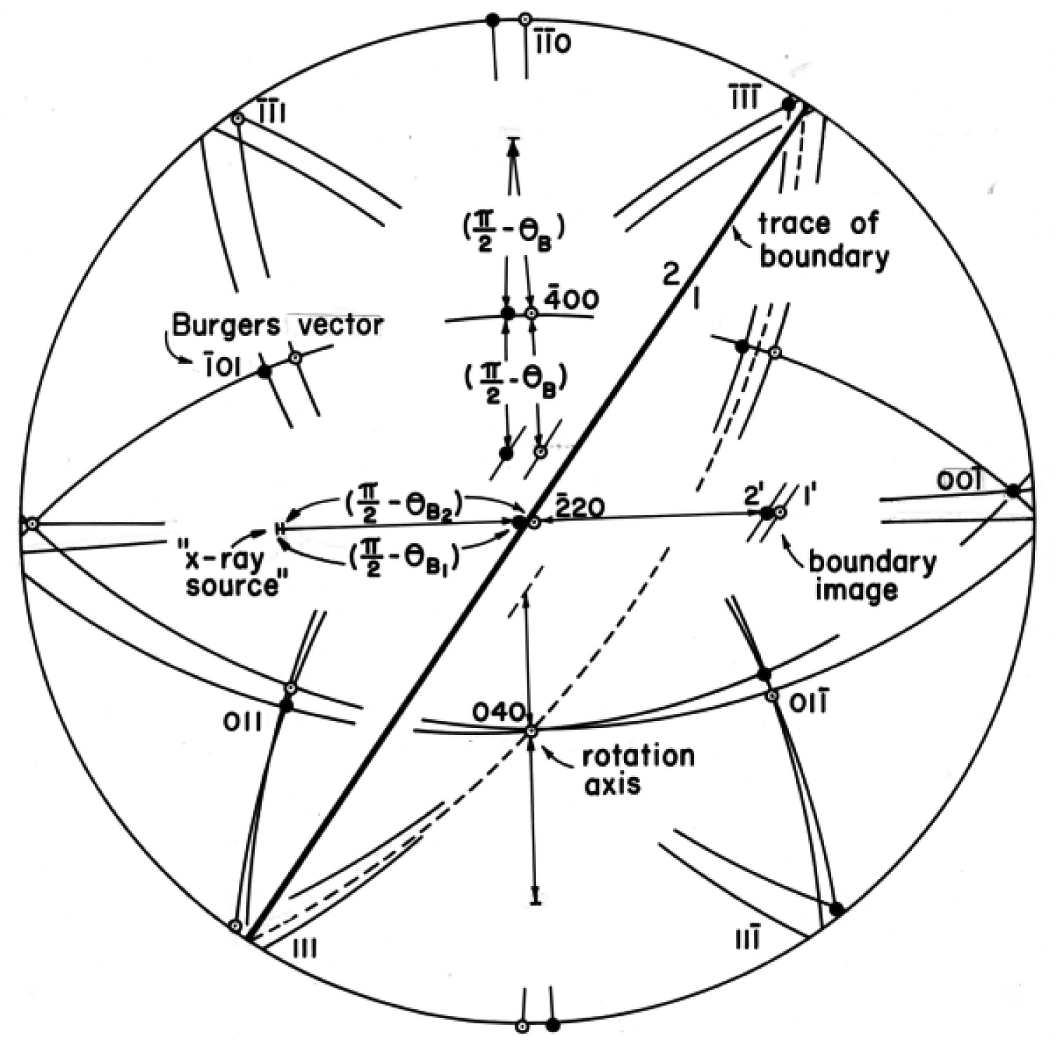
Figure 9 is an example stereographic projection of the thus determined misorientation of a subgrain boundary in a solidified nickel crystal and determined [010] rotation axis for it. In Figure 9, two incident X-ray beams from nearby points on the X-ray source satisfy respectively the Bragg (reflection) condition for subgrains 1 and 2 in the equatorial plane for (2̅20) plane reflections. And the same is shown for the rotated (crystal; position of a single beam producing both subgrain reflections along the vertical diametral great circle. The displaced X-ray reflection points were then traced on orthogonal great circles to determine by intersections the axis of rotation for the subgrain misorientation.
6. Point and Space Group Aspects of Twinning
Growth twinning and deformation twinning also exhibit interesting aspects of crystal symmetry that have an extensive background history and yet are currently the subject of intensive researches into the detailed atomic or molecular displacements that are involved in transition from the host crystal structure. Figure 10 is a schematic representation of a (101̅2) plane with [101̅1̅] twinning direction deformation twin propagating inward from the surface of a zinc single crystal [26]. Such twins often have associated kink (or dislocation tilt) boundaries associated with them in order to effect accommodation with the un-twinned matrix crystal volume. And often, an additional twin will propagate along the accommodation boundary of the first one, and so on.
Even for twinning in the relatively simple hexagonal close-packed crystal structure of zinc, cadmium and magnesium, there is the complication of needed atomic re-arrangements, or shuffle displacements, that are required to produce a mirror image twin volume relative to the matrix crystal lattice [26]. The effect is illustrated, for example, in description of deformation twinning of the molecular crystal, HMX (cyclotetramethylenetetranitramine, [CH2·N·NO2]4, as illustrated in Figure 11 for a type II rotational twinning model also with indicated molecular adjustments. Quite interestingly, HMX is known to deform principally by deformation twinning whereas the smaller molecular counterpart RDX (cyclotrimethylenetrinitramine), [CH2·N·NO2]3 lattice is known to deform principally by slip. The ease of twinning was attributed to greater flexibility of the larger HMX molecule [27,28].
7. Discussion
Each of the topics described thus far relate in one way or another to the strength properties of individual crystals and even more so to their aggregation in a polycrystalline (or polyphase) structural material. The crystal, or more often specified grain, size of a polycrystalline has been known, beginning from the 18th century, to influence material strength and fracturing properties, as recently reviewed [11].
7.1. Crystal Sizes and Dislocation Pile-Ups
The symmetrical bicrystal strength measurements described with respect to Figure 3 were obtained for aluminum that exhibits the weakest crystal or grain size dependence. The strength is specified most often in terms of the plastic flow stress, σε, following a Hall-Petch reciprocal square root of grain diameter, ℓ dependence, with experimental constants, σ0ε and kε:
McGrath and Craig [29] had reported on the resolved shear stress dependence on variation in subgrain spacing of “striations” obtained in single crystals of aluminum grown at different solidification rates; and Fleischer [30] determined a value of kε = 1.1 MPa·mm1/2 for ℓ in Equation (3) taken as the crystal subgrain size. The value of kε is essentially the same as that determined from the σε dependence on ℓ for polycrystalline material [11] and which value has been attributed to kε being taken as a microstructural stress intensity needed for cross-slip [9]. An important stereological description of the development of subgrain boundaries within the deformed grain structure of aluminum polycrystals has been given recently [31]. An example of the hierarchical nature of several levels of substructure in metal crystals is illustrated in the X-ray ACT-type topograph of Figure 12 that was obtained in relation to the analysis described for Figure 8.
Also, the schematic description in Figure 3 of cross-slip assistance in accommodating transmission of plastic strain at the bicrystal boundary relates to the physical explanation of the relatively low kε value measured for aluminum that exhibits a lowest value of resolved shear stress for cross-slip. The cross-slip plane for the experiments of Craig and Chalmers is shown in the stereographic representation of Figure 4. Regarding measurement of the low kε value for aluminum, that value for the iron and steel materials on which the Hall-Petch relation was originally based was a much larger measurement of ∼24 MPa·mm1/2 caused by carbon locking of dislocations at grain boundaries [32]. And a much larger values of kε = kC = ∼120 MPa·mm1/2 applies for cleavage of steel also in line with the pile-up stress concentration required to produce cracking at the symmetrical slip plane intersections shown schematically for an MgO crystal in Figure 5 [19,23].
7.2. Polycrystal Application of X-ray Topographic Imaging
Polycrystalline X-ray diffraction topography was achieved for individual grain reflections in pioneering research measurements reported by Weissmann [33]—far before synchrotron X-ray diffraction topography was available both for individual grain reflections and for multiple reflections from within a grain. Early reviews on the several methods of reflection and transmission X-ray topography are given in references [34,35]. A recent review is given by Moore [36], particularly relating to orders of magnitude reduction in both time and beam divergence capabilities that are available with synchrotron radiation.
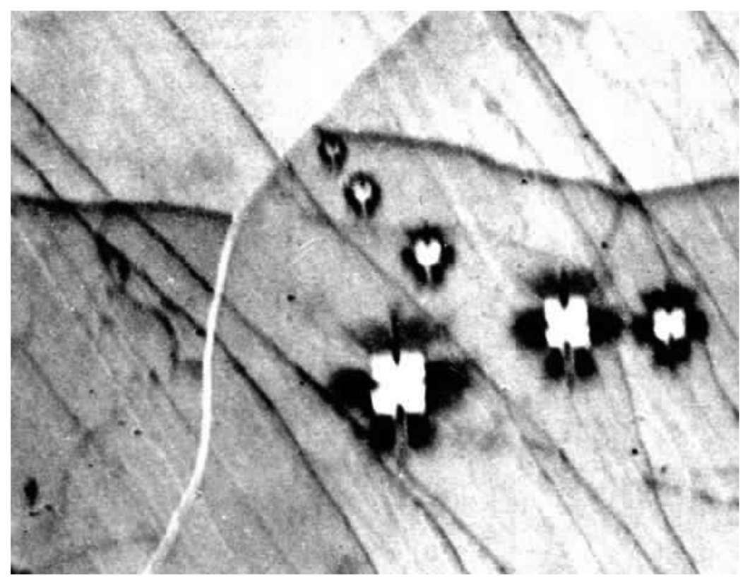
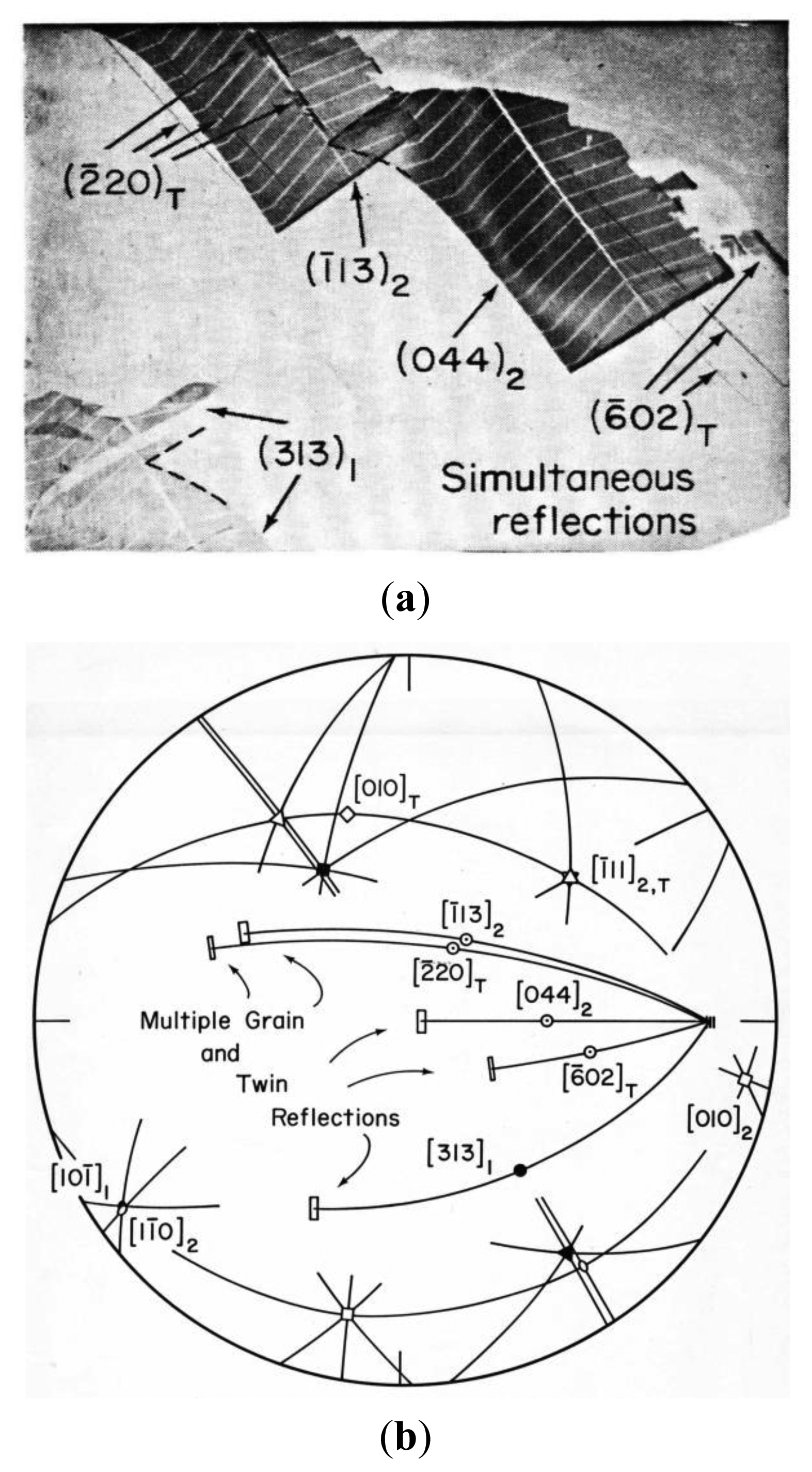
Notable applications of the topographic methods have involved electronic semiconducting materials ranging from essentially perfect crystals to specially-oriented polysilicon materials. In the latter case, use has been made of the occurrence of symmetry aspects of Σ-type boundaries for which the polycrystalline grain orientations are related through multiple twinning operations [37]. Figure 13a,b shows such a case for simultaneous reflections able to be obtained from a photovoltaic solar cell fabricated on a cast polysilicon material with such Σ-type boundaries [38].
The topographic images shown in Figure 13a had been obtained from a fabricated cell with metallization chevrons in place and that are recognized by their absorption of the X-ray beam. Grain 2 is marked by its subscripted number on the several topographic reflections that may be seen to have top ends fitted into the dashed angular inset image shown in the lower left hand corner of the figure. Grains 1 and 2 have a Σ-type orientation relationship shown in Figure 13b of ∼39° rotation about the common <110> type direction shown for the specific index labels in the third quadrant of the stereographic projection. The special orientation relationship between the grains allowed the multiple topographic reflections to be obtained. A number of twins were present in grain 2 and their reflections are indexed also in Figure 13a,b. The reduction in photoresponse measurements at the grain boundaries were reasoned to be less than would be the case for an arbitrary misorientation between the grains. Hardouin Duparc has recently reviewed the history of grain boundary studies in relation to a broader description of such orientation relationships in a variety of materials [39].
8. Summary
A number of symmetry-related research topics have been described in relation to crystal and polycrystal strength measurements and in relation to imaging of crystal and polycrystal substructures through the use of X-ray diffraction topography. Examples of measurements on symmetrical bicrystal deformations, indentation-induced dislocation patterns, crystal dislocation boundaries, twin structures, and Σ-type polycrystal grain orientations have been illustrated in part by means of X-ray topographic methods and use of stereographic projections. Crystal dislocations are shown to be the major influence in determining most of the crystal properties that have been described in the present report. The symmetry characteristics of such dislocation activities continue to be discovered to play major roles in current materials-based researches. Additional diverse examples of dislocation activities to be mentioned in the present report, relating to Figure 7b, are for a role of threading dislocations in silicon-germanium alloy opto-electronic structures grown onto silicon substrates [40] and in the natural geophysical growth process of producing twisted “gwindel” quartz crystals taken from the Alps [41].
Acknowledgments
Great appreciation is expressed to many colleagues who have joined in the work that has been described and most of whom are listed as co-authors of the associated references. Sebastien Merkel is thanked for providing reference [41].
Conflicts of Interest
The author declares no conflict of interest.
References
- Nye, J.F. Effect of crystal symmetry on crystal properties. In Physical Properties of Crystals, 2nd ed.; Clarendon Press: Oxford, UK, 1964; Chapter 1, Section 5; pp. 20–24. [Google Scholar]
- Armstrong, R.W.; Robinson, W.H. Dilatation in plastically-bent weakly piezoelectric ionic crystals. J. Phys. Soc. Jpn. 1975, 38, 1221. [Google Scholar]
- Elban, W.L.; Coyne, P.J., Jr.; Sandusky, H.W.; Glancy, B.C.; Carlson, D.W.; Armstrong, R.W. Investigation of the Origin of Hot Spots in Deformed Crystals: Studies on Ammonium Perchlorate and Reference Inert Materials; Naval Surface Weapons Center: Silver Spring, MD, USA, 1988. [Google Scholar]
- Schmid, E.; Boas, W. Kristallplastizitaet; Julius Springer: Berlin, DE, Germany, 1935. [Google Scholar]
- Armstrong, R.W. 60 years of Hall-Petch: Past to present nano-scale connections. Mater. Trans. 2014, 55, 2–12. [Google Scholar]
- Clark, R.; Chalmers, B. Mechanical deformation of aluminum bicrystals. Acta Metall 1954, 2, 80–86. [Google Scholar]
- Armstrong, R.W. Strength and ductility of metals. Trans. Indian Inst. Met. 1997, 50, 521–531. [Google Scholar]
- Zaefferer, S.; Kuo, J.-C.; Zhao, Z.; Winning, M.; Raabe, D. On the influence of the grain boundary misorientation on the plastic deformation of aluminum bicrystals. Acta Mater 2003, 51, 4719–4735. [Google Scholar]
- Armstrong, R.W. Dislocation queueing analysis for the plastic deformation of aluminum polycrystals. In Physics of Materials: A Festschrift for Dr. Walter Boas on the Occasion of His 75th Birthday; Borland, D.W., Clarebrough, L.M., Moore, A.J.W., Eds.; University of Melbourne: Victoria, Australia, 1979; pp. 1–11. [Google Scholar]
- Wyrzykowski, J.W.; Grabski, M.W. The Hall-Petch relation in aluminum and its dependence on the grain boundary structure. Philos. Mag. 1986, 53, 505–520. [Google Scholar]
- Armstrong, R.W. Engineering science aspects of the Hall-Petch relation. Acta Mech. 2014. [Google Scholar] [CrossRef]
- Hall, E.O. The deformation and ageing of mild steel; Discussion of results. Proc. Phys. Soc. Lond. B 1951, 64, 747–753. [Google Scholar]
- Petch, N.J. The cleavage strength of polycrystals. J. Iron Steel Inst. 1953, 174, 25–28. [Google Scholar]
- Cottrell, A.H. Theory of brittle fracture in steel and related metals. Trans. Am. Inst. Min. Metall. Eng. 1958, 212, 192–203. [Google Scholar]
- Chou, Y.T.; Garofalo, F.; Whitmore, R.W. Interactions between glide dislocations in a double pile-up in α-iron. Acta Metall 1960, 8, 480–488. [Google Scholar]
- Antolovich, S.D.; Findley, K.O. A new look at attractive/repulsive junctions and cleavage crack formation in bcc metals. Eng. Fract. Mech. 2010, 77, 201–216. [Google Scholar]
- Armstrong, R.W.; Antolovich, S.D. A dislocation pile-up model for cleavage cracking in α-iron. Proceedings of the 8th European Conference on Fracture, Dresden, DE, Germany, 30 August–1 September 2010. CD-ROM.
- Hohenwarter, A.; Pippan, R. Anisotropic fracture behavior of ultrafine-grain iron. Mater. Sci. Eng. A 2010, 527, 2649–2656. [Google Scholar]
- Armstrong, R.W.; Wu, C.Cm. Lattice misorientation and displaced volume for microhardness indentations in MgO crystals. J. Am. Ceram. Soc. 1978, 61, 102–106. [Google Scholar]
- Keh, A.S.; Li, J.C.M.; Chou, Y.T. Cracks due to the piling-up of dislocations on 2 intersecting slip planes in MgO crystals. Acta Metall 1959, 7, 694–696. [Google Scholar]
- Armstrong, R.W.; Elban, W.L. Dislocation aspects of plastic flow and cracking at indentations in magnesium oxide and cyclotrimethylenetrinitramine explosive crystals. In Microindentation Techniques in Materials Science and Engineering; Blau, P.J., Lawn, B.R., Eds.; American Society for Testing and Materials: Philadelphia, PA, USA, 1986; Volume ASTM STP 889, pp. 109–126. [Google Scholar]
- Mendelson, S. Birefringence due to dislocations in glide bands of rocksalt single crystals. J. Appl. Phys. 1961, 32, 1999–2004. [Google Scholar]
- Armstrong, R.W. Dislocation pile-ups: From {110} cracking in MgO to model strength evaluations. Mater. Sci. Eng. A 2005, 409, 24–31. [Google Scholar]
- Wu, C.Cm.; Armstrong, R.W. Misorientation contrast of crystal subgrain boundaries in Berg-Barrett X-ray micrographs. J. Appl. Cryst. 1975, 8, 29–36. [Google Scholar]
- Armstrong, R.W.; Boettinger, W.J.; Kuriyama, M. Crystal subgrain misorientations observed by X-ray topography in reflection. J. Appl. Cryst. 1980, 13, 417–424. [Google Scholar]
- Armstrong, R.W.; Zerilli, F.J. Deformation twinning: From atomic modeling to shock wave loading. In Advances in Twinning; Ankem, S., Pande, C.S., Eds.; The Minerals, Metals & Materials Society: Warrendale, PA, USA, 1997; pp. 67–81. [Google Scholar]
- Armstrong, R.W.; Ammon, H.L.; Du, Z.Y.; Elban, W.L.; Zhang, X.J. Energetic crystal-lattice-dependent responses. In Structure and Properties of Energetic Materials; Liebenberg, D.H., Armstrong, R.W., Gilman, J.J., Eds.; Materials Research Society: Pittsburgh, PA, USA, 1993; Volume 296, pp. 227–232. [Google Scholar]
- Armstrong, R.W.; Elban, W.L. Dislocations in energetic crystals. In Dislocations in Solids; Nabarro, F.R.N., Hirth, J.P., Eds.; Elsevier B.V.: Oxford, UK, 2004; Volume 12, Chapter 69; pp. 403–446. [Google Scholar]
- McGrath, J.T.; Craig, G.B. The effect of striation-type substructure on the deformation of aluminum single crystals. Trans. Am. Inst. Min. Metall. Eng. 1959, 215, 1022–1027. [Google Scholar]
- Fleischer, R.L. Discussion. Trans. Am. Inst. Min. Metal. Eng. 1960, 218, 1120. [Google Scholar]
- Le, G.M.; Godfrey, A.; Hansen, N.; Liu, W.; Winthur, G.; Huang, X. Influence of grain size in the near-micrometre regime on the deformation microstructure in aluminum. Acta Mater 2013, 61, 7072–7086. [Google Scholar]
- Petch, N.J. Theory of the yield point and strain-ageing in steel. In Advances in Physical Metallurgy; Sir Alan Cottrell's 70th Birthday Meeting; Charles, J.A., Smith, G.C., Eds.; The Institute of Metals: London, UK, 1990; pp. 11–25. [Google Scholar]
- Weissmann, S. Substructure characteristics of fine-grained metals and alloys disclosed by X-ray reflection microscopy and diffraction analysis. Trans. Am. Soc. Met. 1960, 52, 599ff. [Google Scholar]
- Armstrong, R.W.; Wu, C.Cm. X-ray diffraction microscopy. In Microstructural Analysis: Tools and Techniques; McCall, J.L., Mueller, W.M., Eds.; Plenum Press: New York, NY, USA, 1973; pp. 169–219. [Google Scholar]
- Weissmann, S.; Balibar, F.; Petroff, J.-F. Applications of X-ray Topographic Methods to Materials Science; Plenum Press: New York, NY, USA, 1984. [Google Scholar]
- Moore, M. White-beam X-ray topography. Cryst. Rev. 2012, 18, 207–235. [Google Scholar]
- Armstrong, R.W.; Taylor, M.E.; Storti, G.M.; Johnson, S.M. The relative orientations of grains and the nature of grain boundaries in polysilicon solar cells. Proceedings of the 14th Photovoltaic Specialists Conference, San Diego, CA, USA, 7–10 January 1980; pp. 196–201.
- Rosemeier, R.G.; Armstrong, R.W.; Johnson, S.M.; Storti, G.M.; Wu, C.Cm. Polycrystal X-ray topography and the photoresponse of grains or grain boundaries in polysilicon. Proceedings of the 15th Photovoltaic Specialists Conference, Kissimmee, FL, USA, 11–15 May 1981; pp. 1331–1336.
- Hardouin Duparc, O.B.M. A review of some elements in the history of grain boundaries, centered on Georges Friedel, the coincident ‘site’ lattice and the twin index. J. Mater. Sci. 2011, 46, 4116–4134. [Google Scholar]
- Isa, F.; Marzegalli, A.; Taboada, A.G.; Falub, C.V.; Isella, G.; Montalenti, F.; Kanel, H.V.; Miglio, L. Onset of vertical threading dislocations in Si1−x Gex/Si(001) at a critical Ge concentration. APL Mater. 2013, 1. [Google Scholar] [CrossRef]
- Cordier, P.; Heidelbach, F. Origin of twist in “gwindel” quartz crystals from the Alps: A transmission electron microscope study. Eur. J. Miner. 2013, 25, 145–153. [Google Scholar]


© 2014 by the authors; licensee MDPI, Basel, Switzerland. This article is an open access article distributed under the terms and conditions of the Creative Commons Attribution license ( http://creativecommons.org/licenses/by/3.0/).
Share and Cite
Armstrong, R.W. Symmetry Aspects of Dislocation-Effected Crystal Properties: Material Strength Levels and X-ray Topographic Imaging. Symmetry 2014, 6, 148-163. https://doi.org/10.3390/sym6010148
Armstrong RW. Symmetry Aspects of Dislocation-Effected Crystal Properties: Material Strength Levels and X-ray Topographic Imaging. Symmetry. 2014; 6(1):148-163. https://doi.org/10.3390/sym6010148
Chicago/Turabian StyleArmstrong, Ronald W. 2014. "Symmetry Aspects of Dislocation-Effected Crystal Properties: Material Strength Levels and X-ray Topographic Imaging" Symmetry 6, no. 1: 148-163. https://doi.org/10.3390/sym6010148