

Improved Vibration Signal Models of Localized Faults of Sun Gears to Predict Modulation
by
 ,
,
Xiaoqing Yang
1, 
Gang Yang
2,
Qiang Zeng
3,
Canyi Du
1,
Xiangkun Zeng
1,*,
Feifei Yu
1,* and
Zhuyun Chen
4 1
School of Automobile and Transportation Engineering, Guangdong Polytechnic Normal University, Guangzhou 510665, China
2
Product Planning & Automotive New Technology Research Institude, BYD Automobile Industry Company Limited, Shenzhen 518118, China
3
State Key Laboratory of Mechanical Transmission, Chongqing University, Chongqing 400044, China
4
School of Mechanical and Automotive Engineering, South China University of Technology, Guangzhou 510641, China
*
Authors to whom correspondence should be addressed.
Symmetry 2023, 15(9), 1621; https://doi.org/10.3390/sym15091621
Submission received: 18 July 2023
/
Revised: 13 August 2023
/
Accepted: 21 August 2023
/
Published: 22 August 2023
(This article belongs to the Special Issue Asymmetric Studies with Complex Mechanical Systems)
Abstract
:The vibration modulation of the localized faults of sun gears is complicated because of the structure and motion features of planetary gearboxes. It is challenging to completely determine the vibration modulation mechanism. To address this issue, the influences of fluctuations in speed on the factors that affect vibration like the transfer path function, time-varying projection function, and meshing force were studied. Improved vibration amplitude and frequency modulation models were then established by combining the factors affecting vibration considering the speed fluctuations caused by the localized faults of sun gears. Regarding the features of vibration modulation of localized faults of sun gears, we concluded that both fault feature frequency and carrier rotational frequency modulate the harmonics of the meshing frequency, which form two groups of modulation sidebands. In addition, the harmonics of the fault feature frequency over the whole frequency range are modulated by the rotational frequency of the carrier, which is more dominant in the resonance domain. The experimental results of localized faults of sun gears strongly agree with those deduced using the proposed models. This research contributes an effective frequency indicator that can be used to confirm the condition of planetary gearboxes.
1. Introduction
Planetary gearboxes consist of sun gears, multiple planet gears, ring gears, and a carrier. Its unique structure, consisting of multiple planet gears, has a compact structure and high transmission ratio. Hence, planetary gearboxes are extensively used in key equipment such as wind turbines. Faults in these gears, without timely diagnosis, lead to considerable economic damage and can endanger human lives. Thus, monitoring the condition [1,2] and diagnosing the faults [3,4,5] of these gears are crucial to ensure the long-term service of planetary gearboxes. The mechanisms of gear faults have attracted much attention from many scholars [6,7]. The research has mainly focused on the vibration modulation mechanisms of healthy and faulty planetary gearboxes [8].
The vibration signal that is caused by healthy planetary gear sets contains many modulation components and is similar to that caused by fixed-shaft gear faults. Hence, the method used for fault detection with fixed-shaft gears cannot be applied to planetary gear sets. In response to this issue, McFadden et al. [9] found that the motion of planet gears relative to a fixed sensor is the cause of asymmetric vibration modulation sidebands in healthy planetary gear sets. According to the frequencies and amplitudes of vibration modulation sidebands, planetary gear sets can be divided into five different types [10]. He et al. [11,12] researched the vibration amplitude modulation (AM) sidebands of healthy planetary gear sets with floating sun gears using vibration and dynamic models. In addition, it was pointed out that the time-varying transfer path causes the vibration AM sidebands, which can be better modeled by the Fourier series with the rotational frequency of the carrier as the fundamental frequency [13]. Luo et al. [14] combined the lumped parameter model (LPM) and bolt constraints of ring gears to develop a vibration signal model and revealed the AM and overlapping of vibration signals, in which the bolt constraint was simplified as a Euler–Bernoulli beam. Therefore, the vibration AM sidebands caused by the healthy planetary gear set have been revealed, which are caused by the time-varying transfer path and the measurement mode of sensor fixed on the housing. The transfer path function, as the crucial effect factor of vibration modulation signal, periodically varies with the location of carrier. It can be represented by the Fourier series with rotational frequency of carrier as the fundamental frequency. However, Yang et al. [15] found that the speed fluctuation caused by a planet crack fault generates frequency modulation (FM) in the transfer path function, and it further affects the vibration modulation signal of cracked planet gears.
After investigating the vibration AM signals of healthy planetary gear sets, studies focusing on the vibration modulation sidebands of faulty planetary gear sets have been carried out. Inalpolat et al. [16] built a dynamic model of a planetary gear set with manufacturing error to analyze the vibration modulation sidebands, where the displacement error excitation and meshing stiffness contain the AM and FM. However, the cause of the FM component was not given. Considering the effects of multiple vibration excitations and time-varying transfer paths, the LPM was applied to find that cracked sun gears lead to many modulation sidebands [17]. Lei et al. [18] developed models of vibration modulation signals considering the effects of the transfer path and the angular deviation of planet gears, which were used to analyze the vibration AM sidebands of the localized faults of sun gears. Vibration signal models of planetary gear sets with sun gears with broken teeth were improved by relating the occurrence moment of the fault impulse and the fault size, which revealed the relationship between the assisted phases and the fault size. However, these models focused more on the time-domain impulse components [19]. Han [20] improved the LPM of planetary gear set by introducing a time-varying path and meshing stiffness, which revealed the load-sharing factors affecting planet gears and the vibration sidebands features of cracked gears, but some vibration sidebands in the experiment could not be explained. According to the time-invariability of resonance frequency, the vibration AM–FM signal of planetary gear faults in the resonance region was modeled considering the time-varying vibration transfer path and the angle between the mesh line of action and the measurement axis of the vibration sensor. However, the mechanism of the generation of the vibration FM component was still not clear [21]. Xu et al. [22] revealed the resonance AM mechanism of localized faults of sun gears based on the convolution of transient impact force and the transfer function of a planetary gearbox. Yang et al. [23] proposed improved models of vibration AM–FM signals caused by distributed planetary gear faults, which improved upon the AM signal model and explained the causes of vibration AM–FM sidebands. In conclusion, the investigations of the vibration FM mechanisms of localized faults of sun gears have been limited, and the existing mechanism models cannot completely explain the vibration modulation sidebands observed in the experimental signals.
Many researchers have pointed out that the vibration FM sidebands of gear sets can be attributed to variations in rotation speed [24,25,26]. In addition, the speed fluctuations caused by gear faults generate asymmetrical vibration AM–FM sidebands [27]. Hence, motivated by the fact that the speed fluctuations caused by the gear fault affect the vibration modulation sidebands, in this study, the speed fluctuation induced by localized faults of sun gears was introduced when considering the factors affecting vibration signals, like the transfer path function and the projection function of the meshing force on the measurement direction of the sensor. These factors can be expressed as functions of the rotational frequency of the carrier. Vibration AM–FM signal models were then built to reveal the modulation sidebands of the localized faults of sun gears, which were finally verified through an experiment. The vibration sidebands around the harmonics of the meshing frequency and resonance regions can be regarded as effective indicators in the fault diagnosis of sun gears, especially the features within resonance regions.
The novelty of the proposed model is that the speed fluctuation caused by sun gear faults is introduced into vibration signal models, which can be used to theoretically deduce the vibration AM–FM mechanism of localized faults of sun gears. The main contributions of the research are as follows: (1) The transfer path function with an FM component was deduced while considering speed fluctuations. Meanwhile, the projection function under the condition of speed fluctuation was deduced. (2) The vibration AM–FM signal models were developed to theoretically reveal the modulation mechanism, which improves our understanding of the vibration AM mechanism and explains the frequency components even with relatively small amplitudes. (3) The vibration modulation features around the harmonics of the meshing frequency and resonance region were identified, which can be used to detect gear faults of planetary gear sets.
2. Factors Affecting Vibration Signals
2.1. Structural Features of Planetary Gear Sets
A structural diagram of a single stage planetary gearbox is displayed in Figure 1, which contains a ring gear fixed within the housing, equally spaced planet gears, an input sun gear, and an output carrier. The number N of planet gears is 3. The meshing frequency fz of the planetary gearbox is expressed as
where zs and zr are the tooth numbers of the sun gear and ring gear, respectively; fnc and fnsc are the rotational frequency of the carrier and the fault feature frequency of sun gear, respectively.
As shown in Figure 1a, the planet gear below the sensor is labeled the 1st planet gear, and it is assumed that its engagement moment is zero. There are time shifts in the meshing excitations between the different planet gears. Moreover, time shifts exist in the transfer path function and in the force projection function between the different planet gears. Here, the time shifts of the meshing forces of the qth planet–ring and planet–sun gear pairs are trq and tsq. tcq is the time shift in the transfer path function and the projection function. All the time shifts can be calculated using the following equations [13,23]:
where φq is the installation angle of the qth planet gear, q = 1, 2, …, N.
The vibration signals generated by the planet–sun and planet–ring gear pairs can be transmitted to the fixed sensor via several transfer paths, which leads to a complicated vibration response. Since the long distance and large damping of some transfer paths largely attenuate vibration, the three main transfer paths shown in Figure 1a were considered in this research [23].
Path 1: Mrp (meshing point of planet–ring gear pair) → housing → sensor;
Path 2: Msp (meshing point of planet –sun gear pair) → planet gear → housing → sensor;
Path 3: Msp (meshing point of planet–sun gear pair) → sun gear → bearing of sun gear → housing → sensor.
As shown in Figure 1, the unidirectional sensor is fixed on the housing to collect the y-direction vibration signal. This means that only the gear vibration signal in the measurement direction of the sensor can be collected by the sensor. Hence, the vibration signal collected by the sensor is subjected to the transfer path function, meshing force, and the measured direction projection function of the meshing force, which are, respectively, deduced in the following section.
2.2. Influence of Speed Fluctuation on Considered Factors
The rigid–flexible coupling dynamics model of a fixed-shaft gearbox is shown in Figure 2, which has a broken tooth on the driving gear. The driving and driven gears had 23 and 56 teeth, respectively. The input speed and load were set to 1440 rpm and 80 Nm, respectively. Therefore, the fault feature frequency and meshing frequency were 24 Hz and 552 Hz, respectively. The output speed of the gearbox is illustrated in Figure 3, which demonstrates that a localized gear fault leads to periodic speed fluctuation. This can be represented by the Fourier series, with the fault feature frequency as the fundamental frequency, which agrees well with that in Ref. [27]. A rotational frequency −fnc acts on the planetary gearbox to achieve the conversion of the planetary gearbox to a fixed-shaft gearbox [11]. Based on the speed fluctuation caused by the localized fault of the fixed-shaft gear, the speed fluctuation of the carrier resulting from the localized fault of the sun gear can be represented using a Fourier series, with its fault feature frequency as the fundamental frequency, which is expressed as
where nc0 is the average speed of the carrier; bl is the amplitude of the lth order of the fluctuation component. To simplify the frequency analyses of the vibration sidebands, the phase of the fluctuation component was set to zero, since the phase is constant and hardly influences the features of the vibration frequency distribution.
- (1)
- Transfer path function under the effect of speed fluctuations
The time–space-varying transfer path function is closely related to the variable location of the carrier. It can be modeled using the Fourier series with the rotational frequency of the carrier as the fundamental frequency [11,13], which is represented as
where w0 is the mean component; wk and θk are the amplitude and phase of the kth-order of the fnc component, respectively.
Localized faults of sun gears lead to periodic speed fluctuations of the planetary gear set. Therefore, substituting the speed fluctuation in Equation (3) into Equation (4), the transfer path function w(t) can be written as
Let Ukl = kbl/(60lfnsc); φk is also ignored in the following analyses. Obviously, fault-induced speed fluctuations cause FM in the transfer path function, which is different from w(t) in Equation (4) without considering speed fluctuation. Based on the Jacobi–Anger expansion form, the transfer path function w(t + tcq) of the qth meshing planet gear can be written in an exponential form, as shown in Equation (A1) in Appendix A.
The spectrum of transfer path function is displayed in Figure 4a. Because of the effect of speed fluctuation caused by localized faults of sun gears, there are FM sidebands fnc around the harmonics of the fault feature frequency.
- (2)
- Projection function under the effect of speed fluctuations
The projection function of the meshing force on the measurement direction of a fixed sensor is inextricably linked to the rotational angle of the carrier. As displayed in Figure 1b, the projection functions of meshing forces frp(t) and fsp(t) in the measurement direction of fixed sensor can be, respectively, calculated using [11]:
where αr and αs are the pressure angles of the ring and sun gears, respectively; vr(t) and vs(t) are the projection functions of the planet–ring meshing force and planet–sun meshing force, respectively.
Speed fluctuations also affect the projection functions of meshing forces. Ignoring the constant pressure angles and π/2, the expressions in Equations (6) and (7) are the same. Considering fault-induced speed fluctuations, the projection functions are represented as
Letting Ul = bl/(60lfnsc), the projection functions vr(t + tcq), vs(t + tcq) of the meshing forces caused by the qth planet–ring and planet–sun gear pairs are presented in Equation (A2) in Appendix A. Similarly, the projection function affected by fault-induced speed fluctuations has FM components. Its spectrum structure is as shown in Figure 4b. One order of fnc exists within the low-frequency range. Additionally, one order of fnc modulates the harmonics of the fault feature frequency of the sun gears. The harmonics of the fault feature frequency disappear because the mean value of the projection function is zero.
- (3)
- Meshing force under the effect of speed fluctuations
The meshing stiffness of a gear pair is regarded as the dominant excitation of the gear system, while the meshing damping and bearings’ support stiffness and damping are neglected to simplify the study of vibration modulation sidebands. When considering the effect of fault-induced speed fluctuations, the meshing excitation force of a fixed-shaft gear with a localized fault includes AM–FM components, where the fault feature frequency and harmonics of the meshing frequency are, respectively, the modulation frequency and carrier frequency. Additionally, the excitations of the harmonics of the fault feature frequency are distributed throughout the frequency range [27]. Hence, the excitation force of a localized fault of a sun gear meshing with the planet gear contains two parts: one is the AM–FM sidebands of the fault feature frequency fnsc around the harmonics of the meshing frequency fz; the other is the harmonics of the fnsc distributed throughout the frequency band, which includes the FM caused by speed fluctuations. Thus, the meshing force of the qth planet–sun gear pair is represented by
where er and Er are the amplitude and the corresponding Fourier coefficient of the rth order of the AM component, respectively; am is the amplitude of the mth order of the meshing component; bml is the amplitude of the lth order of the FM component around the mth order of the meshing frequency; gd and Gd are the amplitude and its Fourier coefficient of the dth order of the fnsc component, respectively; bdl is the amplitude of the lth order of the FM component around the dth order of the fault feature frequency. The spectrum of the meshing force fsp is displayed in Figure 5.
The speed fluctuations induced by localized faults of sun gears affect the meshing force of the planet–ring gear pair [27], which contains the AM–FM excitation of the fault feature frequency around the harmonics of the meshing frequency. Therefore, the meshing force frp of the planet–ring gear pair mainly consists of AM–FM sidebands around the harmonics of the meshing frequency, which is similar to fsp1 in Equation (9). The meshing force of the qth planet–ring gear pair is also expressed as
where ep and Ep are the amplitude and the corresponding Fourier coefficient of the pth order of the AM component, respectively.
3. Vibration AM–FM Sidebands of Localized Faults of Sun Gears
The planetary gear sets was regarded as a linear system to investigate the vibration AM–FM sidebands of localized faults of sun gears. As analyzed above, the vibration signals collected by the sensor fixed on the housing mainly come from three transfer paths, where the vibration signals from paths 1 and 2 are affected by the meshing force, transfer path function, and projection function of the meshing force. The vibration signal from path 3 is only subjected to meshing force and its projection function, because the distance of transfer path 3 is time-invariant [23]. Therefore, the vibration signal acquired by the fixed sensor is expressed as
where yp1(t), yp2(t), and yp3(t) denote the vibration signals transmitted by path 1, path 2, and path 3, respectively; c2 denotes the vibration attenuation coefficient of path 2; c3 is the vibration attenuation coefficient of path 3.
In order to investigate the vibration modulation sideband structure, the vibration signal caused by a single planet gear was first discussed. Then, the total signals collected by the sensor were obtained from the vector superposition of the vibration signals generated by N planet gears.
3.1. Vibration AM–FM Sideband Generated by Single Planet Gear
- (1)
- Vibration AM–FM sidebands of path 1
The vibration signals from three paths are separately discussed. According to Equation (11), the vibration signal yp11(t) from transfer path 1 can be represented as
The frequency components of a vibration signal are presented in Equation (13). The spectrum of the vibration signal is obtained from the frequency-domain convolution of the meshing force, transfer path function, and the projection function, which is illustrated in Figure 6, and contains complicated AM–FM sidebands. The harmonics of fz are modulated by the fault feature frequency fnsc to form the fault modulation sidebands, which are further modulated by fnc. There are two groups of modulation sidebands around the harmonics of the meshing frequency.
- (2)
- Vibration AM–FM sidebands of path 2
The vibration signals transmitted by path 2 are affected by the transfer path function, projection function, and meshing force. The meshing force induced by the sun–planet gear pair includes two parts, which we divided into two parts to analyze the vibration AM–FM sideband structures. Firstly, the vibration signal caused by the meshing force fsp1 can be obtained from
Owing to the meshing force, transfer path function, and projection function having the same frequency structures between path 1 and path 2, the frequency components of vibration signal induced by fsp1 are similar to those from path 1, which are expressed using Equation (15). Hence, the spectrum of vibration signal also consists of two groups of modulation sidebands around the harmonics of the meshing frequency, which shows that the harmonics of the meshing frequency are modulated by the fault feature frequency fnsc to form the fault modulation sidebands. These fault modulation sidebands are further modulated by fnc.
Similarly, the vibration signal caused by fsp2 is presented in Equation (16). The frequency components are displayed in Equation (17). The spectrum of shown in Figure 7 is obtained by the frequency-domain convolution of the transfer path function, meshing force, as well as the projection function. It shows that the harmonics of fnsc are modulated by fnc. The modulation phenomenon and frequency features are theoretically distributed in throughout the entire frequency region and especially in the resonance regions.
- (3)
- Vibration AM–FM sidebands of path 3
The vibration signal transmitted by transfer path 3 is also attributed to the planet–sun gear pair. Similarly, the vibration signal from path 3 consists of two parts. One is induced by the meshing force fsp1, which is expressed in Equation (18). Thus, the spectrum of the vibration signal involves one order of modulation sideband fnc around the AM–FM sidebands, where the modulation frequency and the carrier frequency are, respectively, the fault feature frequency fnsc and the harmonics of the meshing frequency. However, the amplitudes of the fault AM–FM sidebands are zeros because of the frequency-domain convolution of the projection function with zero-mean amplitude and the meshing force. The frequency components of vibration signal are expressed using Equation (19), and the spectrum of vibration signal around the meshing frequency is displayed in Figure 8a.
The other part of vibration signal is caused by the fsp2:
The spectrum of yp3_2(t) is obtained through the frequency-domain convolution of the meshing force and the projection function. It means that the spectrum of the projection function is reconstructed at the frequencies of the meshing force. The frequencies of the vibration signal are expressed in Equation (21). Thus, there is one order of modulation sideband fnc around the harmonics of fnsc. The amplitudes of the harmonics of fnsc are zeros because of the zero-mean projection function. The spectrum feature is more dominant within the resonance range owing to its large amplitude-amplification effect. The enlarged vibration spectrum not around the harmonics of the meshing frequency is shown in Figure 8b.
3.2. Total Vibration Signal of the Meshing of Multiple Planet Gears
When N planet gears mesh simultaneously, the sideband features of the total vibration signal are also analyzed in two parts. They are the AM–FM sidebands around the harmonics of fz and the AM–FM sidebands distributed throughout the entire frequency range. The modulation sidebands around the harmonics of the meshing frequency are obtained from three transfer paths, which are similar to those caused by the distributed faults of sun gears in the corresponding paths. Thus, based on the analyses of the AM–FM sidebands of distributed faults of sun gears in Ref. [23], the total vibration in the signal located at the harmonics of the meshing frequency can be determined. That is, the harmonics of the meshing frequency are modulated by the fault feature frequency to form the fault modulation sidebands. These modulation components are further modulated by the rotational frequency of the carrier, where the frequency components, being integer multiples of Nfnc, are often dominant owing to the vector superpositions of the vibration signals caused by planet gears.
The modulation sidebands located throughout the frequency range are generated by path 2 and path 3, where the vibration signal from path 2 can be expressed as:
Let and . There are three phase conditions in Equation (22), which are shown as
where Qs1 and b are positive integers; val is a value between zero and N.
When the phase satisfies conditions (1a) and (1b) in Equation (23), zr/zs is an integer and as1 is an arbitrary integer, or the zr/zs is not the integer and as1 is zero. The amplitude of a vibration signal is zero under condition (1b). When the phase is under condition (1a), the vibration signal in Equation (22) can be written as
The frequency components of a vibration signal contain Qs1Nfnc + as2fns. There are modulation sidebands of Nfnc around the harmonics of the absolute rotational frequency fns of a sun gear. The vibration signal is vectorially superposed to zero when the phase meets condition (1b) in Equation (23).
When zr/zs is not an integer and as1 is not zero, the phase in Equation (22) meets condition (2) in Equation (23). The vibration signal in Equation (22) can be expressed as
The frequency components of a vibration signal involve (k + o)fnc + (as1 + as2)fnsc, which are similar to those caused by a single planet gear’s meshing. Thus, the harmonics of the fault feature frequency are modulated by the rotational frequency of the carrier. In addition, the harmonics of the rotational frequency of the carrier exist in the low-frequency range.
Similarly, the fault modulation sidebands transmitted by path 3 are modeled as
Let . There are also three phase conditions in Equation (26):
where Qs2 is a positive integer.
When the phase in Equation (26) satisfies conditions (1a) and (1b) in Equation (27), zr/zs is an integer and as3 is an arbitrary integer, or zr/zs is not an integer and as3 is zero. The vibration signal is zero under condition (1b). Under condition (1a), the vibration signal in Equation (26) can be expressed as
Consequently, the frequency components of the vibration signal are Qs2Nfnc + as2fns, which indicates the absolute rotational frequency fns of a sun gear being modulated by Nfnc.
When zr/zs is not an integer and as3 is not zero, the phase of the vibration signal satisfies condition (2) in Equation (27). The vibration signal in Equation (26) is written as
The frequency components of a vibration signal include ofnc + (as3 + as2)fnsc, which are identical to those obtained from a single planet gear. Hence, the spectrum of the vibration signal shows that one order of fnc appears around the harmonics of the fault feature frequency, which is distributed over the whole frequency range. Moreover, one order of fnc exists in the low-frequency range.
Therefore, when zr/zs is not an integer, the total vibration signal within the overall frequency range shows that the harmonics of the fault feature frequency of sun gears are modulated by the rotational frequency of the carrier. The modulation sidebands are more dominant in the resonance ranges. Additionally, the harmonics of the rotational frequency of the carrier emerge in the low-frequency range.
According to the above analyses of vibration signals, the total vibration signal can be determined. It contains two parts of modulation sidebands distributed in the harmonics of the meshing frequency and throughout the frequency range. The harmonics of the meshing frequency are modulated by the fault feature frequency to generate fault AM–FM sidebands, which are further modulated by the rotational frequency of the carrier. There are thus two groups of modulation sidebands around the harmonics of the meshing frequency. The frequencies that are integer multiples of Nfnc have large amplitudes. The AM–FM sideband features around the harmonics of the meshing frequency are similar to those caused by the distributed faults of sun gears [23]. Additionally, the harmonics of the fault feature frequency of the sun gear are modulated by the rotational frequency of the carrier, which are distributed throughout the frequency range. The spectrum of the total vibration signal is illustrated in Figure 9.
4. Experimental Analyses
A single-stage planetary gearbox was used to verify the consistency of vibration modulation sidebands obtained from the proposed vibration models and an experiment, which mainly consisted of an input floating sun gear, an output carrier and three planet gears. The planetary gearbox and its structural sketch are shown in Figure 10a,b. The floating sun gear was designed to automatically achieve load sharing [11], but the floating sun gear acted as displacement error excitation on the meshing of a sun–planet gear pair at the same time. A floating sun gear with a broken-tooth fault is displayed in Figure 10c. Additionally, the planet gear had installation error after assembling and disassembling the planetary gearbox, which can be regarded as a distributed fault on the planet gear. The structural parameters and the fault feature orders of the planetary gearbox are listed in Table 1. The tooth number ratio of ring and sun gear was a noninteger (3.95). The input sun gear ran at a rotation speed of 1500 rpm, and the load of carrier was 250 Nm. The sensor fixed on the housing was used to collect the vibration signal, and the sampling frequency was set to 24 KHz. The vibration signal was normalized by the rotational frequency of the carrier to obtain the order signal.
The time-domain waveform of the vibration signal and its order spectrum are illustrated in Figure 11, which indicates obvious and complicated modulation sidebands. The enlarged modulation sidebands around the meshing order are exhibited in Figure 12a, where orders like 78 and 81, which are integer multiples of the planet number, have dominant amplitudes. There are fault modulation sidebands of Onsc around the meshing order, which are marked by black dots. These fault modulation sidebands and the meshing order are modulated by Onc, which are indicated by blue diamonds. Moreover, the meshing order Oz is modulated by the fault feature order of the planet gear Onpc to form the modulation sidebands, which are labeled with purple dogs. These fault modulation sidebands of the planet gear are further modulated by Onc, which are marked with brown triangles. Hence, the modulation sidebands around the meshing order agree well with those caused by the planet gear with distributed faults [23] and the floating sun gear with a broken tooth. The order spectrum not around the harmonics of the meshing order is displayed in Figure 12b. There are harmonics of the fault feature order Onsc, which are modulated by Onc to generate the modulation sidebands marked with black triangles. Therefore, the marks in Figure 12a,b are the modulation sidebands predicted by the proposed models, which accurately match the experimental vibration sidebands.
The enlarged order spectrum around the second meshing order is displayed in Figure 13. There are fault modulation orders of Onsc around 2Oz, which are further modulated by the carrier order Onc to form the modulation sidebands marked with brown diamonds. The blue dots are the modulation orders Onc around 2Oz. Additionally, the fault modulation orders Onpc of the planet gear appear around 2Oz to generate the modulation sidebands, which are further modulated by Onc, marked with blue triangles [23]. Therefore, the modulation sideband features around the second meshing order are also in good agreement with the planet gear with distributed faults and the floating sun gear with a broken tooth.
Hence, the majority of the modulation components in the experimental vibration signal could be well explained and predicted by the proposed vibration AM–FM signal models. The experiment verified the effectiveness of the theoretical vibration signal models.
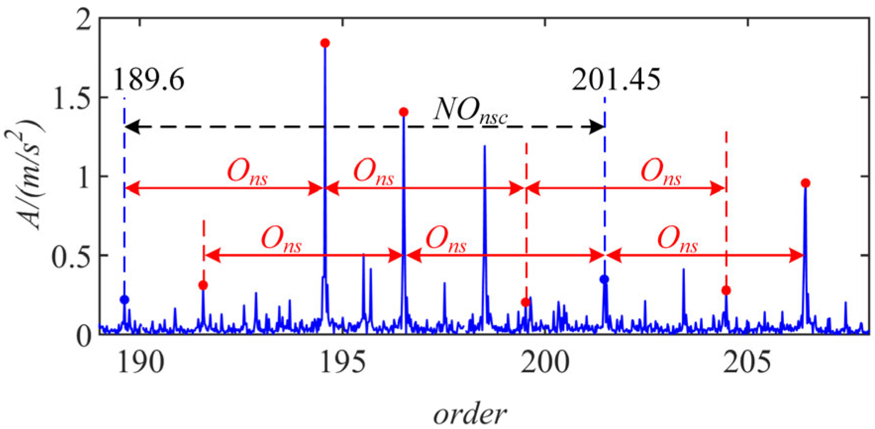
To further verify the effectiveness of the proposed vibration AM–FM models, the vibration AM models of localized faults of sun gears in Ref. [22] were used to predict the experimental vibration modulation components. The AM signal models focus on the modulation sidebands research within the resonance region. Therefore, the vibration AM models can only predict the modulation components within the resonance region, not the modulation sidebands around the harmonics of the meshing frequency. The predicted sidebands are marked with the red and blue dots in Figure 14, which indicates that some components even with large amplitudes cannot be predicted by the AM models. Hence, the comparison of Figure 12b and Figure 14 can further verify the superiority of the proposed models in terms of predicting the vibration modulation sidebands.
5. Conclusions
Improved vibration AM–FM signal models of localized faults of sun gears were developed, which can be used to identify the mechanisms of vibration modulation. The vibration signals of localized faults of sun gears include the AM–FM sidebands distributed around harmonics of the meshing frequency and the whole frequency range. The harmonics of the meshing frequency are modulated by the fault feature frequency to form fault modulation sidebands, which are further modulated via the rotational frequency of the carrier. There are two groups of modulation sidebands around the harmonics of the meshing frequency. The AM–FM features around the harmonics of the meshing frequency are similar to those caused by the distributed faults of sun gears. Additionally, the harmonics of the fault feature frequency distributed throughout the frequency range are modulated by the rotational frequency of the carrier, which are more dominant within the resonance ranges. Hence, the AM–FM features within the resonance range are better for the diagnosis of localized gear faults. The improved signal models can better explain the causes of the vibration AM–FM components, even with small amplitudes, induced by the localized faults of sun gears, which provide a theoretical basis for the detection of gear faults.
Author Contributions
Conceptualization, X.Y., G.Y., X.Z. and F.Y.; methodology, X.Y.; validation, X.Y., Q.Z. and C.D.; investigation, Q.Z. and C.D.; data curation, Z.C.; writing—original draft preparation, X.Y.; writing—review and editing, X.Y. and Z.C.; supervision, X.Z. and F.Y. All authors have read and agreed to the published version of the manuscript.
Funding
This work was partly supported by the National Natural Science Foundation of China (Nos. 52105087 and 52205087), the Guangzhou Science and Technology Program Projects (No. 2023A04J0280), and the Special Talents for Scientific Research Projects of Guangdong Polytechnic Normal University (No. 2022SDKYA019).
Data Availability Statement
The study did not report any data.
Conflicts of Interest
The authors declare no conflict of interest.
Appendix A
The transfer path function of w(t + tcq) of the qth meshing planet gear can be written as
where Wk is the Fourier coefficient of wk; J(∙) symbolizes the value of the Bessel function of the first kind; (sw, gw, …, hw) are the orders of the Bessel function.
where the Fourier coefficient Vo is 0.5; (sv, gv, …, hv) are the orders of the Bessel function.
References
- Chen, Z.; Liao, Y.; Li, J.; Huang, R.; Xu, L.; Jin, G.; Li, W. Multi-source Weighted Deep Transfer Network for Open-set Fault Diagnosis of Rotary Machinery. IEEE Trans. Cybern. 2022, 53, 1982–1993. [Google Scholar] [CrossRef] [PubMed]
- Chen, M.; Shao, H.; Dou, H.; Li, W.; Liu, B. Data augmentation and intelligent fault diagnosis of planetary gearbox using ILoFGAN under extremely limited samples. IEEE Trans. Reliab. 2022. [Google Scholar] [CrossRef]
- Li, Q.; Liang, S.Y. Weak fault detection for gearboxes using majorization–minimization and asymmetric convex penalty regularization. Symmetry 2018, 10, 243. [Google Scholar] [CrossRef]
- Cui, L.; Liu, T.; Huang, J.; Wang, H. Improvement on meshing stiffness algorithms of gear with peeling. Symmetry 2019, 11, 609. [Google Scholar] [CrossRef]
- Mohammed, S.A.; Ghazaly, N.M.; Abdo, J. Fault diagnosis of crack on gearbox using vibration-based approaches. Symmetry 2022, 14, 417. [Google Scholar] [CrossRef]
- Wang, T.; Han, Q.; Chu, F.; Feng, Z. Vibration based condition monitoring and fault diagnosis of wind turbine planetary gearbox: A review. Mech. Syst. Signal Process. 2019, 126, 662–685. [Google Scholar] [CrossRef]
- Zghal, B.; Graja, O.; Dziedziech, K.; Chaari, F.; Jablonski, A.; Barszcz, T.; Haddar, M. A new modeling of planetary gear set to predict modulation phenomenon. Mech. Syst. Signal Process. 2019, 127, 234–261. [Google Scholar] [CrossRef]
- Feki, N.; Karray, M.; Khabou, M.T.; Chaari, F.; Haddar, M. Frequency analysis of a two-stage planetary gearbox using two different methodologies. Comptes Rendus Méc. 2017, 345, 832–843. [Google Scholar] [CrossRef]
- McFadden, P.D.; Smith, J.D. An explanation for the asymmetry of the modulation sidebands about the tooth meshing frequency in epicyclic gear vibration. Proc. Inst. Mech. Eng. Part C J. Mech. Eng. Sci. 1985, 199, 65–70. [Google Scholar] [CrossRef]
- Inalpolat, M.; Kahraman, A. A theoretical and experimental investigation of modulation sidebands of planetary gear sets. J. Sound Vib. 2009, 323, 677–696. [Google Scholar] [CrossRef]
- Li, Y.; Ding, K.; He, G.; Yang, X. Vibration modulation sidebands mechanisms of equally-spaced planetary gear train with a floating sun gear. Mech. Syst. Signal Process. 2019, 129, 70–90. [Google Scholar] [CrossRef]
- He, G.; Ding, K.; Wu, X.; Yang, X. Dynamics modeling and vibration modulation signal analysis of wind turbine planetary gearbox with a floating sun gear. Renew. Energy 2019, 139, 718–729. [Google Scholar] [CrossRef]
- He, G.; Ding, K.; Li, W.; Li, Y. Frequency response model and mechanism for wind turbine planetary gear train vibration analysis. IET Renew. Power Gener. 2016, 11, 425–432. [Google Scholar] [CrossRef]
- Luo, Y.; Cui, L.; Ma, J. Effect of bolt constraint of ring gear on the vibration response of the planetary gearbox. Mech. Mach. Theory 2021, 159, 104260. [Google Scholar] [CrossRef]
- Yang, X.; Wang, L.; Ding, K.; Ding, X. Vibration AM-FM sidebands mechanism of planetary gearbox with tooth root cracked planet gear. Eng. Fail. Anal. 2022, 137, 106353. [Google Scholar] [CrossRef]
- Inalpolat, M.; Kahraman, A. A dynamic model to predict modulation sidebands of a planetary gear set having manufacturing errors. J. Sound Vib. 2017, 329, 371–393. [Google Scholar] [CrossRef]
- Liang, X.; Zuo, M.J.; Hoseini, M.R. Vibration signal modeling of a planetary gear set for tooth crack detection. Eng. Fail. Anal. 2015, 48, 185–200. [Google Scholar] [CrossRef]
- Lei, Y.; Liu, Z.; Lin, J.; Lu, F. Phenomenological models of vibration signals for condition monitoring and fault diagnosis of epicyclic gearboxes. J. Sound Vib. 2016, 369, 266–281. [Google Scholar] [CrossRef]
- Luo, Y.; Cui, L.; Zhang, J.; Ma, J. Vibration mechanism and improved phenomenological model of planetary gearbox with broken sun gear fault. Measurement 2021, 178, 109356. [Google Scholar] [CrossRef]
- Han, H.; Zhao, Z.; Tian, H.; Ma, H.; Yang, Y.; Li, X. Fault feature analysis of planetary gear set influenced by cracked gear tooth and pass effect of the planet gears. Eng. Fail. Anal. 2021, 121, 105162. [Google Scholar] [CrossRef]
- Yu, X.; Feng, Z.; Liang, M. Analytical vibration signal model and signature analysis in resonance region for planetary gearbox fault diagnosis. J. Sound Vib. 2021, 498, 115962. [Google Scholar] [CrossRef]
- Xu, L.; Ding, K.; He, G.; Li, Y.; Chen, Z. Resonance modulation vibration mechanism of equally-spaced planetary gearbox with a localized fault on sun gear. Mech. Syst. Signal Process. 2022, 166, 108450. [Google Scholar] [CrossRef]
- Yang, X.; Ding, K.; He, G.; Du, C.; Yu, W. Improved vibration AM-FM sideband phenomenon models of planetary gear set with distributed faults and fault-induced speed fluctuation. Mech. Mach. Theory 2023, 179, 105093. [Google Scholar] [CrossRef]
- Bachar, L.; Dadon, I.; Klein, R. The effects of the operating conditions and tooth fault on gear vibration signature. Mech. Syst. Signal Process. 2021, 154, 107508. [Google Scholar] [CrossRef]
- Randall, R.B. A new method of modeling gear faults. J. Mech. Des. 1982, 104, 259–267. [Google Scholar] [CrossRef]
- Sika, G.; Velex, P. Instability analysis in oscillators with velocity-modulated time-varying stiffness—Applications to gears submitted to engine speed fluctuations. J. Sound Vib. 2008, 318, 166–175. [Google Scholar] [CrossRef]
- Yang, X.; Ding, K.; He, G. Phenomenon-model-based AM-FM vibration mechanism of faulty spur gear. Mech. Syst. Signal Process. 2019, 134, 106366. [Google Scholar] [CrossRef]
Figure 1.
Single-stage planetary gearbox: (a) three main transfer paths; (b) meshing forces at time t.
Figure 1.
Single-stage planetary gearbox: (a) three main transfer paths; (b) meshing forces at time t.

Figure 2.
Rigid–flexible coupling dynamics model of fixed-shaft gearbox: (a) fixed-shaft gearbox; (b) broken tooth on driving gear.
Figure 2.
Rigid–flexible coupling dynamics model of fixed-shaft gearbox: (a) fixed-shaft gearbox; (b) broken tooth on driving gear.
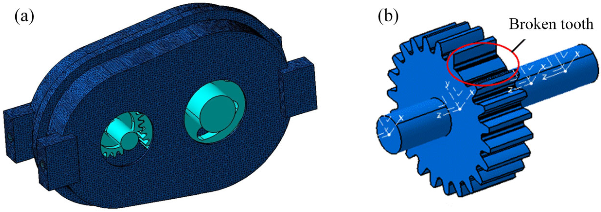
Figure 3.
Rotation speed of output shaft caused by a broken tooth on driving gear: (a) time-domain waveform; (b) amplitude spectrum.
Figure 3.
Rotation speed of output shaft caused by a broken tooth on driving gear: (a) time-domain waveform; (b) amplitude spectrum.
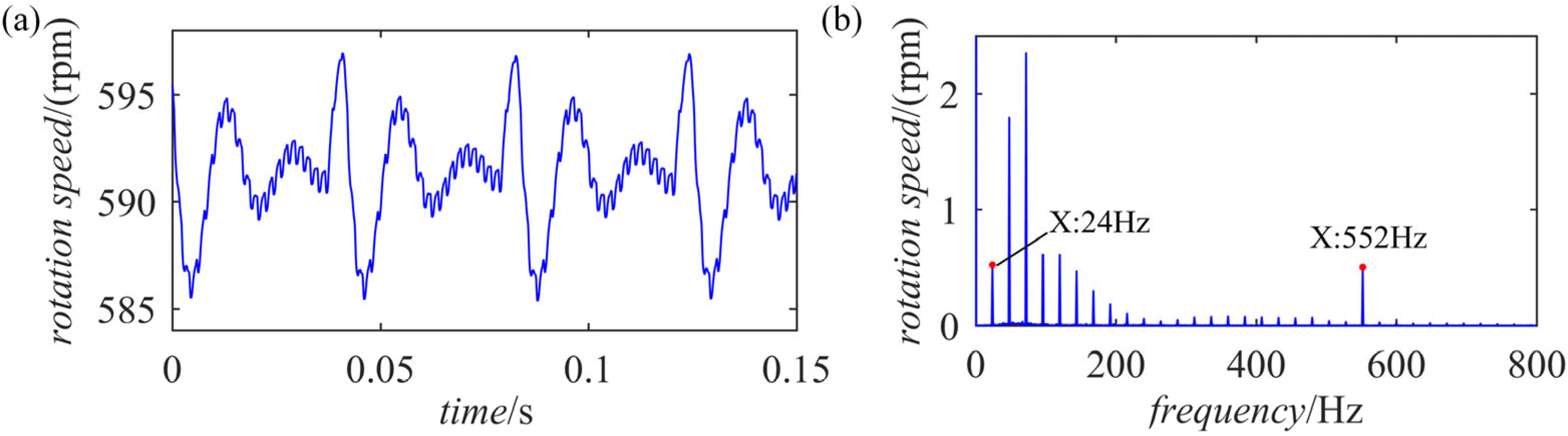
Figure 4.
Spectra of the factors affecting the vibration signal: (a) transfer path function; (b) projection function.
Figure 4.
Spectra of the factors affecting the vibration signal: (a) transfer path function; (b) projection function.
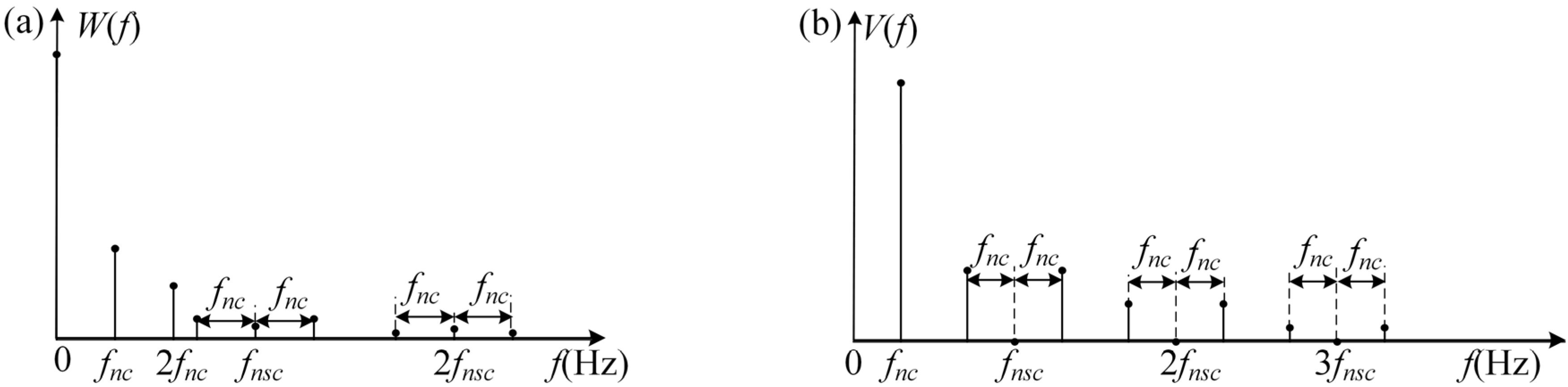
Figure 5.
Spectrum of the meshing force fsp: (a) AM–FM excitation around harmonics of the meshing frequency; (b) harmonics excitation of the fault feature frequency.
Figure 5.
Spectrum of the meshing force fsp: (a) AM–FM excitation around harmonics of the meshing frequency; (b) harmonics excitation of the fault feature frequency.
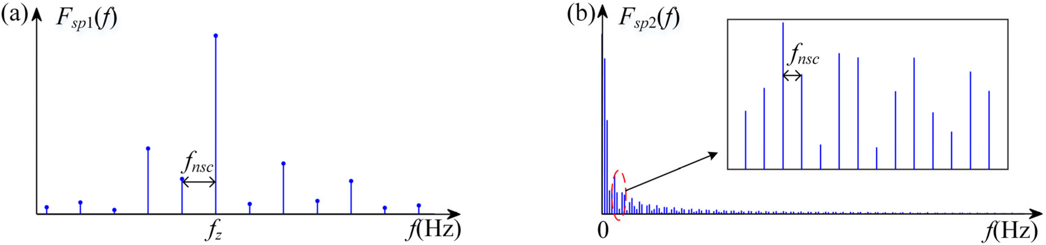
Figure 6.
Spectrum of vibration signal of path 1.

Figure 7.
Spectrum of vibration response .
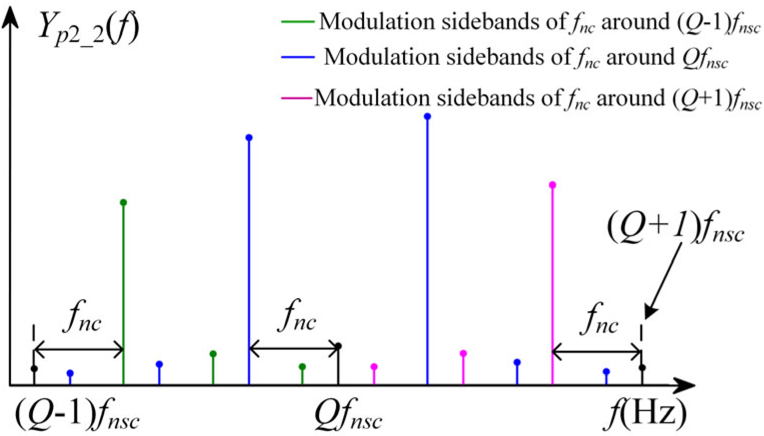
Figure 8.
Spectra of the vibration signals from path 3: (a) around the meshing frequency; (b) not around the harmonics of the meshing frequency.
Figure 8.
Spectra of the vibration signals from path 3: (a) around the meshing frequency; (b) not around the harmonics of the meshing frequency.
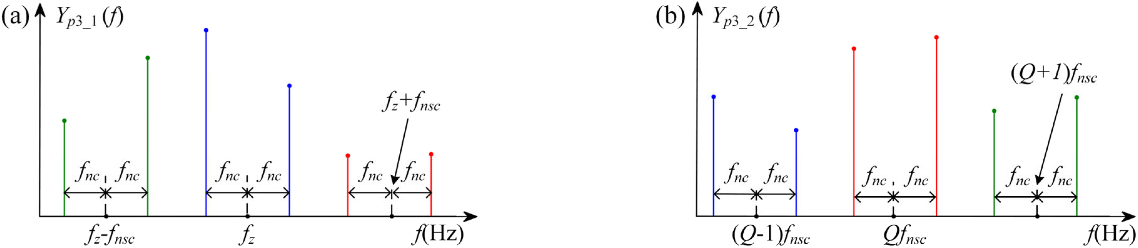
Figure 9.
Spectrum of the total vibration signal when zr/zs is not an integer: (a) around meshing frequency; (b) not around harmonics of the meshing frequency.
Figure 9.
Spectrum of the total vibration signal when zr/zs is not an integer: (a) around meshing frequency; (b) not around harmonics of the meshing frequency.
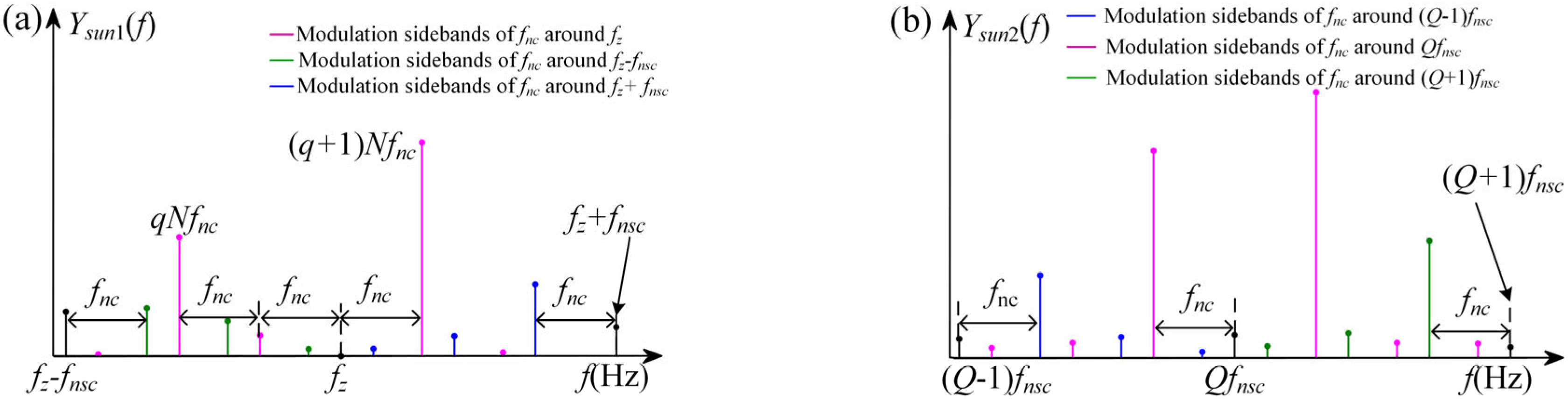
Figure 10.
Single stage planetary gear set: (a) test planetary gearbox; (b) structural sketch; (c) sun gear with broken tooth.
Figure 10.
Single stage planetary gear set: (a) test planetary gearbox; (b) structural sketch; (c) sun gear with broken tooth.
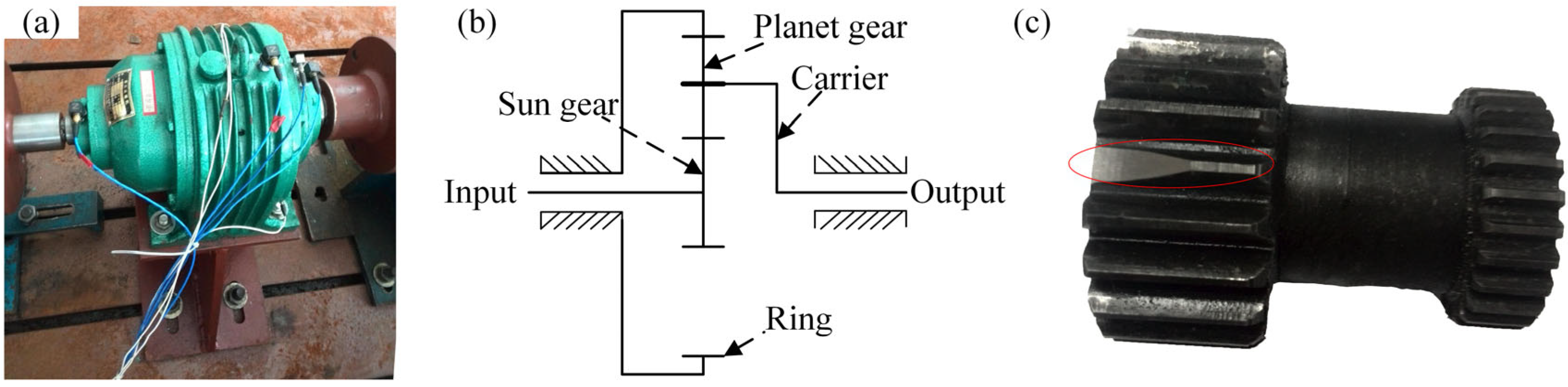
Figure 11.
Vibration signal: (a) time-domain waveform; (b) order spectrum.
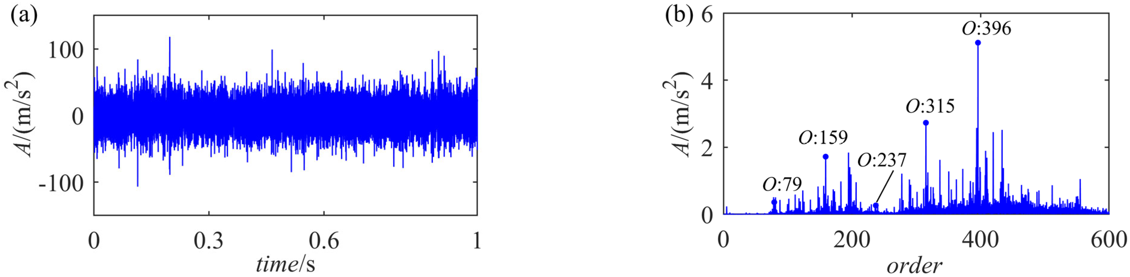
Figure 12.
Enlarged order spectrum: (a) around meshing order; (b) around the order of 200 (not around the harmonics of meshing order).
Figure 12.
Enlarged order spectrum: (a) around meshing order; (b) around the order of 200 (not around the harmonics of meshing order).
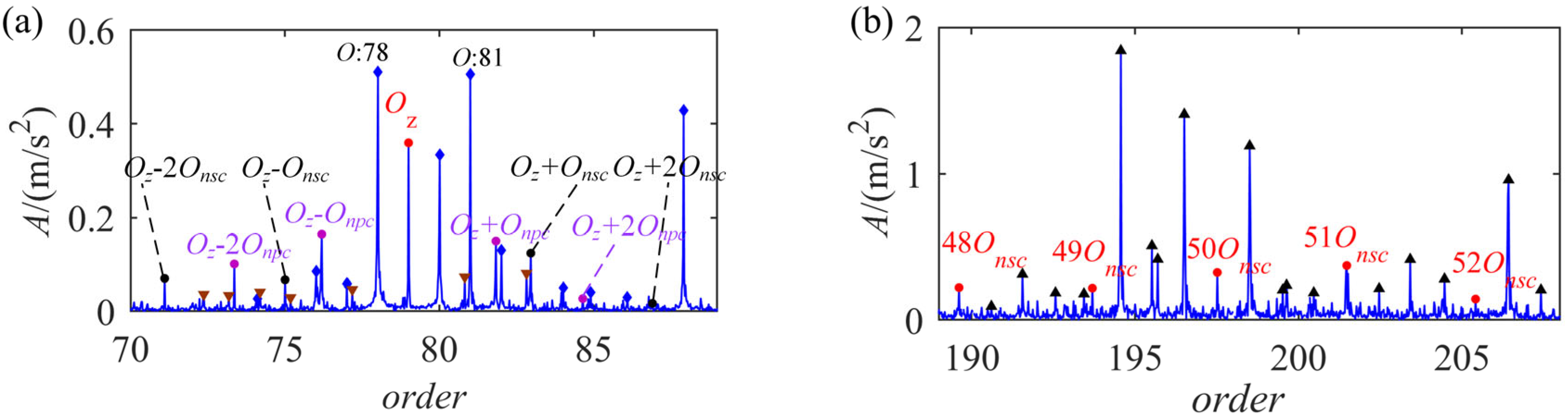
Figure 13.
Enlarged order spectrum around the second meshing order.

Figure 14.
Spectrum around the order of 200 predicted by the AM models.

Table 1.
Structure parameters and the fault feature order of single-stage planetary gearbox.
| Structural Parameters | Feature Orders | Order | |
|---|---|---|---|
| No. teeth of sun gear | 20 | Rotational order of carrier Onc | 1 |
| No. teeth of planet gear | 28 | Fault feature order of planet gear Onpc | 2.821 |
| No. teeth of ring gear | 79 | Meshing order Oz | 79 |
| Number of planets | 3 | Fault feature order of sun gear Onsc | 3.95 |
Disclaimer/Publisher’s Note: The statements, opinions and data contained in all publications are solely those of the individual author(s) and contributor(s) and not of MDPI and/or the editor(s). MDPI and/or the editor(s) disclaim responsibility for any injury to people or property resulting from any ideas, methods, instructions or products referred to in the content. |
© 2023 by the authors. Licensee MDPI, Basel, Switzerland. This article is an open access article distributed under the terms and conditions of the Creative Commons Attribution (CC BY) license (https://creativecommons.org/licenses/by/4.0/).
Share and Cite
MDPI and ACS Style
Yang, X.; Yang, G.; Zeng, Q.; Du, C.; Zeng, X.; Yu, F.; Chen, Z. Improved Vibration Signal Models of Localized Faults of Sun Gears to Predict Modulation. Symmetry 2023, 15, 1621. https://doi.org/10.3390/sym15091621
AMA Style
Yang X, Yang G, Zeng Q, Du C, Zeng X, Yu F, Chen Z. Improved Vibration Signal Models of Localized Faults of Sun Gears to Predict Modulation. Symmetry. 2023; 15(9):1621. https://doi.org/10.3390/sym15091621
Chicago/Turabian StyleYang, Xiaoqing, Gang Yang, Qiang Zeng, Canyi Du, Xiangkun Zeng, Feifei Yu, and Zhuyun Chen. 2023. "Improved Vibration Signal Models of Localized Faults of Sun Gears to Predict Modulation" Symmetry 15, no. 9: 1621. https://doi.org/10.3390/sym15091621
Note that from the first issue of 2016, this journal uses article numbers instead of page numbers. See further details here.