
Design of Axially Symmetric Fluid–Spring Vibration Absorber with Five DOFs Based on Orthogonal Experiment

1
Anhui Research Center for Generic Technologies in Robot Industry, Wuhu 241000, China
2
School of Mechanical Engineering, Anhui Polytechnic University, Wuhu 241000, China
3
Process Department, Fuyao Glass (Suzhou) Co., Ltd., Suzhou 215100, China
*
Author to whom correspondence should be addressed.
Symmetry 2023, 15(5), 980; https://doi.org/10.3390/sym15050980
Submission received: 9 February 2023
/
Revised: 15 April 2023
/
Accepted: 21 April 2023
/
Published: 25 April 2023
(This article belongs to the Special Issue Meta-Heuristics for Manufacturing Systems Optimization Ⅱ)
Abstract
:The strong and complex vibration from a manipulator for anchor drilling will damage the key components of the manipulator and produce noise at the same time. According to its vibration characteristics, a fluid–spring vibration absorption approach with five degrees of freedom (DOFs) is proposed, which has perfect symmetry, and a vibration absorber was designed with a symmetrical structure. Employing the generalization formula of the Bernoulli equation and dynamic equation, a fluid–spring coupling damping coefficient equation was constructed. Vibration transmissibility was used as the evaluation index of vibration absorption performance. The elastic coefficients of the tension spring and torsion spring, the area ratio of circular through-holes to the vibration-absorbing plate, and the radius of circular through-holes were the main independent factors influencing the damping coefficients. An orthogonal experiment with four factors and four levels was designed. Using FLUENT and SIMULATION to implement joint simulations, the distribution law of the flow fields and the damping coefficients of each approach were obtained, and then the best combination of factors was selected. Taking a manipulator used for anchor drilling in Huainan of China as a case study, using the designed fluid–spring vibration absorber, the vibration displacements in the five DOFs were reduced by 68.32%, 49.82%, 52.17%, 49.01%, and 57.09% respectively, indicating a good vibration absorption performance with symmetry about the -axis.
1. Introduction
There are mainly three vibration absorption modes: passive vibration absorption, active vibration absorption, and passive–active hybrid vibration absorption. The passive vibration absorption mechanism is directly connected with the vibration source, and the excitation of the vibration source drives the fluid in the vibration absorber through the firmware to form fluid vibration absorption [1]. Compared with other methods, passive vibration absorption does not need additional energy, which is a widely used vibration absorption method in mechanical engineering. The coupling vibration with multiple degrees of freedom (DOFs) is common in mechanical engineering, which may reduce the operation accuracy of equipment, and even cause irreversible damage, severely impacting normal utilization. Most of the existing vibration absorbers have good energy dissipation ability in the direction of partial translation or rotation, and cannot realize the vibration absorption in all DOFs. Those vibration absorbers with fewer DOFs cannot meet the requirements of smooth operation of underground mechanical equipment.
Hou et al. [2] established the finite element model of a viscous fluid vibration absorber using Carreau’s equation, discussed the nonlinear relationship between fluid viscosity and fluid shear rate, and tested the effect of geometry on absorbing output. Makris et al. [3] analyzed the damping medium, structure, and energy dissipation principle of a viscous damper, and deduced the theoretical calculation method of the damping force based on the Maxwell model. Narkhede et al. [4] analyzed the performance difference between the linear and nonlinear viscous dampers under shock excitation, obtained the additional damping ratio of the nonlinear fluid viscous damper under shock excitation using the energy dissipation method, and provided some design charts. Ou et al. [5,6] investigated the performances of different types of viscous fluids and established a vibration absorption force calculation model for viscous dampers through performance tests and theoretical studies on clearance and cylinder-with-holes viscous dampers. Hou et al. [7] proposed a new four-parameter damper model, which considers the fluid shear thinning and stiffness effects. The model proved that the main factors influencing the stiffness of the viscous damper were the viscosity of dimethyl silicone oil, excitation frequency, and velocity in the orifice. Niwa et al. [8] developed a high damping device with an additional damping ratio of 10–20%. The vibration response could be effectively reduced through analysis and verification. Fu et al. [9] designed a multistage passive damping device, which can change the damping coefficient according to the change of external excitation speed through mechanical means, and then output a large range of damping force. Ying et al. [10] designed a variable vibration-absorbing controller composed of a double-link hydraulic cylinder, bypass pipeline, and electro-hydraulic servo valve. Its damping coefficient is controlled by voltage and has the advantage of a wide output range, but it requires feedback control and energy supply, and the design is complex and not easy for later maintenance. Symans et al. [11] analyzed the elastic bulk modulus of the fluid medium and the performance of the designed semiactive shock absorber, but ignored the influence of the shear thinning characteristics of the medium. Hazaveh et al. [12] designed a shock absorber with annular clearance, whose damping varies with the displacement and direction of the piston, but the displacement of the annular plate in the shock absorber is only between the piston and the bolt. A tuned mass damper (TMD) is widely used as a vibration-controlled device to reduce the response of buildings under lateral loads such as seismic loads [13]. Hrovat et al. [14] proposed a semi-active TMD, which uses a small amount of external excitation to change the damping. This system is superior to the traditional passive control. Kamgar conducted extensive work on the optimal design [13], parameter optimization [15], improvement of performance level [16], and engineering applications [17,18] of TMD. However, its single-DOF attribute hinders its use for multi-DOF vibration reduction of anchor drills. Kurino et al. [19] developed a vibration absorber with a built-in controller that can change the number of damping holes in the shock absorber, thereby changing the damping coefficient of the shock absorber. Through dynamic performance testing, it was proven that the control effect of the shock absorber is superior to that of traditional viscous shock absorbers. Baldonedo [20] proposed the optimization of a vibration reduction system for a railway bridge to minimize the acceleration of the bridge and increase the vibration reduction system as best as possible, which finally presented good performance with the optimal parameters.
Aiming at the issue of multi-DOF coupling vibration, a fluid–spring vibration absorber is developed in this study, which has vibration absorption mechanisms in five DOFs. The fluid–spring coupling vibration absorption coefficients of the vibration absorber are derived using the generalization formula of the Bernoulli equation, and the vibration transmission rate is used as the evaluation index of vibration absorption performance. After the range of each parameter is determined, the structural parameters of multi-DOF fluid–spring vibration absorber with optimal vibration absorption performance are obtained using orthogonal experiments and joint simulations with FLUENT and SIMULATION.
2. Fluid–Spring Vibration Absorber
2.1. Mechanical Structure
An anchor drill in a coal mine support system will cause serious vibration, which will be transmitted to the pedestal from the roof bolter along a manipulator. In this study, a vibration absorber for manipulators used in anchor drilling, namely, a fluid–spring vibration absorber with five DOFs, is studied. As shown in Figure 1a, its structure has symmetry. A manipulator can be installed on the platform (17) of the vibration absorber. In the early stage, we studied the vibration mechanism of the drilling of a roof bolter for a mine support system [21], as well as the characteristics of vibration transmission along a manipulator [22], and obtained the 5-DOF vibration [22] to its pedestal, represented by the platform (17).
The fluid–spring vibration absorber with five DOFs is composed of box parts (see Figure 1b), spring vibration-absorbing parts (see Figure 1c), viscous parts with high vibration absorption (see Figure 1d), and dimethicone (4). The upper sieve plate (26), the middle sieve plate (12), and the lower sieve plate (8) of the viscous parts with high vibration absorption (3) are connected to the column (24) with fixed clamp assemblies (13 and 31) and screws, respectively. In addition, the upper sieve plate (26) of the viscous parts with high vibration absorption (3) is connected with the lower spherical pair (30) of the spring vibration-absorbing parts (2) by bolts. The axle sleeve (16) of the spring vibration-absorbing parts (2) is connected to the box parts (1) by the nut (15). The box parts (1) are filled with dimethicone (4).
As shown in Figure 1b, the pedestal (5) under the box parts (1) can be connected to a foundation with screws. An oil-out assembly (18) is arranged at the bottom of the box (20), and an observation device for oil level (19) is arranged at the middle and upper parts. The cover (14) is connected to the upper opening of the box (20) by screws. The vibration source is installed on the platform (17), which is connected to the upper end of the column (24) by screws. Most of the column (24) passes through the hole in the middle of the cover (14) and goes deep into the box (20). The diameter of the hole is much larger than that of the column (24) to avoid collision and friction when the column (24) vibrates. A sealing rubber (21) is arranged outside the middle hole of the cover (14), which is connected to the column (20) and the cover (14). In addition, all joints of the box parts (1) are sealed with elastic sealing rings to ensure that the overall box parts (1) are leak-free. The upper end of the column (24) is equipped with a torsion spring (23), one end of which is inserted with a retainer of torsion spring (22).
As shown in Figure 1c, the lower end of the tension springs (29) in the spring vibration-absorbing parts (2) is connected to the lower spherical pair (30), and the upper one is connected to the upper spherical pair (28). Owing to the universal rotation characteristics of the spherical pairs, the , , and DOFs are released to ensure that the vibration of these DOFs is reduced and dissipated in the dimethicone (4). The tension springs (29) only play the role of bearing weight in the vertical direction and reducing vibration in the DOF subordinately. The upper spherical pair (28) is connected to the attachment plate (27) with screws, and the suspension plate (27) is assembled with the axle sleeve (16) through the thrust ball bearing (25) to release the DOF.
As shown in Figure 1d, the outside sieve tube (7) and the inner sieve tube (9) of the viscous parts with high vibration absorption (3) are connected with the upper sieve plate (26), the middle sieve plate (12), and the lower sieve plate (8) using L-shaped connectors (6,10,11), and some vertical sieve plates (32) are uniformly distributed in them. There are a number of round holes in each sieve tube and sieve plate. In the process of vibration, dimethicone (4) passes through the holes and generates friction, which can dissipate energy and reduce vibration.
2.2. Vibration Transmission
The excitation is first transmitted from the platform (17) to the column (24), and then to the viscous parts with high vibration absorption (3). There is friction between the viscous parts with high vibration absorption (3) and the dimethicone (4), which converts the mechanical vibration energy in all directions into thermal energy, and achieves vibration absorption and energy consumption. Part of the -direction vibration is transmitted to the lower spherical pair (30) of the spring vibration-absorbing parts (2) via the viscous parts with high vibration absorption (3), and further damped by the tension springs (29) connected with it. There are corresponding vibration-absorbing devices and vibration absorption methods for each spatial DOF, and all five DOFs can be damped at the same time. In addition to vibration, the deadweight of the exciter and the viscous parts with high vibration absorption is also transmitted to the attachment plate (27) via the tension springs (29) and the upper spherical pair (28), and finally to the cover (14) of the box parts (1) via the thrust ball bearing (25) and the axle sleeve (16).
2.3. Vibration Absorption Method
- Vibration absorption in -direction: Under -directional vibration, there is relative motion between the dimethicone (4) in the box and the circular through-holes in the upper sieve plate (26), the middle sieve plate (12), and the lower sieve plate (8), which then generates fluid vibration absorption, and converts the mechanical vibration energy into thermal energy. In addition, the prestressed tension springs (29) can also reciprocate in the stretched balance position to assist reducing vibration while bearing weight.
- Vibration absorption in -direction: The excitation along the -direction is transmitted to the viscous parts with high vibration absorption (3); there is relative motion between the dimethicone (4) in the box and the circular through-holes in the outside sieve tube (7) and inner sieve tube (9), which converts the mechanical vibration energy into thermal energy to reduce the vibration along the .
- Vibration absorption in -direction: When the vibration in the -direction is transmitted, owing to the release of the -DOF by the spherical pairs (28,30), the viscous parts with high vibration absorption (3) vibrates around the in the box (20). There is mutual friction between the dimethicone (4) and the sieve plates distributed on the outside sieve tube (7), the inner sieve tube (9), the upper sieve plate (26), the middle sieve plate (12), and the lower sieve plate (8), which can consume energy.
- Vibration absorption in -direction: Due to the release of the -DOF by the spherical pairs (28,30), the viscous parts with high vibration absorption (3) vibrate around the in the box (20), and friction with the dimethicone (4) consumes energy.
- Vibration absorption in ()-direction: In a cylindrical coordinate system, the -direction and -direction are actually the same degrees of freedom; thus, this vibration absorber has five DOFs. The -direction and -direction are the same degreed of freedom. On the one hand, the vibration can be eliminated by the dimethicone (4) acting on the vertical sieve plate (32). On the other hand, the torsion spring (23) can also partially eliminate the vibration and prevent the platform (17) from drifting and rotating in the ()-direction.
3. Fluid Absorption Spring Coupling Damping Coefficient
3.1. Viscous Damping Coefficient of Vibration Absorber
Underlying assumptions: (1) the dimethyl silicone oil is an incompressible fluid, i.e., its density does not change with pressure; (2) steady flow, i.e., the flow field does not change with time; (3) motion along streamline; (4) dimethyl silicone oil is viscous; (5) fluid mass force is gravity only.
It is not difficult to find that assumptions (1) to (3) in this article strictly comply with the conditions of the Bernoulli equation, but (4) is not satisfied. Therefore, the generalization formula of the Bernoulli equation [23] (applicable to viscous fluid) is introduced in this study, as expressed in Equation (1).
where the head loss () is composed of the loss along the way () and the local loss (), as expressed in Equation (2).
Due to the vibration between the viscous fluid and the circular through-holes, there is a relative motion between them, the relative velocity is distributed unevenly, and the flow is turbulent. At this time, is generally 1.00 to 1.1 [24]; for convenience of calculation and reasonable simplification, order = 1. The average current velocity at the outlet of the circular through-hole is related to the pressure difference between and . To reasonably simplify the model, order = 0, and = 0 [24]. Therefore, Equation (1) can be simplified as follows:
Since = , according to the mass-conservation equation and Equation (3), the expression of mass flow () of a circular through-hole is as follows [25]:
According to the resistance formula of viscous fluid mechanics [23],
As , according to Equation (5), the viscous damping ratio is obtained as
Substituting Equations (2) and (4) into Equation (6) yields
The viscous damping coefficient of vibration absorber is as follows:
Substituting Equation (7) into Equation (8),
3.2. Damping Coefficient of Springs
3.2.1. Tension Springs
A fluid–spring vibration absorber with five degrees of freedom proposed in this study, including tension springs and a torsion spring. The elastic coefficient of the tension springs [26] is expressed as follows:
As the tension springs are submerged in the fluid, the force is as follows [23]:
Moreover, according to reference [27],
According to Equations (11) and (12),
In order to ensure the safe operation of the vibration absorber, it is necessary to ensure that the viscous parts do not collide with the platform (17) of the box, as follows:
where is distance between the lower sieve plate (8) and pedestal (5), expressed in mm.
3.2.2. Torsion Spring
The elastic coefficient of the torsion spring is expressed as follows:
The vibration absorption torque [28] on the torsion spring is as follows:
The fluid–torsion spring coupling damping coefficient can be expressed as follows:
4. Vibration Transmissibility
To evaluate the vibration absorption performance of the fluid–spring vibration absorber, a vibration transmissibility term [29] is introduced, which is defined as the ratio of the absolute amplitude of the source to the amplitude of excitation, as expressed in Equation (18).
5. Orthogonal Experiment
The main independent factors influencing the damping coefficients are as follows: (1) elastic coefficient of tension springs (); (2) elastic coefficient of torsion spring (); (3) area ratio of circular through-holes to vibration-absorbing plate (); (4) radius of circular through-holes (). Different parameter ranges and different combinations of the above factors can lead to different vibration absorption performances. If the conventional experimental method is adopted, the workload is huge, and substantial time is needed. An orthogonal experiment [30] can extract some typical experimental schemes from massive data to find the best combination of vibration absorption parameters.
The parameter ranges are mainly determined according to two points. Firstly, they are determined by the structure of the vibration absorber, i.e., the parameters must meet the requirements of the rationality and strength of its structure. For instance, as shown in Equation (8), it is necessary to ensure that the viscous parts do not collide with the platform (17) of the box, so as to determine the minimum elastic coefficient. Secondly, some feasible parameter ranges are obtained by single-factor experiments. A four-factor and four-level orthogonal experiment was designed, as shown in Table 1.
Four parameters (four levels) were selected for each of the four factors. Thus, a total of 256 (44) experiments would be required for full-scale experiments, but only 16 experiments were required according to the orthogonal experiment. The scheme is shown in Table 2.
5.1. Simulation Analysis on Fluid
ANSYS Fluent 2020 was used to analyze the flow field on the vibration of the viscous parts with high vibration absorption in the box relative to dimethicone.
5.1.1. Boundary Conditions
According to the experimental parameters designed in Table 1, the shock absorption model established in SolidWorks was imported into the “Space Claim” module in ANSYS. The space enclosed by the box was the fluid domain of the vibration absorber. The fluid domain [31] was extracted by Boolean and imported into the “Mesh” module, and then it was divided by a tetrahedral mesh.
During the operation of the vibration absorber, the fluid layers interfere with each other, and the intensity changes with the change in current velocity. In addition, there is momentum transfer between layers. The SIMPLE algorithm [31] is a kind of pressure-amending method. Its core idea is the process of “guess to amend”. The pressure field is calculated on the basis of mesh generation, so as to solve the momentum equation.
Settings of workbench: (1) the boundary in contact with dimethicone is set as a solid wall; (2) to improve the computational accuracy, the iterative time step is taken as 0.001 s; (3) the solver adopts SIMPLE algorithm; (4) k-epsilon realizable is adopted as the turbulence model; (5) the transient stress module is transient structural; (6) FLUENT is associated with transient structural, and the pressure and type variables interact with each other and iterate repeatedly.
5.1.2. Flow Field Analysis
According to the above steps and settings, the schemes in Table 2 were simulated in turn. The pressure contours of the circular through-holes on 16 groups were obtained, as shown in Figure 2. The distribution of pressure is shown in the pressure contour of each group, distinguished by different colors. As shown in Figure 2a, the pressure of the first group varied from −3.635 × 10⁴ Pa to 4.673 × 10⁴ Pa. The velocity contours of the circular through-holes on 16 groups are shown in Figure 3. The distribution of velocity is shown in the velocity contour of each group, distinguished by different colors. As shown in Figure 3a, the velocity of the first group varied from 1.74 m/s to 19.28 m/s.
Using the damping coefficient of the circular through-hole in fluid, Equation (6), the data of all groups and corresponding damping coefficients are summarized in Table 3.
It is well known that a greater denotes better energy dissipation performance [32]. It can be seen from Table 3 that the viscous coefficient of the vibration absorber of the seventh group was the largest, reaching 448.77 (N·s·mm−1); thus, its damping effect was best. Its structural parameters were as follows: = 33%, = 13 mm.
5.2. Dynamics Simulation on Springs
The fluid–spring coupling vibration absorption was simulated using Solidworks SIMULATION 2021 [33]. As shown in Figure 1, nine tension springs were connected to the fluid domain; the lower end of the tension springs was fixed, and the upper end was mobile. To raise the computational accuracy, curvature-based mesh generation was adopted. The simulations were carried out in turn according to Table 2 and Table 3. The displacement contours of fluid–tension spring coupled vibration are shown in Figure 4; the maximum values of vibration displacement of each group are listed in the first column of Table 4, ranging between 10.64 mm and 29.05 mm. Moreover, the displacement contours of fluid–torsion spring coupled vibration are shown in Figure 5; the maximum values of vibration displacement of each group are listed in the second column of Table 4, ranging between 3.01 mm and 8.25mm.
Adopting the representations of the spring coefficients of the tension springs and the torsion spring (Equations (14) and (17), respectively), some performance parameters such as , , , and of each group were calculated, as summarized in Table 5. It can be seen that the fluid–spring coupling damping coefficient () of the 10th group was the largest, reaching 432.70 (N·s·mm−1). Its parameters were as follows: = 37%, = 11 mm, = 41 N·mm−1, and = 1111 g·mm·°−1.
5.3. Fluid–Spring Coupling Vibration Absorption Response
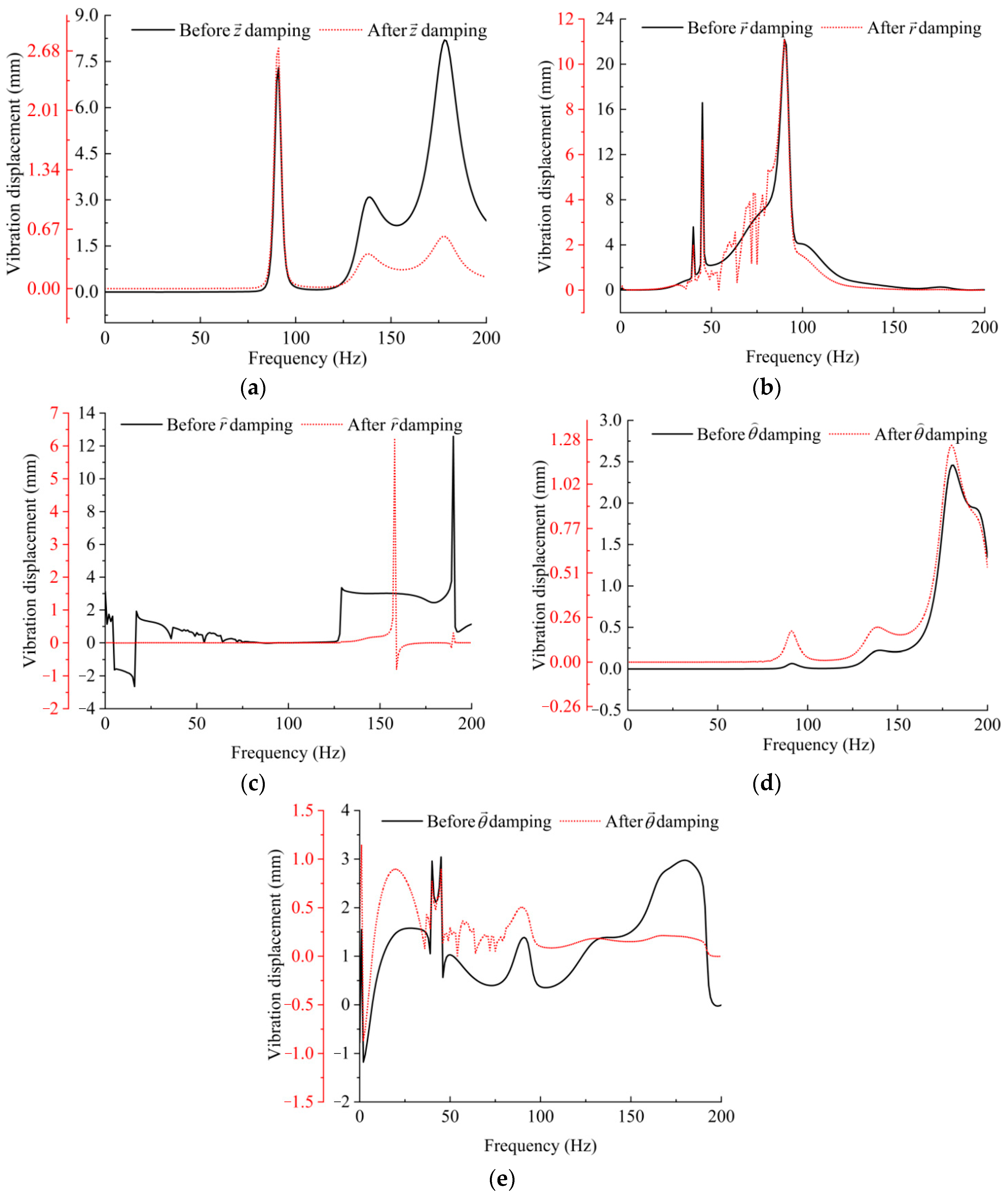
The total mass () of the developed vibration absorber was 130 kg, in which the density of the dimethicone was 889 kg·m−3 [34]; the solid material was AISI 1020, with a density of 7900 kg·m−3 [35]. The vibration absorption performance is positively correlated with the damping coefficient; therefore, the 10th group in Table 5 was adopted, in which = 432.70 (N·s·mm−1). The developed vibration absorber can be used for reducing the vibration of manipulator for anchor drilling in Huainan, China; the excitation frequency from a manipulator for anchor drilling is 0–200 Hz [21,22]. A vibration transmissibility of 0–200 Hz and step size of = 1 Hz were obtained by MATLAB 2019 according to Equation (18). The difference in vibration displacement before and after vibration absorption of the platform (17) of the manipulator for anchor drilling is shown in Figure 6.
As shown in Figure 6, when there was no vibration absorber, the vibration displacements in the five DOFs of the platform (17) were as follows: = 8.46 mm, = 22.78 mm, = 13.57 mm, = 2.51 mm, and = 2.96 mm. When there was a vibration absorber, the vibration displacements were as follows: = 2.68 mm, = 11.43 mm, = 6.49 mm, = 1.28 mm, and = 1.27 mm. Those vibration displacements were symmetric along the z-axis. The vibration displacements in the five DOFs were reduced by 68.32%, 49.82%, 52.17%, 49.01%, and 57.09%, respectively, showing that a good vibration absorption performance was obtained successfully.
6. Conclusions
A fluid–spring vibration absorber with five DOFs was developed successfully; its mechanical structure, vibration transmission, and vibration absorption method were described. A fluid–spring coupling damping coefficient equation was constructed, and the vibration transmissibility was taken as the evaluation index of vibration absorption performance. An orthogonal experiment with four factors and four levels was designed. Adopting FLUENT and SIMULATION to implement joint simulations, the fluid–spring coupling damping coefficients of 16 groups in orthogonal experiments were obtained, and some conclusions could be drawn. It can be seen from the velocity contours that there was turbulence in the vibration absorber under the excitation of external load. Thus, the distribution law of pressure and velocity in the fluid domain of the vibration absorber was obtained. The best combination of various factors and levels was obtained through the orthogonal experiment, and then the maximum output vibration absorption was obtained. The fluid–spring coupling damping coefficient of the vibration absorber reached a maximum of 432.70 N·s·mm−1. Its parameters were as follows: = 37%, = 11 mm, = 41 N·mm−1, and = 1111 g·mm·°−1. Taking a manipulator used for anchor drilling in Huainan of China as a case study, adopting the designed fluid–spring vibration absorber, the vibration displacements in the five DOFs were reduced by 68.32%, 49.82%, 52.17%, 49.01%, and 57.09% respectively, revealing that a good vibration absorption performance was obtained successfully.
The designed shock absorber and its absorption performances were symmetrical along the z-axis, which could reduce the vibration along the five DOFs; the orthogonal experiment was used to optimize its multifactor and multilevel combination parameters, minimizing the number of experiments and shortening the design period. However, the influence of fluid temperature on the damping coefficients was not considered in the orthogonal experiment, and the stiffness coefficient and viscous damping coefficient were not further optimized, which will be addressed in future work.
Author Contributions
Conceptualization, Y.L. and L.M.; methodology, Z.F. and Y.L.; software, L.M.; validation, P.W., Z.W. and L.M.; formal analysis, W.T.; investigation, Z.W.; resources, Y.L.; data curation, L.M.; writing—original draft preparation, Z.F.; writing—review and editing, W.T.; visualization, L.M.; supervision, Z.W.; project administration, Y.L.; funding acquisition, Y.L. All authors have read and agreed to the published version of the manuscript.
Funding
This study was supported in part by the Practice and Innovation Project of Anhui Polytechnic University for postgraduates under Grant No. 2, and by the Natural Science Research Project of Higher Education of Anhui Province of China under Grant No. YJS20210446.
Institutional Review Board Statement
Not applicable.
Informed Consent Statement
Not applicable.
Data Availability Statement
Not applicable.
Conflicts of Interest
The authors declare no conflict of interest.
Nomenclature
| -axis | |
| translational DOF along the -axis | |
| rotational DOF along the -axis | |
| polar angle (rad) | |
| translational DOF along | |
| rotational DOF along | |
| polar diameter (m) | |
| translational DOF along | |
| rotational DOF along | |
| pressure (Pa) | |
| inlet pressure of circular through-hole (Pa) | |
| outlet pressure of circular through-hole (Pa) | |
| gravitational acceleration (m/s2) | |
| current velocity (m·s−1) | |
| average current velocity at inlet of circular through-hole (m·s−1) | |
| average current velocity at outlet of circular through-hole (m·s−1) | |
| amending factors of kinetic energy for inlet | |
| amending factors of kinetic energy for outlet | |
| head loss (Pa) | |
| loss along the way (Pa) | |
| local loss (Pa) | |
| damping coefficient along the way | |
| thickness of vibration absorbing plate (mm) | |
| average current velocity of effective section (m·s−1) | |
| radius of circular through-hole (mm) | |
| excitation frequency (Hz) | |
| local resistance coefficient | |
| damping ratio of vibration system | |
| density (kg·m−3) | |
| mass flow | |
| area of circular through-hole (mm2) | |
| area ratio of circular circular through-holes to vibration-absorbing plate | |
| viscous damping ratio | |
| fluid–spring coupling damping coefficient (N·s·mm−1) | |
| viscous damping coefficient (N·s·mm−1) | |
| fluid–tension spring coupling damping coefficient (N·s·m−1) | |
| fluid–torsion spring coupling damping coefficient (N·s·mm−1) | |
| number of circular circular through-holes | |
| elastic coefficient of the tension spring (N·mm−1) | |
| rigidity modulus (N·mm−2) | |
| diameter of steel wire (mm) | |
| diameter of spring pitch (mm) | |
| Young’s modulus (Pa) | |
| number of active coils | |
| displacement of tension spring (mm) | |
| displacement of torsion spring (mm) | |
| damping force (N) | |
| force on springs (N) | |
| distance between the lower sieve plate (8) and pedestal (5) (mm) | |
| mass of attachment block of springs (kg) | |
| viscous vibration absorption constant | |
| speed of attachment block of springs (mm·s−1) | |
| acceleration of attachment block of springs (mm·s−2) | |
| elastic coefficient of torsion spring (g·mm·°−1) | |
| elastic coefficient of tension spring (N·mm−1) | |
| elastic modulus (N·mm−2) | |
| angular velocity (rad·s−1) | |
| vibration absorption torque (N·mm) | |
| diameter of axle sleeve (mm) | |
| diameter of column (mm) | |
| vibration transmissibility | |
| absolute amplitude (mm) | |
| amplitude of excitation(mm) | |
| frequency ratio, | |
| vibration frequency (Hz) | |
| natural frequency (Hz), | |
| vibration absorption ratio, | |
| system quality (kg) | |
| system stiffness (N·mm) |
References
- Huang, Z.X.; Yang, D.Q.; Jiang, S.P.; Zhang, Z.Y. Design and experiment of a mini isolator with fluid damping. J. Vib. Shock 2021, 40, 180–185. (In Chinese) [Google Scholar]
- Hou, C.Y.; Hsu, D.S.; Lee, Y.F.; Chen, H.Y.; Lee, J.D. Shear-thinning effects in annular-orifice viscous fluid dampers. J. Chin. Inst. Eng. 2007, 30, 275–287. [Google Scholar] [CrossRef]
- Makris, N.; Constantinou, M.C.; Reinhorn, A.M. Viscous Dampers: Testing, Modeling and Application in Vibration and Seismic Isolation; Buffalo: New York, NY, USA, 1990; pp. 67–78. [Google Scholar]
- Narkhede, D.I.; Sinha, R. Behavior of nonlinear fluid viscous dampers for control of shock vibrations. J. Sound Vib. 2014, 333, 80–98. [Google Scholar] [CrossRef]
- Ou, J.P.; Ding, J.H. Theory and performance experiment of viscous damper of clearance hydro cylinder. Earthq. Eng. Eng. Vib. 1999, 19, 82–89. [Google Scholar]
- Ding, J.H.; Ou, J.P. Theoretical study and performance experiment for cylinder with holes viscous damper. World Inf. Earthq. Eng 2001, 17, 30–35. [Google Scholar]
- Hou, C.Y. Behavior explanation and a new model for nonlinear viscous fluid dampers with a simple annular orifice. Arch. Appl. Mech. 2012, 82, 1–12. [Google Scholar] [CrossRef]
- Niwa, N.; Kobori, T.; Takahashi, M.; Hatada, T.; Kurino, H.; Tagami, J. Passive seismic response controlled high-rise building with high damping device. Earthq. Eng. Struct. Dyn. 1995, 24, 655–671. [Google Scholar] [CrossRef]
- Fu, W.Q.; Mao, L.I.; Tong, L.I.; Zhang, C.W. Design, performance test and structural wind vibration control analysis of multi-stage variable damping device. Eng. Mech. 2020, 37, 225–233. (In Chinese) [Google Scholar] [CrossRef]
- Ying, L.; Weiming, Y.; Jinbao, J. Performance analysis on viscous damper of variable clearance. Technol. Earthq. Disaster Prev. 2006, 1, 53–162. [Google Scholar]
- Symans, M.D.; Constantinou, M.C. Semi-active control systems for seismic protection of structures: A state-of-the-art review. Eng. Struct. 1999, 21, 469–487. [Google Scholar] [CrossRef]
- Hazaveh, N.K.; Rodgers, G.W.; Chase, J.G.; Pampanin, S. Experimental test and validation of a direction-and displacement-dependent viscous damper. J. Eng. Mech. 2017, 143, 04017132. [Google Scholar] [CrossRef]
- Khatibinia, M.; Gholami, H.; Kamgar, R. Optimal design of tuned mass dampers subjected to continuous stationary critical excitation. Int. J. Dyn. Control 2018, 6, 1094–1104. [Google Scholar] [CrossRef]
- Hrovat, D.; Barak, P.; Rabins, M. Semi-active versus passive or active tuned mass dampers for structural control. J. Eng. Mech. 1983, 109, 691–705. [Google Scholar] [CrossRef]
- Kamgar, R.; Samea, P.; Khatibinia, M. Optimizing parameters of tuned mass damper subjected to critical earthquake. Struct. Des. Tall Spec. Build. 2018, 27, e1460. [Google Scholar] [CrossRef]
- Dadkhah, M.; Kamgar, R.; Heidarzadeh, H.; Jakubczyk-Gałczyńska, A.; Jankowski, R. Improvement of performance level of steel moment-resisting frames using tuned mass damper system. Appl. Sci. 2020, 10, 3403. [Google Scholar] [CrossRef]
- Salimi, M.; Kamgar, R.; Heidarzadeh, H. An evaluation of the advantages of friction TMD over conventional TMD. Innov. Infrastruct. Solut. 2021, 6, 95. [Google Scholar] [CrossRef]
- Kamgar, R.; Gholami, F.; Sanayei, H.R.Z.; Heidarzadeh, H. Modified tuned liquid dampers for seismic protection of buildings considering soil–structure interaction effects. Iran. J. Sci. Technol. Trans. Civ. Eng. 2020, 44, 339–354. [Google Scholar] [CrossRef]
- Kurino, H.; Tagami, J.; Shimizu, K.; Kobori, T. Switching oil damper with built-in controller for structural control. J. Struct. Eng. 2003, 129, 895–904. [Google Scholar] [CrossRef]
- Baldonedo, J.; López-Campos, J.A.; López, M.; Casarejos, E.; Fernández, J.R. Optimization of the Auxiliary-Beam System in Railway Bridge Vibration Mitigation Using FEM Simulation and Genetic Algorithms. Symmetry 2019, 11, 1089. [Google Scholar] [CrossRef]
- Liu, Y.Y.; Ma, L.T.; Li, R.J.; Chen, B.; Guo, Y.C. Analysis of the Longitudinal-Bending-Torsional Coupled Vibration Mechanism of the Drilling of a Roof Bolter for Mine Support System. Math. Probl. Eng. 2022, 2022, 4279959. [Google Scholar] [CrossRef]
- Liu, Y.Y.; Ma, L.T.; Yang, S.Y.; Yuan, L.; Chen, B. MTPA-and MSM-based Vibration Transfer of 6-DOF Manipulator for Anchor Drilling. Stroj. Vestn.-J. Mech. Eng. 2022, 68, 529–541. [Google Scholar] [CrossRef]
- Kazemi, A.; Padgett, D.A.; Callahan, S.; Stoddard, M.; Amini, A.A. Relative pressure estimation from 4D flow MRI using generalized Bernoulli equation in a phantom model of arterial stenosis. Magn. Reson. Mater. Physics. Biol. Med. 2022, 1–16. [Google Scholar] [CrossRef]
- Pope, S.B. Turbulent Flows; Cambridge University Press: Cambridge, UK, 2000; pp. 359–385. [Google Scholar]
- Wu, Y.; Guo, Y.S.; Hong, M. Performance simulation and parameter analysis of viscous fluid damper based on orthogonal design. Chin. J. Ship Res. 2021, 16, 164–169. (In Chinese) [Google Scholar] [CrossRef]
- Jee, J.; Kim, C.; Kim, Y. Design improvement of a viscous-spring damper for controlling torsional vibration in a propulsion shafting system with an engine acceleration problem. J. Mar. Sci. Eng. 2020, 8, 428. [Google Scholar] [CrossRef]
- Wu, X.J.; Zhu, S.J. Parameters optimization of shock isolator composed of ordinary components. J. Vib. Shock 2005, 5, 74–76. [Google Scholar]
- Dütsch, H.; Durst, F.; Melling, A. Fluid–structure interactions of a torsion spring pendulum at large initial amplitudes. J. Fluid Mech. 2002, 471, 219–238. [Google Scholar] [CrossRef]
- Nakamura, Y.; Nakayama, M.; Masuda, K.; Tanaka, K.; Yasuda, M.; Fujita, T. Development of active 6-DOF micro vibration control system using giant magneto strictive actuator. Smart Struct. Mater. Smart Syst. Bridges Struct. Highways. Spie 1999, 3671, 229–240. [Google Scholar] [CrossRef]
- Wei, Y.H.; Wu, R.X.; Zou, L.M.; Liu, N.N.; Xue, X. Vacuum Brazing Effect on the Interlayer Failure Behaviors of Elastic-Porous Sandwich Structure with Entangled Metallic Wire Mesh. Symmetry 2022, 14, 977. [Google Scholar] [CrossRef]
- Matsson, J.E. An Introduction to ANSYS Fluent; SDC Publications: Mission, KS, USA, 2021. [Google Scholar]
- Fu, L.; Guo, T.; Li, G. Investigation on damping performance of new type oscillator-liquid combined damper. Int. J. Mech. Sci. 2018, 135, 53–62. [Google Scholar] [CrossRef]
- Kurowski, P. Vibration Analysis with SolidWorks Simulation; SDC Publications: Mission, KS, USA, 2016. [Google Scholar]
- Sun, T.; Wang, H.; Zong, Z.; Zhang, G.Y.; Wang, A.; Xu, C. Splash formation and cavity dynamics of sphere entry through a viscous liquid resting on the water. Aip Adv. 2019, 9, 075211. [Google Scholar] [CrossRef]
- Supriyatna, Y.I.; Noviyana, R.; Suka, E.G.; Kambuna, B.N.H.; Sumardi, S. Influence of current density in Cu-Mn electroplating of AISI 1020 steel corrosion rate. Mater. Today Proc. 2021, 44, 3289–3295. [Google Scholar] [CrossRef]
Figure 1.
Fluid–spring vibration absorber with five DOFs: (a) profile; (b) box parts; (c) spring vibration-absorbing parts; (d) viscous parts with high vibration absorption. 1—box parts; 2—spring vibration-absorbing parts; 3—viscous parts with high vibration absorption; 4—dimethicone; 5—pedestal; 6—L-shaped connector; 7—outside sieve tube; 8—lower sieve plate; 9—inner sieve tube; 10—L-shaped connector; 11—L-shaped connector; 12—middle sieve plate; 13—clamp assembly; 14—cover; 15—nut; 16—axle sleeve; 17—platform; 18—oil-out assembly; 19—observation device for oil level; 20—box; 21—sealing rubber; 22—retainer of torsion spring; 23—torsion spring; 24—column; 25—thrust ball bearing; 26—upper sieve plate; 27—attachment plate; 28—upper spherical pair; 29—tension springs; 30—lower spherical pair; 31—clamp assembly; 32—vertical sieve plate.

Figure 2.
Pressure contours: (a) first group; (b) second group; (c) third group; (d) fourth group; (e) fifth group; (f) sixth group; (g) seventh group; (h) eighth group; (i) ninth group; (j) 10th group; (k) 11th group; (l) 12th group; (m) 13th group; (n) 14th group; (o) 15th group; (p) 16th group.
Figure 2.
Pressure contours: (a) first group; (b) second group; (c) third group; (d) fourth group; (e) fifth group; (f) sixth group; (g) seventh group; (h) eighth group; (i) ninth group; (j) 10th group; (k) 11th group; (l) 12th group; (m) 13th group; (n) 14th group; (o) 15th group; (p) 16th group.
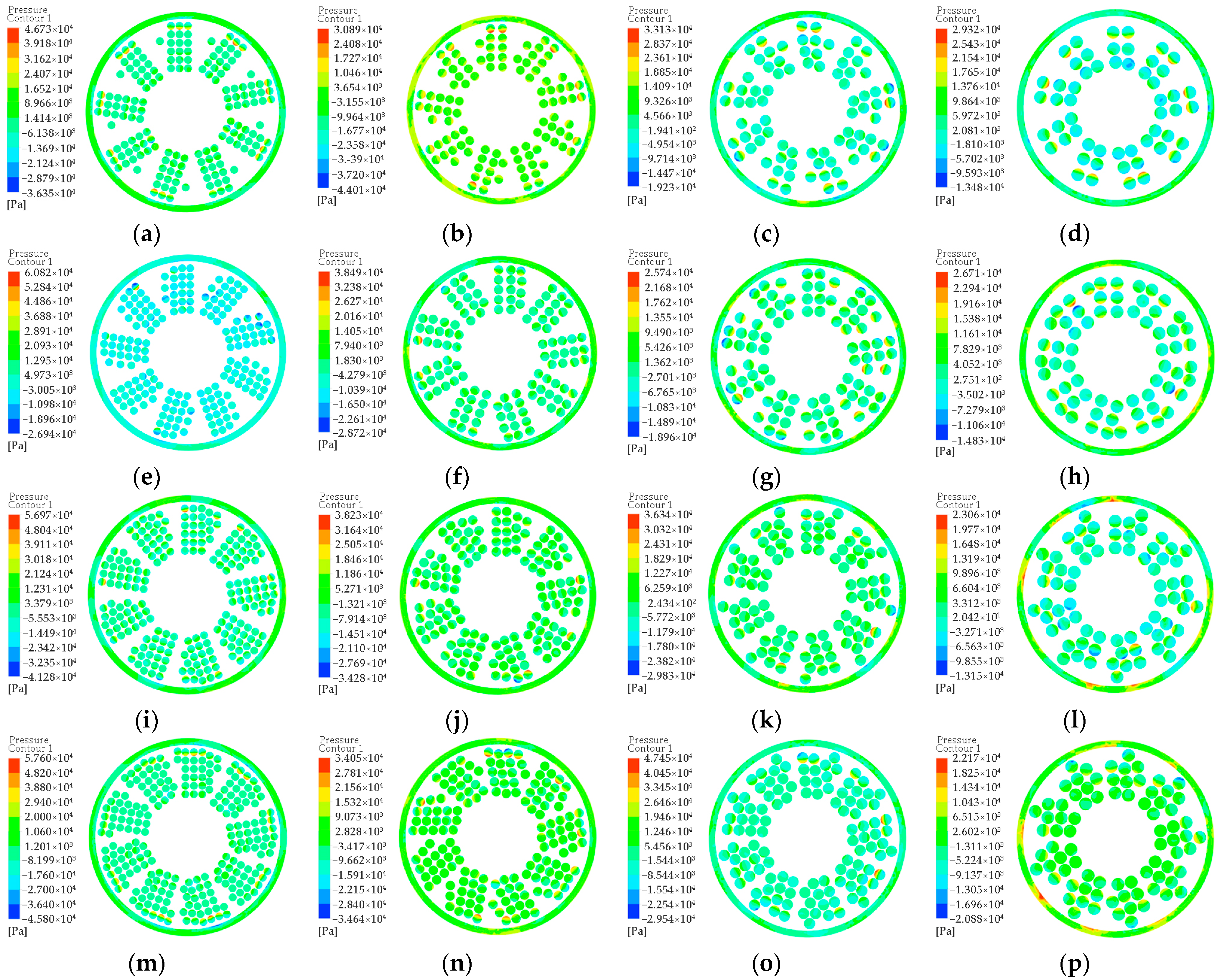
Figure 3.
Velocity contours: (a) first group; (b) second group; (c) third group; (d) fourth group; (e) fifth group; (f) sixth group; (g) seventh group; (h) eighth group; (i) ninth group; (j) 10th group; (k) 11th group; (l) 12th group; (m) 13th group; (n) 14th group; (o) 15th group; (p) 16th group.
Figure 3.
Velocity contours: (a) first group; (b) second group; (c) third group; (d) fourth group; (e) fifth group; (f) sixth group; (g) seventh group; (h) eighth group; (i) ninth group; (j) 10th group; (k) 11th group; (l) 12th group; (m) 13th group; (n) 14th group; (o) 15th group; (p) 16th group.
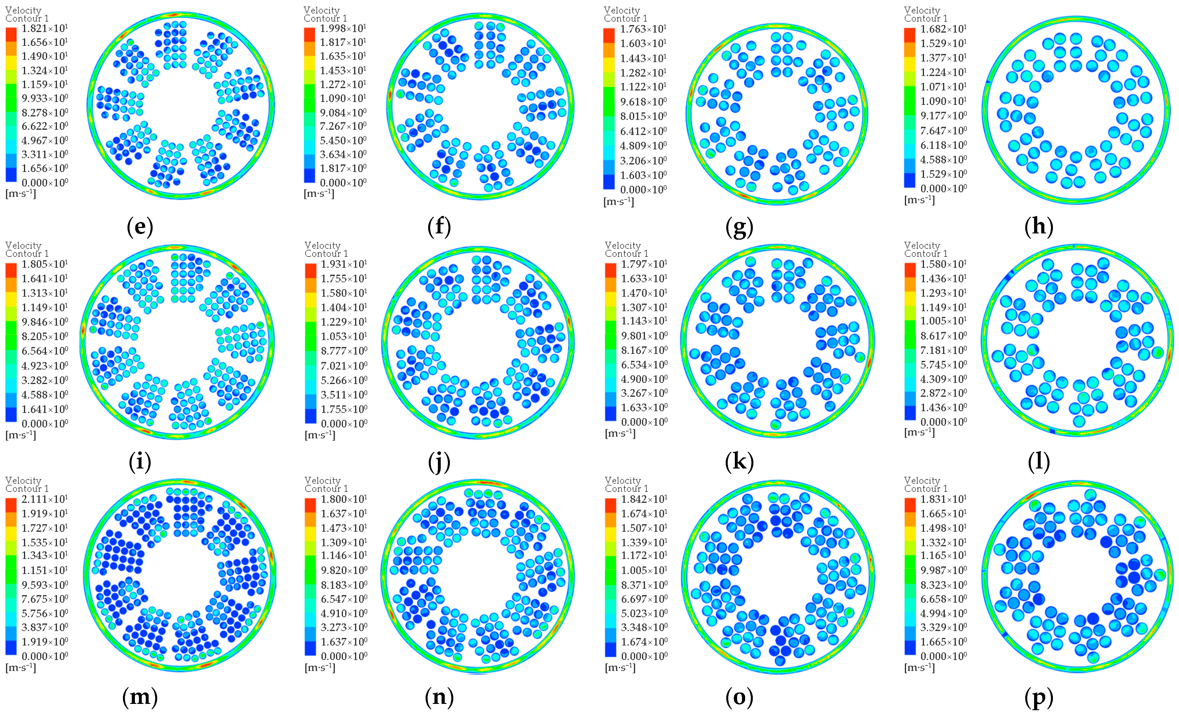
Figure 4.
Displacement contours of fluid–tension spring coupled vibration.
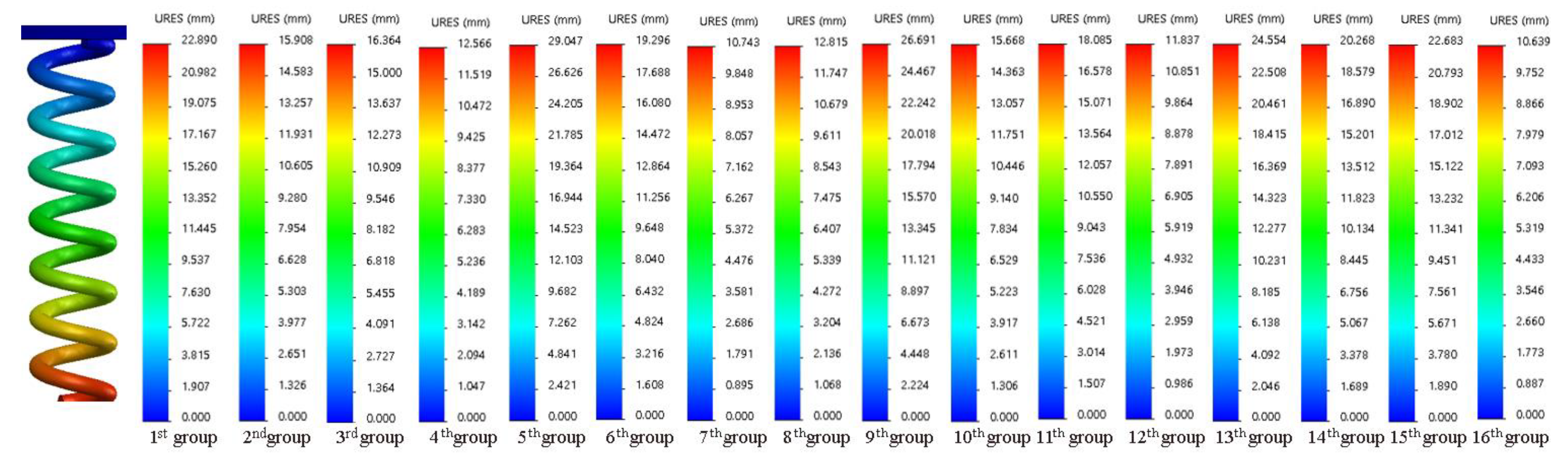
Figure 5.
Displacement contours of fluid–torsion spring coupled vibration.
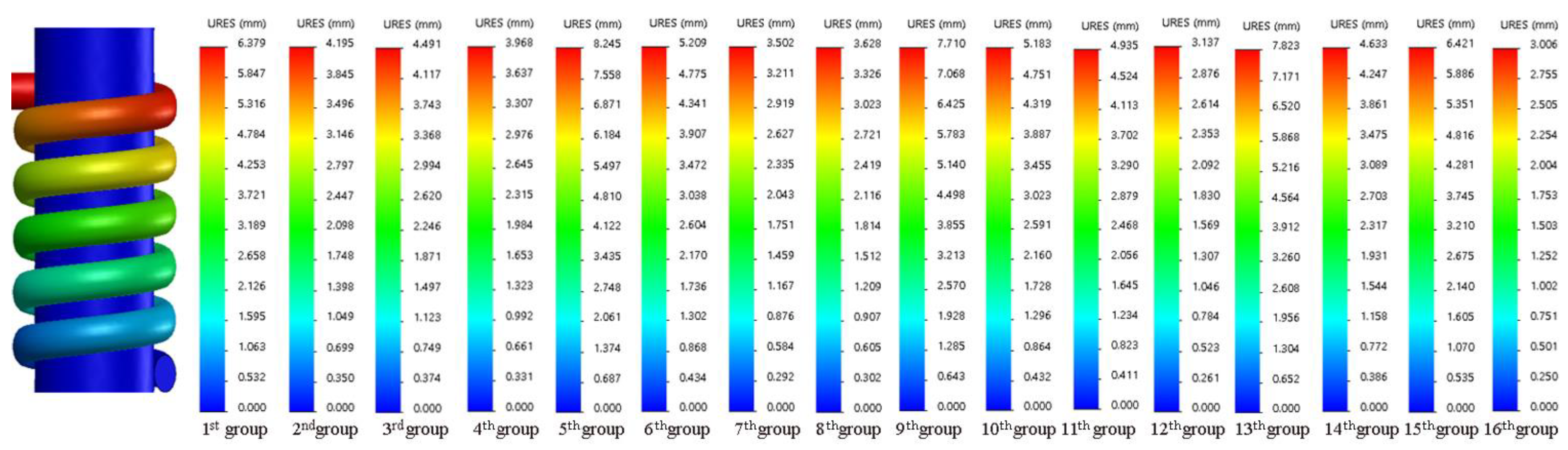
Figure 6.
Comparison of vibration displacement before and after vibration absorption: (a) -DOF; (b) -DOF; (c) -DOF; (d) -DOF; (e) -DOF.
Figure 6.
Comparison of vibration displacement before and after vibration absorption: (a) -DOF; (b) -DOF; (c) -DOF; (d) -DOF; (e) -DOF.

Table 1.
Factors and levels graph.
| Levels | (%) | (mm) | (N·mm−1) | (g·mm·°−1) |
|---|---|---|---|---|
| 1 | 29 | 9 | 35 | 1107 |
| 2 | 33 | 11 | 37 | 1109 |
| 3 | 37 | 13 | 39 | 1111 |
| 4 | 41 | 15 | 41 | 1113 |
Table 2.
Design of orthogonal experiment.
| Numbers | (%) | (mm) | (N·mm−1) | (g·mm·°−1) |
|---|---|---|---|---|
| 1 | 29% | 9 | 35 | 1107 |
| 2 | 29% | 11 | 37 | 1109 |
| 3 | 29% | 13 | 39 | 1111 |
| 4 | 29% | 15 | 41 | 1113 |
| 5 | 33% | 9 | 37 | 1111 |
| 6 | 33% | 11 | 35 | 1113 |
| 7 | 33% | 13 | 41 | 1107 |
| 8 | 33% | 15 | 39 | 1109 |
| 9 | 37% | 9 | 39 | 1113 |
| 10 | 37% | 11 | 41 | 1111 |
| 11 | 37% | 13 | 35 | 1109 |
| 12 | 37% | 15 | 37 | 1107 |
| 13 | 41% | 9 | 41 | 1109 |
| 14 | 41% | 11 | 39 | 1107 |
| 15 | 41% | 13 | 37 | 1113 |
| 16 | 41% | 15 | 35 | 1111 |
Table 3.
Data of experiments and corresponding damping coefficients.
| Numbers | (Pa) | (m·s−1) | (N·s·mm−1) |
|---|---|---|---|
| 1 | −3.635 × 10⁴ to 4.673 × 10⁴ | 1.74 to 19.28 | 293.83 |
| 2 | −4.401 × 10⁴ to 3.089 × 10⁴ | 1.82 to 20.03 | 361.95 |
| 3 | −1.923 × 10⁴ to 3.313 × 10⁴ | 1.52 to 16.67 | 349.27 |
| 4 | −1.348 × 10⁴ to 2.932 × 10⁴ | 1.64 to 18.02 | 256.37 |
| 5 | −2.694 × 10⁴ to 6.082 × 10⁴ | 1.66 to 18.21 | 293.25 |
| 6 | −2.872 × 10⁴ to 3.849 × 10⁴ | 1.82 to 19.98 | 368.97 |
| 7 | −1.896 × 10⁴ to 2.574 × 10⁴ | 1.60 to 17.63 | 448.77 |
| 8 | −1.483 × 10⁴ to 2.671 × 10⁴ | 1.53 to 16.82 | 436.77 |
| 9 | −4.128 × 10⁴ to 5.697 × 10⁴ | 1.64 to 18.05 | 339.91 |
| 10 | −3.428 × 10⁴ to 3.823 × 10⁴ | 1.76 to 19.31 | 415.10 |
| 11 | −2.983 × 10⁴ to 3.634 × 10⁴ | 1.63 to 17.97 | 421.88 |
| 12 | −1.315 × 10⁴ to 2.306 × 10⁴ | 1.44 to 15.80 | 330.50 |
| 13 | −4.580 × 10⁴ to 5.760 × 10⁴ | 1.92 to 21.11 | 373.23 |
| 14 | −3.464 × 10⁴ to 3.405 × 10⁴ | 1.64 to 18.00 | 427.39 |
| 15 | −2.954 × 10⁴ to 4.745 × 10⁴ | 1.67 to 18.42 | 411.40 |
| 16 | −2.088 × 10⁴ to 2.217 × 10⁴ | 1.67 to 18.31 | 402.69 |
Table 4.
Displacement of fluid–spring coupling vibration.
| Numbers | (mm) | |
|---|---|---|
| 1 | 22.89 | 6.38 |
| 2 | 15.91 | 4.20 |
| 3 | 16.36 | 4.49 |
| 4 | 12.57 | 3.97 |
| 5 | 29.05 | 8.25 |
| 6 | 19.30 | 5.21 |
| 7 | 10.74 | 3.50 |
| 8 | 12.82 | 3.63 |
| 9 | 26.69 | 7.71 |
| 10 | 15.67 | 5.18 |
| 11 | 18.09 | 4.94 |
| 12 | 11.84 | 3.14 |
| 13 | 24.56 | 7.82 |
| 14 | 20.27 | 4.63 |
| 15 | 22.68 | 6.42 |
| 16 | 10.64 | 3.01 |
Table 5.
Fluid–spring coupling damping coefficients.
| Numbers | (N·mm−1) | (g·mm·°−1) | (N·s·mm−1) | (N·s·mm−1) |
|---|---|---|---|---|
| 1 | 35 | 1107 | 293.83 | 417.97 |
| 2 | 37 | 1109 | 361.95 | 402.64 |
| 3 | 39 | 1111 | 349.27 | 415.26 |
| 4 | 41 | 1113 | 256.37 | 432.19 |
| 5 | 37 | 1111 | 293.25 | 424.60 |
| 6 | 35 | 1113 | 368.97 | 409.82 |
| 7 | 41 | 1107 | 448.77 | 424.53 |
| 8 | 39 | 1109 | 436.77 | 410.98 |
| 9 | 39 | 1113 | 339.91 | 425.64 |
| 10 | 41 | 1111 | 415.10 | 432.70 |
| 11 | 35 | 1109 | 421.88 | 410.58 |
| 12 | 37 | 1107 | 330.50 | 407.67 |
| 13 | 41 | 1109 | 373.23 | 432.66 |
| 14 | 39 | 1107 | 427.39 | 389.81 |
| 15 | 37 | 1113 | 411.40 | 419.12 |
| 16 | 35 | 1111 | 402.69 | 404.63 |
Disclaimer/Publisher’s Note: The statements, opinions and data contained in all publications are solely those of the individual author(s) and contributor(s) and not of MDPI and/or the editor(s). MDPI and/or the editor(s) disclaim responsibility for any injury to people or property resulting from any ideas, methods, instructions or products referred to in the content. |
© 2023 by the authors. Licensee MDPI, Basel, Switzerland. This article is an open access article distributed under the terms and conditions of the Creative Commons Attribution (CC BY) license (https://creativecommons.org/licenses/by/4.0/).
Share and Cite
MDPI and ACS Style
Liu, Y.; Fang, Z.; Ma, L.; Tao, W.; Wang, P.; Wang, Z. Design of Axially Symmetric Fluid–Spring Vibration Absorber with Five DOFs Based on Orthogonal Experiment. Symmetry 2023, 15, 980. https://doi.org/10.3390/sym15050980
AMA Style
Liu Y, Fang Z, Ma L, Tao W, Wang P, Wang Z. Design of Axially Symmetric Fluid–Spring Vibration Absorber with Five DOFs Based on Orthogonal Experiment. Symmetry. 2023; 15(5):980. https://doi.org/10.3390/sym15050980
Chicago/Turabian StyleLiu, Youyu, Zhao Fang, Liteng Ma, Wanbao Tao, Peng Wang, and Zhijia Wang. 2023. "Design of Axially Symmetric Fluid–Spring Vibration Absorber with Five DOFs Based on Orthogonal Experiment" Symmetry 15, no. 5: 980. https://doi.org/10.3390/sym15050980
Note that from the first issue of 2016, this journal uses article numbers instead of page numbers. See further details here.