Article

Cooperative and Delay Minimization Routing Schemes for Dense Underwater Wireless Sensor Networks

1
Department of Electronics, Quaid-i-Azam University, Islamabad 45320, Pakistan
2
Department of Electronics, University of Peshawar, Pakhtunkhwa 52120, Pakistan
3
Faculty of Computing and Information Technology, Northern Border University, Rafha 76321, Saudi Arabia
4
Department of Computer System and Technology, Faculty of Computer Science and Information Technology, University of Malaya, Kualalumpur 50603, Malaysia
5
School of Advanced Sciences, VIT University, Tamil Nadu 632014, India
*
Author to whom correspondence should be addressed.
Symmetry 2019, 11(2), 195; https://doi.org/10.3390/sym11020195
Submission received: 6 January 2019 / Revised: 31 January 2019 / Accepted: 31 January 2019 / Published: 11 February 2019

Abstract

:
Symmetry in nodes operation in underwater wireless sensor networks (WSNs) is crucial so that nodes consume their energy in a balanced fashion. This prevents rapid death of nodes close to water surface and enhances network life span. Symmetry can be achieved by minimizing delay and ensuring reliable packets delivery to sea surface. It is because delay minimization and reliability are very important in underwater WSNs. Particularly, in dense underworks, packets reliability is of serious concern when a large number of nodes advance packets. The packets collide and are lost. This inefficiently consumes energy and introduces extra delay as the lost packets are usually retransmitted. This is further worsened by adaptation of long routes by packets as the network size grows, as this increases the collision probability of packets. To cope with these issues, two routing schemes are designed for dense underwater WSNs in this paper: delay minimization routing (DMR) and cooperative delay minimization routing (CoDMR). In the DMR scheme, the entire network is divided into four equal regions. The minor sink nodes are placed at center of each region, one in each of the four regions. Unlike the conventional approach, the placement of minor sink nodes in the network involves timer based operation and is independent of the geographical knowledge of the position of every minor sink. All nodes having physical distance from sink lower than the communication range are able to broadcast packets directly to the minor sink nodes, otherwise multi-hopping is used. Placement of the minor sinks in the four regions of the network avoids packets delivery to water surface through long distance multi-hopping, which minimizes delay and balances energy utilization. However, DMR is vulnerable to information reliability due to single path routing. For reliability, CoDMR scheme is designed that adds reliability to DMR using cooperative routing. In CoDMR, a node having physical distance from the sink greater than its communication range, sends the information packets by utilizing cooperation with a single relay node. The destination and the relay nodes are chosen by considering the lowest physical distance with respect to the desired minor sink node. The received packets at the destination node are merged by fixed ratio combining as a diversity technique. The physical distance computation is independent of the geographical knowledge of nodes, unlike the geographical routing protocols. This makes the proposed schemes computationally efficient. Simulation shows that DMR and CoDMR algorithms outperform the counterpart algorithms in terms of total energy cost, energy balancing, packet delivery ratio (PDR), latency, energy left in the battery and nodes depleted of battery power.

1. Introduction

Underwater WSNs has become an interesting discipline for research because of the exclusive applications. Such a network has sensor nodes usually deployed in an irregular fashion in the underwater environment. Main nodes known as sink nodes are positioned over the top of the ocean environment. The sensor nodes have the ability of reception and processing information and communication with the main nodes for variety of applications e.g., monitoring of the underwater environment, ocean sampling, assisted navigation, offshore exploration and tactical surveillance [1,2].
Designing the routing protocols for underwater WSNs needs to overcome some challenges. The nodes under the ocean environment are constrained with the limited power of batteries, which are costly to be changed or replaced [3]. The acoustic channel has limited bandwidth. The acoustic signal propagates at low speed in the acoustic channel, which results in high propagation delay [4], as sea water affects radio waves in a severe manner.
Minimizing end-to-end (E-2-E) latency is critical in underwater WSNs, as this parameter is involved in many applications (oil leakage, submarine tracking and detection) to send the encoded information with small delay to the desired destination [5,6]. Latency becomes more critical in dense underwater WSNs where a large number of nodes have to interact with high data volume. If low latency paths are not chosen, the probability of loss of the high data volume increases, as data interacts with sea channel for long time. Several protocols have been proposed for delay minimization such as in [7]. However, delay is minimized at the expense of network reliability. Likewise, in [8], three routing algorithms for delay minimization are introduced by considering a weight function of lowest depth, holding time and the depth threshold. These algorithms achieve minimum delay but lose the throughput of the network.
Another challenging task in the underwater WSNs is the data reliability. This becomes more important for dense networks where a large number of nodes interact. For securing the data reliability, cooperative communication provides one of the effective solutions [9]. The data reliability is crucial in military and data related applications [10]. However, because of the unavoidable characteristic of the sea channel, it is challenging to achieve a reliable network with small communication delay [11]. Reliability is further threatened as the density of the network enhances, as it causes data loss due to packets overhead. For packets reliability, the authors in [12] present a cooperative algorithm, where the fitness function is calculated in terms of lowest distance between the nodes and lowest depth information. However, it produces a high delay during packet forwarding. Another cooperative scheme is presented in [13], where the forwarder node is chosen on the basis of lowest depth. However, it consumes high energy due to the cooperation of two relays contributing in packet forwarding which also brings high latency.
This paper designs two routing schemes for dense underwater WSNs. The first one is termed as the DMR protocol. For the sake of reducing latency, the network division in DMR is done in four equal segments and each segment has its own minor sink node to receive data from sensor nodes. This mechanism avoids reaching data to top ocean surface using multi-hopping, which shortens the latency, especially when the data volume is high with a large number of nodes in the network (dense network condition). Unlike the conventional approach, the placement of minor sink nodes in independent of the geographical knowledge of the position of nodes using a timer based operation. Data sent over a single link in DMR has reliability issue, especially if the link is worse affected by sea channel. Therefore, to add data reliability, cooperative routing is added to the DMR protocol that constitutes the CoDMR protocol. In CoDMR, the nodes closer to the minor sink node send information directly towards the sink node. When the sink node is away from the transmission range of the sensor nodes, they send information to the minor sink nodes through cooperation with a single relay. In each zone, the node having lowest distance with respect to the sink node is considered as the destination node. The relay node has the second lowest distance from the sink node. The destination node receives the information from source and checks its bit error rate (BER), if it exceeds the desired threshold then sends a request (REQ) towards the relay node. The relay node amplifies and forwards (AF) the information bags and then sends to the desired destination node. The destination combines the received data bags using fixed ratio combining (FRC) technique. This process is continued for all regions. The sink nodes in the lower regions send their data bags to the sink nodes in the upper regions, that further forward the data bags to surface sink.
To summarize, this paper has the following contributions:
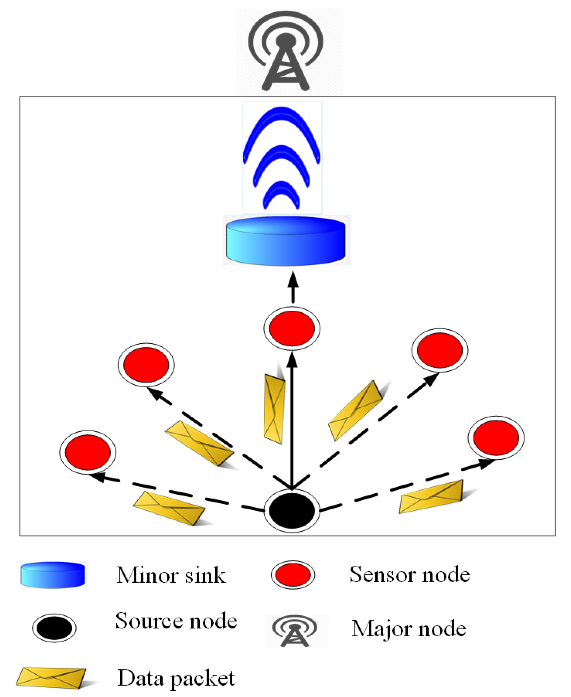
  • For delay minimization in dense underwater WSNs, the DMR scheme is designed in which the whole network is divided into four balanced zones. Four sink nodes are placed at the center of all zones, one node at the center of each zone. Placing sink nodes at the center of each zone reduces latency during information broadcasting, as packets do not have to follow the complete journey towards sea surface. Unlike the existing schemes, the DMR scheme reduces the path length for information transmission to the desired sink node. Information packets take minimum interval of time to reach the targeted major sink node as compared to other schemes. The DMR also copes with the problem of data traffic on the desired sink node, which is caused by the information flooding over the upper major sink node. This further causes packets congestion and drop. In each region, the sink node secures the information of the nodes, which are then transmitted to the major sink node. This balances transmission of information packets and reduces the packet traffic on the major sink node. It also avoids the problem of packet collision. The information flow from sink nodes towards the top sink node in different intervals of time ensures the steady traffic of information packets. DMR offers lower delay and energy consumption in packets advancement than some prevailing protocols as supported by simulation.
  • Packets are sent in DMR over a single link, which may not be reliable always as sea channel is very fluctuating. Therefore, to improving information bags reliability in DMR, cooperative routing is introduced making it CoDMR protocol. In CoDMR, all nodes that cannot directly forward information bags to minor sinks due to limited range, use the destination and relay nodes. A destination node is at lowest physical distance regarding the sink and a relay node is at the second lowest physical distance with respect to the sink. The destination requests the relay for information transmission when the BER of information is above a specific threshold. The destination uses fixed combining technique to decide about the quality of the data and further transmission of information bags. CoDMR is more reliable than some prevailing protocols in packets reliability as supported by simulation results.
  • The distance calculation is based on timer operation and does not use geographical coordinates as are usually required. In addition, unlike the conventional approach, placement of minor sink nodes is independent of the geographical position of the sink nodes, as obtaining this knowledge is really challenging in sea environment due to ocean currents and limited resources. These strategies make the DMR and CoDMR schemes easy to operate and time efficient with less complexity as compared to geographical coordinates based protocols.

2. Literature Review

This section contains the achievements and drawbacks of various routing algorithms and determines the main theme of all the schemes.
The scheme proposed in [14] is another cooperative fashion routing for underwater WSNs. Due to the division of the entire network into four equal regions, the scheme decreases the energy consumption and improves the network reliability. In an individual region, both the relay and destination nodes are preferred over the information of maximum residual energy and minimum depth value. A list having information of all neighbor nodes of source is set, in terms of depth information and residual energy value in descending fashion. The source broadcasts a hello bag to know about neighbors necessary information and later to share such information with them. The destination node receives two copies of information packets, from source and relay, which are further merged by using a combining technique. The scheme decreases the energy exhaustion and ensures the maximum information at the sink node, while it increases the latency the death rate of nodes.
The authors present a cooperative algorithm in [15] to minimize the network energy consumption and cope with unwanted channel conditions. It selects the destination and the relay nodes by considering the power level of a signal in response to noise level (SNR) and the physical distance among the neighbour nodes. A node forwards the information over the minimum path loss channel. For best forwarder node, the source node first collects the information of all neighbor nodes in terms of SNR and each node physical distance. The node having maximum SNR value and closed to the sink node is taken as destination. The relay node is also selected through the above criteria as a second node. The proposed scheme reduces the exhaust energy and maximizes the throughput. However, it has computational complexity due to calculation of SNR at every link.
A cooperative and reliable routing scheme for underwater WSNs is proposed in [16]. In the scheme, the selection of destination node is based on the minimum residual energy and least depth. The relay node is also chosen by using the depth information and remaining energy value. The source node broadcasts the packet and holds the information of neighbors in a list. The source node then forwards. The algorithm utilizes the flooding phenomena for the communication of information packets, while the network congestion is reduced by using depth threshold. It renders maximum packets to the sink node but exhausts excessive energy.
In the routing scheme proposed in [17], the authors utilize the distributed delay sensitivity routing algorithm. The approach has two objectives i.e., to improve the channel adaptability simply by forwarding the string of small packets during broadcasting and reduce the packet error rate by retaining the size of the broadcasted information packets. Channel transmission power, optimal node selection, and maximum information forwarding at the low cost of energy are the aims of the scheme. For delay reactivity, the scheme uses the random mobility of the nodes, which utilizes the node velocity and network density. It reduces the latency and improves the PDR while consumes high energy.
In [18], Chao et al. proposed an algorithm for underwater WSNs which reduces the latency of information during broadcasting. According to the scheme, when a node in the network forwards packets, then it waits for a certain time. The packets are transmitted frequently for a calculated interval of time with calculated transmission probability denoted. The best forwarder node receives the packet with a fixed calculated probability in the network. The transmission process is successful if the destination receives the packets. In this approach, due to the lack of channel reservation, the network throughput and delay are influenced by the transmission rate. Moreover, the attributes of the scheme are free from the distance between the nodes which overcomes the void space problem. The scheme outperforms the counterpart schemes in network throughput and latency and consumes high energy.
In [19], the authors propose a scheme to save the energy and enhance the network throughput. For this purpose, four movable sinks are considered which move according to the sender node position. The movement of the sink is considered only for the horizontal axis, which decreases the latency due to the sink movement. When the sink stays for a specific interval of time, nodes nearest to that sink, forward their information. The best forwarder nodes (destination and relay node) are selected by calculating the distance regarding the movable sink node. If any sink node is available in the sender broadcasting range, then nodes forward their information towards it. However, if the sink is not available in the sender field then cooperation performs. This approach outperforms in terms of network energy consumption. However, it blindly selects the channel link for transmission data which effects the PDR. The Table 1 shows the technique used, accomplishment and deficiency of the delay sensitivity schemes.
In [20], the source node chooses the best forwarder node using its depth and nodes present in its vicinity. Further more, a depth threshold is applied to select the relay node. Path set up is established through a calculated metric to reduce the latency, which considers the source node with a reference from the sink node. The proposed approach improves the scheme in [12] in which the source node forwards the information to the nodes which have best links for data advancement. The proposed algorithm renders good network throughput and engrosses small amount of energy at the cost of compromised reliability.
In [21], the authors present a new cooperative fashion routing algorithm to reduce the channel effects. The whole network is divided into three equal zones to balance the energy consumption. The source node broadcasts a hello bag, the information of node ID, residual energy and signal to noise ratio (SNR) of all neighbor nodes in the communication dimension are embedded into hello bag. For localization, the received signal strength indication (RSSI) is used instead of geographical information. The mote track technique is used for path identification. The sink nodes move horizontally and vertically and cover the whole network. The source node broadcasts information packet directly if the sink node is inside the transmission range. However, if sink node is away from the transmission range, the source node then chooses the best forwarder nodes as relay and destination nodes. Both the relay and destination nodes are chosen by considering the values of the highest remaining energy, and minimum SNR. The destination node secures the two copies of information packet due to cooperation. Which are merged using diversity technique. It increases the link quality but depletes energy of nodes quickly.
To maximize the network lifespan and upgrade the entire network throughput, the authors present a routing scheme in [22]. The network is divided into rectangular regions. The mobile sink nodes movements in clockwise directions cover all the regions. The source node transmits a hello packet which contains the information of each neighbor node ID and the information of sink node coordinates. Node broadcasts the information packets directly to the sink nodes due to the movability of the desired sink nodes. The network consumes low energy. However, this approach is deprived of checking the accuracy of the received information.
In [23], RAHMAN et al. present a scheme to save energy and enhance the network link quality. The proposed scheme improves the link quality due to the cooperation. The relay and destination nodes are selected by considering a criterion function using lowest depth information and maximum residual energy. The node having minimum depth and maximum remaining energy is considers as the destination node. A second such node is a relay node. The fuzzy logic technique is utilized to select the optimal forwarder node between the multiple relay nodes. The destination node checks the received packet. If BER exceeds the desired threshold value, then it sends a request to the relay node to send the received information. The desired relay node then forwards the information packet and sends an acknowledgement also towards the destination node. The two received packets are merged through a diversity scheme. The scheme improves the network reliability and saves the network energy. However, sending acknowledgement with multiple relays costs high delay. The below Table 2 shows the overview of all the reliable schemes.
In [24], Sahar et al. present non-cooperative and cooperative schemes. Where the non-cooperative algorithm decreases exhaust of energy, the cooperative scheme ensures maximum received information to the sink node. In non-cooperative scheme, the best forwarder nodes are selected by considering remaining energy, hop count and BER, which reduces both the network exhaust energy and the latency. While the cooperative scheme increases the reliability by using cooperation using a single relay. The node having maximum remaining energy, the limited number of hops and lowest BER is considered as a destination node while a second node with such attributes is a relay node. The algorithms reduces the exhaust energy, retains maximum nodes alive for a long period of time and improves information reliability. But it has high latency and complexity due to constant BER estimation.

3. Proposed Schemes

This section includes two proposed approaches, DMR and CoDMR, which are completely described.

3.1. Delay Minimization Routing (DMR) Scheme

3.1.1. Network Initialization:

The network consists of sensor nodes, four minor sink nodes, a major sink node and offshore data center as shown in Figure 1. The distribution of sensor nodes is random, which are capable of sensing data and responsible for forwarding the packets towards the minor sinks from where they are transferred to the major sink node. The entire network is split into four equal zones. To deploy minor sink nodes, the minor sink node S 1 is launched from the observation point a at sea surface and it travels downward with a speed of v m/s. It stops after a time interval t 1 calculated as below
t 1 = D 1 v
where D 1 is the depth from the surface observation points a to the point where S 1 stops. The interval t 1 is set in such a manner that the minor sink node S 1 stops at the top left subzone of the network. The minor sink node S 2 takes the same interval of time to reach to the top right subzone of the network from the reference point b. Likewise, the time interval t 2 is taken by the minor sinks S 3 and S 4 to reach to the lower left and right subzones of the network from the surface reference points a and b, respectively. The time interval t 2 is calculated as
t 2 = D 2 v
where D 2 is the depth of the minor sinks S 3 and S 4 from the sea surface. This depth is the same for both S 3 and S 4 . The minor sink node S 3 forwards the information towards the S 1 that sends it to the major sink node as shown in Figure 2. On the other hand, the minor sink node S 4 broadcasts the received packets to S 2 , which are further forwarded towards the major sink as indicated in Figure 3. The minor sink nodes S 1 and S 2 recognize the information coming from each other by their IDs. Therefore, S 1 and S 2 forward packets to major sink only when they receive them from S 3 and S 4 , respectively. Conversely, S 3 and S 4 do not accept packets from S 1 and S 2 .

3.1.2. Neighbour Identification and Path Setup

This phase includes the DMR algorithm neighbours recognition and path establishment. Initially, the nodes are unaware about the information of physical distance and node IDs among the neighbours. For this purpose, every minor sink node broadcasts a hello packet that contains its ID and the time at which the hello bag is broadcasted. The nodes in vicinity of the minor sink nodes receive the hello packet and compute their physical distance from the time difference when they receive the hello bag and when it was initially transmitted by the sink node, assuming a constant speed of acoustic wave. After reception, the neighbor nodes broadcast the hello bag and put their IDs, time at which they broadcast the hello bag and the time it was originally broadcasted by the minor sink node. When other nodes receive this hello bag, they compute their physical distance from the minor sink node and also know about the physical distance of every node from which they receive the hello bag. This process goes on until all nodes have the information of their physical distance from the minor sink node and of their neighbor as well. The hello packet is shown in Figure 4. Minor sink nodes and other sensor nodes regularly share this information to keep updated about information of each other [25]. All the four minor sink nodes are differentiated from the ordinary sensor nodes by their unique IDs. This differentiation of the minor sink nodes is helpful in recognizing them by the sensor nodes when the sensor nodes have to advance packets.

3.1.3. Best Forwarder Node Selection and Information Transition

When a source node broadcasts an information packet, it first checks whether the physical distance between itself and any of the minor sink node is less than than the defined communication range. If it is so, the source node hands over the information to the minor sink node directly. Otherwise, the source node selects a node that acts as a forwarder node and advances the information of the source node to the minor sink node. The forwarder node is the one that is nearest to the minor sink node and is recognized by the source node based on the information acquired during the exchange of hello bags among the nodes. The minor sink node further forwards the information to the major sink as shown in Figure 5.

3.2. Cooperative Delay Minimization Routing (CoDMR) Scheme

The CoDMR scheme introduces cooperative routing to the DMR scheme to make it CoDMR. Cooperative routing adds reliability to information transfer over the channel by involving a single relay node, in addition to the source and destination. This process is further explained as below.

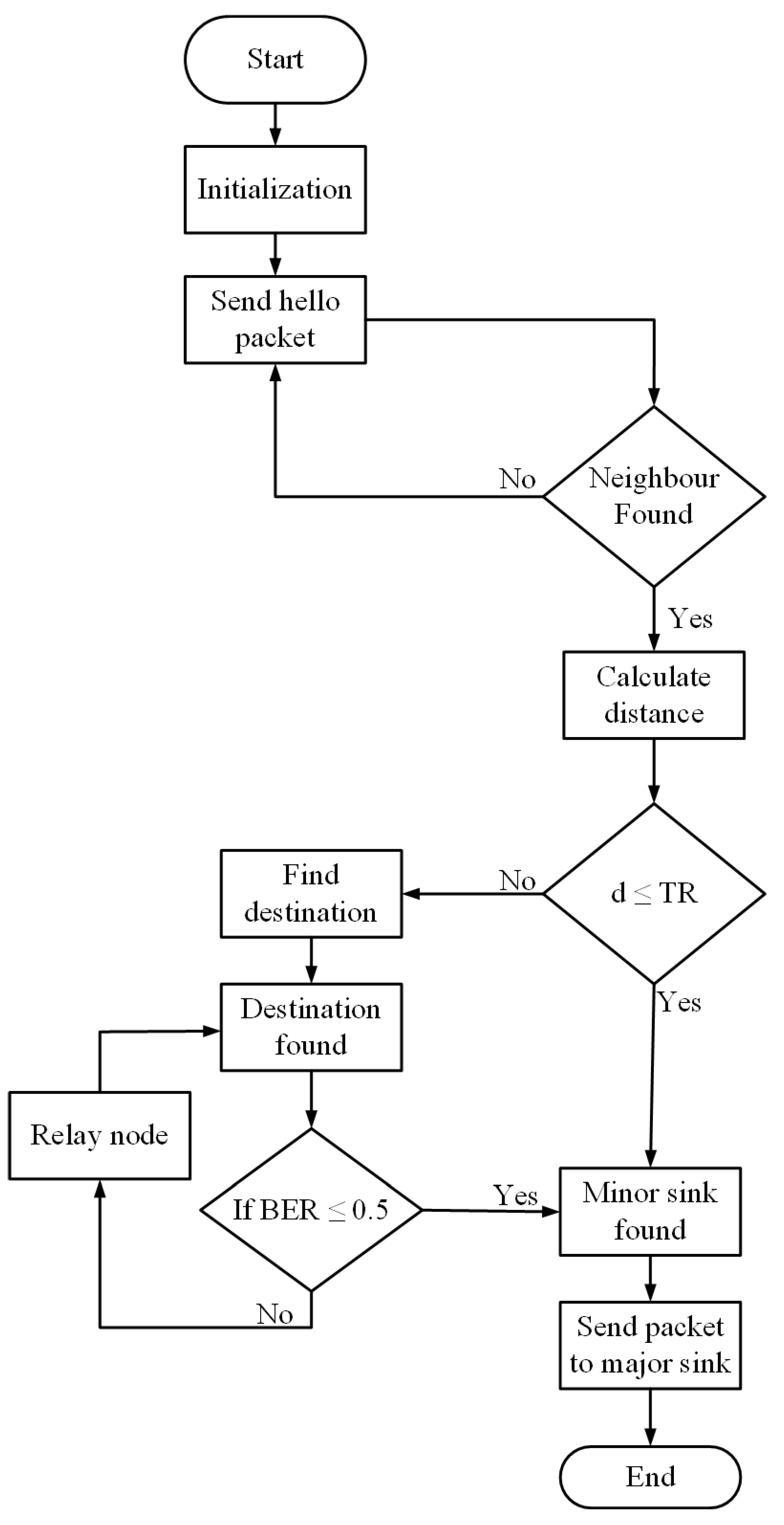
Data Forwarding and Cooperation:

In CoDMR protocol, the data packets are forwarded into two ways i.e., direct communication and relaying or cooperative communication as shown in Figure 6. In direct communication, when one or more source nodes have one or more minor sink nodes inside their communication range, the former advance the information to the latter.
However, if the minor sink nodes are beyond the communication range of the source nodes, then cooperative routing is applied, makes DMR as the CoDMR scheme. In the CoDMR algorithm, to ensure a reliable data delivery, the source node chooses the destination node, from the set of the neighbour nodes, which is closest to the minor sink. The node having lowest distance with respect to minor sink node is considered the destination node. A node that is second closest to the minor sink node is nominated as a relay node. The source node broadcasts the information packets towards the destination and the relay node. The destination checks the BER of the information packet, if BER is lower than the desired threshold value then it forwards the information directly to the minor sink node. However, if BER exceeds the threshold value, then it sends a request to the relay node to send the same information. The relay node then forwards the information along with the acknowledgement towards the destination node. Each destination node utilizes a diversity scheme to merge the two received packets (form source node and relaying). Fixed ratio combine (FRC) is used as a diversity technique instead of maximal ratio combine (MRC) because MRC requires the full channel state information (CSI), which is challenging in underwater environment as the channel fluctuates rapidly due to ocean currents and marine life. The received packets at the destination node, by using a single relay, can be designated as [26].
Y d = K 1 Y s d + K 2 Y r d
The Y d represents the merge of the two information packets reached at the destination node. The Y s d is the packet secured by the destination node directly from source node. Also, Y r d is the received packet from relay to destination. The variables K 1 and K 2 are the weighted constant ratios of the two links. These weights constant are the function of channel coefficients and can be express as [26].
K 1 K 2 = P 1 G s d P 2 G r d
where P 1 and P 2 are the two links power from the source towards the destination and from source in the direction of relay node, respectively. The symbol G s d indicates the channel gain from source towards the destination and G r d shows the channel gain in the direction of the destination node from the source node. In case of the special type of amplify and forward cooperation, the optimal value of the weight constant ratios is 2:1 and can be represent as [27].
K 1 = P 1 G s d σ 0
K 2 = P 2 G r d σ 0
Here σ 0 shows the signal variance, if the packet is transmitted with an average power of unity, the signal to noise ratio (SNR) can be computed through FRC as [27].
ρ = P 1 | G s d | 2 + P 2 | G r d | 2 σ 0
The information combined at destination is further evaluated for the extraction of the desired information packets. The destination then advances the information to an in-range minor sink node or this process is repeated unless the information is received by one of the minor sink nodes. Information from the lower two minor sink nodes is broadcasted towards the upper two minor sink nodes, from where the information is further broadcasted towards the top major sink. The below Figure 7 indicates the flow chart of both the protocols. While Algorithm 1 clearly describes the path setup, relay selection and data forwarding for both the schemes.
Algorithm 1: Information sharing, path set up and data forwarding
1 R L n :Relay node
2   B E R :Bit Error Rate
3   S R n :Source node 
4   T R :Transmission range
5   D T n :Destination node
6  N:Total number of rounds
7   S m a j o r :Major sink node
8   S m i n o r :Minor sink node
9   H p :Transmitted hello packet
10  d:distance from sensor node to minor sink nodes
11           Nodes transmits hello packet= then
12           Find neighbors
13           Neighbors found= true
14 if         d < T R = then
15           Find  S m i n o r
16            S m i n o r found
17           Send packet to S m i n o r = true
18           else if
19                   S m i n o r is not exist in the T R = then
20                  Find  D T n
21                  Calculate d for D T n selection
22                   D T n found= true
23                  if BER < 0.5= then
24                                  Find  R L n
25                                   R L n found= true
26                                  Packet send to  R L n
27                             while
28                                          Checks  S m i n o r
29                                          Packet reached to  S m i n o r
30                                          Packet forward to S m a j o r = true
31                          end if
32                  end if
33            end while
34 break

4. Simulation Results and Analysis

This section includes the simulation outcomes of both the DMR, CoDMR and some existing routing algorithms, all simulated in MATLAB. The DMR and CoDMR schemes are compared with the CoDBR [13] and DBR [28] protocols. The reason behind this comparison is that, that the CoDBR is a cooperation based-based routing scheme just like like CoDMR except that the former uses two relays while the latter uses one relay node. Moreover, the DBR is a non-cooperative single-path path -routing scheme, and the DMR is also non-cooperative single- path scheme and DBR uses low depth nodes to reduce delay while DMR uses minor sink nodes to avoid propagation delay due to multi-hopping. The network contains of 500 sensor nodes, which are distributed in arbitrarily in the ocean environment. The network is a 3D sphere having with each side 500 m. Initially, all the nodes in the underwater acoustic network possess with 10 J energy. The acoustic link quest UWM 1000 modem is used in the network. The total bandwidth is 30 kHz, while the transmission range is 100 m. The transmission power is 2 W and the receiving power is 0.1 W. The size of data packet is 1600 bits and transmitting rate is 10 kbps. The simulations results are averaged over 50 runs as the behavior of each scheme ceased to fluctuate after 50 runs. The below Table 3 shows the simulation parameters.

4.1. Nodes Depleted of Battery Power:

The Figure 8 shows the relative comparison of the proposed DMR and CoDMR protocols with the DBR and CoDBR. The number of nodes which depleted their battery power in DMR and CoDMR is minimum as compared to the counterpart schemes. The reason for this is due to the network division into four equal zones in DMR and CoDMR. Because of which nodes use less energy to forwards information towards the desired minor sink nodes. This helps to balance the energy cost amongst the nodes. In the DBR and CoDBR algorithms, nodes are died quickly as compared to the proposed schemes. The reason is that the DBR and CoDBR protocols transmit heavy information packets over the long transmission path to the upper sink node. Which exhausts high energy and drain their battery quickly. In the CoDBR protocol, two best relays are selected with the destination node for data forwarding, which also exhausts high energy. While the proposed CoDMR scheme uses a single relay with destination node, which also consumes lower energy than CoDBR and saves the battery power. While the DBR algorithm forwards the packets by considering the lowest depth, which makes a high load on the lowest depth nodes and die quickly. Therefore these nodes deplete battery power quickly than the proposed protocols. At round 600, the number of that have depleted battery power in DBR is 450 while CoDBR have more than 450 nodes. At the same instant, the CoDMR protocol has lower than 450 nodes and DMR scheme has the minimum number of nodes which depleted their battery power. After round 600, the depleted power nodes in the DBR and CoDBR algorithms are the same as these are the few nodes that participate in routing without availability of enough neighbor nodes.

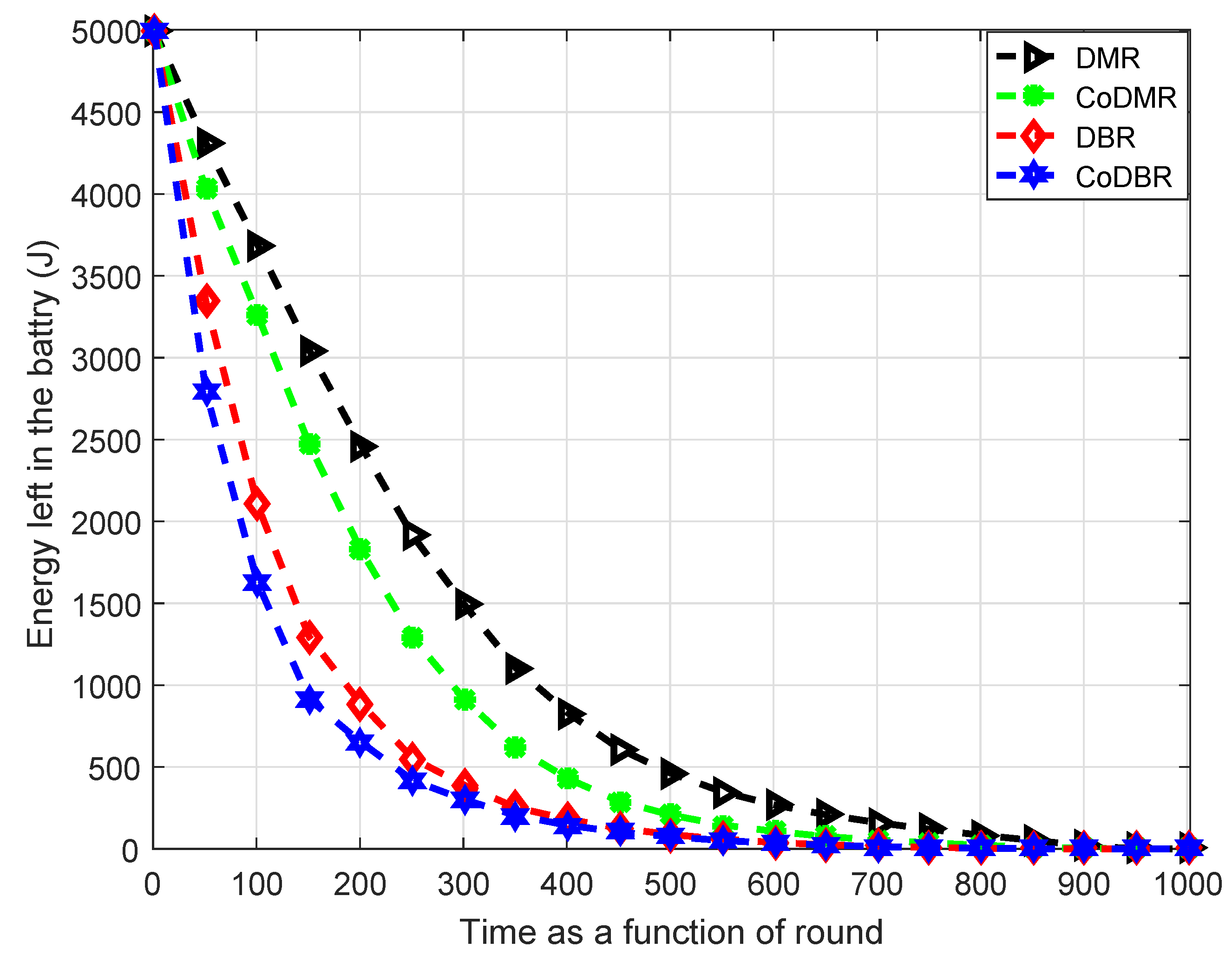
4.2. Energy Left in the Battery:

As shown in Figure 9, the energy left in the battery of the proposed algorithms is maximum than the CoDBR and DBR protocols. Because the CoDBR protocol forwards the data packets with the cooperation of two relay nodes, it consumes extra energy than the counterpart CoDMR scheme, which uses only a single relay. Combining it with the redundant information transmission in CoDBR, makes minimum energy left in batteries of the sensor nodes in CoDBR. While in DBR, the reason of the minimum energy left in the battery is due to the unbalance energy consumption as compared to DMR scheme. In DBR scheme, transmission of information over long paths is also reduced due to minor sink nodes availability within the network. As a result, the DMR scheme balances the energy cost, which saves the battery power. The DMR scheme also reduces the transmission path length and ensures maximum energy left in the battery of nodes. Likewise, the proposed DMR scheme has lower energy consumption than the CoDMR scheme. Because DMR is non cooperation scheme while the CoDMR scheme uses the cooperation. As a result minimum energy left in the battery of the CoDMR scheme nodes, as cooperation uses extra nodes as relays in addition to transmitter0receiver pair. Initially, all nodes in the network have maximum energy left in the battery. At round 200, the value of the energy left in the battery of nodes in the DBR is near to 1000 J and that of CoDBR is lower than 1000 J. At the same time, the energy left in the battery of nodes of the CoDMR is near to 1500 J and the DMR scheme maintains the highest energy of 2000 J. This indicates that the DMR and CoDMR schemes have more energy left in the batteries of nodes than DBR and CoDBR. After round 200 to round 800, the energy left in the battery of all schemes are different due to the reason explained above.

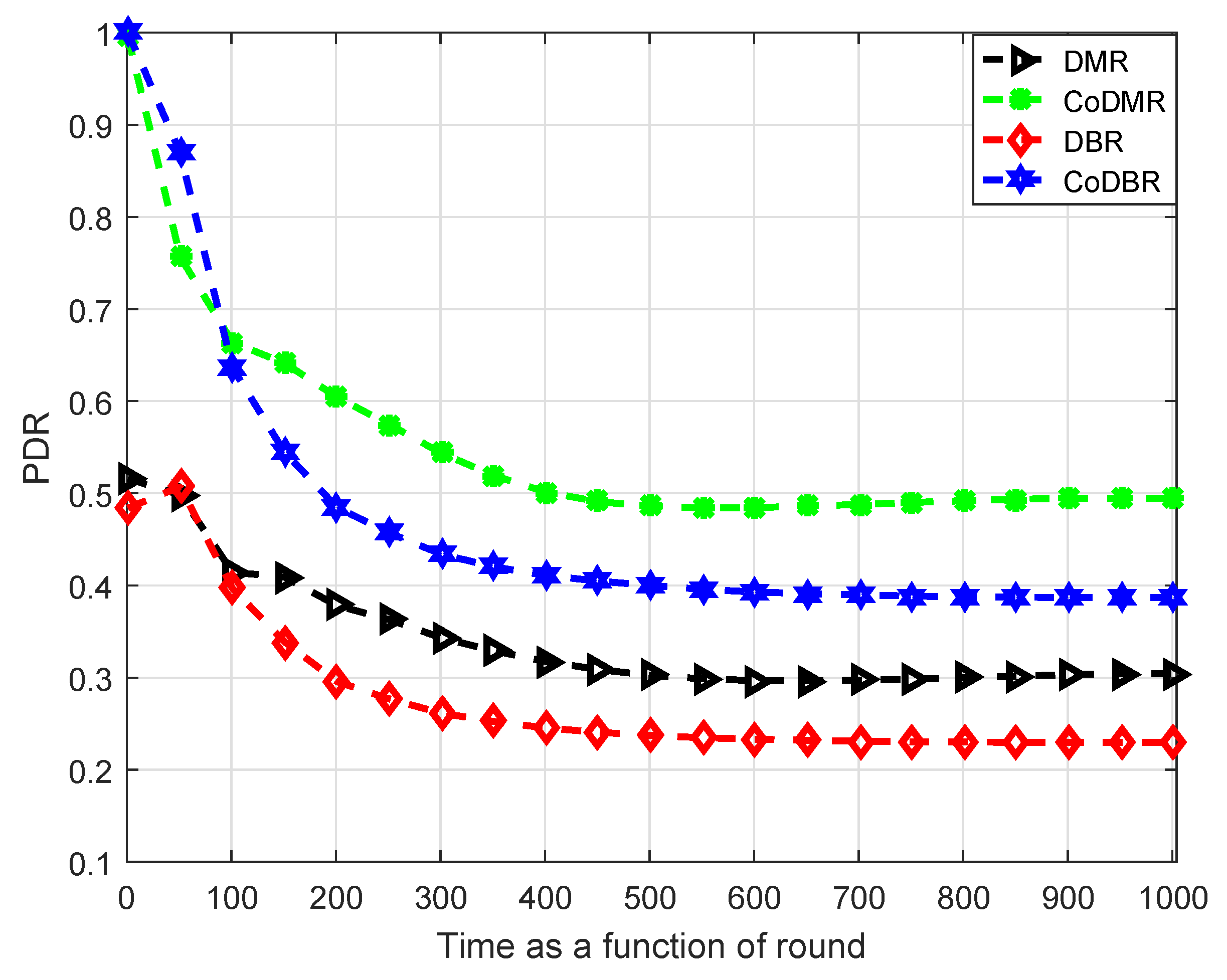
4.3. Packets Delivery Ratio

The Figure 10 indicates the analysis of PDR of the proposed algorithms with the CoDBR and DBR algorithms. The PDR of the CoDMR is highest for significant number of rounds. The reason of ensuring the maximum PDR of CoDMR protocol is tha the cooperation of a single relay node and placement of the minor sino nodes in the network. In the CoDMR scheme each node easily transmits the information to the desire minor sink node and maximum number of packets are reached successfully. Which ensures maximum information received by the major sink node and enhances the PDR. Nodes close to the minor sink node in each region send the information packets directly to it. While the farther nodes send the information via the cooperation of a single relay node. By using this mechanism, the ratio of packets dropped reduces as compared to the counterpart protocols and secures the highest PDR. The PDR of the DMR scheme is also better than the DBR because the DMR algorithm confronts the lowest depth node burden problem faced by the DBR scheme. Initially, the PDR value for CoDBR and CoDMR schemes starts from 1 due to cooperation, while DBR and DMR protocol starts from 0.5 due to non-cooperation, as cooperation brings reliability in information delivery. The CoDBR protocol has greatest PDR value than the other protocols till round 100. The reason behind this achievement is that the CoDBR protocol forwards data packet in cooperative manner and two relay nodes are contribute with the destination node. At the beginning, there is less chance of packet dropped. However, after round 100, the contribution of two relays consume maximum energy and nodes die swiftly as compared to CoDMR protocol. In CoDMR protocol, after round 100, the accomplishment of the reliable PDR is due to the fact of energy balancing technique. Which make nodes alive for long span of time and hold a reliable PDR till the last round. While the reason for enhanced PDR in the DMR scheme compared to DBR scheme is due to the avoidance of long transmission path.

4.4. Total End-to-End Delay

The total E-2-E latency of the four schemes is interpreted in Figure 11. The CoDBR and the DBR protocols have more delay than the DMR and the CoDMR protocols. This is due to the fact that the CoDBR scheme works in cooperative mode and in DBR the source node sends information packet from highest depth to the lowest depth destination node in the non-cooperative fashion. Both the existing schemes follow the long transmission path, which consumes a long amount of tim for information to reach the desired destination node. In the CoDBR scheme, a data packet passes to the two relays and to the destination node. The destination node checks all the packets channel condition and further forwards the optimal information to the sink node, which increases latency. While in proposed CoDMR algorithm; due to a single relay and the placement of minor sink nodes at the balance position, path length decreases, which reduces the delay during the packet transmission. The latency of the proposed DMR is minimum than the proposed CoDMR due to the single path routing. In each region, a node near to the minor sink nodes sends its information directly. While nodes away from the minor sink node, forward the data packets through cooperation with a single relay, by considering only the physical distance and time calculation. This technique reduces the transmission path and minimizes the delay. At round 600, the delay of the CoDBR protocol is much higher and is approximately 10 × 10 8 s, while the DBR scheme has the delay close to 6.5 × 10 8 s. At the same round, the CoDMR protocol has the delay lower than the DBR and CoDBR schemes and has 5 × 10 8 s. Moreover, the DMR scheme produces the lowest latency having the value of 3.5 × 10 8 s, which minimizes the delay in all rounds of the entire network and ensure fast packets transmission.

4.5. Total Energy Cost

Figure 12 describes the comparison of the four schemes in terms of total energy cost. Which shows that the energy cost of the DMR and CoDMR schemes is lower than the counterpart schemes. The reason of the lowest energy cost of the DMR algorithm is the balance energy utilization of the entire network, which enables the nodes to forward maximum information over the low cost of energy. While the reason of maximum energy cost in the DBR scheme, is the transmission of heavy packets from the highest depth source node to the lowest surface node, which increases the energy cost. Likewise, the CoDMR scheme also reduces the energy cost simply by enforcing a threshold that, a node close to the targeted minor sink node forwards the information in a non cooperative manner. While the nodes away from the minor sink nodes forward the information in cooperative fashion. These strategies reduce the overall network energy cost and forwards maximum information to the major sink node. Secondly, in CoDMR scheme, placing the minor sink nodes at balance position in the network decreases the information flooding due the to long multi-path routing. In CoDBR scheme, the contribution of two relay nodes and long propagation path increase the total energy cost. At round 200, the energy cost of the DBR and CoDBR protocols is maximum and has the values of approximately 4000 J and 4500 J, respectively. While at the same number of round, the energy cost of the DMR and CoDMR schemes is much lower than the counterpart schemes and has the values of 2000 J and 2500 J relatively. This shows that the proposed schemes are energy efficient than existing schemes.

5. Conclusions

In this paper, two routing schemes: DMR and CoDMR, are proposed for dense underwater WSNs. The DMR scheme minimizes the latency and reduces the energy cost. While the CoDMR scheme enhances the network reliability. For both the schemes, the entire network is divided into four equal regions, with a minor sink node at the center of each region. These minor sinks are further connected with the major sink node positioned at the middle of the water surface. In DMR algorithm, a node that has a minor sink node in its transmission range sends data directly to the sink. CoDMR works when a node has minor sink outside its transmission range. In this case, multi-hopping is used. However, during the multi-hopping, cooperative routing is used in which a data sender node advances data to a node of interest via a relay node. This enhances the probability of reliably advancing data in that if one path is more affected by sea channel, the other may not be. The proposed schemes are analyzed with the DBR and CoDBR schemes by using the MATLAB simulator. Performance improvements are made by the proposed schemes in terms of total energy cost, energy left in the battery, latency, nodes depleted energy and packet delivery ratio.

Author Contributions

U.U. proposed and implemented the main idea under the supervision of H.M. and co-supervision of A.K., respectively. S.M.A., A.U.R. and V.K. streamlined manuscripts’ flow. I.A. and M.A. responded to comments of the reviewers.

Funding

This research received no external funding.

Acknowledgments

This research work is supported in part by the University of Malaya under Postgraduate Research Grant (PG035-2016A).

Conflicts of Interest

The authors declare no conflict of interest.

Abbreviations

The following abbreviations are used in this manuscript:
ACKAcknowledgement
BERBit error rate
CoDBRCooperative depth base routing
CoDMRCooperative delay minimization routing
CSIChannel state information
DBRDepth base routing
DFDecode and forward
DMRDelay minimization routing
DthDepth threshold
E-2-EEnd- to- end
FRCFixed ratio combine
IDIdentification
MRCMaximal ratio combine
PARPacket acceptance ratio
PATPacket arrival time
PDRPacket delivery ratio
PSDPower spectral density
REQRequest send
RFRadio frequency
RSSIReceived signal strength indicator
SNRSignal- to- noise ratio
TRTransmission range
TWSNsTerrestrial wireless sensor networks
UWMUnderwater modem
UWSNUnderwater wireless sensor network
WSNsWireless sensor networks

References

  1. Kuo, L.C.; Melodia, T. Cross-Layer routing on MIMO-OFDM underwater acoustic links. In Proceedings of the 9th Annual IEEE Communications Society Conference on Sensor, Mesh and Ad Hoc Communications and Networks (SECON), Seoul, Korea, 18–21 June 2012; pp. 227–235. [Google Scholar]
  2. Qadar, J.; Khan, A.; Mahmood, H. DNAR: Depth and Noise Aware Routing for Underwater Wireless Sensor Networks. In Proceedings of the Conference on Complex, Intelligent, and Software Intensive Systems, Matsue, Japan, 4–6 July 2018; pp. 240–251. [Google Scholar]
  3. Akyildiz, I.F.; Pompili, D.; Melodia, T. Challenges for efficient communication in underwater acoustic sensor networks. SIGBED Rev. 2004, 1, 3–8. [Google Scholar] [CrossRef]
  4. Akyildiz, I.F.; Pompili, D.; Melodia, T. Underwater acoustic sensor networks: Research challenges. Ad Hoc Netw. 2005, 3, 257–279. [Google Scholar] [CrossRef]
  5. Noh, Y.; Wang, P.; Lee, U.; Torres, D.; Gerla, M. DOTS: A propagation delay-aware opportunistic MAC protocol for underwater sensor networks. In Proceedings of the 18th IEEE International Conference on Network Protocols, Kyoto, Japan, 5–8 October 2010; pp. 183–192. [Google Scholar]
  6. Pompili, D.; Melodia, T.; Akyildiz, I.F. Routing algorithms for delay-insensitive and delay-sensitive applications in underwater sensor networks. In Proceedings of the 12th Annual International Conference on Mobile Computing and Networking, Los Angeles, CA, USA, 23–29 September 2006; pp. 298–309. [Google Scholar]
  7. Hsu, C.-C.; Liu, H.-H.; Gomez, J.L.G.; Chou, C.-F. Delay-Sensitive Opportunistic Routing for Underwater Sensor Networks. IEEE Sens. J. 2015, 15, 6584–6591. [Google Scholar] [CrossRef]
  8. Javaid, N.; Jafri, M.; Ahmed, S.; Jamil, M.; Khan, Z.A.; Qasim, U.; Al-Saleh, S.S. Delay-Sensitive Routing Schemes for Underwater Acoustic Sensor Networks. Int. J. Distrib. Sens. Netw. 2015, 11, 532676. [Google Scholar] [CrossRef]
  9. Partan, J.; Kurose, J.; Levine, B.N. A survey of practical issues in underwater networks. SIGMOBILE Mob. Comput. Commun. Rev. 2007, 11, 23–33. [Google Scholar] [CrossRef]
  10. Basagni, S.; Petrioli, C.; Petroccia, R.; Spaccini, D. CARP: A Channel-aware routing protocol for underwater acoustic wireless networks. Ad Hoc Netw. 2015, 34, 92–104. [Google Scholar]
  11. Fadoul, M.; Morsin, M.B.; Leow, C.Y.; Eteng, A.A. Using amplify-and-forward relay for coverage extension in indoor environments. J. Theor. Appl. Inf. Technol. 2016, 91, 304–312. [Google Scholar]
  12. Khan, A.; Ali, I.; Rahman, A.U.; Imran, M.; Mahmood, H.; E-Amin, F. Co-EEORS: Cooperative Energy Efficient Optimal Relay Selection Protocol for Underwater Wireless Sensor Networks. IEEE Access 2018, 6, 28777–28789. [Google Scholar] [CrossRef]
  13. Nasir, H.; Javaid, N.; Ashraf, H.; Manzoor, S.; Khan, Z.A.; Qasim, U.; Sher, M. CoDBR: cooperative depth based routing for underwater wireless sensor networks. In Proceedings of the 2014 Ninth International Conference on Broadband and Wireless Computing, Communication and Applications, Guangdong, China, 8–10 November 2014; pp. 52–57. [Google Scholar]
  14. Hafeez, T.; Javaid, N.; Shakeel, U.; Hussain, S.; Maqsood, H. An Energy Efficient Adaptive Cooperative Routing Protocol for Underwater WSNs. In Proceedings of the 2015 10th International Conference on Broadband and Wireless Computing, Communication and Applications (BWCCA), Krakow, Poland, 4–6 November 2015; pp. 304–310. [Google Scholar]
  15. Ahmed, S.; Javaid, N.; Khan, F.A.; Durrani, M.Y.; Ali, A.; Shaukat, A.; Sandhu, M.M.; Khan, Z.A.; Qasim, U. Co-UWSN: Cooperative Energy-Efficient Protocol for Underwater WSNs. Int. J. Distrib. Sens. Netw. 2015, 11, 891410. [Google Scholar] [CrossRef] [PubMed]
  16. Pervaiz, K.; Wahid, A.; Sajid, M.; Khizar, M.; Khan, Z.A.; Qasim, U.; Javaid, N. DEAC: Depth and energy aware cooperative routing protocol for underwater wireless sensor networks. In Proceedings of the 2016 10th International Conference on Complex, Intelligent, and Software Intensive Systems (CISIS), Fukuoka, Japan, 6–8 July 2016; pp. 150–158. [Google Scholar]
  17. Dubey, A.; Rajawat, A. Impulse effect of node mobility on delay sensitive routing algorithm in underwater sensor network. In Proceedings of the 2016 International Conference on Internet of Things and Applications (IOTA), Pune, India, 22–24 January 2016; pp. 437–442. [Google Scholar]
  18. Li, C.; Xu, Y.; Xu, C.; An, Z.; Diao, B.; Li, X. DTMAC: A Delay Tolerant MAC Protocol for Underwater Wireless Sensor Networks. IEEE Sensors J. 2016, 16, 4137–4146. [Google Scholar] [CrossRef]
  19. Shakeel, U.; Jan, N.; Qasim, U.; Khan, Z.A.; Javaid, N. DRADS: Depth and reliability aware delay sensitive routing protocol for underwater WSNs. In Proceedings of the 2016 10th International Conference on Innovative Mobile and Internet Services in Ubiquitous Computing (IMIS), Fukuoka, Japan, 6–8 July 2016; pp. 78–83. [Google Scholar]
  20. Shah, P.M.; Ullah, I.; Khan, T.; Hussain, M.S.; Khan, Z.A.; Qasim, U.; Javaid, N. MobiSink: Cooperative routing protocol for underwater sensor networks with sink mobility. In Proceedings of the 2016 IEEE 30th International Conference on Advanced Information Networking and Applications (AINA), Crans-Montana, Switzerland, 23–25 March 2016; pp. 189–197. [Google Scholar]
  21. Javaid, N.; Hussain, S.; Ahmad, A.; Imran, M.; Khan, A.; Guizani, M. Region based cooperative routing in underwater wireless sensor networks. J. Netw. Comput. Appl. 2017, 92, 31–41. [Google Scholar] [CrossRef]
  22. Abbasi, J.S.; Javaid, N.; Gull, S.; Islam, S.; Imran, M.; Hassan, N.; Nasr, K. Balanced Energy Efficient Rectangular routing protocol for Underwater Wireless Sensor Networks. In Proceedings of the 2017 13th International Wireless Communications and Mobile Computing Conference (IWCMC), Valencia, Spain, 26–30 June 2017; pp. 1634–1640. [Google Scholar]
  23. Rahman, M.A.; Lee, Y.; Koo, I. EECOR: An Energy-Efficient Cooperative Opportunistic Routing Protocol for Underwater Acoustic Sensor Networks. IEEE Access 2017, 5, 14119–14132. [Google Scholar] [CrossRef]
  24. Shah, S.; Khan, A.; Ali, I.; Ko, K.-M.; Mahmood, H. Localization Free Energy Efficient and Cooperative Routing Protocols for Underwater Wireless Sensor Networks. Symmetry 2018, 10, 498. [Google Scholar] [CrossRef]
  25. Majid, A.; Azam, I.; Waheed, A.; Zain-ul-Abidin, M.; Hafeez, T.; Khan, Z.A.; Qasim, U.; Javaid, N. An energy efficient and balanced energy consumption cluster based routing protocol for underwater wireless sensor networks. In Proceedings of the 2016 IEEE 30th International Conference on Advanced Information Networking and Applications (AINA), Crans-Montana, Switzerland, 23–25 March 2016; pp. 324–333. [Google Scholar]
  26. Chong, P.K.; Kim, D. Surface-level path loss modeling for sensor networks in flat and irregular terrain. ACM Trans. Sen. Netw. 2013, 9, 15. [Google Scholar] [CrossRef]
  27. Vakily, V.T.; Jannati, M. A new method to improve performance of cooperative underwater acoustic wireless sensor networks via frequency controlled transmission based on length of data links. Wirel. Sens. Netw. 2010, 2, 381. [Google Scholar] [CrossRef]
  28. Yan, H.; Shi, Z.J.; Cui, J.H. DBR: Depth-based routing for underwater sensor networks. In Proceedings of the International conference on research in networking, New Delhi, India, 2–14 December 2008; pp. 72–86. [Google Scholar]
Figure 1. Network model.
Symmetry 11 00195 g001
Figure 2. Minor sink S 1 and S 3 packet forwarding.
Symmetry 11 00195 g002
Figure 3. Minor sink S 2 and S 4 packet forwarding.
Symmetry 11 00195 g003
Figure 4. Hello packet format.
Symmetry 11 00195 g004
Figure 5. DMR packet forwarding operation.
Symmetry 11 00195 g005
Figure 6. Cooperation model.
Symmetry 11 00195 g006
Figure 7. Flow chart of DMR and CoDMR.
Symmetry 11 00195 g007
Figure 8. Nodes depleted of battery power.
Symmetry 11 00195 g008
Figure 9. Energy left in the battery.
Symmetry 11 00195 g009
Figure 10. Packet delivery ratio (PDR).
Symmetry 11 00195 g010
Figure 11. End-to-end delay in second.
Symmetry 11 00195 g011
Figure 12. Total energy cost.
Symmetry 11 00195 g012
Table 1. Analysis of the existing delay sensitive protocols.
ReferenceTechnique UsedAccomplishmentDeficiencyYear
[14]Cooperative region region-based routing algorithm, destination, and and relay node are selected by taking the lowest depth and maximum residual energy information, use maximal ratio combination (MRC) technique for diversity.Balance energy consumption, consume minimum energy, ensure maximum information at the sink node.Provide high latency during packet forwarding, nodes died quickly.2015
[15]Cooperative Cooperative-based routing protocol, destination, and relay node are chosen by considering the value of SNR and physical distance from the sink node.Cope the contrary channel effects, reduce energy consumption, increase the throughput.Reduce the network reliability, and dropped maximum information packets.2015
[16]Cooperative Cooperative-based protocol used Dth for reliability, the selection of best forwarder nodes is base over the lowest depth and highest remaining energy information, a diversity technique is used for packet combining.Improve the network reliability by providing good PDR, ensure maximum information at the sink node.Unbalance energy consumption, nodes died quickly, render high latency.2016
[17]Non-cooperative distributed delay sensitivity routing algorithm, best forwarder node is selected in the distributed manner, used train transmitted method to enhance channel efficiency.Reduce the latency during packet transmitting, improve the PDR.Unbalanced energy consumption, exhaust maximum energy.2016
[18]Non-cooperative protocol scheme used two different states the network is divided into m slots, propagation delay is influenced by the transmission rate, used different probability for transmission and receiving.Overcome the void space problem in the network, decrease latency, and and increase the throughput.Consume maximum energy due to the deficiency of the balance energy technique.2016
Table 2. Overview of the existing reliable protocols.
ReferenceTechnique UsedAccomplishmentDeficiencyYear
[19]Cooperative Cooperative-fashion algorithm, the best forwarder node is select by considering the lowest distance form the desired movable sink node, used sink mobility to reduce the latency and maintain a balance network.Balance energy consumption, enhance the network throughput, decrease latency.Select the channel link blindly which reduce the PDR.2016
[20]Non-cooperative algorithm, the best forwarder node selects by considering the node ID, depth information, and and the number of neighbors, used metric function for delay minimization.Balance energy consumption engross minimum energy, decrease latency.Decrease the network reliability and maximum information lost due to packet loss.2016
[21] Non-cooperative region region-based protocol, best forwarder node is selected through nodes ID, residual energy and SNR value, used RSSI for localization mote track technique is utilized for path establishment. Ensure maximum packet reached to the sink node, improve the PDR, and and hold a reliable network.Exhaust maximum energy in the network, nodes died quickly.     2017
[22]Non-cooperative rectangular region region-based scheme, used two mobile sinks, best forwarder node is chosen by considering the nodes ID and nodes coordinates.Ensure maximum packet received at the sink node, improve the network PDR, and and balance energy consumption.The scheme has no mechanism to check the accuracy of the received information.2017
[23]Cooperative Cooperative-based routing algorithm, relay and destination nodes are chosen by considers the values minimum depth information and residual energy, the fuzzy logic technique is applied to balance energy.The energy cost is minimum, increase the network lifespan, improve the link quality.Absence of packet analyzing appliance, decrease network accuracy.2017
[24]Present two schemes non-cooperative and non-cooperative protocols, the best forwarder nodes are selected through a function of maximum remaining energy, less number of fewer hops, and and lowest BER.Reduce the exhaust energy, balance energy consumption, improve the reliability.Provide high latency during packets transmission.2018
Table 3. Simulation parameters.
ParametersCalculated Values
Bandwidth30,000 Hz
Data packet size1600 bits
Depth500 m
Hello packet size48 bits
Idle mode exhaust power10 mW
Receiving power0.1 W
Total initial energy10 Joules
Total sensors nodes500
Transmission power2 W
Transmission range100 m
Major sink nodes1
Minor sink nodes4
Width500 m
Wind speed10 m/s

