Axisymmetric Arc Sliding Method of Basal Heave Stability Analysis for Braced Circular Excavations


Abstract
:1. Introduction
2. Proposed Axisymmetric Arc Sliding Method—AASM
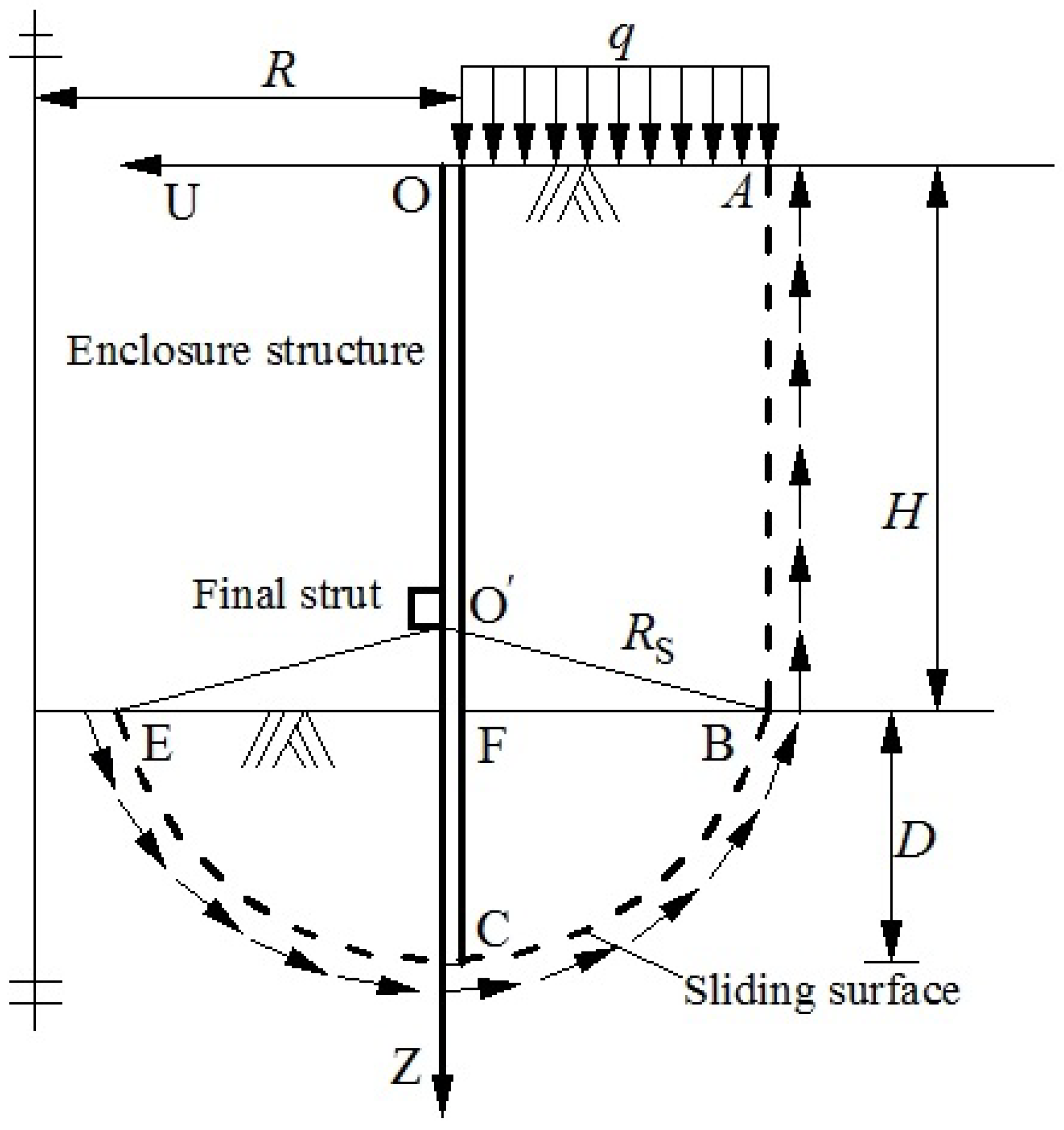
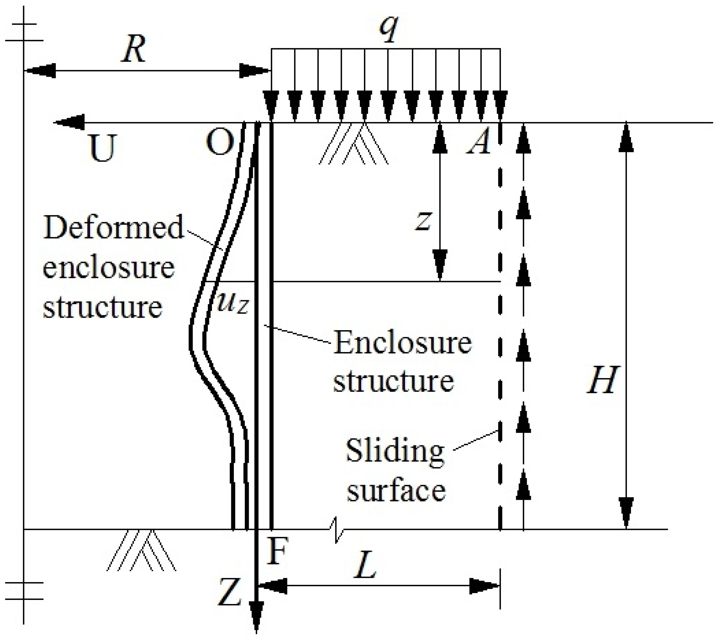
2.1. Problem Description
- (a)
- Soil slides alone the sliding surface ABCE, on which the shear stress provides the resistance moment
- (b)
- The constitutive relationship of soil can be modeled using Mohr-Coulomb model;
- (c)
- The term can be ignored in the active earth pressure formula and the term can be ignored in the passive earth pressure formula;
- (d)
- The spatial effects on the soil below the bottom can be ignored.
2.2. Formula of Axisymmetric Arc Sliding Method—AASM
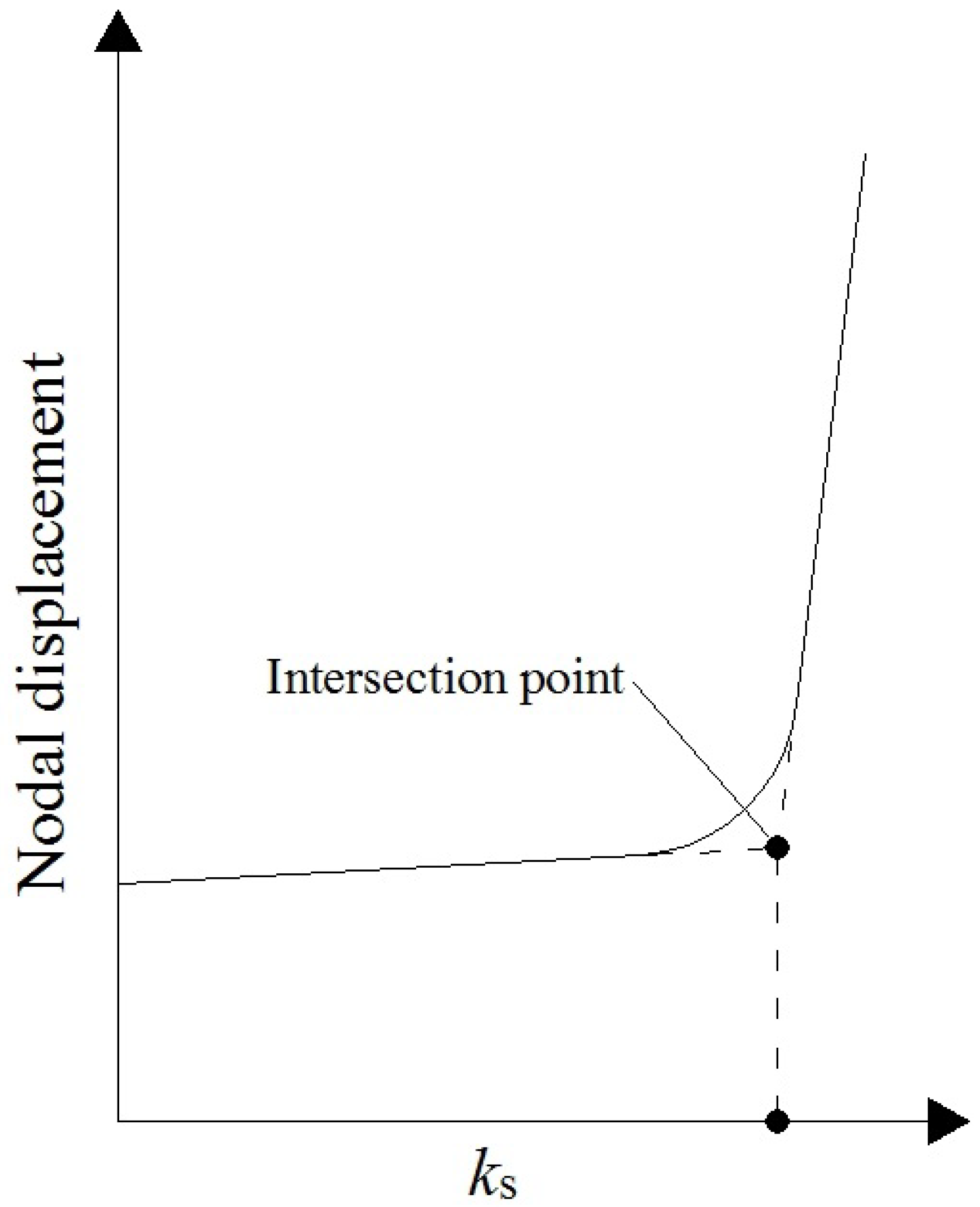
2.3. Flowchart and Parameters
3. Case Example
3.1. Example Parameters
3.2. Result of
4. Parametric Analysis
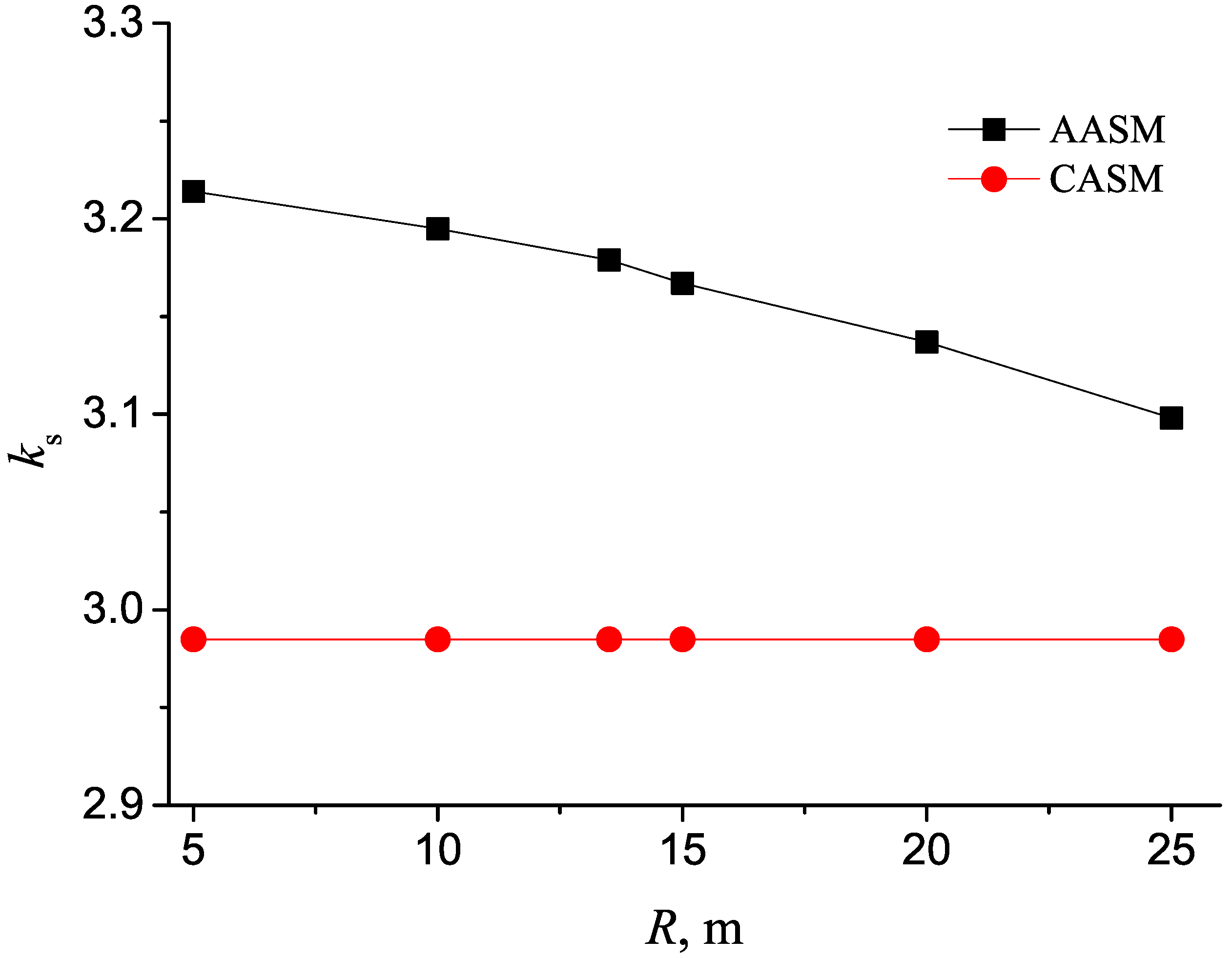
4.1. Radius Effect on in the Theoretical Solution
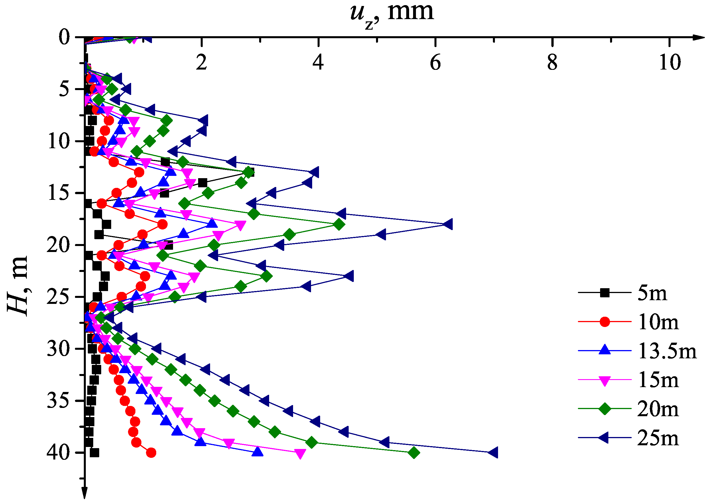
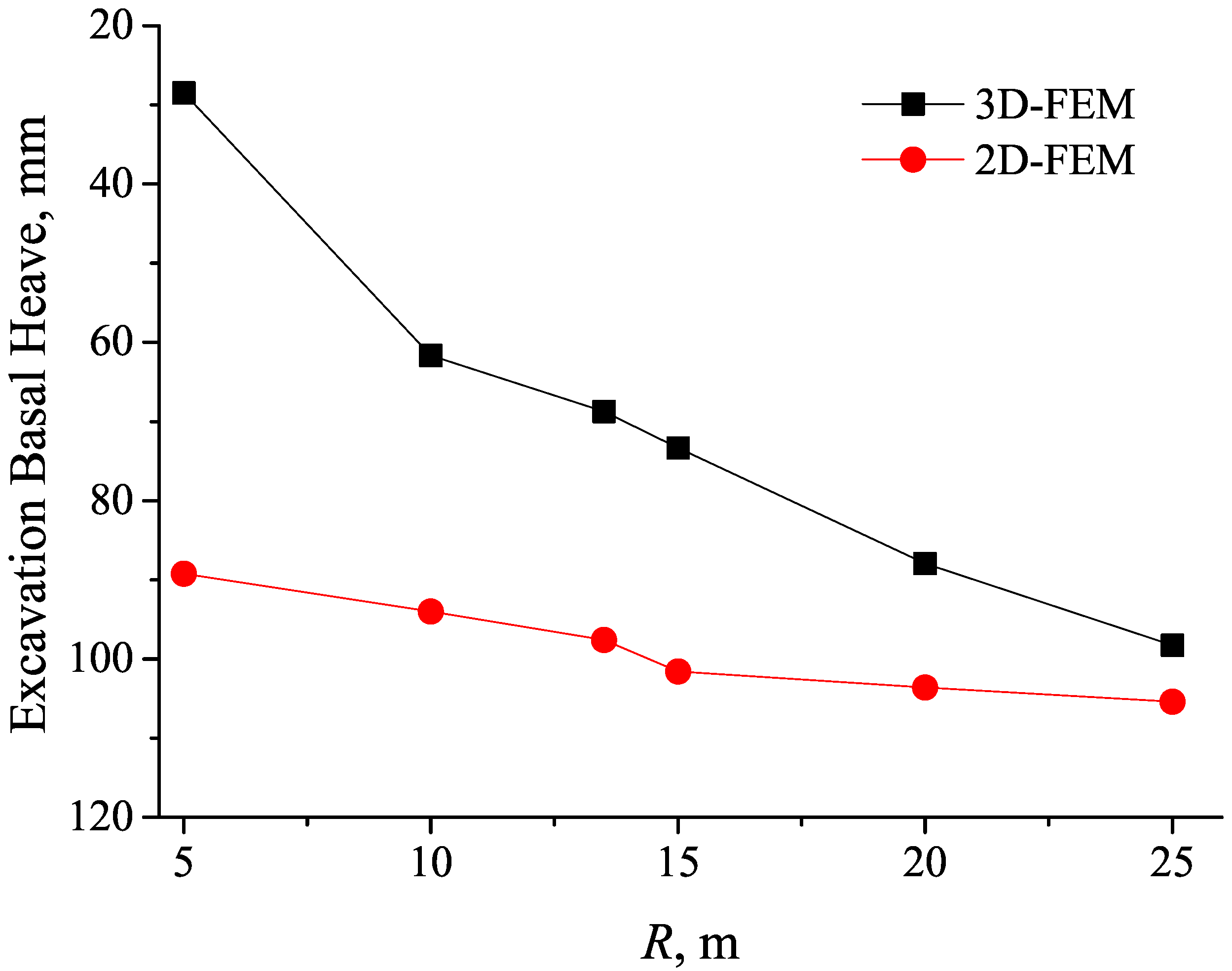
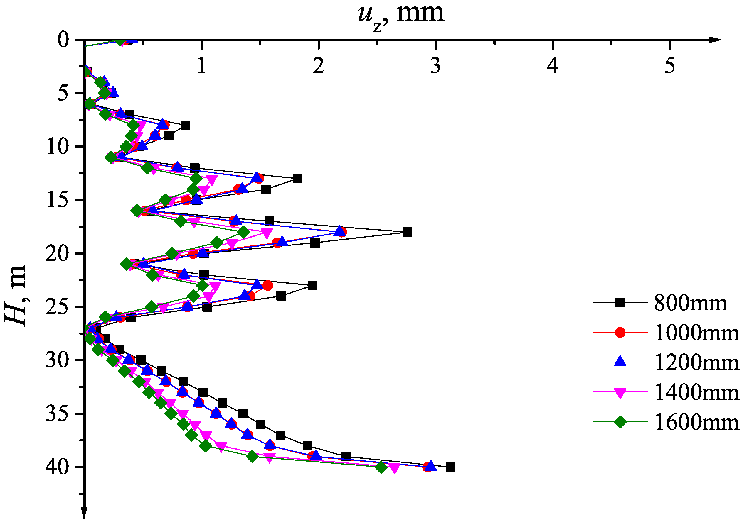
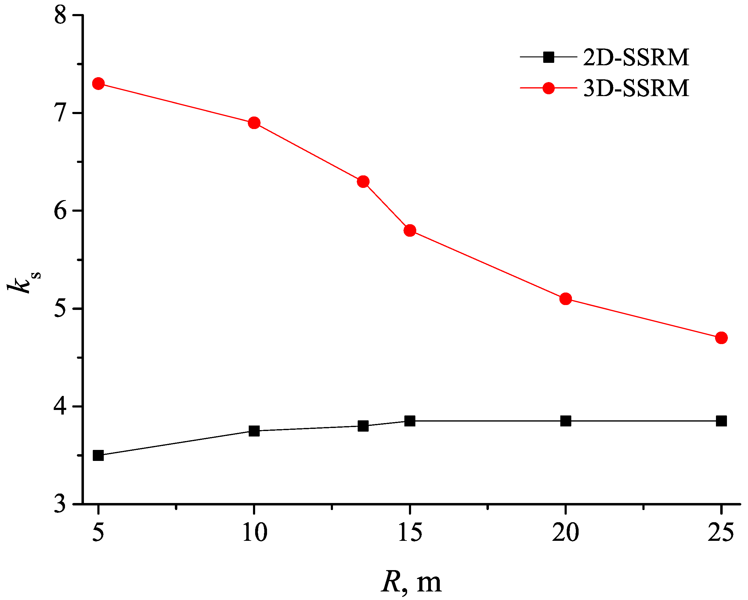
4.2. Radius Effect on in the Numerical Simulation
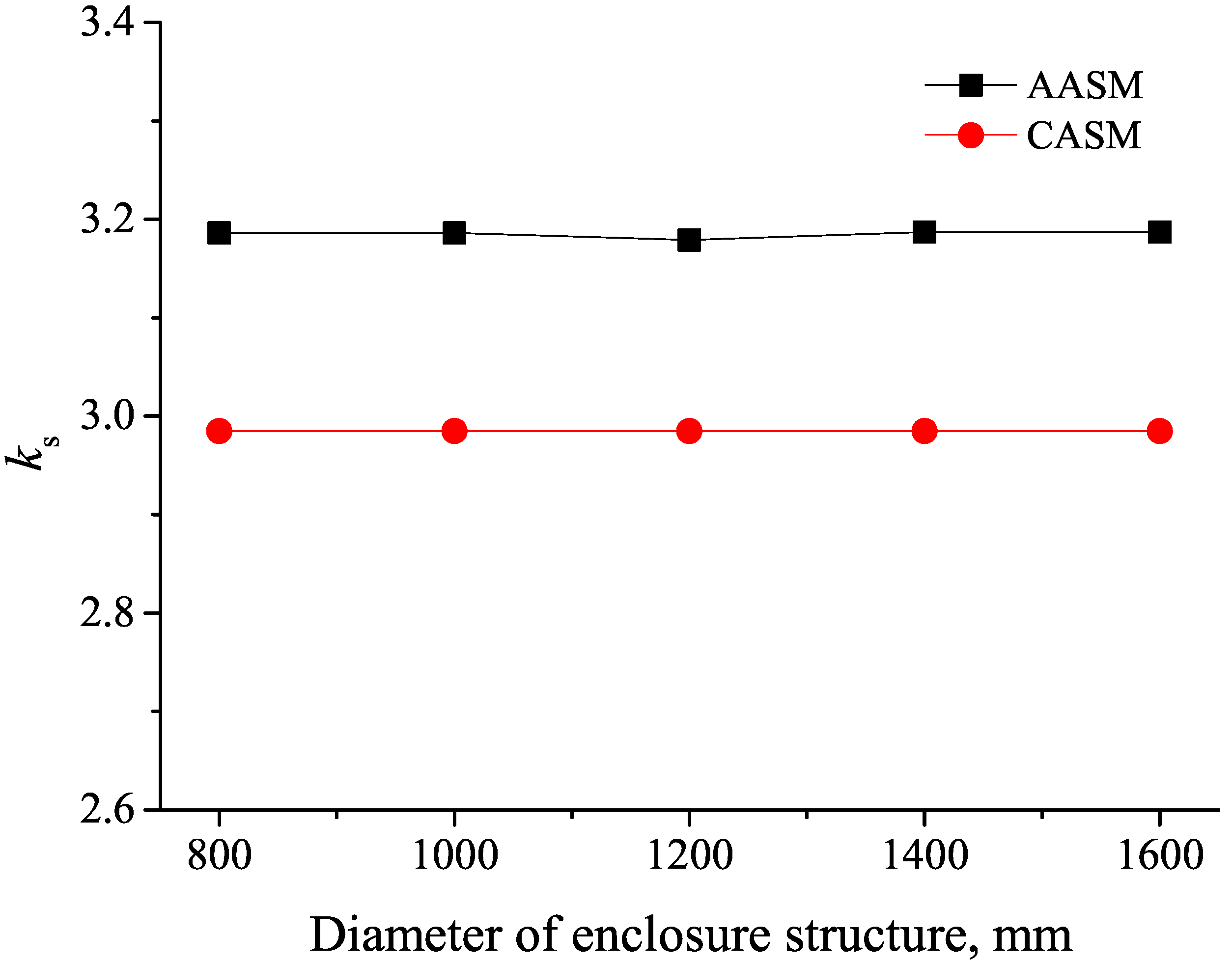
4.3. Enclosure Structure Stiffness Effect on
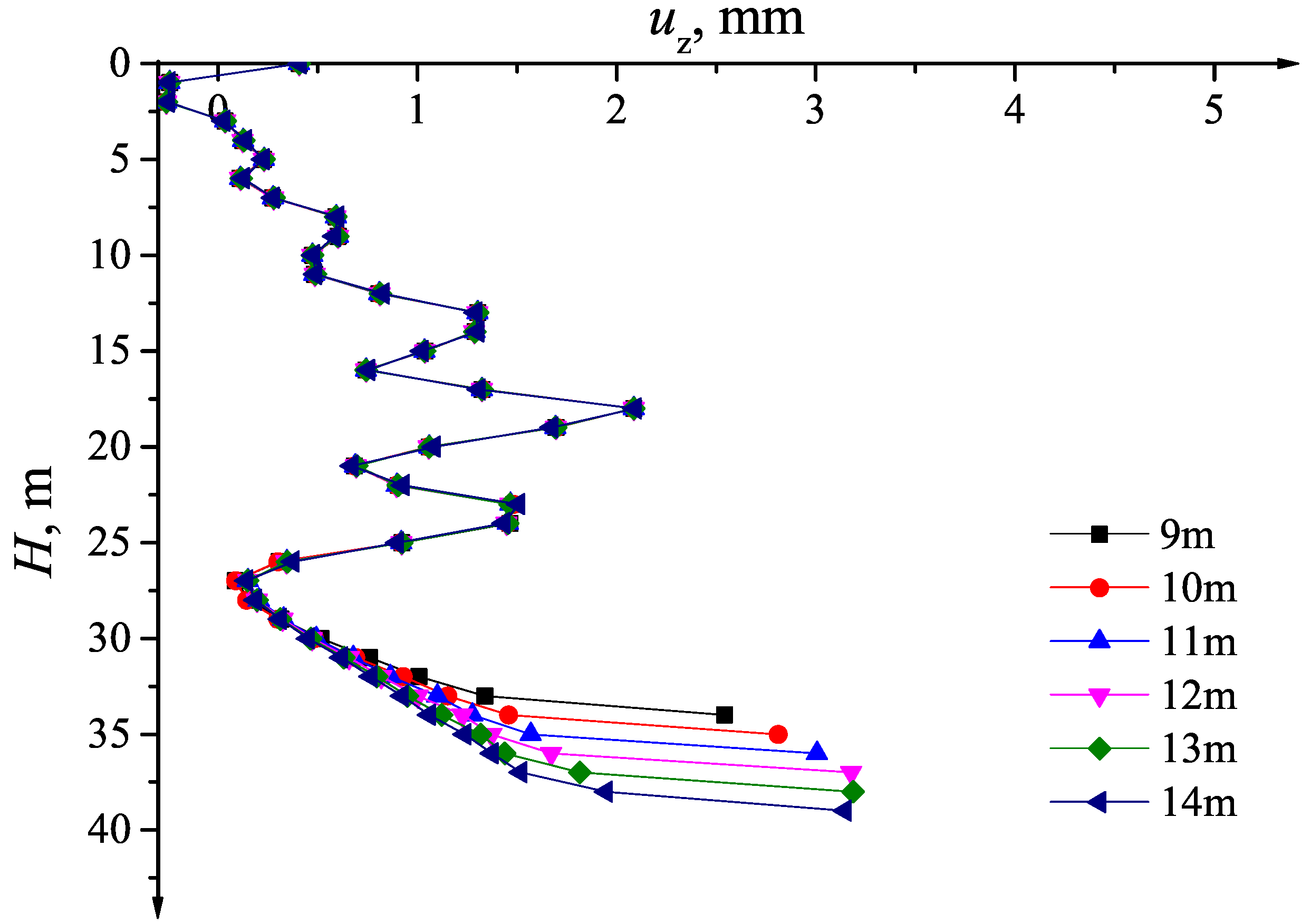
4.4. Embedded Depth Effect on
5. Conclusions
- (1)
- The AASM combines stiffness with deformation of the enclosure structure to check the basal heave stability of circular excavations and considers spatial effects.
- (2)
- The basal heave stability safety factor calculated with the AASM is higher than that calculated with the CASM. A design example demonstrates that the AASM results are reasonable.
- (3)
- A computation example revealed that, in the case of circular excavation, if basal heave stability safety factors are the same, the embedded depth of the enclosure structure may be reduced by 4∼5 m to lower the cost of the enclosure structure.
Author Contributions
Acknowledgments
Conflicts of Interest
References
- Tan, Y.; Wang, D.L. Structural Behaviors of Large Underground Earth-Retaining Systems in Shanghai. II: Multipropped Rectangular Diaphragm Wall. J. Perform. Constr. Facil. 2015, 29, 4014059. [Google Scholar] [CrossRef]
- Schwamb, T.; Soga, K.; Mair, R.J.; Elshafie, M.Z.E.B.; Sutherden, R.; Boquet, C.; Greenwood, J. Fibre optic monitoring of a deep circular excavation. Proc. Inst. Civ. Eng. Geotech. Eng. 2014, 167, 144–154. [Google Scholar] [CrossRef]
- Zhang, M.J.; Zhang, Z.B.; Du, X.L. Research on Number of Car Elevators for Cylindrical Underground Garage Based on Queuing Theory. China J. Highw. Transp. 2017, 30, 133–139. [Google Scholar]
- Terzaghi, K. Theoretical Soil Mechanics; John Willey and Sons: New York, NY, USA, 1943; pp. 118–143. [Google Scholar]
- Bjerrum, L.; Eide, O. Stability of strutted excavations in clay. Géotechnique 1956, 6, 32–47. [Google Scholar] [CrossRef]
- Zheng, G.; Cheng, X.S. Basal stability analysis method considering arc length and normal stress correction. Chin. J. Geotech. Eng. 2012, 34, 781–789. [Google Scholar]
- Chang, M.F. Basal stability analysis of braced cuts in clay. J. Geotech. Geoenviron. Eng. 2000, 126, 276–279. [Google Scholar] [CrossRef]
- Ukritchon, B.; Whittle, A.J.; Sloan, S.W. Undrained Stability of Braced Excavations in Clay. J. Geotech. Geoenviron. Eng. 2003, 129, 738–755. [Google Scholar] [CrossRef]
- Goh, A.T.C.; Kulhawy, F.H.; Wong, K.S. Reliability assessment of Basal-Heave stability for braced excavations in clay. J. Geotech. Geoenviron. Eng. 2008, 134, 145–153. [Google Scholar] [CrossRef]
- Wu, S.H.; Ou, C.Y.; Ching, J.; Hsein Juang, C. Reliability-Based Design for Basal Heave Stability of Deep Excavations in Spatially Varying Soils. J. Geotech. Geoenviron. Eng. 2012, 138, 594–603. [Google Scholar] [CrossRef]
- Luo, Z.; Atamturktur, S.; Cai, Y.; Juang, C.H. Reliability analysis of basal-heave in a braced excavation in a 2-D random field. Comput. Geotech. 2012, 39, 27–37. [Google Scholar] [CrossRef]
- Luo, Z.; Atamturktur, S.; Cai, Y.; Juang, C.H. Simplified Approach for Reliability-Based Design against Basal-Heave Failure in Braced Excavations Considering Spatial Effect. J. Geotech. Geoenviron. Eng. 2012, 138, 441–450. [Google Scholar] [CrossRef]
- Fan, L.; Wu, Z.; Wan, Z.; Gao, J.W. Experimental investigation of thermal effects on dynamic behavior of granite. Appl. Therm. Eng. 2017, 125, 94–103. [Google Scholar] [CrossRef]
- Wu, Z.; Fan, L.F.; Liu, Q.; Ma, G.W. Micro-mechanical modeling of the macro-mechanical response and fracture behavior of rock using the numerical manifold method. Eng. Geol. 2017, 225, 49–60. [Google Scholar] [CrossRef]
- Wu, S.H.; Ou, C.Y.; Ching, J. Reliability based design of base heave dtability in wide excavations. In Geo-Risk 2011: Risk Assessment and Management; American Society of Civil Engineers: Reston, VA, USA, 2011; pp. 680–687. [Google Scholar]
- Goh, A.T.C. Estimating basal-heave stability for braced excavations in soft clay. J. Geotech. Eng. 1994, 120, 1430–1436. [Google Scholar] [CrossRef]
- Hashash, Y.M.A.; Whittle, A.J. Ground Movement Prediction for Deep Excavations in Soft Clay. J. Geotech. Eng. 1996, 122, 474–486. [Google Scholar] [CrossRef]
- Do, T.N.; Ou, C.Y.; Asce, M.; Lim, A. Evaluation of Factors of Safety against Basal Heave for Deep Excavations in Soft Clay Using the Finite-Element Method. J. Geotech. Geoenviron. Eng. 2013, 139, 2125–2135. [Google Scholar] [CrossRef]
- Wang, H. Stability Analysis of Retaining Structure for Circular Foundation Pit. Chin. J. Undergr. Space Eng. 2011, 7, 1653–1659. [Google Scholar]
- Khatri, V.N.; Kumar, J. Stability of an unsupported vertical circular excavation in clays under undrained condition. Comput. Geotech. 2010, 37, 419–424. [Google Scholar] [CrossRef]
- Kumar, J.; Chakraborty, M.; Sahoo, J.P. Stability of Unsupported Vertical Circular Excavations. J. Geotech. Geoenviron. Eng. 2014, 140, 4014028. [Google Scholar] [CrossRef]
- Cai, F.; Ugai, K.; Hagiwara, T. Base Stability of Circular Excavations in Soft Clay. J. Geotech. Geoenviron. Eng. 2002, 128, 702–706. [Google Scholar] [CrossRef]
- Faheem, H.; Cai, F.; Ugai, K.; Hagiwara, T. Two-dimensional base stability of excavations in soft soils using FEM. Comput. Geotech. 2003, 30, 141–163. [Google Scholar] [CrossRef]
- Faheem, H.; Cai, F.; Ugai, K. Three-dimensional base stability of rectangular excavations in soft soils using FEM. Comput. Geotech. 2004, 31, 67–74. [Google Scholar] [CrossRef]
- Goh, A.T. Basal heave stability of supported circular excavations in clay. Tunn. Undergr. Space Technol. 2017, 61, 145–149. [Google Scholar] [CrossRef]
- Kim, K.Y.; Lee, D.S.; Cho, J.; Jeong, S.S.; Lee, S. The effect of arching pressure on a vertical circular shaft. Tunn. Undergr. Space Technol. 2013, 37, 10–21. [Google Scholar] [CrossRef]
- Zhang, M.J.; Zhang, Z.B.; Yang, M. A Three-Dimensional Axisymmetric Arc Sliding Method for Checking Basal Heave Stability of Circular Foundation Pits. In Proceedings of the 2nd International Symposium on Asia Urban GeoEngineering; Chen, R., Zheng, G., Ou, C., Eds.; Springer: Singapore, 2018; pp. 116–124. [Google Scholar]


| Soils | Depth h(m) | Unit Weight (kN/m3) | Friction Angle (°) | Cohesion c(kPa) | Poisson Ratio | Elastic Modulus E(MPa) |
|---|---|---|---|---|---|---|
| Silt Plain Fill | 1.5 | 20.5 | 12 | 5 | 0.3 | 5.0 |
| Silt | 2.0 | 19.5 | 25 | 16 | 0.3 | 30.0 |
| Cohesive Soil | 2.0 | 19.6 | 16 | 28 | 0.3 | 40.0 |
| Silt | 1.5 | 19.5 | 25 | 16 | 0.3 | 30.0 |
| Cohesive Soil | 1.5 | 19.6 | 16 | 28 | 0.3 | 40.0 |
| Medium Coarse Sand | 6.0 | 20.0 | 28 | 8 | 0.3 | 75.0 |
| Cohesive Soil | 4.0 | 19.6 | 16 | 28 | 0.3 | 40.0 |
| Silt | 3.0 | 19.5 | 25 | 16 | 0.3 | 30.0 |
| Coarse Sand | 38.5 | 20.0 | 32 | 8 | 0.3 | 120.0 |
| Depth (m) | Displacement of Enclosure Structure (mm) | Depth (m) | Displacement of Enclosure Structure (mm) |
|---|---|---|---|
| 0 | 0.352741 | 22 | 0.686298 |
| 2 | −0.276168 | 24 | 1.13677 |
| 4 | 0.189827 | 26 | 0.156006 |
| 6 | 0.0371271 | 28 | 0.0382515 |
| 8 | 0.512734 | 30 | 0.289966 |
| 10 | 0.39358 | 32 | 0.569906 |
| 12 | 0.599284 | 34 | 0.818515 |
| 14 | 1.0116 | 36 | 1.05388 |
| 16 | 0.446988 | 38 | 1.35405 |
| 18 | 1.76905 | 40 | 2.69007 |
| 20 | 0.81065 |
| Diameter of pile (mm) | 800 | 1000 | 1200 | 1400 | 1600 |
| Excavation basal heave (mm) | 63.89 | 63.55 | 63.27 | 63.01 | 62.75 |
| Embedded Depth (m) | CASM | AASM |
|---|---|---|
| 9 | 2.742 | 2.969 |
| 10 | 2.760 | 2.977 |
| 11 | 2.791 | 3.000 |
| 12 | 2.830 | 3.034 |
| 13 | 2.876 | 3.076 |
| 14 | 2.928 | 3.126 |
| 15 | 2.985 | 3.189 |
| 16 | 3.045 | 3.241 |
© 2018 by the authors. Licensee MDPI, Basel, Switzerland. This article is an open access article distributed under the terms and conditions of the Creative Commons Attribution (CC BY) license (http://creativecommons.org/licenses/by/4.0/).
Share and Cite
Zhang, M.; Zhang, Z.; Li, Z.; Li, P. Axisymmetric Arc Sliding Method of Basal Heave Stability Analysis for Braced Circular Excavations. Symmetry 2018, 10, 179. https://doi.org/10.3390/sym10050179
Zhang M, Zhang Z, Li Z, Li P. Axisymmetric Arc Sliding Method of Basal Heave Stability Analysis for Braced Circular Excavations. Symmetry. 2018; 10(5):179. https://doi.org/10.3390/sym10050179
Chicago/Turabian StyleZhang, Mingju, Zhenbo Zhang, Zheng Li, and Pengfei Li. 2018. "Axisymmetric Arc Sliding Method of Basal Heave Stability Analysis for Braced Circular Excavations" Symmetry 10, no. 5: 179. https://doi.org/10.3390/sym10050179
APA StyleZhang, M., Zhang, Z., Li, Z., & Li, P. (2018). Axisymmetric Arc Sliding Method of Basal Heave Stability Analysis for Braced Circular Excavations. Symmetry, 10(5), 179. https://doi.org/10.3390/sym10050179