
Research on the Influence Mechanism of Outdoor Wind Environment on Indoor Smoke Exhaust Efficiency in the Super-High-Rise Tower Crown Based on Airpak Simulation

Abstract
:1. Introduction
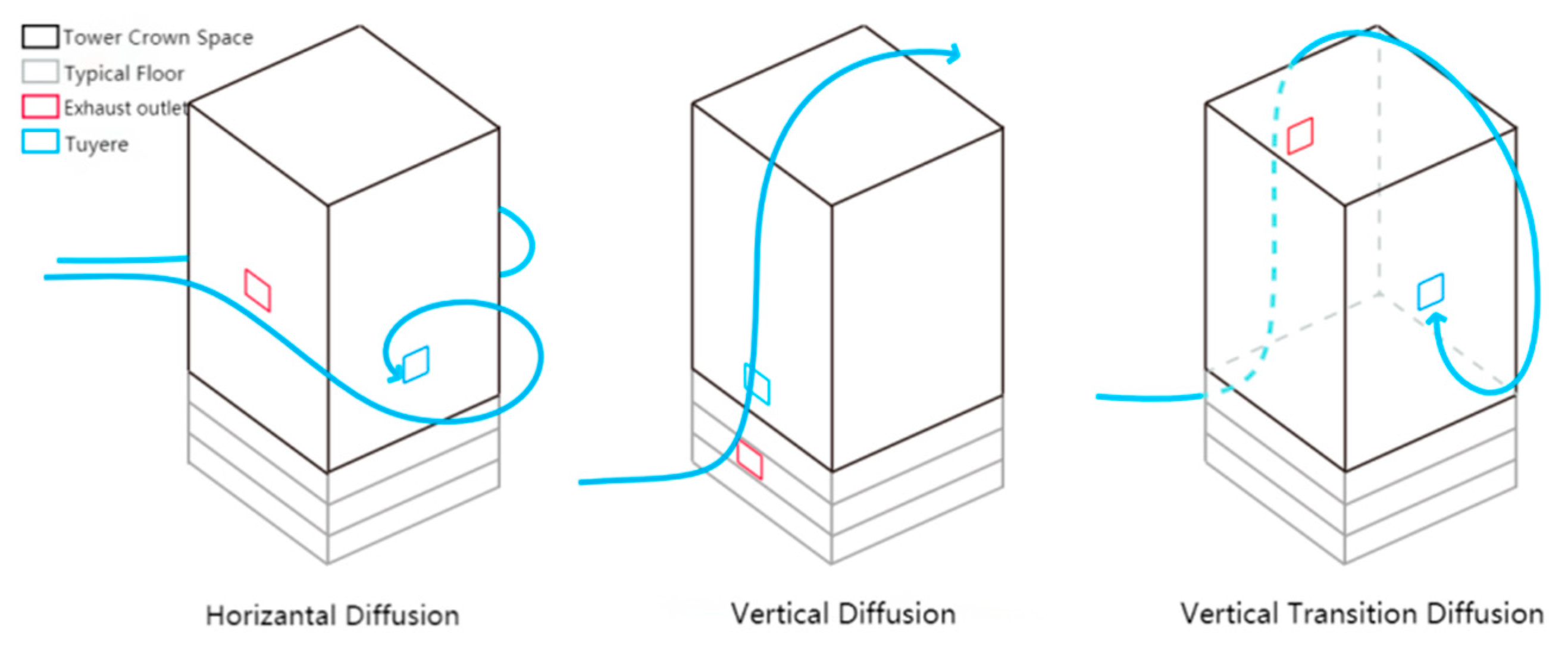
2. Outdoor Airflow Short-Circuiting and External Wind Pressure Texture of Super-High-Rise Tower Crown
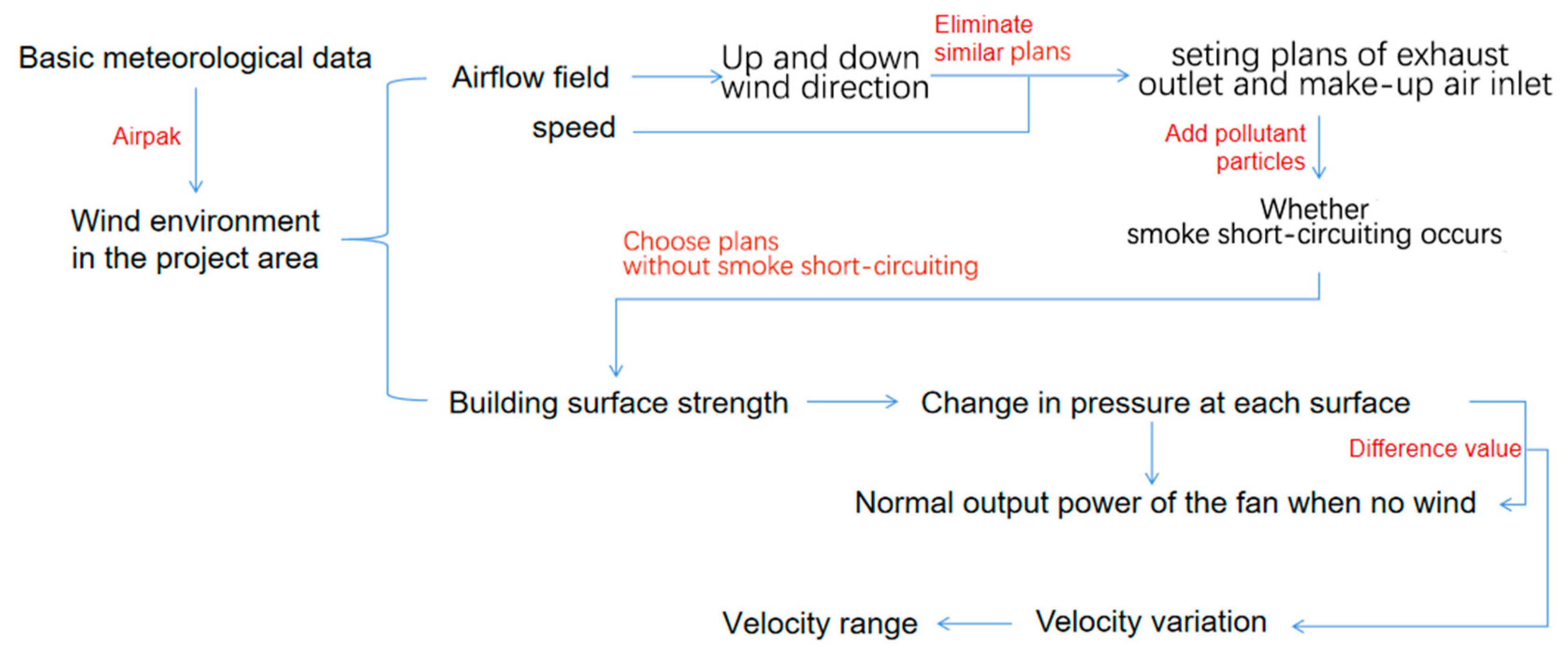
3. Methods
3.1. Introduction to Software
3.2. Comparative Simulation Plans
3.3. Construction of an Abstract Geometric Model
4. Results
4.1. External Wind Environment of Tower Crown Space
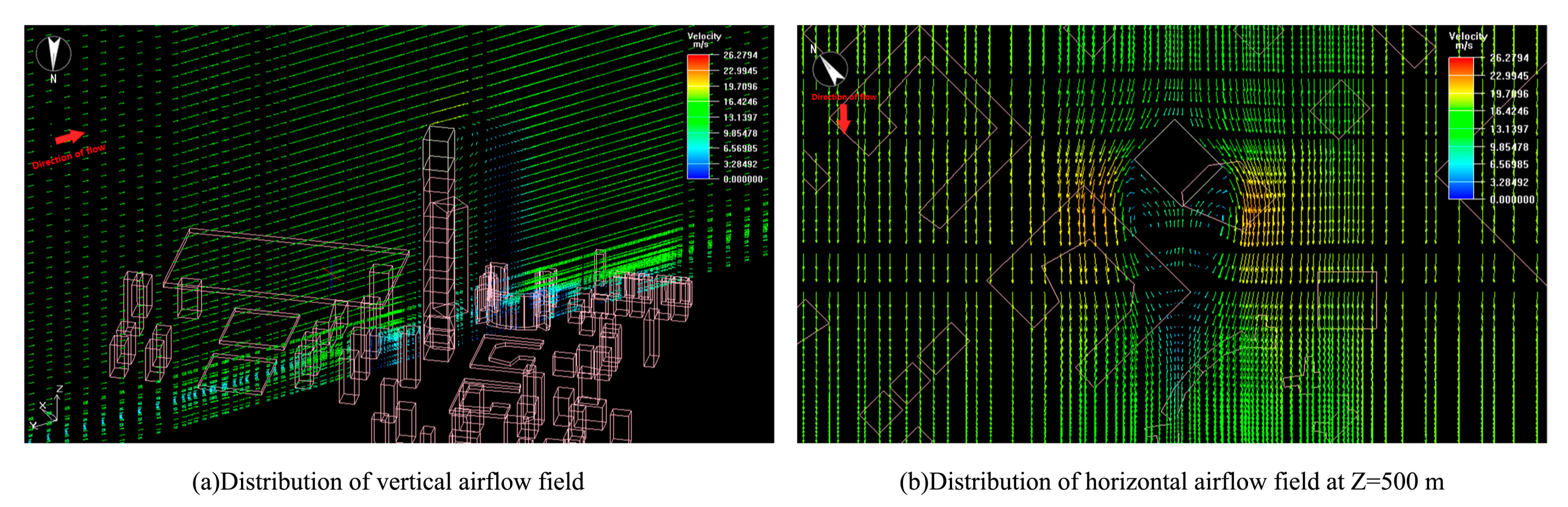
4.1.1. Outdoor Airflow Field
4.1.2. Pressure on Building Surface
4.2. Flowing Rules of Smoke under the Effect of Wind Environment
4.3. Effect of Pressure on Velocity at Make-up Air Inlet and Exhaust Outlet
4.3.1. Airflow and Corrected Velocity of Make-up Air Inlet and Exhaust Outlet under the Effect of Air Pressure
4.3.2. Simulation of Each Plan after Revising Velocity
5. Discussion
5.1. Mechanism of Smoke Flow and Effect of Wind Pressure on Vent Velocity
5.2. Recommendations for Optimized Setting of Exhaust Outlet and Make-Up Air Inlet under the Effect of External Wind Environment
- (1)
- The exhaust outlet and make-up air inlet should be set on opposite sides, with restrictions when set on the same and adjacent sides.
- (2)
- Partial windproof components set up at exhaust outlet and make-up air inlet in the tower crown space make-up air inlet.
5.3. Limitations and Prospects
6. Conclusions
- Considering the short-circuiting of outdoor smoke flow caused by the external wind direction or improper setting of the relative position of the make-up air inlet and the exhaust outlet, we used Airpak simulations to analyze the airflow direction of the outdoor airflow by setting up smoke exhaust vents and supplementary air vents in different directions in the crown space with regard to velocity and particle trajectory. We concluded that the exhaust outlet and make-up air inlet should be set on opposite sides, with restrictions when set on the same and adjacent sides. The setting and orientation plan of a smoke-free short-circuiting was established.
- Because excessive wind pressure on the surface of the vents caused by high wind velocity affects smoke exhaust efficiency, we analyzed a wind gradient with Airpak. We simulated the surface wind pressure of the smoke exhaust outlet and the make-up air inlet in each direction. The velocity of the vents and the surface wind pressure were analyzed, the velocity correction of the fan was performed via calculation, corrected 29.38%, 14.44%, and 11.34% for the make-up air inlet, and corrected 11.5%, 3.46%, 14.95% for the exhaust outlet. We obtained the set velocity ranges of the make-up air inlet and exhaust outlet in the tower crown space.
- The corrected vents were simulated under the external airflow field. We found that most of the vent pressure was uneven under the influence of the airflow field during the operation of the smoke exhaust system, and the local pressure was too high. It is necessary to use local windproof components to reduce the effect of external wind.
Author Contributions
Funding
Institutional Review Board Statement
Informed Consent Statement
Data Availability Statement
Conflicts of Interest
References
- Zheng, C.; Li, Y.; Wu, Y. Pedestrian-level wind environment on outdoor platforms of a thousand-meter-scale megatall building: Sub-configuration experiment and wind comfort assessment. Build. Environ. 2016, 106, 313–326. [Google Scholar] [CrossRef]
- Liu, K.; Wang, Q.; Zhang, W. Analysis of the current situation and common problems of our national defense smoke extraction system. Fire Sci. Technol. 2018, 37, 331–333+336. [Google Scholar]
- Cheng, L. Exploring the maximum allowable smoke exhaust volume of a single smoke vent. HVAC 2020, 50, 82–85+102. [Google Scholar]
- Xin, J. Analysis of the problem of fire smoke exhaust system design and fan selection. HVAC 2017, 47, 27–31+66. [Google Scholar]
- Li, B.; Yang, H.; Zhang, J. Characteristics of smoke exhaust system and selection of smoke exhaust fan. HVAC 2014, 44, 8–12+17. [Google Scholar]
- Tang, S.; Lu, G.; Hu, Z.; Gan, Z. Study on the “short circuit” phenomenon of outdoor smoke flow in buildings. Fire Sci. Technol. 2014, 33, 1019–1021.6. [Google Scholar]
- Fang, Q. Study on the Influence of External Wind Environment on the Design of Smoke Evacuation in Super High-Rise Buildings. Master’s Thesis, Jilin University of Architecture, Changchun, China, 2018. [Google Scholar]
- Li, L. A study on the performance of smoke extraction system in ultra-high atrium based on numerical simulation. Fire Sci. Technol. 2015, 34, 1587–1589. [Google Scholar]
- Hadjisophocleous, G.; Zhou, J. Evaluation of Atrium Smoke Exhaust Make-Up Air Velocity. ASHRAE Trans. 2008, 114, 147–155. [Google Scholar]
- Li, X.F. Influence of make-up air methods on the effectiveness of mechanical smoke extraction in atrium-type large-space buildings. Fire Sci. Technol. 2016, 35, 193–197. [Google Scholar]
- Sun, G. The effect of mechanical make-up air outlet setting height on smoke exhaust effect. Fire Sci. Technol. 2019, 38, 812–814. [Google Scholar]
- Zhou, D.; Wang, J.; He, Y. Numerical Simulation Study of Smoke Exhaust Efficiency in an Atrium. J. Fire Prot. Eng. 2010, 20, 117–142. [Google Scholar] [CrossRef]
- Huang, D.; Zhu, J.; Xia, R.; Li, J. Numerical simulation of the effect of outdoor wind on the smoke motion in the shaft of a high-rise building. Fire Sci. Technol. 2007, 26, 595–598. [Google Scholar]
- Zhang, H.; Chen, J.; Wang, H.; Li, H. Simulation of the effect of natural wind pressure on fire smoke extraction in super high-rise buildings. Fire Sci. Technol. 2018, 37, 180–184. [Google Scholar]
- Song, X. Analysis of design points of tower crown part of super high-rise public buildings below 250 m. Real Estate Guide 2019, 15, 37–38. [Google Scholar] [CrossRef]
- Qu, H. Study on Building Energy Consumption and Thermal Comfort of Ice Rink. Master’s Thesis, North China University of Science and Technology, Tangshan, China, 2021. [Google Scholar]
- Ye, X.; Jiang, X.Y.; Shen, G. Application of Airpak software in the field of airflow organization. Appl. Energy Technol. 2006, 10, 45–47. [Google Scholar]
- Zhang, F.; Ryu, Y. Simulation Study on Indoor Air Distribution and Indoor Humidity Distribution of Three Ventilation Patterns Using Computational Fluid Dynamics. Sustainability 2021, 13, 3630. [Google Scholar] [CrossRef]
- Meteorological Data Room; Meteorological Information Center; China Meteorological Administration. China Building Thermal Environment Analysis Specialized Meteorological Data Set; China Building Industry Press: Beijing, China, 2005; ISBN 7-112-07274-3. [Google Scholar]
- SZJG 30-2009; Shenzhen Green Building Evaluation Code. Shenzhen Bureau of Quality and Technical Supervision: Shenzhen, China; China Construction Industry Press: Shenzhen, China, 2009.
- Hussain, S.; Oosthuizen, P.H.; Kalendar, A. Evaluation of Various Turbulence Models for the Prediction of the Airflow and Temperature Distributions in Atria. Energy Build. 2012, 48, 18–28. [Google Scholar] [CrossRef]
- Lu, C.; Li, Q.; Huang, S.; Zhi, L.; Fu, X. Simulation analysis of wind response of Ping An International Finance Building in Shenzhen. J. Build. Struct. 2012, 33, 1–11. [Google Scholar]
- GB51251-2017; Technical Standards for Smoke Prevention and Exhaust Systems in Buildings (2018 Edition). Ministry of Public Security of the People’s Republic of China: Beijing, China; China Planning Press: Beijing, China, 2018.
- JG/T 14-2010; Development of the People’s Republic of China Ventilation and Air Conditioning Vent. Ministry of Housing and Urban-Rural: Beijing, China; China Standard Publishing House: Beijing, China, 2010.


| Fan | Rotating Speed (r/min) | Fan Flow (m3/h) | Full Pressure (Pa) | Static Pressure (Pa) | Fan Power (KW) |
|---|---|---|---|---|---|
| make-up air fan | 800 | 18,170 | 867 | 763 | 7.5 |
| exhaust fan | 650 | 37,670 | 978 | 804 | 15 |
| Computational Field Size | 4800 m × 6000 m × 1800 m |
| Project building size | 60 m × 60 m × 600 m |
| Tower crown space size | 60 m × 60 m × 88 m |
| Inlet boundary condition | Velocity-inlet |
| Outlet boundary condition | Outflow |
| Surface boundary conditions | No-slip wall |
| Wall boundary condition | No-slip wall |
| Meshing | Hexahedral unstructured mesh |
| Turbulence Model | k-ε two-equation model |
| Wind direction | NE |
| 10 m high wind velocity | 3.4 m/s |
| Ground roughness | 0.33 |
| Boundary layer thickness | 1800 m |
| Specification | Make-Up Air Inlet | Exhaust Outlet | |
|---|---|---|---|
| Position | Size: Length 1 m × Width 0.5 m × 6 (pcs) Wind Velocity: V = 5 m/s | Size: Length 1 m × Width 0.5 m × 6 (pcs) Wind Velocity: V = 10 m/s | |
| Same side | Horizontal | Side 2.5 m left (right) of vertical center line Bottom edge 2 m from the vertical centerline of the facade | Side 2.5 m to the right (left) of the vertical center line Bottom edge 3 m from the vertical centerline of the facade |
| Vertical | Bottom edge 2 m from the vertical centerline of the facade | Bottom edge 8 m from the vertical centerline of the facade | |
| Adjacent side | Bottom edge 2 m from the vertical centerline of the facade | Bottom edge 2 m from the vertical centerline of the facade | |
| Opposite side | Bottom edge 2 m from the vertical centerline of the facade | Bottom edge 2 m from the vertical centerline of the facade | |
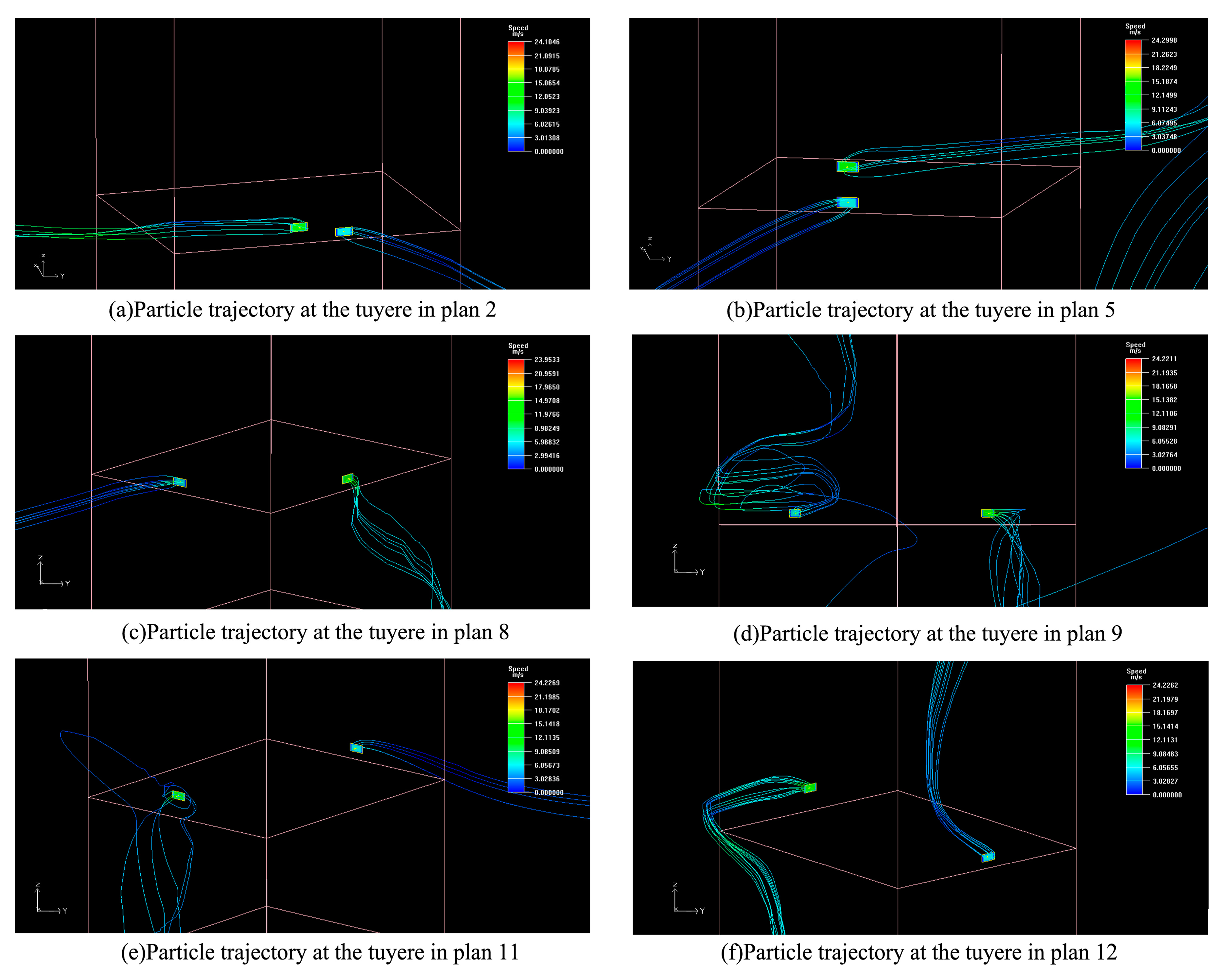
| Position | No. | Diagram | Make-Up Air Inlet Direction | Exhaust Direction | Short-Circuiting | |
|---|---|---|---|---|---|---|
| Same side | Horizontal | 1 |  | After touching the building, the incoming flow rises along the surface and is sucked into the make-up air inlet. | After being discharged, the smoke flows southward over the building surface while also moving upward due to the northeast flow. However, some of the smoke is likely to be sucked indoors. | Likely |
| 2 |  | After the incoming flow touches the building, it moves upward along the surface and is sucked into the make-up air inlet. | The smoke flows westward along the building surface after being discharged, while also moving upward due to the effect of the northeast flow. | × | ||
| 3 |  | A vortex is formed when the incoming flow passes through the building’s corner, and the mixed component of the smoke is sucked into the make-up air inlet. | After being discharged, the smoke rises and is affected by horizontal and vertical eddy currents, with a portion of the smoke being sucked into the make-up air inlet. | √ | ||
| 4 |  | A vortex is formed as the incoming flow passes through the building’s corner, and the smoke is rolled back to the make-up air inlet. | After being discharged, the smoke flows to the south, where it is affected by the horizontal vortex, and a portion of it is rolled back and sucked into the make-up air inlet. | √ | ||
| Vertical | 5 |  | After the incoming flow touches the building, it moves upward along the surface and is sucked into the make-up air inlet. | The smoke flows westward along the building surface after being discharged, while also moving upward due to the impact of the northeast flow. | × | |
| 6 |  | A vertical vortex is formed once the incoming flow passes through the top of the tower crown, the airflow continues downward, and the smoke is sucked into the make-up air inlet. | After being discharged, the smoke travels southwest along the building surface, where it is affected by the vertical eddy current and sucked into the make-up air inlet. | √ | ||
| Adjacent side | 7 |  | A vertical vortex is formed once the incoming flow passes through the top of the tower crown, the airflow continues downward, and the smoke is sucked into the make-up air inlet. | Smoke flows westward when it is released. Some of the smoke is rolled back as a result of the horizontal and vertical eddy currents. It is likely to be sucked up by the make-up air inlet, despite moving downward on the leeward side. | Likely | |
| 8 |  | After the incoming flow touches the building, it moves upward along the surface and is sucked into the make-up air inlet. | After the smoke is discharged, it flows southward over the building surface, while the wind moves downward under the effect of the vertical vortex. | × | ||
| 9 |  | A vertical vortex is formed once the incoming flow passes through the top of the tower crown, the airflow continues downward, and the smoke is sucked into the make-up air inlet, | After the smoke is discharged, it flows southward over the building surface, while the wind moves downward under the effect of the vertical vortex. | × | ||
| 10 |  | Same as plan 9. | Same as plan 9. | × | ||
| Opposite side | 11 |  | After the incoming flow touches the building, it moves upward along the surface and is sucked into the make-up air inlet. | After the smoke is discharged, it flows southward over the building surface, while the wind moves downward under the effect of the vertical vortex. | × | |
| 12 |  | A vertical vortex is formed once the incoming flow passes through the top of the tower crown, the airflow continues downward, and the smoke is sucked into the make-up air inlet. | The smoke travels westward after it is discharged. Part of the smoke is rolled back and flows downward on the leeward side as a result of the horizontal and vertical eddies. | × | ||
| Position | No. | Graphics | Type | Inside and Outside Pressure Difference (pa) | Air Flow (m3/s) | Original Speed(m/s) | Revised Velocity (m/s) | |
|---|---|---|---|---|---|---|---|---|
| Same side | Horizontal | 1 |  | Make-up air inlet | −150 | 6.469 | 5 | 3.531 |
| Exhaust outlet | 150 | 8.844 | 10 | 11.156 | ||||
| Vertical | 2 |  | Make-up air inlet | −150 | 6.469 | 5 | 3.531 | |
| Exhaust outlet | 150 | 8.844 | 10 | 11.156 | ||||
| Adjacent side | 3 |  | Make-up air inlet | −150 | 6.469 | 5 | 3.531 | |
| Exhaust outlet | 70 | 9.654 | 10 | 10.346 | ||||
| 4 |  | Make-up air inlet | −70 | 5.722 | 5 | 4.278 | ||
| Exhaust outlet | 70 | 9.654 | 10 | 10.346 | ||||
| Opposite side | 5 |  | Make-up air inlet | −150 | 6.469 | 5 | 3.531 | |
| Exhaust outlet | 70 | 9.654 | 10 | 10.346 | ||||
| 6 |  | Make-up air inlet | 150 | 4.343 | 5 | 5.657 | ||
| Exhaust outlet | −70 | 11.495 | 10 | 8.505 | ||||
| No. | Pressure Distribution at the Vent | Pressure Distribution at the Exhaust Outlet | Particle Trajectory at the Vent |
|---|---|---|---|
| 1 | 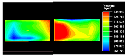 | 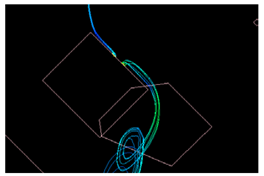 | |
| 2 | 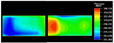 | 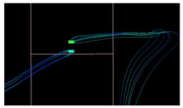 | |
| 3 | 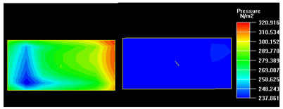 | 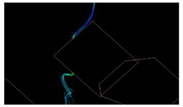 | |
| 4 | 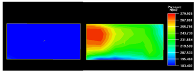 | 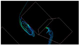 | |
| 5 | 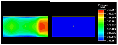 | 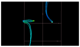 | |
| 6 |  |  | |
Disclaimer/Publisher’s Note: The statements, opinions and data contained in all publications are solely those of the individual author(s) and contributor(s) and not of MDPI and/or the editor(s). MDPI and/or the editor(s) disclaim responsibility for any injury to people or property resulting from any ideas, methods, instructions or products referred to in the content. |
© 2023 by the authors. Licensee MDPI, Basel, Switzerland. This article is an open access article distributed under the terms and conditions of the Creative Commons Attribution (CC BY) license (https://creativecommons.org/licenses/by/4.0/).
Share and Cite
Zhang, T.; Zhou, X.; Zhang, Z.; Qu, F. Research on the Influence Mechanism of Outdoor Wind Environment on Indoor Smoke Exhaust Efficiency in the Super-High-Rise Tower Crown Based on Airpak Simulation. Atmosphere 2023, 14, 1048. https://doi.org/10.3390/atmos14061048
Zhang T, Zhou X, Zhang Z, Qu F. Research on the Influence Mechanism of Outdoor Wind Environment on Indoor Smoke Exhaust Efficiency in the Super-High-Rise Tower Crown Based on Airpak Simulation. Atmosphere. 2023; 14(6):1048. https://doi.org/10.3390/atmos14061048
Chicago/Turabian StyleZhang, Tongtong, Xiaojun Zhou, Zhongsheng Zhang, and Fei Qu. 2023. "Research on the Influence Mechanism of Outdoor Wind Environment on Indoor Smoke Exhaust Efficiency in the Super-High-Rise Tower Crown Based on Airpak Simulation" Atmosphere 14, no. 6: 1048. https://doi.org/10.3390/atmos14061048