Article

CFRP-Strengthening and Long-Term Performance of Fatigue Critical Welds of a Steel Box Girder

1
Empa, Swiss Federal Laboratories for Materials Science and Technology, Laboratory for Mechanical Systems Engineering, Dübendorf CH-8600, Switzerland
2
Carbo-Link AG, Fehraltorf CH-8320, Switzerland
*
Author to whom correspondence should be addressed.
Polymers 2014, 6(2), 443-463; https://doi.org/10.3390/polym6020443
Submission received: 29 November 2013 / Accepted: 28 January 2014 / Published: 11 February 2014
(This article belongs to the Special Issue Selected Papers from "SMAR 2013")

Abstract

:
Empa’s research efforts in the 1990s provided evidence that a considerable increase of the fatigue strength of welded aluminum beams can be achieved by externally bonding pultruded carbon fiber reinforced polymer (CFRP) laminates using rubber-toughened epoxies over the fatigue-weak welding zone on their tensile flange. The reinforcing effect obtained is determined by the stiffness of the unidirectional CFRP laminate which has twice the elastic modulus of aluminum. One can therefore easily follow that an unstressed CFRP laminate reinforcement of welded beams made of steel will not lead to a substantial increase in fatigue strength of the steel structure. This consideration led to the idea of prestressing an external reinforcement of the welded zone. The present investigation describes experimental studies to identify the adhesive system suitable for achieving high creep and fatigue strength of the prestressed CFRP patch. Experimental results (Wöhler-fields) of shear-lap-specimens and welded steel beams reinforced with prestressed CFRP laminates are presented. The paper concludes by presenting a field application, the reinforcement of a steel pendulum by adhesively bonded prestressed CFRP laminates to the tensile flanges of the welded box girder. Inspections carried out periodically on this structure revealed neither prestress losses nor crack initiation after nine years of service.

1. Introduction

Welding is a commonly used joining technique for mechanical and civil engineering metallic structures. These structures sustain not only static but also alternating loads with different amplitudes. Welds represent the weakest elements since fatigue cracks initiate preferentially within the weld or otherwise in its heat affected zone [1]. Several reasons may be responsible for this behavior. Depending on the quality of the weld, one has to consider imperfections such as pores, blowholes, undercuts or lack of fusion. Furthermore in the heat affected zone structural changes of the metal may occur from the welding process which may result in reduced material strength [2]. The large temperature gradients in the vicinity of the weld on the other hand result in residual stresses. Since residual compressive stresses increase the fatigue life of such joints residual tensile stresses reduce the fatigue life. Without heat treatment residual stresses remain in the weld having a maximum magnitude of approximately the yield stress of the material. Since these residual stresses act as static stresses their effects are the same as mean stresses from external loads. One may easily guess, that increased mean stresses significantly reduce the fatigue life of such metallic structural components. External strengthening may therefore have an important structural and economic impact on the service life of welded structures. Empa demonstrated in the 1990s that applying carbon fiber reinforced plastics (CFRP) to aluminum, wood or concrete structures improves the service life up to a factor of 5 to 10 times [3,4,5]. A significant contribution of the strengthening effect may be attributed to the high stiffness ratio in elastic modulus between CFRP-laminates and the base material. Since the stiffness ratio is near 1.0 for steel components a substantial strengthening effect may only be obtained by inducing compressive stresses in the fatigue sensitive zone. This can be achieved by externally bonding prestressed CFRP-laminates. The prestressed reinforcement method and the results from experimental fatigue tests on reinforced welded steel beams are presented and discussed in this paper. A field application consisting of the reinforcement of a steel pendulum by adhesively bonded prestressed CFRP laminates is presented at the end of the paper and proves the structural durability of the method.
A literature survey revealed several studies in the last decade on steel structures strengthened with non-prestressed Fiber Reinforced Polymer (FRP) laminates, see e.g., [6,7,8,9,10,11,12,13,14]; Schnerch et al. [15] even proposed design rules and installation procedures for strengthening of steel bridges with FRP strips, focusing on high modulus CFRP laminates. The increase of the fatigue resistance of steel structures by externally bonding non-prestressed CFRP laminates has been less studied [8,9,10,11] and the fatigue life increases reported are limited to a factor of 3.4 for normal modulus CFRP laminates (E11 < 200 GPa). Little research has been reported on the use of prestressed CFRP laminates for strengthening steel structures [16,17,18,19]. Bassetti et al. [16,17] conducted both small-scale tests and full-scale tests on old riveted girders reinforced with prestressed CFRP laminates and showed that depending on the ratio of the applied load, the reinforcement ratio, and the prestressing level, the use of CFRP laminates can lead to an increase in fatigue life of more than 16 times. Experiments by Täljsten et al. [18] showed that it is feasible to increase the fatigue life almost four times compared to a reference specimen reinforced with non-prestressed laminates. When prestressing the laminates the crack growth was completely stopped even though the prestressing level was rather low. Furthermore, Huawen et al. [19] quantified the potential for increasing the fatigue resistance of pre-cracked steel plates through strengthening with externally bonded prestressed CFRP laminates and concluded that the prestress significantly prolongs the remaining fatigue life of reinforced double-edge notched tensile specimens as the cyclic stress and stress ratio are reduced compared to non prestressed CFRP reinforcements. Ghafoori et al. [20] recently proposed a prestressed unbonded CFRP reinforcement system to strengthen cracked steel beams. A bulky mechanical clamping system was used to anchor and press the CFRP plate against the tensile flange of an I-beam. The proposed prestressed reinforcement can be used as an alternative to prestressed and bonded CFRP plates, particularly when high ambient temperatures, moisture, water and high cycle fatigue regimes endanger the adhesive between the CFRP and the metal. The fatigue performance of pre-notched beams strengthened by the prestressed unbonded system and the remaining load-carrying capacity were satisfactory while the failure mode in the final quasi-static bending tests was questionable: The CFRP plate slipped in the mechanical anchoring system while the notched beams strengthened by an externally epoxy-bonded and prestressed CFRP laminate reached tensile failure of the laminate at ultimate. Similarly the open and crucial point in the investigation by Huawen et al. [19] is the finding of a simple solution for the anchorage of the adhesively bonded prestressed CFRP laminates to the steel structure, which were clamped at their ends by steel plates connected with high-strength prestressed bolts.
Hence applied prestressed laminates will introduce residual compressive stresses into the welds that superimpose the oscillating stresses [21]. Using an optimized prestress level, the oscillating stresses may be shifted completely to compression. Due to the mean stress influence [1] crack initiation will then need many more bending cycles and potential cracks would no longer open and grow under service loads.

2. Specimens and Materials

The current investigation utilized cold rolled steel beams made of standard steel, type S355J2H (St 52-3) according to standard EN 10025 [22] having a square shaped cell cross section (50 mm× 50 mm × 4 mm) and a length of 1000 mm (Rp0.2 > 355 MPa, Rm = 510–680 MPa, A > 20%). In the middle of the beam a cut was milled in the lateral direction having a width of 3 mm and a depth of approximately 5 mm. Using DMO-IG welding rods the cut was TIG welded and the raised welding bead (Figure 1) was grinded as shown in Figure 2.
Figure 1. Raised welding bead [23].
Polymers 06 00443 g001
Figure 2. Weld after grinding [23].
Polymers 06 00443 g002
Pultruded unidirectionally fiber reinforced CFRP laminates of type Toray T300 and Toray T700S having rectangular cross sections of 40 mm × 1 mm were bonded to reinforce the welding zone of the beam. The properties according to Table 1 apply for the CFRP laminates.
Table 1. Average of mechanical properties of carbon fiber reinforced polymer (CFRP) laminates (manufacturer).
PropertiesToray T300Toray T700S
Fiber volume Vf (%)69.772.5
Tensile strength Rm (MPa)20002950
Young’s modulus, long, E11 (GPa)147.5163.6
Strain at failure εf (%)1.361.8
Static tensile and tensile creep tests were carried out by using lap-shear-specimens on the basis of ASTM D5868 [24] to characterize the adhesive bond between laminate and steel (Figure 3). Toray T300 laminates were used for lap-shear specimens. The flat steel plate consisted of standard steel, type S235JR (St 37-3, Rp0.2 > 235 MPa, Rm = 340–470 MPa, strain at failure A > 26%).
Figure 3. Lap-shear-specimen for shear, fatigue and creep tests [25].
Polymers 06 00443 g003
Since preliminary fatigue investigations [23] revealed, that the adhesive system represents the strength limiting component of reinforced welded beams, which was also confirmed by Jones and Civjan [9], a selection of adhesive systems has been considered in the present investigation. The selection criteria were high shear strength, an elastic modulus of 1–2 GPa (except for the phenolic resin) as well as availability and simple handling (cartridge or film, hence the avoidance of mixing chemical components by hand was a prerequisite).
Table 2 shows a summary of the chosen adhesives and their properties, as provided by the manufacturers. Fatigue tests as well as long term strain measurements on CFRP prestressed welded beams showed significant creep effects that resulted in the loss of pretension of the CFRP laminate [25].
Table 2. Summary of the investigated adhesive systems [25].
AdhesivePolyure-thane 1Epoxy resin 1Epoxy resin 2Phenol resinPolyure-thane 2Meth-acrylateEpoxy resin 3Epoxy resin 4Epoxy resin 5Epoxy resin 6
Short cutPu 1Er 1Er 2PhrPu 2MaEr 3Er 4Er 5Er 6
Hardening conditions24 h2 h, 60 °C 7 days, RT30 min >140 °C120 to 250 °C8 h, 80 °C48 h, RT60 min 120 °C60 min 120 °C30 min 100 °C30–60 min 100 °C
Hardening pressure2 bar1.7–3.4 bar1.7–3.4 bar
Young’s modulus [MPa]717001500~300 9651718
Tensile strength [MPa]82935 829 2832
Tensile shear strength [MPa]5 (t = 2.0 mm)18–21 (t = 1.3 mm)29 (t = 1.5 mm)>12163034.5 20–2537
Strain at failure [%]230910 9540 63
Nature of productcartridgecartridgecartridgefilm (4 cm)cartridgecartridgefilmfilmcartridgecartridge
ViscosityA: 30–45 g/min B: 55–80 g/minA: 142 Pas B: 1.6 Pas35 Pas paste-likepaste-like paste-likepaste-like
Therefore main efforts have been put towards characterizing adhesive systems in terms of static tensile strength and especially of tensile creep behavior using lap-shear specimens. The curing state of the adhesives was of particular interest as it has significant influence on the adhesive creep behavior. Even though the recommendations of the manufacturers have been considered, additional DSC-analyses (differential scanning calorimetry) were carried out on the adhesive systems to assess their hardening state.

3. Experimental Section

Static single-lap shear tests were performed on a 200 kN universal test machine in order to determine the ultimate tensile shear strength of the adhesives. Lap-shear specimens (Figure 3) were loaded by applying a constant displacement rate of 1 mm/min. The elongation of the specimens was measured by monitoring the displacement of the machine's cross head.
These lap-shear specimens have been used as well for shear creep tests. Three tensile creep testing machines having a load capacity of 7500 N were used.
Since static properties do not allow drawing conclusions about the bond behaviour under fatigue loading, lap-shear specimens were also used for tensile fatigue tests. Four servo hydraulic test facilities were used to perform these tests applying constant amplitude loading at a frequency of f = 10 Hz. The stress ratio R was kept constant for all tests having a value of R = σlowup = 0.6. During the fatigue loading the strain behaviour of the lap joint was monitored using a laser displacement sensor. By monitoring periodically the maximum and minimum strain values of single load cycles the creep behaviour of the lap joint could be assessed during the tests.
Damages of reinforced components often initiate at the ends of the CFRP-laminate since the change of stiffness causes stress peaks, see e.g., Stratford and Cadei [26]. The lap shear specimen does of course not represent the reinforcing configuration in a practical application. The comparison of different adhesive systems was the primary goal for performing fatigue tests using this specimen type. The maximum change in stiffness is located at the end of the steel plate. At this location a maximum shear stress peak occurs. As a consequence, delamination or failure of the adhesive system may be expected to start from this location.
Most practical engineering components containing a fatigue critical weld are stressed by tension or bending loads respectively. Therefore the weld of a cold rolled steel beam shown in Figure 2 was reinforced by bonding a prestressed CFRP-laminate of type Toray T700S (Table 1) having a bond length of 300 mm. Different adhesives were studied and in all specimens a light glass fiber fabric (thickness tf = 0.22 mm, specific weight ρ = 225 g/m2) was used to define the thickness of the adhesive layer to be t ≈ 0.2 ± 0.1 mm. As noted by Liu et al. [11] the placing of glass fibre fabrics between the CFRP laminate and the steel beam during bonding gives the additional benefit of preventing galvanic corrosion. The prestressing level, an important parameter for this kind of reinforcement, was fixed at this state of the investigation at 600 MPa.
A four-point-bending setup (Figure 3) was chosen for loading the reinforced steel beams in fatigue. As discussed before, the initiation of damage may be expected at the ends of the reinforcing laminate. In order to obtain a good performance, a reinforcing layout may be chosen where laminate ends are located in weakly stressed regions. Since in many practical applications the laminate ends may be highly stressed, the four-point-bending setup chosen appears appropriate to simulate the latter situation. For this configuration the ends of the reinforcing prestressed CFRP laminate are exposed to the same constant bending moment present between the inner load introduction points.
Figure 4. Four-point-bending setup with prestressed CFRP laminate on the beam’s tension flange.
Polymers 06 00443 g004
Finite element analysis [23] of a reinforced beam (half model) clearly shows a longitudinal tensile stress peak in the steel beam at the end of the laminate. The welded zone, as intended, is under compression. The large stress gradient in the steel beam causes the reinforcement’s adhesive system to sustain high shear stress peaks at the laminate’s end. Structural adhesive systems usually need raised temperatures for complete curing (normally T = 80–140 °C, combined with adjusted curing time according to Table 2). The difference of the thermal expansion coefficient in the longitudinal direction of the unidirectional reinforced CFRP-laminate (αCFRP ≈ 0 K−1) with the one of steel (αSt ≈ 11 × 10−6 K−1) causes prestress losses when cooling the reinforced steel beam from the adhesive’s curing temperature to room temperature. The fatigue life of the welded beam will therefore be reduced because of higher mean stresses in the heat affected zone.

4. Results and Discussion

From the static tests the tensile shear strength values of the adhesive systems indicate no clear winner (Figure 5). It may be expected, that when changing the adhesive’s curing conditions the single-lap shear tests will result in modified shear strength values. When comparing static shear results with creep and fatigue behavior, one can easily conclude that the static strength value is not representative for estimating the bond quality. Although the epoxy resin “Er 4” shows a shear strength only in the midfield of the static shear results given in Figure 5, its creep behavior (Figure 6) and fatigue strength are excellent (Figure 7).
Figure 5. Static single-lap tensile shear strength of different adhesive systems (averages and standard deviations of two specimens) [25].
Polymers 06 00443 g005
Figure 6. Creep behavior of different adhesives relative to bonding length (film thickness t ≈ 0.2 ± 0.1 mm, τm = 4.1 MPa) [25].
Polymers 06 00443 g006
On the other hand the “Ma” adhesive which was manufactured at room temperature revealed the top lap-shear strength result (Figure 5), but shows significant creep behaviour during a test period of 400 h (Figure 6). The corresponding fatigue strength is in the middle of all the tested systems (Figure 7). From the creep test results (Figure 6) it appears obvious, that phenolic resin, polyuretane and methacrylate systems may not be suitable for reinforcing applications using prestressed CFRP-laminates. Each of these systems would lead to a loss of the prestress of the laminate due to creep effects within the adhesive layer. This can also be recognized from their fatigue performance in Figure 7, where most of these systems are located on the lower bound of the adhesive’s Wöhler-field.
Figure 7. Fatigue lives of single lap-shear-specimen bonded with different adhesive systems [25].
Polymers 06 00443 g007
The investigations on the welded beams reinforced with the prestressed CFRP laminate in four-point bending using adhesives “Er 6”, “Er 1” and “Er 4” as well as “Ma” [27,28] indicate an increase in fatigue life by a maximum factor of two times compared to unreinforced welded beams (Figure 8). In all specimens delamination in the adhesive layer starting from the laminate ends is responsible for this moderate increase of fatigue life. However a subsequently performed fatigue test on a reinforced beam with adhesive “Er 1” having the laminate ends in lowly stressed regions (at the beam ends but just before the supports in Figure 4) show a significant increase in fatigue life by a factor of more than 10 times (Figure 8).
The main conclusion of this experimental comparative study on adhesives’ performance for fatigue strengthening by externally bonding prestressed CFRP laminates is that epoxy adhesives are the most effective with respect to the fatigue resistance of the reinforced welded steel beams discussed above (Figure 8, adhesives Er 1 and Er 6). Therefore the authors have chosen an epoxy adhesive for the field application described in the following.

5. Field Application

An artwork pendulum in the atrium of an office building was made of a welded steel DD11 (StW22) box girder having a length of approximate 12 m. The pendulum performs an oscillation of ±60° having a period of 24 s (Figure 9). Assuming approximate ten hours of service each day, a total of 390,000 oscillations result every year (oscillation frequency 0.042 Hz). The steel box girder consists of four sections as indicated in Figure 9. Each section is made up of two web plates and two tension/compression flanges providing a rectangular tube. Longitudinal fillet-welds, located on the outer side of the tube’s edges, connect the web plates and tension/compression flanges. The lower and intermediate sections have a tapered shape in order to minimize dead load. The lower section has a length of 3.665 m. It carries two TV-monitors of 80 kg mass each on its lower end (Figure 9). The intermediate section has a length of 2.985 m. The lower and intermediate sections were connected by circumferential butt welds, denoted as lower joint in Figure 9. The short section next to the intermediate section contains the pivot driving devices. It has a length of 2.09 m. Four T-shaped beams are connected to the pivot drive, two on each side (Figure 10). These four beams are fixed to the atrium’s ceiling, which carries the artwork pendulum. The intermediate section was originally connected to the pivot drive section by a total of 12 HV-screws (Figure 10). The top segment with a length of 3 m contains the balancing weight of the pendulum. It was originally connected to the pivot drive section by 12 HV-screws as well (Figure 10).
Figure 8. Fatigue lives of lap-shear-specimen bonded with different adhesive systems [28].
Polymers 06 00443 g008
Figure 9. Artwork pendulum.
Polymers 06 00443 g009
Figure 10. Pivot drive section with originally designed middle and upper joint.
Polymers 06 00443 g010
After a few months of service in year 2000 the head of a screw, connecting the intermediate to the pivot drive section of the steel box girder, broke. As a consequence, the upper and middle joints were butt-welded. However, after another 19 months of service (approximate 620,000 oscillations) significant fatigue cracks developed in the heat-affected zones of the box welds at the lower and middle joint respectively (Figure 11). Moreover, detailed inspections revealed a low manufacturing quality of the welds.
Figure 11. Fatigue cracks in welds after 19 months of service.
Polymers 06 00443 g011
A fatigue strength analysis by Koller [29] based on the FKM-Guideline [1] of the welds concluded that the oscillating bending stresses would initiate fatigue cracks (that would grow some time till separation of the cross section) whatever quality the welds are manufactured. Conventional strengthening techniques that add steel plates by adhesive bonding, riveting, bolting, welding or clamping [30] were no option. Further structural investigations by Koller [29] showed, that the nominal alternating bending stresses increase due to stress concentrations at notches caused by riveting, bolting or welding. When using steel plates, the dead load of the pendulum would significantly increase since the balancing weight needs an adjustment as well. Several repair options were evaluated with a repair cost minimization, a considerable increase in durability and the visual appearance of the strengthened artwork in mind. It was finally decided to repair the pendulum by local reinforcement of the welds by using high-strength CFRP laminates, that were adhesively bonded in a prestressed state (Figure 12).
Figure 12. Strengthening principle of welds in the steel box girder, details at middle joint.
Polymers 06 00443 g012

5.1. Design of the Reinforcement by Finite Element Analysis

Since the pendulum performs an oscillating movement of ±60° in service, the bending stresses at the maximum loaded welds at the middle joint (Figure 12) vary from +40.2 to −40.2 MPa representing a stress ratio of R = −1. In order to design a prestressed CFRP reinforcement for a welded steel box girder, a finite element model (static, linear-elastic stress analysis) was set up that had three 1 m prestressed CFRP laminates applied on both tension/compression flanges (described in detail in Koller et al. [31]). The finite element analysis showed that a prestress load of 45 kN for a 50 mm × 1 mm thick unidirectional CFRP laminate is sufficient because the residual compressive stress in the critical weld is σres ≤ −45 MPa, independent of the laminate type. Two commercially available undirectionally reinforced carbon fibre epoxy laminate types were taken into consideration: Carbodur S512 by Sika [32] with E11 = 165 GPa and Toray M46J with E11 = 305 GPa by Toray [33]. Despite of the slightly larger shear stress maximum in the bonding agent at the CFRP laminate ends and the slightly larger adhesive-yield region at laminate ends [31], the laminate choice should tend to lower stiffness for not losing too much prestress in cases when relaxation processes in the epoxy adhesive would take place (e.g., at higher service temperatures which approach the Tg of the epoxy adhesive Scotch Weld® 9323 B/A [34] used being 80 °C). Furthermore the strength capacity of thinner laminates is used more efficiently at a lower price. Hence the thinnest laminate available having a thickness of t = 1.0 mm was chosen for strengthening the steel box girder.

5.2. Experimental Verification of the Prestressed Reinforcement Design

An experimental verification of the strength behavior under fatigue loading was mandatory, since limited experience exists for strengthening steel structures using adhesively bonded prestressed CFRP laminates (see e.g., [16,17]). As it was too expensive to test the real steel box girder, the same company that had delivered the pendulum manufactured a smaller sized specimen (2:5 in scale) containing a circumferential (butt) weld. Material and welding process were identical to the original steel box girder.
The laboratory experiment showed that the downscaled and CFRP reinforced girder specimen withstood 5 million bending load cycles (oscillation movements at 3.5 Hz) at the same stress amplitude at the weld as the pendulum girder (R = −1) without failure [31]. Five million oscillation movements of the artwork pendulum represent a life time period of approximate 13 years. This finding, the experimental assessment of the absence of prestress losses over five million load cycles and a remaining load carrying capacity of over 150% of the maximum service moment after additional 2.22 million load cycles [31] were decisive for the implementation of the presented strengthening method on the full-scale artwork pendulum.

5.3. Strengthening and Monitoring the Artwork Pendulum

After demounting, the pendulum was delivered to Carbo-Link GmbH of Fehraltorf, Switzerland which carried out the strengthening of the steel box girder. The locations of the three butt welds in the pendulum are shown in Figure 13 and Figure 14. Visual inspections revealed transverse cracks having considerable length (up to 190 mm) in all three butt welds (Figure 11). A fatigue life of approximate one year of service was calculated based on the FKM-Guideline [1]. The cracks found in the butt welds as well as the reported service period of 19 months confirmed this prediction for the fatigue life.
The CFRP strengthening of the steel box girder performed by Carbo-Link GmbH included the following steps:
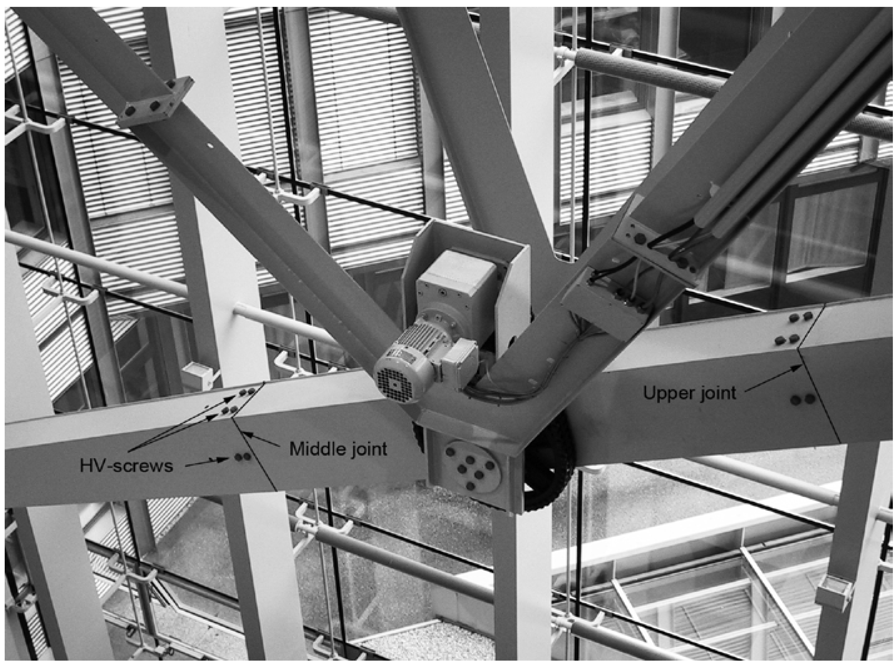
  • Grinding of all transverse butt welds of upper, middle and lower joint.
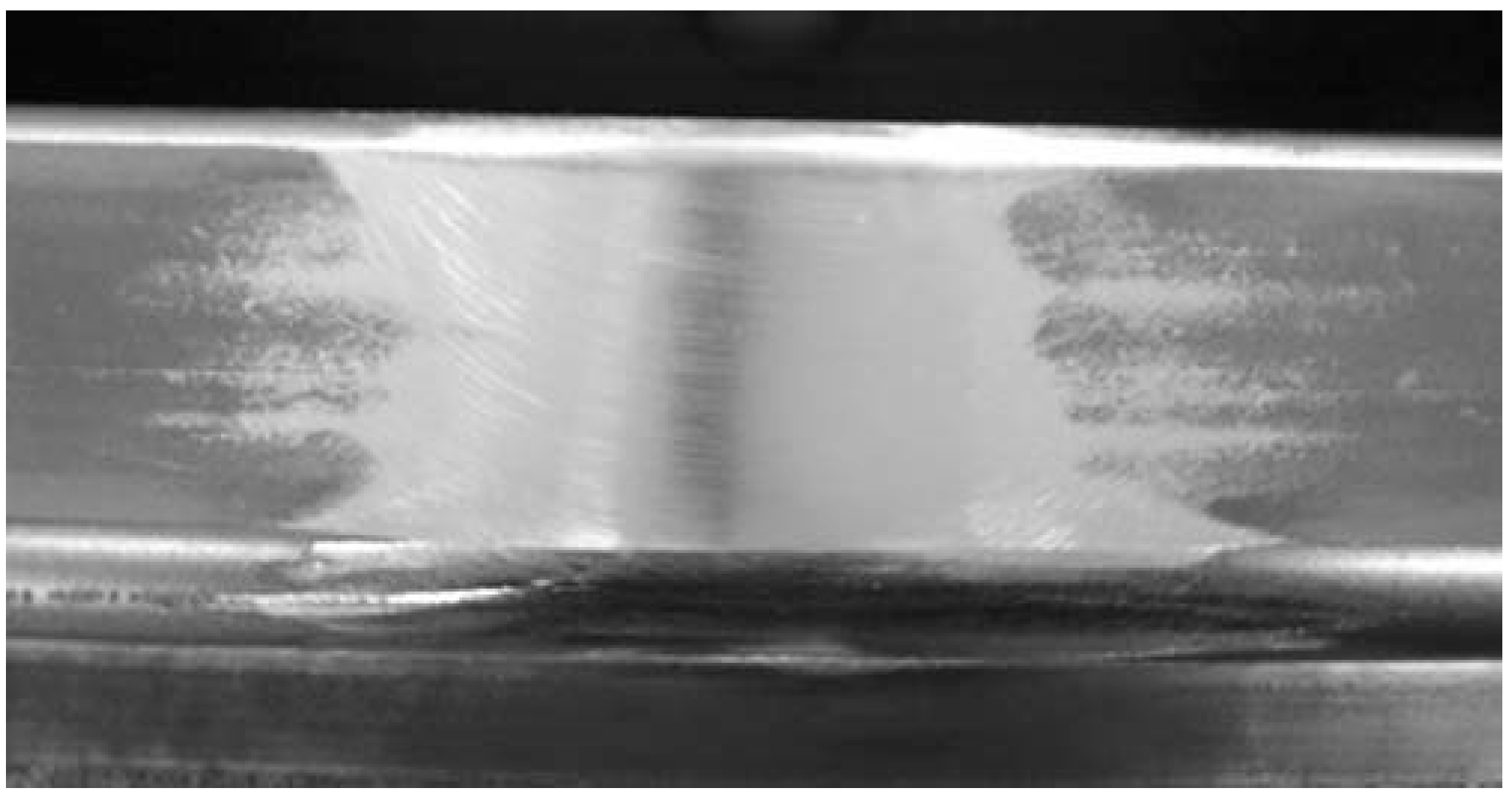
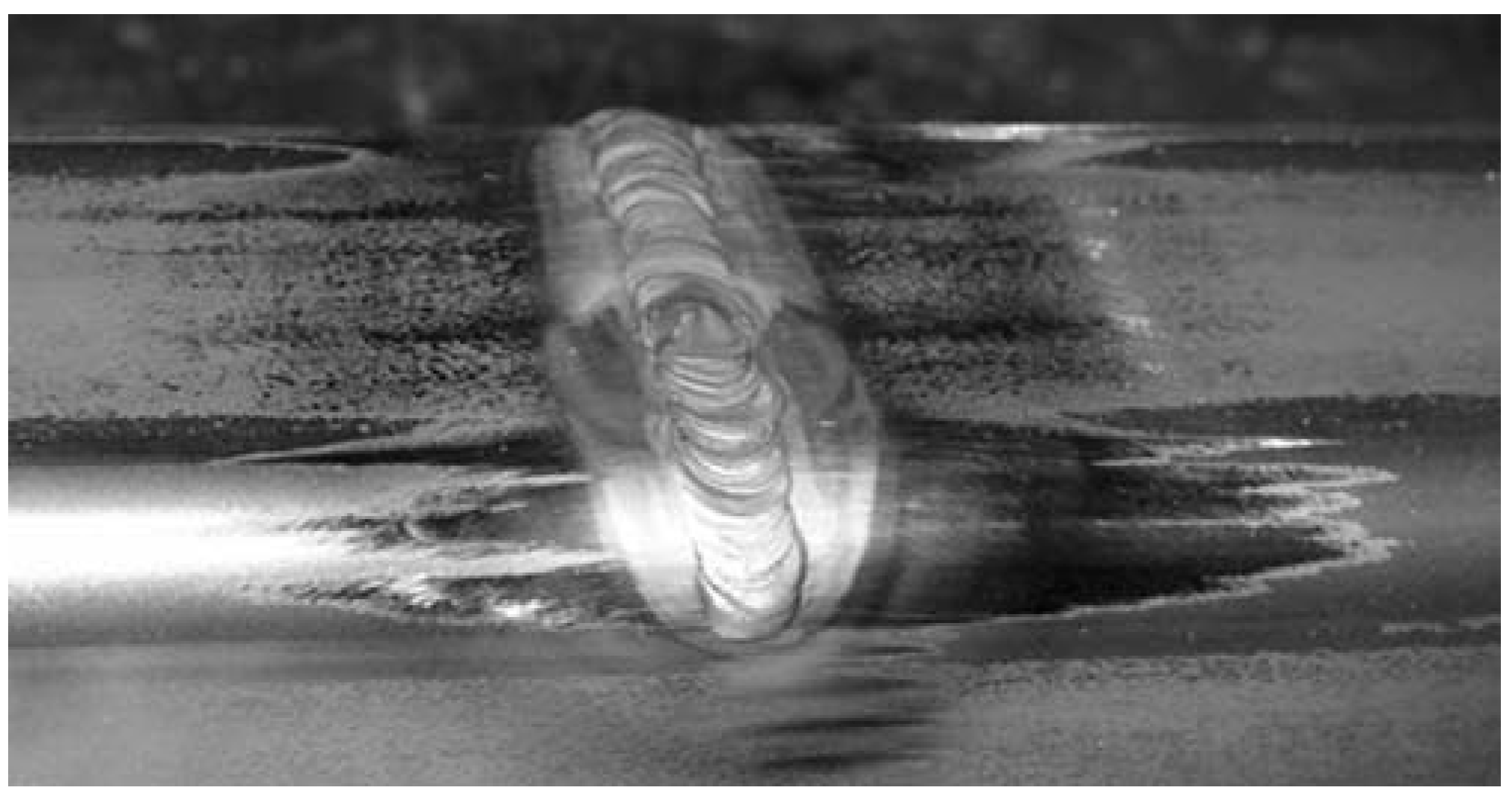
  • Renewing of the butt welds of all joints along the circumference by inert MAG welding using a S235 welding rod (D = 5 mm).
  • Removal of all screws at the upper and middle joints.
  • Removal of the coating on each flange in the range from the upper to the lower joint.
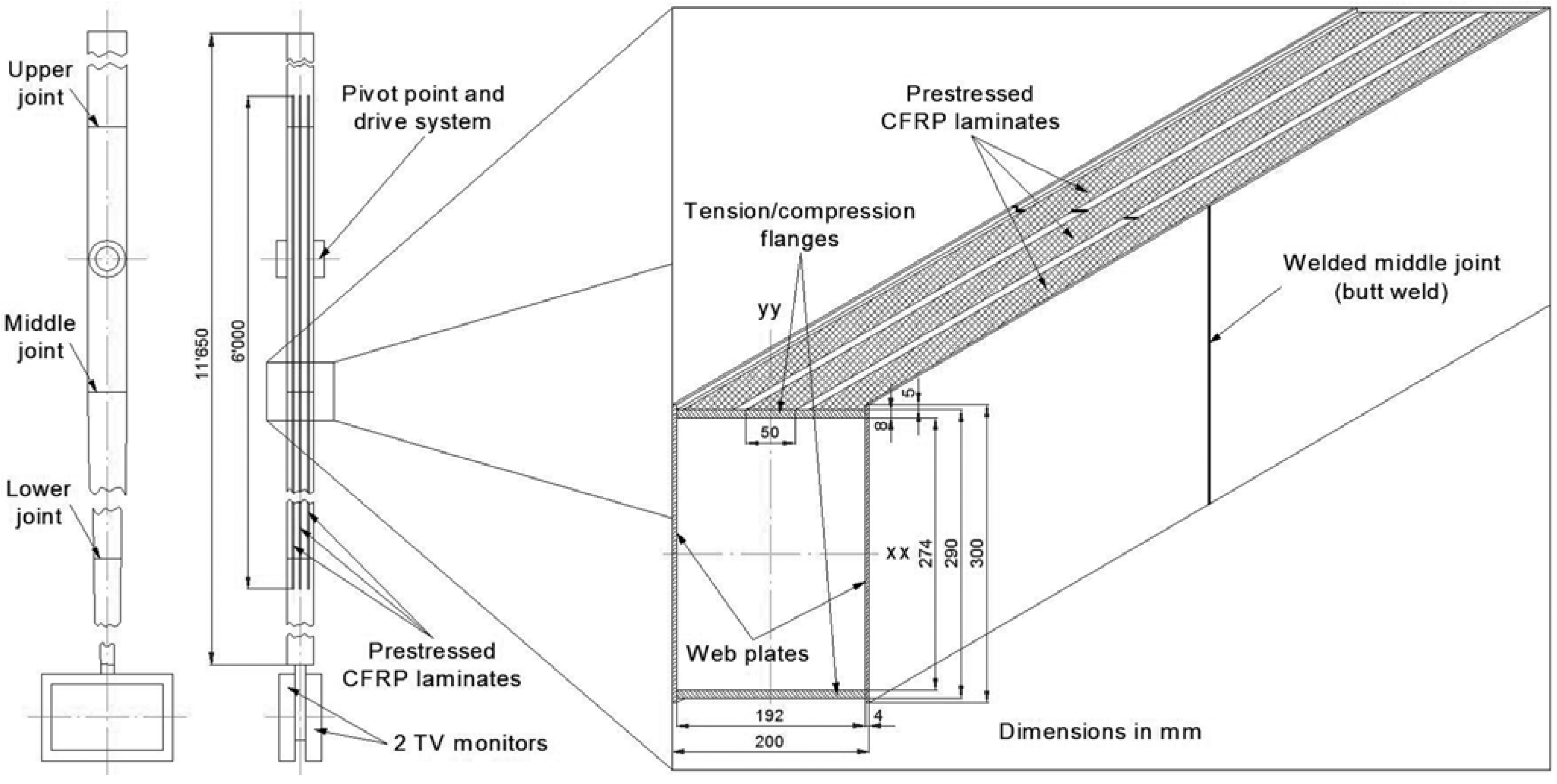
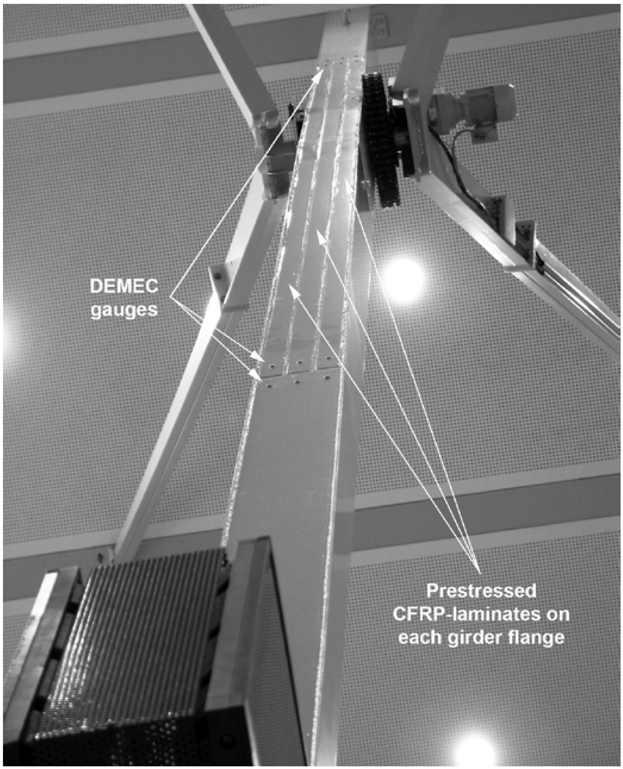
  • Application of three prestressed CFRP laminates (Carbodur S512 grinded on both sides, Fpt = 45 kN, w = 50 mm, s = 1 mm, E11 = 165,000 MPa) on each girder flange following the application procedure described in Meier et al. [5]. A glass fiber fabric (thickness tf = 0.22 mm, specific weight ρ = 225 g/m2) was put between steel girder and CFRP laminates in order to have an electrically insulating layer as well as to define the adhesive layer's thickness. Scotch-Weld epoxy adhesive 9323 B/A [34] was used to bond the prestressed CFRP laminates onto the steel box girder. The application of the prestressed CFRP laminates followed the same procedure used for strengthening the laboratory girder specimen.
  • Application of a new color coating.
  • Transporting the reinforced pendulum to the owner.
  • Mounting of the artwork pendulum.
  • Recommissioning of the artwork pendulum on 14 June 2004 (Figure 13).
Figure 13. Six prestressed CFRP laminates on the flanges of the artwork pendulum.
Polymers 06 00443 g013
In order to monitor the behavior of the strengthened artwork pendulum (Figure 13), periodical inspections were agreed to take place. Besides all the bolt connections, the circumferential butt welds and the condition of the CFRP laminates are inspected periodically every year. In this period the pendulum performs approximate 390,000 oscillation movements. The inspections take place on-site at the not dismantled, vertically oriented steel box girder. A moving working platform is needed to reach all inspection points.
The butt welds (Figure 14) are inspected visually using a binocular eyepiece having a magnification factor of 10. The minimum detectable crack length using this method is ±0.1 mm. With an electric LED-torch the heat affected zones of the welds are illuminated. Special attention is given to the locations of the three girder joints. In each case the four edges were carefully inspected. After nine years of service no cracks were detected.
Figure 14. Location and denomination of butt welds (entrance/yard side) and prestress measuring points at CFRP laminate ends (reception/foyer side).
Polymers 06 00443 g014
The inspection of the CFRP laminate bonding is performed by smoothly knocking on the laminate surface using a coin. An intact bond will respond by a clear sound, a damaged one by a dull sound. No delamination could be detected by this tapping test after nine years of service.
Measuring the displacements between two DEMEC gauges, each 100 mm apart from the laminate end, was used to monitor the prestress state of the CFRP laminates. One point is mounted on the laminate, the other one on the flange of the steel box girder (Figure 13 and Figure 14). In case of a prestress loss (creep of the adhesive layer) the laminates would contract and hence the distance of the DEMEC gauges would increase. These distances are measured by using a precise displacement-measuring device (type: “Deformeter”; accuracy: ±0.001 mm; basis length: 200 mm). Spacing measurements carried out in August 2004 are considered as reference values. For all subsequent measurements the changes are evaluated that give an indication on the variation of the prestress.
Figure 14 shows the changes in measuring point spacing for all twelve monitored laminate ends (six on each girder flange) as a function of the number of performed oscillations.
As can be noted from Figure 15 the distance changes are varying in positive and negative direction around the origin, which represents the reference measurement. Especially negative changes would stand for increasing prestress. However, increasing prestress may result only from temperature-based expansion of the steel box girder (coefficient of thermal expansion CTE for CFRP in fiber direction: αCFRP = 0 K−1, steel: αSt = 12 × 10−6 K−1). Positive as well as negative changes are of the same magnitude. Since the artwork pendulum is mounted in an entrance hall with a glass facade, temperatures may vary from 32 °C in summer to 16 °C in wintertime. Hence temperature variations of ±8 °C cause thermal expansions of the steel girder of ±0.02 mm between DEMEC gauges.
Figure 15. Spacing variation of DEMEC gauge as a function of the number of oscillations.
Polymers 06 00443 g015
Furthermore it has to be mentioned that measurements using a Deformeter take place under hindered conditions. Since a moderate contact pressure is needed to perform the measurements, the pendulum may draw aside and measurement errors in a range of ±0.02 mm were assessed on site. Hence, all measurement results denote that the prestress level variation remains in the range of normal temperature variation and measurement uncertainties, respectively. From the measurement results scattering around the reference value (Figure 15) one concludes, that no loss of prestress occurred in the six CFRP laminates within the past operation time of nine years.

6. Conclusions

The welded steel box girder of the artwork pendulum was dismantled, all welds renewed and the two tension/compression flanges strengthened by three prestressed CFRP laminates in the vicinity of the maximum bending moment. The laminates having a length of 6 m and a cross section of 50 mm × 1 mm have been prestressed at 900 MPa (45 kN each laminate). Hence the resulting nominal stresses in service (bending superposed to compressive stresses) remain throughout in the compressive region. After repainting the pendulum, the strengthening is hardly visible to the naked eye, which was an obvious criterion for the artwork. After nine years of service and 3.2 million oscillations, regular inspections of the strengthened pendulum have revealed neither indication of prestress loss nor delamination, and no initiated fatigue cracks were found.
To date, the reached number of oscillations represents an increase in fatigue lifetime by a factor of over five compared to the welded, not reinforced pendulum girder. This factor is expected to increase in the future. For a scaled girder specimen a factor of eight was obtained from a laboratory fatigue test [31]. Hence the strengthening method appears very promising in order to reach the aimed fatigue lifetime of at least ten years without development of significant crack length.
However, the successful strengthening of this steel member bases on favorable boundary conditions:
  • The long-term behavior of adhesively bonded joints is influenced by humidity and/or liquid water resulting in a time-dependent deterioration [35]. Cohesive or adhesive-type failures may result. The artwork pendulum is mounted in an entrance hall. Compared to outdoor service, limited temperature variations (16 °C ≤ T ≤ 32 °C) as well as moisture variations (30% ≤ rH ≤ 60%) occur during service of the pendulum. Large variations of environmental conditions may cause increased aging of the bonding layer over time and therefore may have negative influences on the strengthening (debonding and/or prestress loss) which were not observed in the present application. Beside the more or less stable environmental conditions of the entrance hall, the applied color coating after strengthening acts as a supplementary protection.
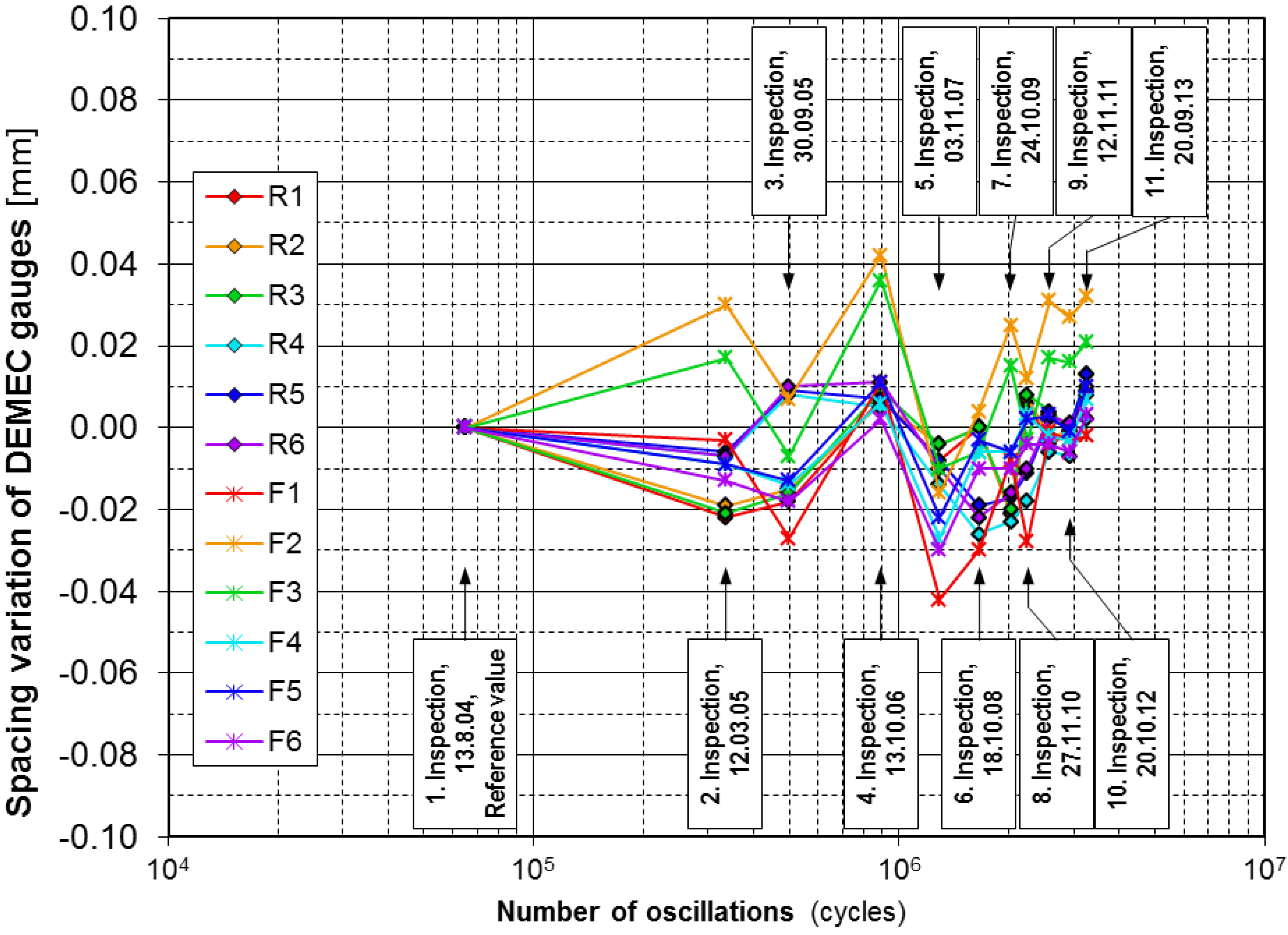
  • Several investigations reported on the presence of peel-off stresses normal to the adherend at the laminate ends (e.g., [26,30] or [35]). Some authors (e.g., [20]) proposed the need of clamping systems to reduce out-of-plane “peel-off” stresses when applying prestressed CFRP laminates to steel members. Peel-off stresses turned out as not critical after application of the CFRP laminate on the pendulum girder, since prestressing was only about 32% of the ultimate strength of the laminate. The pendulum girder did not show any indications of delamination at the laminate ends after nine years of service. It is considered important, that the ends of the applied CFRP laminates with a length of 6 m each are located at low fatigue stressed regions, near the ends of the steel box girder. Since the bending moment vanishes at the pendulum ends, the fatigue load transfer from the steel flanges into the CFRP laminates is also low. Hence the shear stress maxima in the bonding layer at the laminates’ ends have an almost static character, which is very beneficial with respect to the strength of the bonding layer. In an additional investigation by Ebnöter [28] it was observed that oscillating shear stress maxima lead to early debonding of applied prestressed CFRP laminates.
  • As already mentioned, welds are supposed to contain welding defects, which act as stress concentrators and fatigue crack starters respectively. Welds also contain residual stresses in the heat-affected zones that may reach the height of the yield stress of the steel material. These residual stresses were not taken into account, when determining the needed prestress force of the CFRP laminates. A higher prestress than 32% of the laminate's ultimate strength would have been needed to shift the maximum tension stress (superposition of tensile fatigue stresses and residual stresses) into the compression region.
Since residual tension stresses remain in the weld after strengthening, it appears evident that superposed alternate loading may initiate fatigue cracks even in case the nominal stresses are shifted completely to the compression region. However, fatigue cracks developing in the heat-affected zone of the weld will reduce these residual tensile stresses. As a result compressive nominal stresses will then promote crack closure effects and hence slow down crack propagation [35].

Abbreviations

CFRP
carbon fiber reinforced polymer
CTE
coefficient of thermal expansion
DEMEC
welding additive from Böhler Schweißtechnik Austria GmbH
DMO-IG
welding additive from Böhler Schweißtechnik Austria GmbH
Er
epoxy resin
FRP
fibre reinforced polymer
FKM
ForschungsKuratorium Maschinenbau
HV-screw
high strength screw used in pretensioned condition
Ma
methacrylate
MAG
metal activ gas welding
Phr
phenolic resin
Pu
polyurethane
TIG
tungsten inert gas welding

Symbols

Astrain at failure (metallic material)[-]
Ddiameter of welding rod[mm]
E11Young’s modulus in longitudinal direction[N/mm2]
Fptpretension force for CFRP laminates[kN]
ftest frequency[Hz]
R = σlowupstress ratio[-]
Rmultimate tensile strength[N/mm2]
Rpyield strength[N/mm2]
Rp0.2yield stress at 0.2% plastic strain[N/mm2]
rHrelative humidity[%]
sthickness of CFRP laminates[mm]
Ttemperature[°C]
Tgglass transition temperature[°C]
tthickness of adhesive film[mm]
tfthickness of glass fiber fabric[mm]
Vffiber volume[%]
wwidth of CFRP laminates[mm]
αCFRPcoefficient of thermal expansion for fibre reinforced composite[K−1]
αStcoefficient of thermal expansion for steel[K−1]
εfstrain at failure (composite material)[-]
ρspecific weight of glass fiber fabric[g/m2]
σlowminimum stress[MPa]
σresresidual compressive stress[MPa]
σupmaximum stress[MPa]
τmshear mean stress[MPa]

Acknowledgments

ETH-students R. Ginés, L. Schlagenhauf, J. Studer and F. Ebnöther are acknowledged for their experimental work. We are grateful to U. Meier for his advice with the strengthening of the Pendulum and to the Empa technicians W. Bollier, M. Heiniger and S. Moranduzzo for their practical support in laboratory and for specimen preparation. A. Winistörfer, CEO of Carbo-Link AG is acknowledged for his support with the design and strengthening work presented. We are grateful to companies Dow Automotive GmbH, Switzerland and Jenny Co. AG, Winterthur Switzerland for their support by sponsoring materials for the study.

Conflicts of Interest

The authors declare no conflict of interest.

References

  1. FKM-Guideline. Analytical Strength Assessment of Components in Mechanical Engineering; VDMA Verlag GmbH: Frankfurt, Germany, 2003. [Google Scholar]
  2. Weman, K. Welding Processes Handbook; CRC Press: Boca Raton, FL, USA, 2003. [Google Scholar]
  3. Loher, U.; Mueller, B.; Leutwiler, R.; Esslinger, V. CFRP-strengthened aluminum structures. In Proceedings of the 17th int SAMPE Europe Conference on Success of Materials by Combination, Basel, Switzerland, 28–30 May 1996; pp. 37–54.
  4. Duering, M. “Bemessung von mit CFK-Lamellen verstärkten Stahlbetonträgern”, Nachträgliche Verstärkung von Bauwerken mit CFK-Lamellen (Design of reinforced concrete beams strengthened with adhesively bonded CFRP laminates). In Proceedings of the EMPA/SIA Conference, Zurich, Switzerland, 21 September 1995.
  5. Meier, U.; Stoecklin, I.; Terrasi, G.P. Making better use of the strength of advanced materials in structural engineering. In Proceedings of the International Conference on FRP Composites in Civil Engineering, Hong Kong, China, 12–15 December 2001. FRP Composites in Civil Engineering.
  6. Sen, R.; Liby, L.; Mullins, G. Strengthening steel bridge sections using CFRP laminates. Composit. B Eng. 2001, 32, 309–322. [Google Scholar] [CrossRef]
  7. Miller, T.; Chajes, M.; Mertz, D.; Hastings, J. Strengthening of a steel bridge girder using CFRP plates. J. Bridge Eng. 2001, 6, 514–522. [Google Scholar] [CrossRef]
  8. Tavakkolizadeh, M.; Saadatmanesh, H. Fatigue strength of steel girders strengthened with carbon fiber reinforced polymer patch. J. Struct. Eng. 2003, 129, 186–196. [Google Scholar] [CrossRef]
  9. Jones, S.C.; Civjan, S.A. Application of fiber reinforced polymer overlays to extend steel fatigue life. J. Composit. Constr. 2003, 7, 331–338. [Google Scholar]
  10. Deng, J.; Lee, M.M.K. Fatigue performance of metallic beam strengthened with a bonded CFRP plate. Composit. Struct. 2007, 78, 222–231. [Google Scholar]
  11. Liu, H.; Al-Mahaidi, R.; Zhao, X.-L. Experimental study of fatigue crack growth behaviour in adhesively reinforced steel structures. Composit. Struct. 2009, 90, 12–20. [Google Scholar]
  12. Colombi, P.; Poggi, C. An experimental, analytical and numerical study of the static behavior of steel beams reinforced by pultruded CFRP strips. Composit. B Eng. 2006, 37, 64–73. [Google Scholar]
  13. Deng, J.; Lee, M.M.K. Behaviour under static loading of metallic beams reinforced with a bonded CFRP plate. Composit. Struct. 2007, 78, 232–242. [Google Scholar] [CrossRef]
  14. Dawood, M. Fiber-Reinforced Polymer (FRP) Composites for Strengthening Steel Structures; Woodhead Publishing Limited: Cambridge, UK, 2013; Volume 45, pp. 382–409. [Google Scholar]
  15. Schnerch, D.; Dawood, M.; Rizkalla, S.; Sumner, E. Proposed design guidelines for strengthening of steel bridges with FRP materials. Constr. Build. Mater. 2007, 21, 1001–1010. [Google Scholar] [CrossRef]
  16. Bassetti, A. Lamelles precontraintes en fibres carbone pour le renforcement de ponts rivetes endommaees par fatigue. Ph.D. Thesis, Swiss Federal Institute of Technology, EPFL, Lausanne, Switzerland, 2001. [Google Scholar]
  17. Bassetti, A.; Liechti, P.; Nussbaumer, A. Fatigue resistance and repairs of riveted bridge members. In European Structural Integrity Society; Marquis, G., Solin, J., Eds.; Elsevier: Lausanne, Switzerland, 1999; Volume 23, pp. 207–218. [Google Scholar]
  18. Täljsten, B.; Hansen, C.S.; Schmidt, J.W. Strengthening of old metallic structures in fatigue with prestressed and non-prestressed CFRP laminates. Constr. Build. Mater. 2009, 23, 1665–1677. [Google Scholar] [CrossRef]
  19. Ye, H.; Christian, K.; Thomas, U.; Qiang, S.; Robin, P. Fatigue performance of tension steel plates strengthened with prestressed CFRP laminates. J. Composit. Constr. 2010, 14, 609–615. [Google Scholar] [CrossRef]
  20. Ghafoori, E.; Motavalli, M.; Botsis, J.; Herwig, A.; Galli, M. Fatigue strengthening of damaged metallic beams using prestressed unbonded and bonded CFRP plates. Int. J. Fatigue 2012, 44, 303–315. [Google Scholar] [CrossRef]
  21. Walbridge, S.; Soudki, K.; Vatandoost, F. Fatigue retrofitting of welded steel cover plates using pre-stressed carbon fibre reinforced polymer strips. Struct. Eng. Int. 2011, 21, 279–284. [Google Scholar]
  22. EN 10025–1:2004. Hot rolled products of structural steels—Part 1: General technical delivery conditions, CEN, 2004. Available online: http://www.cen.eu (accessed on 15 November 2013).
  23. Ginés, R. Reinforcement of welded steel beams with prestessed CFRP laminates. B.Sc. Thesis, ETH, Zurich, Switzerland, 2006. [Google Scholar]
  24. ASTM D5868–01(2008). Standard Test Method for Lap Shear Adhesion for Fiber Reinforced Plastic (FRP) Bonding; ASTM: West Conshohocken, PA, USA, 1995. Available online: http://www.astm.org (accessed on 15 November 2013). [CrossRef]
  25. Schlagenhauf, L. Mechanische Charakterisierung von Strukturklebstoffen im Hinblick auf die Verstärkung von geschweissten Stahlträgern mit vorgespannten Kohlefaserlamelllen; Report No. 841312; Empa: Dübendorf, Switzerland, 8 June 2007. (in German) [Google Scholar]
  26. Stratford, T.; Cadei, J. Elastic analysis of adhesion stresses for the design of a strengthening plate bonded to a beam. Constr. Build. Mater. 2006, 20, 34–45. [Google Scholar] [CrossRef]
  27. Studer, J. Reinforcement of welded steel beams with adhesively bonded prestressed. B.Sc. Thesis, ETH, Zurich, Switzerland, 2007. [Google Scholar]
  28. Ebnöther, F. Reinforcement of welded steel beams with adhesively bonded prestressed CFRP laminates. Semester’s Thesis, ETH, Zurich, Switzerland, 2007. [Google Scholar]
  29. Koller, R. Fatigue Strength Assessment of a Welded Joint in the Artwork Pendulum; Test report 428643; Empa: Dübendorf, Switzerland, 2003. [Google Scholar]
  30. Hollaway, L.C.; Cadei, J. Progress in the technique of upgrading metallic structures with advanced polymer composites. Prog. Struct. Eng. Mater. 2002, 4, 131–148. [Google Scholar] [CrossRef]
  31. Koller, R.E.; Stoecklin, I.; Weisse, B.; Terrasi, G.P. Strengthening of fatigue critical welds of a steel box girder. Eng. Fail. Anal. 2012, 25, 329–345. [Google Scholar]
  32. Sika—Technical Data Sheet of Sika Carbodur® S512, version No. 8; Available online: http://chproducts.webdms.sika.com/fileshow.do?documentID=2263 (accessed on 15 November 2013).
  33. Toray—Technical Data Sheet of Toray M46J®. Available online: http://www.toraycfa.com/pdfs/M46JDataSheet.pdf (accessed on 21 November 2013).
  34. 3M—Technical Data Sheet of 3M Scotch Weld®9323 B/A. Available online: http://multimedia.3m.com/mws/mediawebserver?mwsId=SSSSSu7zK1fslxtU482e5Y_vev7qe17zHvTSevTSeSSSSSS--&fn=9323%2006–2002.pdf (accessed on 15 November 2013).
  35. Shaat, A.; Schnerch, D.; Fam, A.; Rizkalla, S. Retrofit of Steel Structures Using Fiber-Reinforced Polymers (FRP): State-of-the-Art; 04–4063 [CD-ROM]; Transportation Research Board (TRB) Annual Meeting: Washington, DC, USA, 2004. [Google Scholar]

