Article

Preparation of Polyoxymethylene/Exfoliated Molybdenum Disulfide Nanocomposite through Solid-State Shear Milling

1
The State Key Laboratory of Polymer Material Engineering, Polymer Research Institute, Sichuan University, Chengdu 610065, China
2
Baosheng Technology Innovation Corporation Limited, Yangzhou 225800, China
*
Author to whom correspondence should be addressed.
These authors contributed equally to this work.
Polymers 2024, 16(10), 1334; https://doi.org/10.3390/polym16101334
Submission received: 18 April 2024 / Revised: 4 May 2024 / Accepted: 6 May 2024 / Published: 9 May 2024

Abstract

:
In this paper, the solid-state shear milling (S3M) strategy featuring a very strong three-dimensional shear stress field was adopted to prepare the high-performance polyoxymethylene (POM)/molybdenum disulfide (MoS2) functional nanocomposite. The transmission electron microscope and Raman measurement results confirmed that the bulk MoS2 particle was successfully exfoliated into few-layer MoS2 nanoplatelets by the above simple S3M physical method. The polarized optical microscope (PLM) observation indicated the pan-milled nanoscale MoS2 particles presented a better dispersion performance in the POM matrix. The results of the tribological test indicated that the incorporation of MoS2 could substantially improve the wear resistance performance of POM. Moreover, the pan-milled exfoliated MoS2 nanosheets could further substantially decrease the friction coefficient of POM. Scanning electron microscope observations on the worn scar revealed the tribological mechanism of the POM/MoS2 nanocomposite prepared by solid-state shear milling. The tensile test results showed that the pan-milled POM/MoS2 nanocomposite has much higher elongation at break than the conventionally melt-compounded material. The solid-state shear milling strategy shows a promising prospect in the preparation of functional nanocomposite with excellent comprehensive performance at a large scale.

1. Introduction

The two-dimensional molybdenum disulfide (MoS2) has attracted extensive attention due to its excellent tribological performance and potential electrical and optical performance [1]. The weak layered structure of MoS2 gives it its perfect lubrication property [2], which makes the MoS2 particles widely used as additives in lubricating oils, greases, and solid materials [3]. However, the morphology of the MoS2 particle has a great influence on its ultimate tribological performance. It was found that the exfoliated nanoscale MoS2 (such as fullerene-like, tube-like, and platelet-like) showed better tribological performance than the conventional bulk MoS2 [4,5]. Hu et al. [6] investigated the tribological properties of liquid paraffin filled with nano-ball MoS2, nano-slice MoS2, and bulk MoS2, respectively. The results showed that nano-ball MoS2 showed the better tribological performance, and nano-slice MoS2 performed the best lubrication property at high rotation speed in the hydrodynamic lubrication region. In recent years, the ultrathin nanoscale MoS2 has been reported to fabricate some field effect transistors due to its thickness-dependent bandgap [7] and is also used as a catalyst for the hydrogen evolution reaction [8]. As a result, the nano-MoS2 substance has been considered a promising candidate for various future electric devices. As a consequence, the preparation of nano-MoS2 has attracted increasing attention [9].
The bulk MoS2 is mainly composed of Mo-S-Mo sandwich layers, where every molybdenum sheet is interacted between two sulfur sheets. It was found that there are three types of crystalline MoS2, including 1T, 2H, and 3R [10]. Among them, 2H-MoS2 appears to have the most outstanding tribological performance. The Mo and S atoms are connected by a chemical bond within the layer, and the neighboring layers are weakly stacked and connected through Van der Waals forces [11]. Thus, the bulk MoS2 can be exfoliated to a few-layer MoS2 under appropriate conditions. In recent years, micromechanical cleavage [12] and various chemical exfoliation methods [13] (such as hydrothermal synthesis, vapor phase decomposition, and laser thinning) have been reported to prepare ultrathin MoS2. The micromechanical cleavage showed high quality and simplicity, but was limited to difficult production at a large scale. On the other hand, the chemical exfoliation method presented a relatively complicated procedure. Therefore, a simple and effective method for large-scale fabrication of nano-MoS2 with low cost has not been reported thus far. It is also reported that the previously prepared nano-MoS2 particles had a high surface energy and tend to be agglomerated when melt-compounded with the polymer matrix directly [14]. Xu [2] et al. confirmed that the MoS2 nanoplatelet particles presented bad dispersibility in rapeseed oil, which would lead to an increase in wear. Clearly, it is really extremely difficult to prepare the exfoliated nano-MoS2 with a good dispersion in the polymer matrix by only using an ordinary physical approach. This is because the interlayer spacing of the MoS2 is extremely small (as low as 0.65 nm).
Solid-state shear milling (S3M), a technology based on our self-designed pan-milling equipment [15], has been well developed in our laboratory for many years. This technology has been successfully adopted to achieve the preparation of highly filled polymer composites [16], ultrafine grinding of polymer/inorganic micro-nano composites [17,18], and recycling of wasted polymers [19,20]. The oppositely inlaid twin mill-pans of the above-mentioned pan-milling equipment can act as three-dimensional scissors during pan-milling, which could exert very strong compression, shear, and hoop stretching stresses for pulverization, dispersion, mixing, and mechanochemical activation on the milled materials. In our team’s previous work, the S3M strategy was able to efficiently cut the multi-wall carbon nanotubes and induce strong interfacial interactions with the polyamide 6 matrix [21]. This technology proved to effectively solve the compatibility problem and control the phase morphology of the nano-fillers in the polymer matrix. On this basis, the S3M technology is expected to be a potential and new simple physical approach to exfoliate and disperse MoS2 in a polymer matrix in a solid state. The polymer polyoxymethylene (POM) is an engineering plastic with excellent processability, mechanical, and tribological performance. It had been widely used as a self-lubrication material in many fields, such as engineering, automotive, and aerospace [22]. However, the neat POM still cannot satisfy the requirements as a sliding part in some extreme conditions, especially for those applied in ultra-small mechanical sliding devices with high temperatures and high loads [23]. Therefore, compounding with nano-MoS2 particles seems like a feasible method to further improve tribological performance and expand the application fields of POM.
Accordingly, in this work, the S3M technology was used to mechanochemically treat the mixture of pristine bulk MoS2 and POM at a solid state and on a large scale, aiming to effectively exfoliate and disperse the MoS2 particles in the POM matrix without aggregation, taking advantage of the very strong pulverization, dispersion, mixing, and mechanochemical activation functions. For comparison, the conventional POM/MoS2 composite was also prepared by twin-screw melt-compounding extrusion. The morphology and dispersion of MoS2 in the POM matrix, as well as the mechanical and tribological properties of the prepared POM/MoS2 nanocomposite, were fully investigated. This S3M strategy can successfully and efficiently realize the nano-exfoliation of MoS2 particles at a large scale, and the obtained POM/MoS2 nanocomposite exhibits excellent tribological and mechanical performance, thus exhibiting promising application prospects.

2. Experimental

2.1. Material

POM (M90), with an 80,000–100,000 average molecular weight, melt flow index of 9 g/10 min at 190 °C, and density of 1.4 g/cm3, was purchased from Yuntianhua Group, Chongqing, China. MoS2 with a particle size less than 47 μm was purchased from Tianjin Chemical Industry, Tianjin, China.

2.2. Sample Preparation

2.2.1. Preparation of POM/MoS2 Composite

The MoS2 was first mixed with POM pellets in a high-speed mixer, and the loading of MoS2 was fixed at 15 wt%. Then, the pan-milling equipment was applied to pulverize and mill the mixture with a rotation speed of 20 rpm. The discharged co-powders were collected for the next milling cycle. The heat generated during pan-milling was removed by the circulating water. A small quantity of the milled POM/MoS2 co-powders was collected for characterization every 10 milling cycles. After 40 milling cycles were finished, the obtained POM/MoS2 co-powders were firstly dried in an oven at 60 °C for 12 h and then used as the master batch and diluted to the MoS2 content at 2 wt% by adding the dried neat POM and 0.5 wt% of the antioxide agent IRGANOX 245 to avoid mechanochemical degradation. Subsequently, the well-mixed mixtures with 2 wt% MoS2 were extruded in a twin-screw extruder (Φ = 25 mm, L/D = 33, Chenguang Research Institute of Chemical Industry, China) with a screw rotation speed of 120 rpm at 180 °C, and the cooled extrudates were cut into pellets and dried. For purposes of comparison, the pristine MoS2 particles were also well mixed with the dried neat POM and 0.5 wt% of the antioxide agent IRGANOX 245 in a high-speed mixer and then simply melt-compounded in the above-mentioned twin-screw extruder under the same conditions.

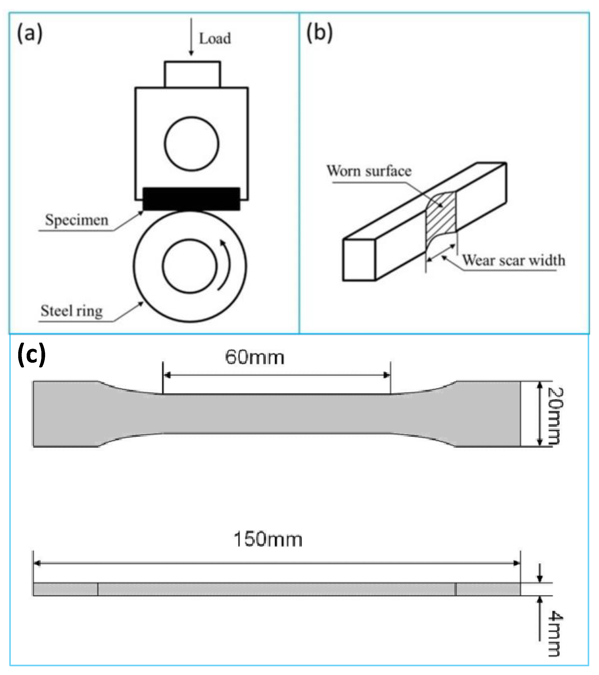
2.2.2. Preparation of POM/MoS2 Composite Samples for Tensile and Tribological Tests

The dumbbell-shaped specimens with a dimension of 150 mm × 20 mm × 4 mm (L × W × T) for the tensile test were prepared by using a MA500II injection molding machine (Ningbo Haitian Co., Ltd., Ningbo, China) with an injection speed of 50 mm/s at 180 °C. The samples for the tribological test were first compression-molded into sheets at 180 °C with 20 MPa and then cut into samples with a dimension of 30 mm × 7 mm × 6 mm (L × W × T).

2.3. Characterization

The scanning electron microscope (SEM) morphology of the S3M (milled) and conventionally melt-compounded (unmilled) POM/MoS2 composites was observed on an Inspect F Scanning electron microscope (FEI Company, Hillsboro, OR, USA) with an accelerating voltage of 20 kV. Before observation, the worn scar of samples after the friction and wear tests and also the fractured surface of samples after tensile tests were coated with a thin gold layer to prevent charging on the surface. The polarized light microscope (PLM) morphology was observed by a DM2500p microscope (Leica Camera AG, Wetzlar, Germany). Before observation, the samples were meticulously prepared by cryogenically ultramicrocutting them into 20 μm slices from the injection-molded sheet using an ultramicrotome machine. The milled and unmilled POM/MoS2 composites were melted at 180 °C and controlled by the THMSG600 heating and cooling stage (Linkam Scientific Instruments, Salfords, UK). The X-ray diffraction (XRD) analysis of the milled and unmilled POM/MoS2 composites was performed using a DX-1000 diffractometer (Dandong Fangyuan Instrument Co., Ltd., Dandong, China). The CuKα generator system was operated at 40 kV and 25 mA, and the scanning 2θ ranged from 5° to 35°. The transmission electron microscope (TEM) was performed on a Tecnai G2 F20 electron microscope (FEI Company, Hillsboro, OR, USA) with an accelerating voltage of 200 kV. The injection-molded samples of milled and unmilled POM/MoS2 composites were cryogenically ultramicrocut into 80–100 nm thin slices at −100 °C using a LEICA EM FC6 frozen ultramicrotome. The POM/MoS2 thin films were then placed on the copper grids for observation. The Raman measurements were conducted on the pristine MoS2 and POM/MoS2 co-powders with 40 milling cycles by using a LabRAM HR Laser Raman spectrometer (HORIBA Company, Palaiseau, France) at room temperature with an excitation wavelength of 532 nm. The friction and wear tests were conducted using a MC-200 friction and abrasion testing machine (Beijing Guance Testing Instrument Co., LTD., Beijing, China) with a block-on-ring arrangement at room temperature with a rotation of 120 rpm and a load of 200 N for 60 min. The schematic diagram of the friction and wear testing experiment is shown in Figure 1a. The wear loss was determined by the wear scar width (Figure 1b). The friction torques (T) were recorded every second, and the friction coefficient (μ) was defined by an equation of μ = T/MR, where μ was the friction coefficient, T was the average friction torque (Nm), M was the load (N), and R was the radius of the steel ring (m), respectively.
The tensile property measurement of the milled and unmilled POM/MoS2 composites was performed on injection-molded dumbbell-shaped specimens using a 5567 type of Instron Universal Testing machine (Instron Company, Buckinghamshire, UK) with a cross-head rate of 10 mm/min at room temperature.

3. Results and Discussion

3.1. Preparation and Structure Characterization of POM/MoS2 Nanocomposite

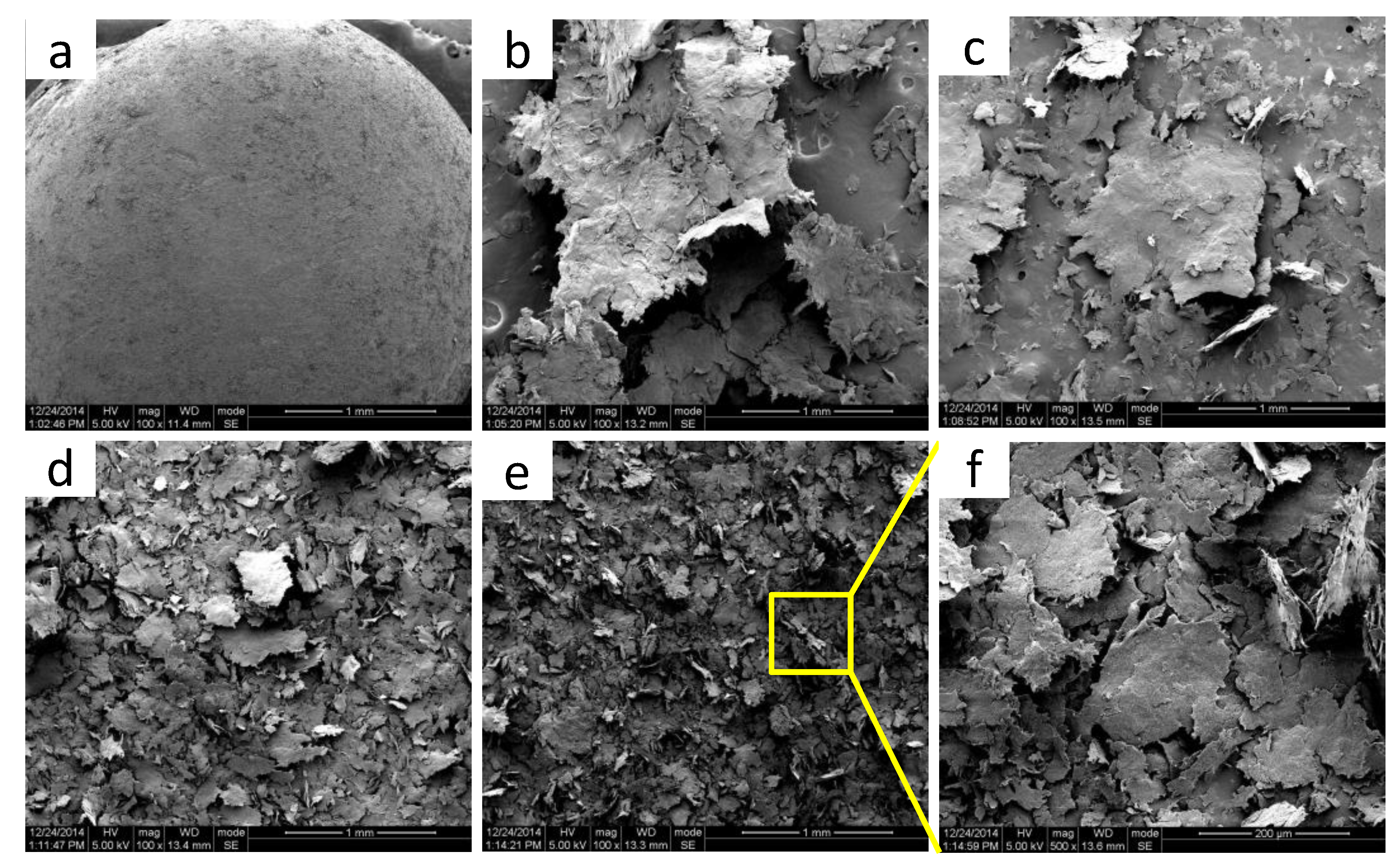
3.1.1. Morphology Evolution of S3M POM/MoS2 Co-Powders

The morphology development of POM/MoS2 co-powders prepared at different milling cycles was observed by SEM, and the results are shown in Figure 2. As can be seen, the MoS2 particles are adhered to the ball-like POM particles through simple physical mixing (in a high-speed mixer) before pan-milling treatment. The milled POM/MoS2 co-powder particles with low milling cycles (10) show a sheet structure under the effect of the very strong compression, shear, and hoop stretching stress fields generated by pan-milling. It is noted that the sheet-like POM powder particles possess a relatively higher specific surface area and benefit from sufficient contact with MoS2 particles. Moreover, the MoS2 particles have the opportunity to be imbedded into the POM matrix under strong compression stress. As a consequence, it is promising to achieve good dispersion of MoS2 filler particles in the POM matrix by using this strategy. With increasing milling cycles, the POM/MoS2 co-powders keep the same sheet structure, but the size of the sheet particles becomes much smaller and thinner, indicating the high efficiency of the S3M technology. The final size of the POM/MoS2 co-powder particles with 40 milling cycles could further decrease to 200 μm with the effect of the continuous pulverization and mixing provided by S3M.

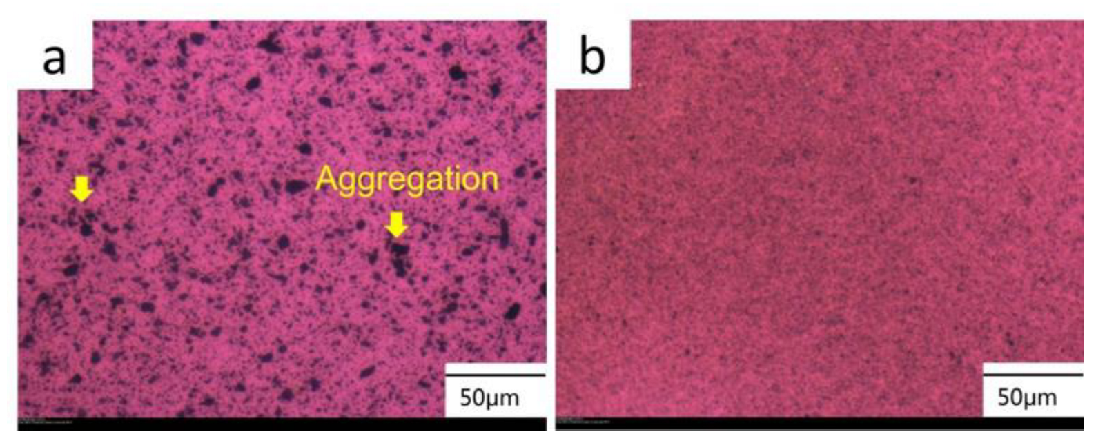
3.1.2. The Dispersion of MoS2 Particles in POM Matrix

The dispersion behavior of the incorporated MoS2 particles in the conventionally unmilled and milled POM/MoS2 composite was observed using PLM. The results are shown in Figure 3. Obviously, for the conventionally melt-compounded sample (Figure 3a), the opaque black areas represent the MoS2 particles, which basically appear to have a size in the range of microns. There is a heavy agglomeration of MoS2 particles occurring in the POM matrix, demonstrating the poor dispersion effect of twin-screw extrusion processing. This could be due to the high surface energy and interaction potential of the MoS2 particles. Comparatively, for the pan-milled sample (Figure 3b), the dispersion of MoS2 particles in the POM matrix is substantially improved. The individual MoS2 particle cannot be clearly identified due to the great reduction in filler particle size after milling. The above results again verify the high efficiency of S3M technology. This is because the MoS2 particles are efficiently pulverized and imbedded into the POM matrix under the strong compression, shear, and hoop stretching stresses induced by pan-milling. Thus, the S3M strategy could be applied to effectively solve the aggregation problem of the pristine bulk MoS2 particles in the POM matrix.

3.1.3. Crystal Structure of S3M POM/MoS2 Co-Powders

Figure 4 shows the XRD patterns of pristine MoS2, neat POM, and POM/MoS2 co-powders with different milling cycles. As can be seen, the diffraction patterns of MoS2 mainly appear in three peaks at 14.6°, 32.8°, and 33.7° in the detected 2θ range, which correspond to the (002), (100), and (101) crystal planes of 2H-MoS2 [24], respectively. The diffraction peaks located at 22.8° and 34.6° are attributed to the (100) and (105) crystal plane of POM, respectively [25]. As can be seen, the diffraction peak intensities of MoS2 and POM decrease sharply after 10 milling cycles, indicating the breakage of original crystal crystallites and distortion of the three-dimensional crystalline order of MoS2 after the S3M process [26]. In addition, the diffraction peak intensities of MoS2 (002) and POM (100) show a decreasing tendency with further increase of milling cycles. According to the Scherrer equation:
D = k λ β cos θ
where D is the crystalline size (nm), λ is the X-ray wavelength in nanometer (nm), β is the full width at half maximum (FWHM), k is the scherrer constant, and θ is the diffraction angle.
Accordingly, the crystalline size can be calculated by using the full width at half maximum (FWHM) of the diffraction peak and diffraction angle. Apparently, the crystalline size of MoS2 decreases with increasing milling cycles, indicating the constant milling treatment could destroy the inner-ordered stacking of MoS2. Hence, the layered structures of MoS2 are expected to be exfoliated using the S3M strategy, which will be further confirmed by the following TEM characterization. Moreover, the diffraction profiles of MoS2 particles with different milling cycles show similar featured peaks, implying that the 2H crystal type of MoS2 does not change after pan-milling.

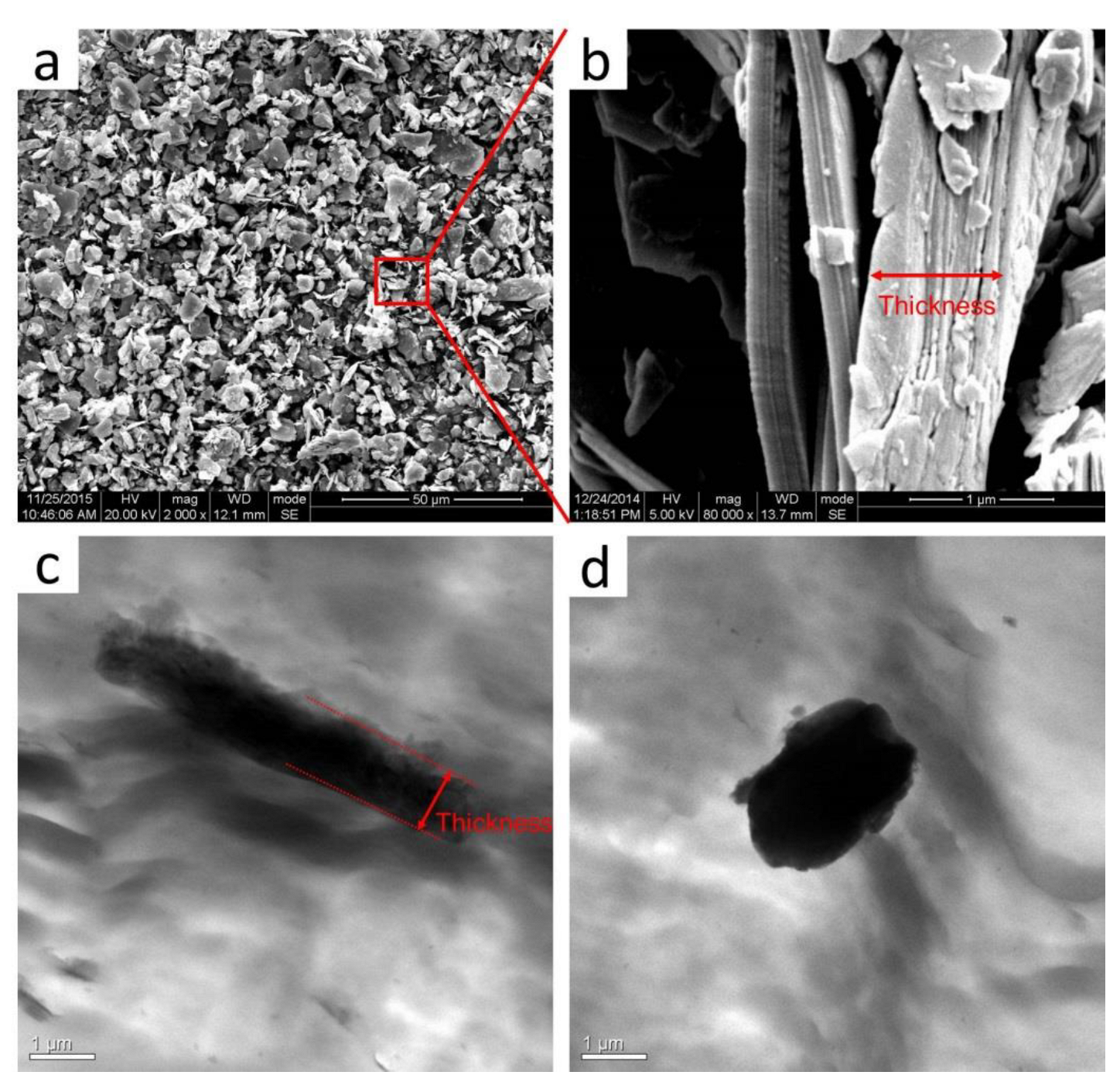
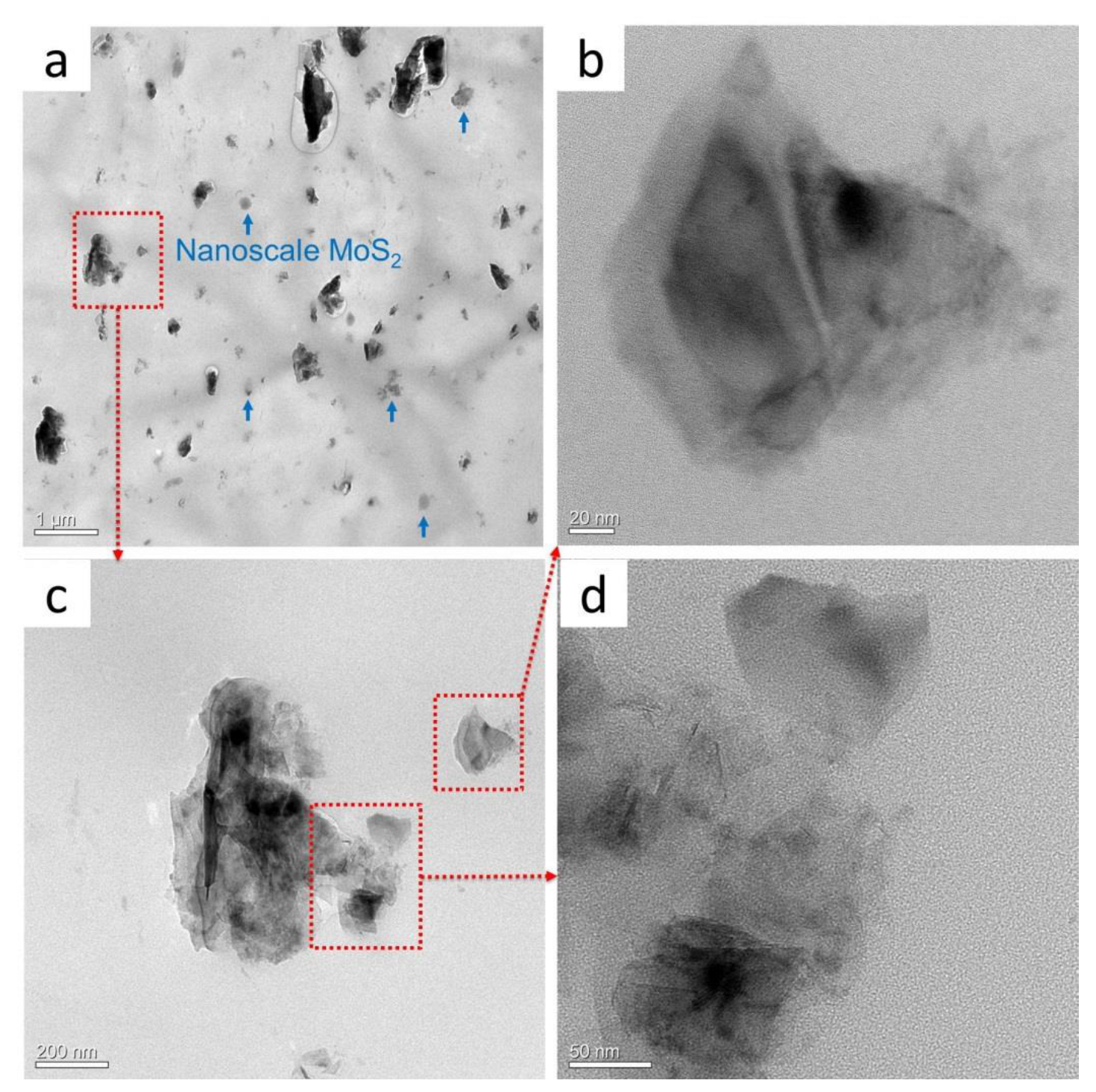
3.1.4. The Microscopic Morphology of MoS2 in the POM Matrix

The dispersion morphology and crystallization structure of pan-milled POM/MoS2 nanocomposite were well explored, but the ultimate microscopic morphology of MoS2 particles after S3M processing is still not clear. Figure 5a,b show the SEM images of the pristine bulk MoS2 particles. As can be seen, most of the pristine MoS2 particles show a size distribution in the micron range, and some particles have a length dimension up to 20 μm. Meanwhile, the stacking layered structure can be clearly observed (Figure 5b, enlarged image), and the thickness of some large-size particles could achieve 1 μm. The morphology of MoS2 in the conventionally unmilled composite is observed by TEM (Figure 5c,d), and the dark area indicates the MoS2 particles. As can be seen, the thickness stays at the micron scale. MoS2 exists as pristine bulk agglomerates in the POM matrix, and the poor shear stress field of the twin-screw extruder could not induce the structural change of the pristine MoS2 particles.
As a comparison, the morphology of MoS2 particles in the milled POM/MoS2 nanocomposite was observed using TEM, and the results are shown in Figure 6. As can be seen from Figure 6a, a small number of larger-size MoS2 particles can still be observed, while the size is much smaller than that of the original pristine particles. Meanwhile, a large quantity of nanoscale particles with a dimension of about hundreds of nanometers can be clearly identified. Figure 6b–d show the magnified morphologies of these nanoscale particles. As can be seen, there are few-layer nanosheets of MoS2 particles formed in the polymer matrix, clearly indicating the successful exfoliation of bulk MoS2 particles taking advantage of the very strong three-dimensional shear stress field of pan-milling. This is a breakthrough in the preparation of the exfoliated MoS2 in its solid state by only adopting a simple physical strategy. Some details could be further known from Figure 6b–d. For Figure 6b, the center region of particles appears translucent, implying only a few layers overlapping one another. The particle edge is transparent, indicating a much thinner structure in this area [8]. Figure 6c shows the TEM image of a larger particle (in small magnification). It can be seen that the center area appears opaque, while the edge region is translucent, indicating that these particles are partially exfoliated. Figure 6d further shows the magnified edge region of the larger particle, and it appears nearly transparent, apparently with a high exfoliation occurring here. It is noted that this region is weakly combined with the larger particle and seems to be separated from the larger one. Therefore, it can be speculated that these exfoliated nano-MoS2 were crushed and fractured on the surface of larger particles and finally delaminated from them via a S3M process.

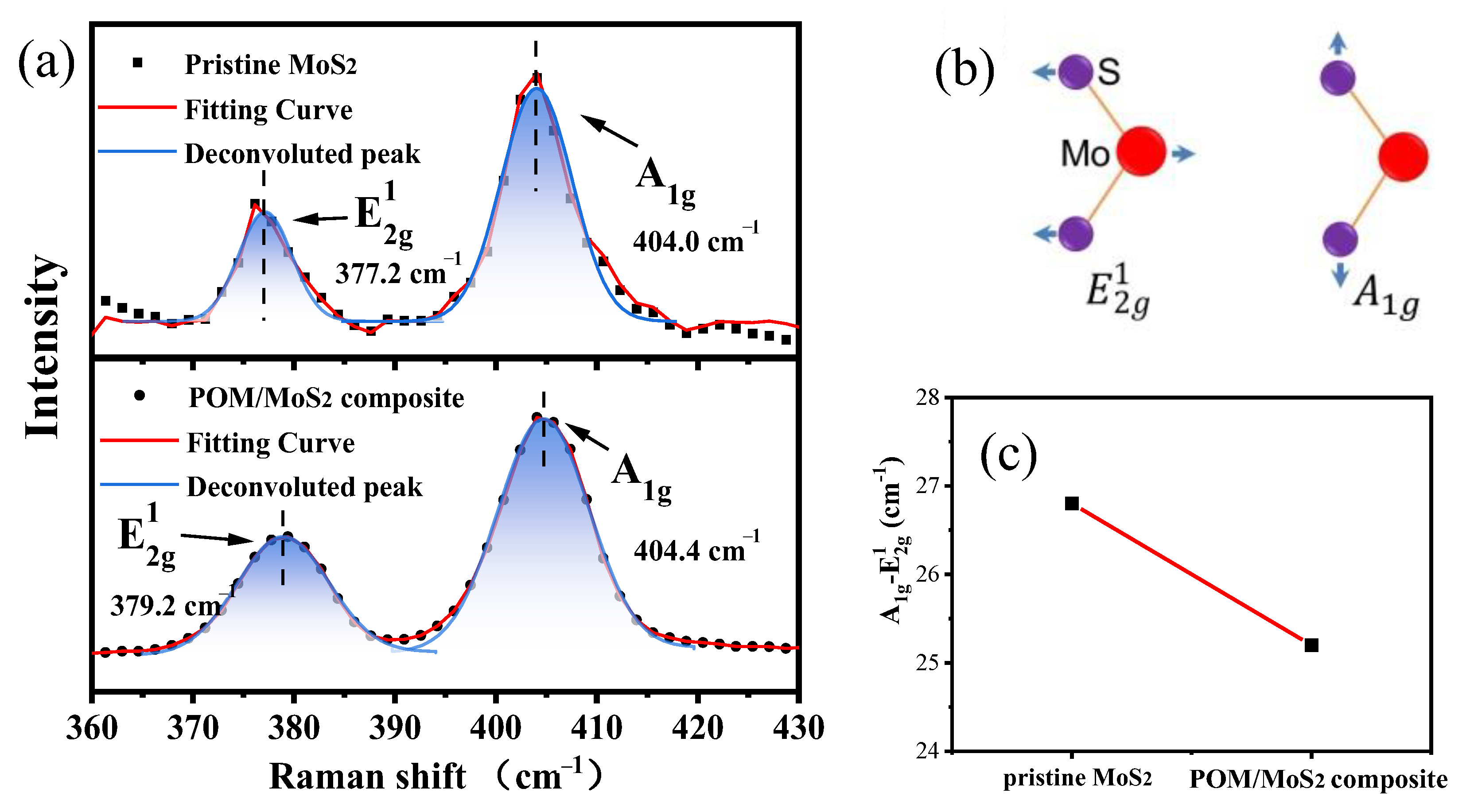
3.1.5. Raman Spectra of Pristine MoS2 and S3M MoS2/POM Nanocomposite

In this section, Raman spectroscopy, which is widely applied to investigate the two-dimensional material for thickness identification, was used to further evaluate the exfoliation of MoS2 particles after pan-milling. Figure 7 shows the Raman spectra of pristine MoS2 and milled POM/MoS2 nanocomposite with 40 milling cycles. It can be seen that there are two main peaks clearly presented, which are corresponding to E 2 g 1 (377.2 cm−1, in-plane vibration of two S atoms with respect to Mo atom) and A1g (404.0 cm−1, out-of-plane vibration of S atoms) [27] (as shown in Figure 7b). Here, it is noted that the frequency of E 2 g 1 increases after 40 milling cycles. It has been proven that the E 2 g 1 frequency shifts in a high wavenumber direction due to the exfoliation of layered structure, which can be attributed to the influence of neighboring layers on the effective restoring force on atoms and the increase in dielectric screening of long-range Coulomb interactions [28]. As a consequence, the frequency difference between the A1g and E 2 g 1 decreases from 26.8 cm−1 to 25.2 cm−1 after S3M treatment, further verifying that the bulk MoS2 particles are successfully exfoliated into few-layer nanosheets of MoS2 [29].

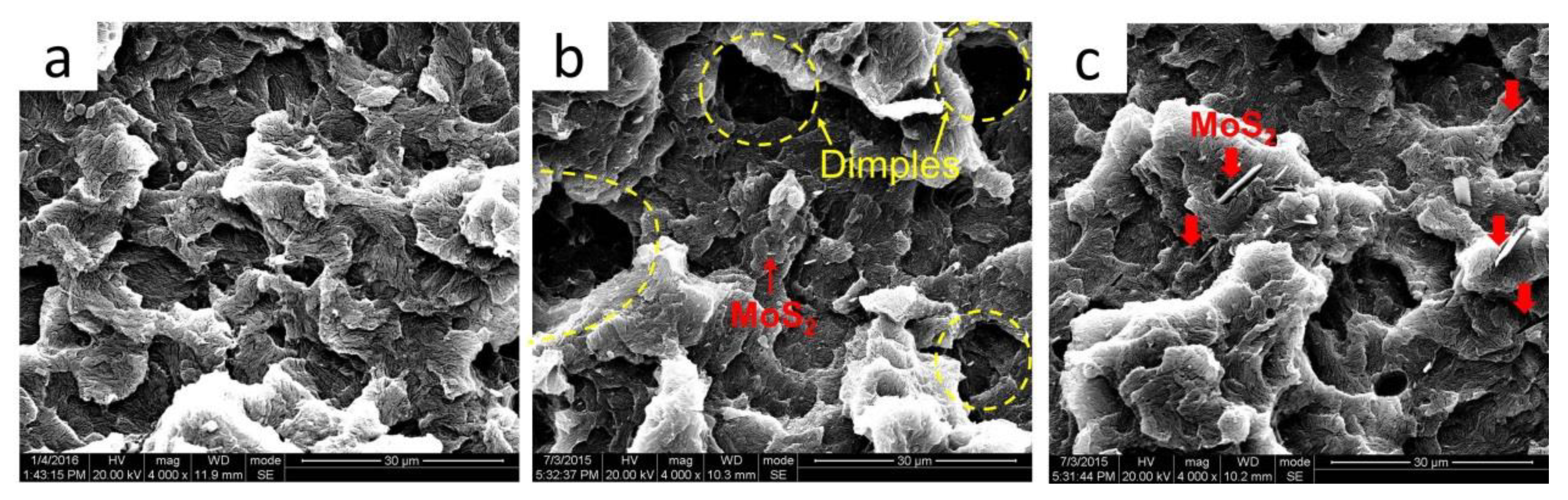
3.2. Tribological Performance of POM/MoS2 Nanocomposite

The friction coefficient and wear loss of the milled nanocomposite, conventionally unmilled composite, and neat POM are shown in Figure 8. As can be seen, the pan-milled POM/MoS2 nanocomposite shows the lowest friction coefficient, while the conventionally melt-compounded POM/MoS2 composite presents an increase in friction coefficient when compared with neat POM, indicating that the exfoliated nano-MoS2 particles could really remarkably decrease the friction coefficient, while the pristine bulk MoS2 particles have the most negative influence on the friction coefficient. On the other hand, the S3M-processed and conventionally prepared composites present a lower wear loss than the neat POM, indicating the incorporation of MoS2 could effectively improve the abrasion property of POM.
In order to deeply understand the effect of incorporated MoS2 on the friction and wear behaviors of POM, the morphology of the worn surface of neat POM, milled, and conventionally unmilled composites was investigated, and the results are shown in Figure 9. As can be seen, the worn surface of the neat POM appears to have obvious scratch grooves and some small debris. Many investigations [30,31] indicated that the wear mechanism of neat POM is governed by adhesion wear. Hence, the worn surface is plowed by its hard counterpart (spinning steel ring). Meanwhile, the plastic deformation may occur due to the lower hardness of the POM matrix. Additionally, the transfer film cannot be formed in neat POM [30], as a consequence of the higher wear loss of neat POM. The worn surface of S3M-processed POM/MoS2 nanocomposite appears the smoothest, and there are only some shallow scratch grooves, which can be observed. The improved wear resistance of the milled POM/MoS2 nanocomposite can be attributed to the formation of a 2H-MoS2 transfer film on the counterpart surface [32]. The worn surface of conventionally melt-compounded POM/MoS2 composite appears roughest, and the obvious plow-like gaps can be identified clearly. This large-size debris in the scratch grooves could probably be caused by the big MoS2 agglomerates plowed out in the POM matrix during the test. Additionally, there are also large quantities of MoS2 particles observed on the worn surface. This confirms that the bulk 2H-MoS2 particles easily form the transfer film, and sliding then occurs on the MoS2 lubrication film, which can possibly explain the reason why the conventionally prepared POM/MoS2 composite could present a relatively lower wear loss.
Based on the above results, a friction and wear mechanism could be proposed. Figure 10 demonstrates the sliding process of the POM/MoS2 composite. In the conventionally prepared POM/MoS2 composite, there are large-size MoS2 particles (in the range of 1~30 μm) dispersed in POM, which play a primary role in separating the frictional pairs. Besides, the two-dimensional MoS2 generally possesses an extremely high strength perpendicular to the thickness direction [33], which could probably plow out the POM in the sliding process, leading to the obvious scratch grooves. However, the pan-milled POM/MoS2 nanocomposite appears to have the smoothest worn surface, indicating that the exfoliated nano-MoS2 particles could improve the anti-wear performance. The size of the exfoliated nano-MoS2 particle (in the range of nanometers) is smaller than the surface roughness (0.8 μm) of the steel ring used. Thus, the ultrathin MoS2 particles can easily enter the contact area of the steel ring and then prevent the POM matrix from being worn [34]. The overall friction coefficient μ in a tribological test can be divided into two parts, i.e., the adhesion term μa and the plowing term μp. Certainly, the friction coefficient μ can be defined by the equation μ = μa + μp [35]. Obviously, the lowest friction coefficient of the milled POM/MoS2 nanocomposite can be attributed to the lower ratio of plowing due to the smoothest worn surface. Comparatively, the obvious scratches of the conventionally prepared POM/MoS2 composite mean a higher ratio of plowing term, certainly resulting in a higher coefficient. As a result, the S3M-processed POM/MoS2 nanocomposite can have much better tribological performance.

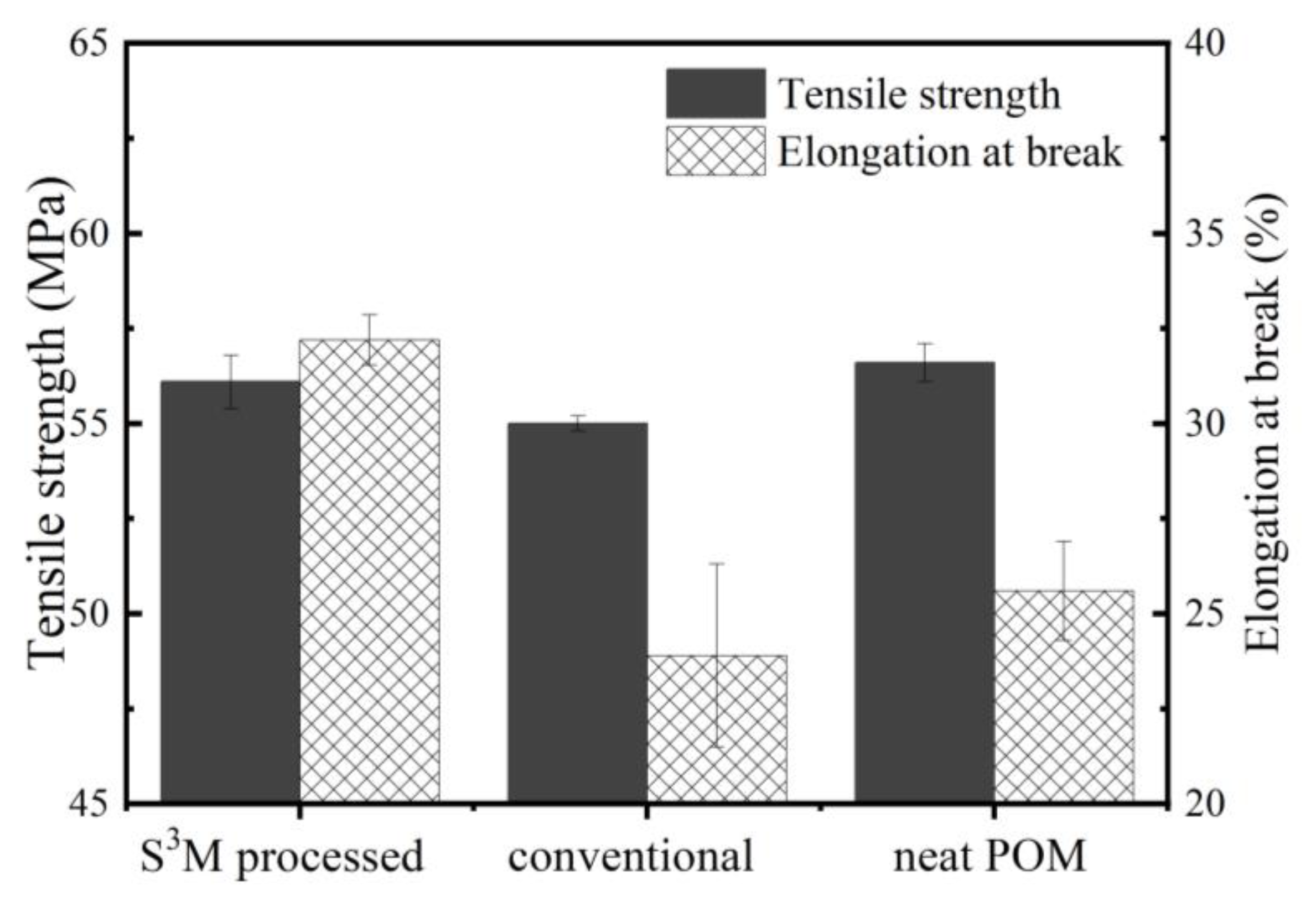
3.3. Mechanical Performance of POM/MoS2 Nanocomposite

Figure 11 shows the mechanical performance of different samples. It can be seen that the tensile strength of the milled and unmilled POM/MoS2 composites is slightly lower than that of neat POM, possibly due to the degradation effect of MoS2. Obviously, the slight decrease would have little influence on the ultimate application of S3M-processed POM/MoS2 nanocomposite. Compared with the conventionally prepared POM/MoS2 composite and neat POM, the elongation at break of the S3M-processed POM/MoS2 nanocomposite increases remarkably. Very clearly, the excellent comprehensive performance of POM/MoS2 nanocomposite can be obtained using S3M technology.
In order to deeply understand the influence of the S3M process on the mechanical performance, the fractured surface of the sample after the tensile test was observed by SEM, and the results are shown in Figure 12. As can be seen, the fractured surface of S3M-processed POM/MoS2 nanocomposite is uneven, and there are some deep dimples there, which can absorb a substantial amount of energy during a tensile test. On the other hand, the dot-like MoS2 particles appear nearly invisible, possibly due to the nanoscale dispersion, and the extremely small, rigid MoS2 particles would lead to local crazes, which benefit yielding and plastic deformation under stress fields [36]. As a result, the S3M-processed nanocomposite can have higher elongation at break. The fractured surface of the unmilled POM/MoS2 composite also appears uneven, but the dimples have almost disappeared. There are some large MoS2 particles that can be identified, and there are also some holes caused by the pulling out of MoS2 particles upon fracture, indicating the bad compatibility between MoS2 and POM. In addition, these large MoS2 particles would lead to stress concentration. As a result, the conventionally prepared POM/MoS2 composite shows poor mechanical properties.

4. Conclusions

The solid-state shear milling (S3M) technology was adopted to prepare the POM/MoS2 nanocomposite. As a comparison, the conventional melt-compounding method was also performed to prepare the POM/MoS2 composite in a twin-screw extruder. The dispersion and exfoliation of MoS2 particles, tribological properties, and mechanical performance of the above-prepared POM/MoS2 composites were comparatively investigated. The results show that the S3M strategy has a much better dispersion and exfoliation effect on the MoS2 particles than the traditional melt-compounding method. Under the effect of the very strong three-dimensional shear stress field induced by S3M, the pristine bulk MoS2 particles were pulverized into nanoscale particles and particularly efficiently exfoliated to few-layer 2H-MoS2 nanosheets at a large scale, which is verified by TEM, Raman, and XRD measurements. The dispersion of MoS2 particles in the POM matrix has accordingly improved substantially. On the contrary, the simple melt-compounding extrusion does not have any influence on the dispersion and exfoliation of MoS2 particles, and there is heavy agglomeration of filler particles in the matrix due to the poor shear stress field of the twin-screw extruder. Correspondingly, the S3M-processed POM/MoS2 nanocomposite shows substantially better tribological and mechanical properties than the traditionally melt-compounded material. Although incorporation of MoS2 could improve the anti-wear performance of POM, the S3M-processed nanocomposite shows a significantly lower friction coefficient due to nanoscale MoS2 decreasing the plowing effect. Meanwhile, the successfully exfoliated MoS2 nanosheets of S3M could substantially enhance the elongation at break of the POM/MoS2 composite. Therefore, the S3M strategy could show a very promising prospect in the preparation of POM/MoS2 functional nanocomposites with excellent comprehensive performance.

Author Contributions

Conceptualization, S.F., X.Z. (Xinwen Zhou) and Y.C.; Methodology, S.F., X.Z. (Xinwen Zhou) and J.T.; Validation, X.Z. (Xinwen Zhou) and X.Z. (Xu Zhu); Formal analysis, S.Y. and M.C.; Investigation, S.F., X.Z. (Xinwen Zhou), S.Y., J.T. and M.C.; Resources, H.Z., S.W. and H.G.; Data curation, S.F. and X.Z. (Xinwen Zhou); Writing—original draft, S.F., X.Z. (Xinwen Zhou) and S.Y.; Writing—review and editing, Y.C.; Visualization, S.F. and S.Y.; Supervision, Y.C.; Project administration, Y.C. and H.Z.; Funding acquisition, Y.C. All authors have read and agreed to the published version of the manuscript.

Funding

International Science & Technology Innovation Cooperation Project of Sichuan Province (24GJHZ0037), International Science & Technology Cooperation Project of Chengdu (2021-GH03-00009-HZ), Program for Featured Directions of Engineering Multi-disciplines of Sichuan University (2020SCUNG203) and Program of Innovative Research Team for Young Scientists of Sichuan Province (22CXTD0019).

Institutional Review Board Statement

Not applicable.

Data Availability Statement

Data are contained within the article.

Conflicts of Interest

Author Huarong Zhang, Xu Zhu, Shulong Wu and Haidong Gu were employed by the company Baosheng Technology Innovation Corporation Limited. The remaining authors declare that the research was conducted in the absence of any commercial or financial relationships that could be construed as a potential conflict of interest.

References

  1. Ao, D.; Fan, X.; Zeng, Z.; Zhu, M.; Ye, X.; Shang, L. Tribological properties of graphene quantum dot hybrid polyethylene glycol lubricated molybdenum disulfide films. Tribol. Int. 2024, 193, 109437. [Google Scholar] [CrossRef]
  2. Xu, Z.Y.; Hu, K.H.; Han, C.L.; Hu, X.G.; Xu, Y.F. Morphological Influence of Molybdenum Disulfide on the Tribological Properties of Rapeseed Oil. Tribol. Lett. 2013, 49, 513–524. [Google Scholar] [CrossRef]
  3. Jiang, Z.; Sun, Y.; Liu, B.; Yu, L.; Tong, Y.; Yan, M.; Yang, Z.; Hao, Y.; Shangguan, L.; Zhang, S. Research progresses of nanomaterials as lubricant additives. Friction 2024, 1–45. [Google Scholar] [CrossRef]
  4. Rapoport, L.; Moshkovich, A.; Perfilyev, V.; Laikhtman, A.; Lapsker, I.; Yadgarov, L.; Rosentsveig, R.; Tenne, R. High Lubricity of Re-Doped Fullerene-Like MoS2 Nanoparticles. Tribol. Lett. 2011, 45, 257–264. [Google Scholar] [CrossRef]
  5. Chhowalla, M.; Amaratunga, G.A.J. Thin films of fullerene-like MoS2 nanoparticles with ultra-low friction and wear. Lett. Nat. 2000, 407, 164–167. [Google Scholar] [CrossRef]
  6. Hu, K.H.; Hu, X.G.; Xu, Y.F.; Huang, F.; Liu, J.S. The Effect of Morphology on the Tribological Properties of MoS2 in Liquid Paraffin. Tribol. Lett. 2010, 40, 155–165. [Google Scholar] [CrossRef]
  7. Bao, W.; Cai, X.; Kim, D.; Sridhara, K.; Fuhrer, M.S. High mobility ambipolar MoS2 field-effect transistors: Substrate and dielectric effects. Appl. Phys. Lett. 2013, 102, 042104. [Google Scholar] [CrossRef]
  8. Voiry, D.; Salehi, M.; Silva, R.; Fujita, T.; Chen, M.; Asefa, T.; Shenoy, V.B.; Eda, G.; Chhowalla, M. Conducting MoS2 nanosheets as catalysts for hydrogen evolution reaction. Nano Lett. 2013, 13, 6222–6227. [Google Scholar] [CrossRef]
  9. Cui, Y.L.S.; Zhang, Y.Z.; Cao, Z.J.; Gu, J.N.; Du, Z.G.; Li, B.; Yang, S.B. A perspective on highentropy twodimensional materials. SusMat 2022, 2, 65–75. [Google Scholar] [CrossRef]
  10. Enyashin, A.; Gemming, S.; Seifert, G. Nanosized allotropes of molybdenum disulfide. Eur. Phys. J. Spec. Top. 2007, 149, 103–125. [Google Scholar] [CrossRef]
  11. Visic, B.; Dominko, R.; Gunde, M.K.; Hauptman, N.; Skapin, S.D.; Remskar, M. Optical properties of exfoliated MoS2 coaxial nanotubes—Analogues of graphene. Nanoscale Res. Lett. 2011, 6, 593. [Google Scholar] [CrossRef]
  12. Yu, M.; Jiang, C.; Yan, B.; Lin, L.; Wang, S.; Gong, T.; Guo, J.; Huang, W.; Zhang, X. A highly sensitive MoS2/MoTe2 heterostructure enhanced by localized surface plasmon effect for broad-spectrum photodetection. Scr. Mater. 2024, 245, 115985. [Google Scholar] [CrossRef]
  13. Guo, H.; Montes-García, V.; Peng, H.; Samorì, P.; Ciesielski, A. Molecular Connectors Boosting the Performance of MoS2 Cathodes in Zinc-Ion Batteries. Small 2024, 2310338. [Google Scholar] [CrossRef] [PubMed]
  14. Sun, L.-H.; Yang, Z.-G.; Li, X.-H. Study on the friction and wear behavior of POM/Al2O3 nanocomposites. Wear 2008, 264, 693–700. [Google Scholar] [CrossRef]
  15. Ye, X.; Wang, Z.; Wang, Q.; Zhu, L.; Yang, L.; Xu, D. Solid-State Utilization of Chitin to Construct Flexible Films with Enhanced Biocompatibility and Mechanical Performance. ACS Sustain. Chem. Eng. 2024, 12, 4497–4505. [Google Scholar] [CrossRef]
  16. Wang, X.; Yang, S.; Wang, Q. The experiment and simulation of enhanced mechanical performance for polyethylene terephthalate/high-density polyethylene composites via domain size control. Polym. Adv. Technol. 2023, 34, 3356–3369. [Google Scholar] [CrossRef]
  17. Pei, H.; Shi, S.; Chen, Y.; Xiong, Y.; Lv, Q. Combining Solid-State Shear Milling and FFF 3D-Printing Strategy to Fabricate High-Performance Biomimetic Wearable Fish-Scale PVDF-Based Piezoelectric Energy Harvesters. ACS Appl. Mater. Interfaces 2022, 14, 15346–15359. [Google Scholar] [CrossRef] [PubMed]
  18. Zeng, S.; Zhu, H.; Liu, Z.; Li, L. Poly(vinyl alcohol)/Kaolin Barrier Films with Superior Dispersion Fabricated by Solid-State Shear Milling and Biaxial Stretching. Ind. Eng. Chem. Res. 2022, 61, 10106–10116. [Google Scholar] [CrossRef]
  19. Pu, Z.; Yang, S.; Wang, Q. Recycling of waste wind turbine blades for high-performance polypropylene composites. J. Appl. Polym. Sci. 2024, e55474. [Google Scholar] [CrossRef]
  20. Wang, X.; Liang, Y.; Pu, Z.; He, J.; Yang, S. Transforming waste to treasure: Superhydrophobic coatings from recycled polypropylene for high-value application. Prog. Org. Coat. 2024, 188, 108248. [Google Scholar] [CrossRef]
  21. Shao, W.; Wang, Q.; Wang, F.; Chen, Y. The cutting of multi-walled carbon nanotubes and their strong interfacial interaction with polyamide-6 in the solid state. Carbon 2006, 44, 2708–2714. [Google Scholar] [CrossRef]
  22. Evangelista, I.; Wencel, D.; Beguin, S.; Zhang, N.; Gilchrist, M.D. Influence of Surface Texturing on the Dry Tribological Properties of Polymers in Medical Devices. Polymers 2023, 15, 2858. [Google Scholar] [CrossRef] [PubMed]
  23. Samyn, P.; De Baets, P.; Schoukens, G.; Quintelier, J. Wear transitions and stability of polyoxymethylene homopolymer in highly loaded applications compared to small-scale testing. Tribol. Int. 2007, 40, 819–833. [Google Scholar] [CrossRef]
  24. Mak, K.F.; Lee, C.; Hone, J.; Shan, J.; Heinz, T.F. Atomically thin MoS2: A new direct-gap semiconductor. Phys. Rev. Lett. 2010, 105, 136805. [Google Scholar] [CrossRef] [PubMed]
  25. Liu, X.; Bai, S.; Nie, M.; Wang, Q. Effect of blend composition on crystallization behavior of polyoxymethylene/poly(ethylene oxide) crystalline/crystalline blends. J. Polym. Res. 2011, 19, 9787. [Google Scholar] [CrossRef]
  26. Zhang, W.; Liang, M.; Lu, C. Morphological and structural development of hardwood cellulose during mechanochemical pretreatment in solid state through pan-milling. Cellulose 2007, 14, 447–456. [Google Scholar] [CrossRef]
  27. Liu, Y.; Nan, H.; Wu, X. Layer-by-Layer Thinning of MoS2 by Plasma. ACS Nano 2013, 7, 4202–4209. [Google Scholar] [CrossRef] [PubMed]
  28. Wang, Q.H.; Kalantar-Zadeh, K.; Kis, A.; Coleman, J.N.; Strano, M.S. Electronics and optoelectronics of two-dimensional transition metal dichalcogenides. Nat. Nanotechnol. 2012, 7, 699–712. [Google Scholar] [CrossRef] [PubMed]
  29. Plechinger, G.; Heydrich, S.; Eroms, J.; Weiss, D.; Schuller, C.; Korn, T. Raman spectroscopy of the interlayer shear mode in few-layer MoS2 flakes. Appl. Phys. Lett. 2012, 101, 101906. [Google Scholar] [CrossRef]
  30. He, J.; Zhang, L.; Li, C. Thermal conductivity and tribological properties of POM-Cu composites. Polym. Eng. Sci. 2010, 50, 2153–2159. [Google Scholar] [CrossRef]
  31. Sun, L.-H.; Yang, Z.-G.; Li, X.-H. Mechanical and tribological properties of polyoxymethylene modified with nanoparticles and solid lubricants. Polym. Eng. Sci. 2008, 48, 1824–1832. [Google Scholar] [CrossRef]
  32. Tannous, J.; Dassenoy, F.; Lahouij, I.; Le Mogne, T.; Vacher, B.; Bruhács, A.; Tremel, W. Understanding the Tribochemical Mechanisms of IF-MoS2 Nanoparticles Under Boundary Lubrication. Tribol. Lett. 2010, 41, 55–64. [Google Scholar] [CrossRef]
  33. Bertolazzi, S.; Brivio, J.; Kis, A. Stretching and Breaking of Ultrathin MoS2. ACS Nano 2011, 5, 9703–9709. [Google Scholar] [CrossRef]
  34. Hu, K.H.; Wang, J.; Schraube, S.; Xu, Y.F.; Hu, X.G.; Stengler, R. Tribological properties of MoS2 nano-balls as filler in polyoxymethylene-based composite layer of three-layer self-lubrication bearing materials. Wear 2009, 266, 1198–1207. [Google Scholar] [CrossRef]
  35. Liang, Y.N.; Li, S.Z.; Li, D.F.; Li, S. Some developments for single-pass pendulum scratching. Wear 1996, 199, 66–73. [Google Scholar] [CrossRef]
  36. Fu, Q.; Wang, G. Polyethylene Toughened by Rigid Inorganic Particles. Polym. Eng. Sci. 1992, 32, 94–97. [Google Scholar] [CrossRef]
Figure 1. The schematic diagram of wear testing experiment for wear tester (a) and worn surface of sample (b); the shape and dimensions of tensile specimen (c).
Polymers 16 01334 g001
Figure 2. The SEM images of POM/MoS2 co-powders prepared at different milling cycles: 0 cycles (a); 10 cycles (b); 20 cycles (c); 30 cycles (d); 40 cycles (e); magnified image with 40 milling cycles (f).
Polymers 16 01334 g002
Figure 3. The PLM images of POM/MoS2 composite prepared by different method at 180 °C: conventionally melt-compounding (a) and S3M method (b).
Polymers 16 01334 g003
Figure 4. The XRD patterns of pristine MoS2, neat POM and POM/MoS2 co-powders prepared at different milling cycles.
Polymers 16 01334 g004
Figure 5. The SEM images of pristine MoS2 (a,b); The TEM images of the conventionally melt-compounded POM/MoS2 composite (c,d).
Polymers 16 01334 g005
Figure 6. The TEM image of S3M-processed MoS2/POM nanocomposite (a), and the local magnifications of the individual exfoliated MoS2 particles (bd); (c) towards (a), and (b,d) towards (c).
Polymers 16 01334 g006
Figure 7. The Raman spectra of the pristine MoS2 and POM/MoS2 nanocomposite after 40 milling cycles (a), atomic displacement of the E 2 g 1 and A1g Raman active model (b) and frequency difference between the A1g and E 2 g 1 Raman modes (c).
Polymers 16 01334 g007
Figure 8. The friction coefficient and wear loss of milled composite, conventionally unmilled composite and neat POM.
Polymers 16 01334 g008
Figure 9. The SEM images of worn surface: neat POM (a), S3M-processed POM/MoS2 nanocomposite (b) and conventionally melt-compounded POM/MoS2 composite (c). The yellow arrow indicates the wear scar.
Polymers 16 01334 g009
Figure 10. The schematic diagram of sliding process for the conventionally melt-compounded POM/MoS2 composite and S3M-processed POM/MoS2 composite.
Polymers 16 01334 g010
Figure 11. The mechanical property of S3M-processed POM/MoS2 composite, conventionally melt-compounded POM/MoS2 composite and neat POM.
Polymers 16 01334 g011
Figure 12. The SEM images of the fractured surface of different samples after tensile test: neat POM (a), S3M-processed POM/MoS2 nanocomposite (b) and conventionally melt-compounded POM/MoS2 composite (c).
Polymers 16 01334 g012
Disclaimer/Publisher’s Note: The statements, opinions and data contained in all publications are solely those of the individual author(s) and contributor(s) and not of MDPI and/or the editor(s). MDPI and/or the editor(s) disclaim responsibility for any injury to people or property resulting from any ideas, methods, instructions or products referred to in the content.

