


Woven Carbon-Fiber-Reinforced Polymer Tubular Mesh Reinforcement of Hollow High-Performance Concrete Beams


Abstract
:1. Introduction
2. Materials and Methods
2.1. Materials
2.1.1. High-Performance Concrete
2.1.2. Composite Reinforcement
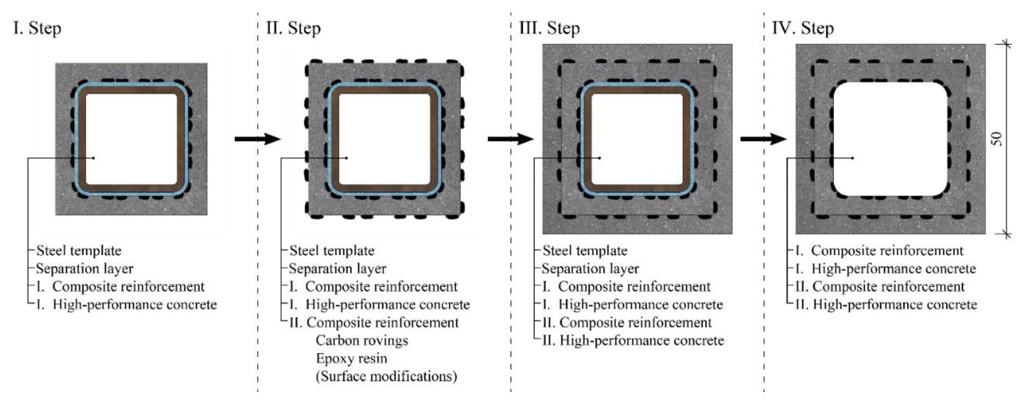
2.2. Specimen Preparation
2.3. Testing Methods
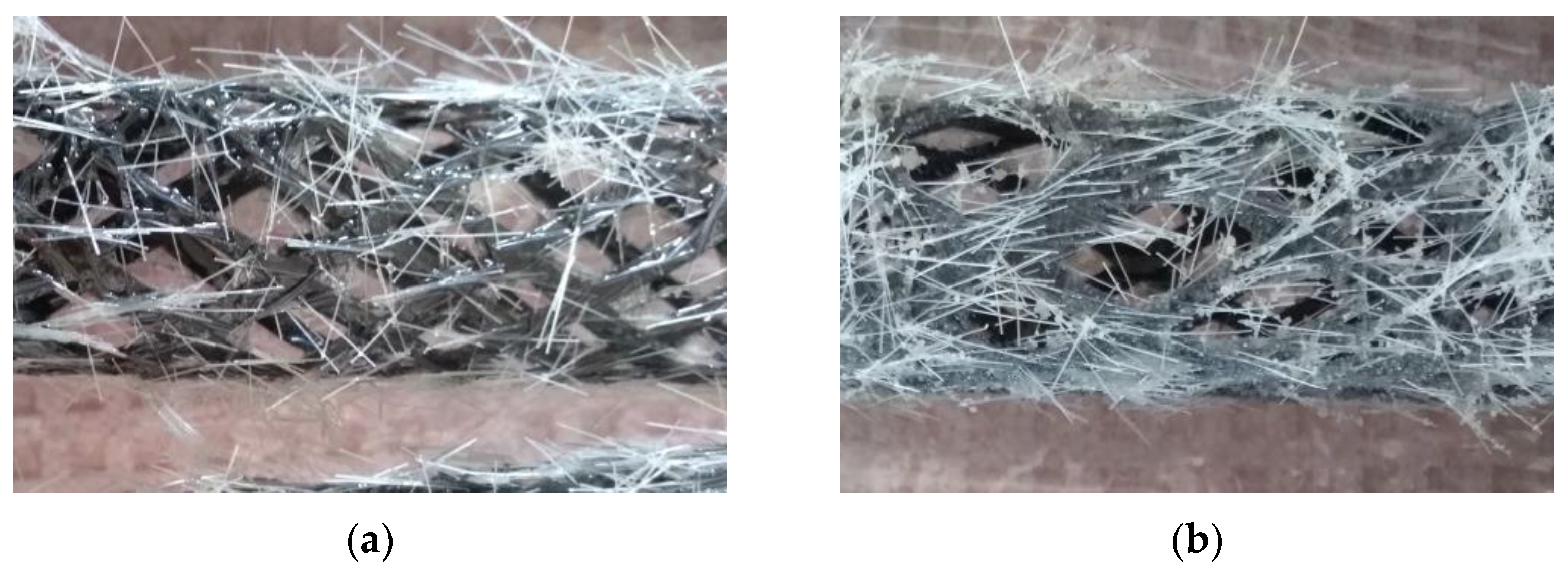
2.3.1. Composite Reinforcement Surface Modifications
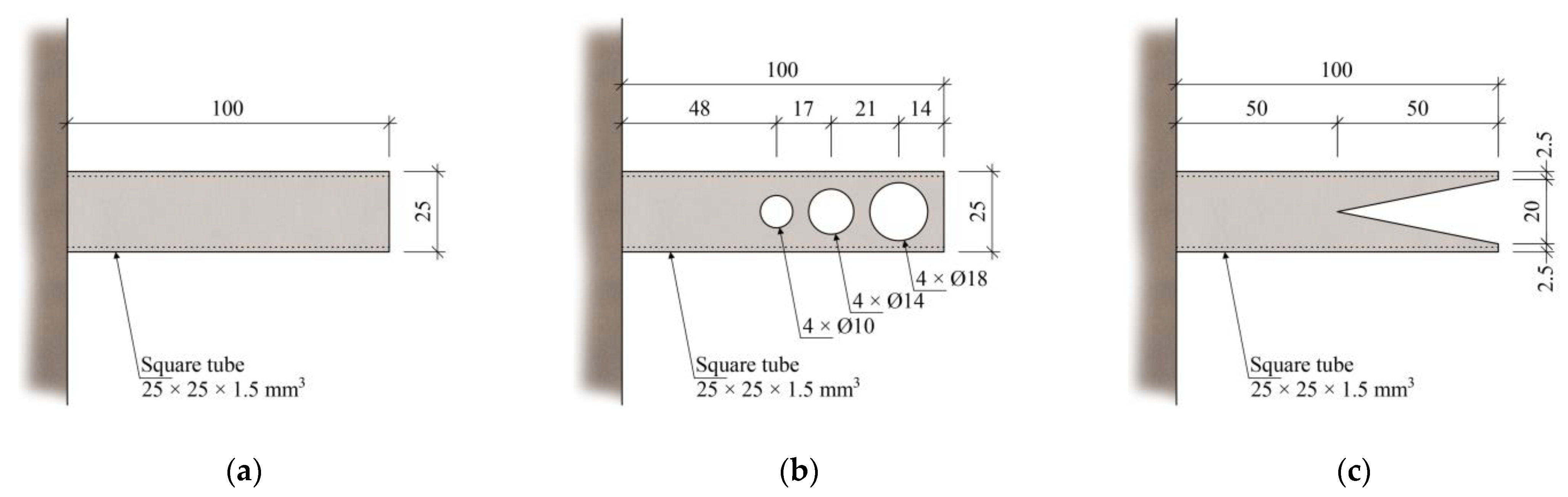
2.3.2. Glued Joints Testing
2.3.3. Multi-Layer Woven Composite Reinforcement
3. Results and Discussion
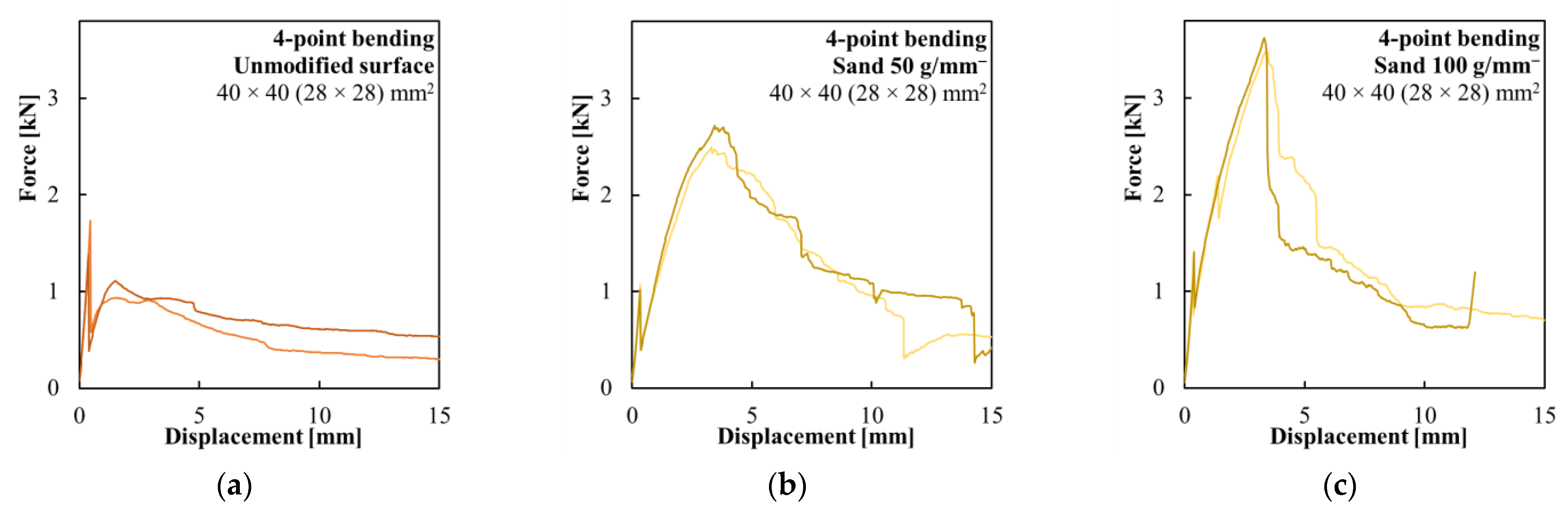
3.1. Composite Reinforcement Surface Modifications
3.2. Glued Joints Testing
3.3. Multi-Layer Woven Composite Reinforcement
4. Application
5. Conclusions
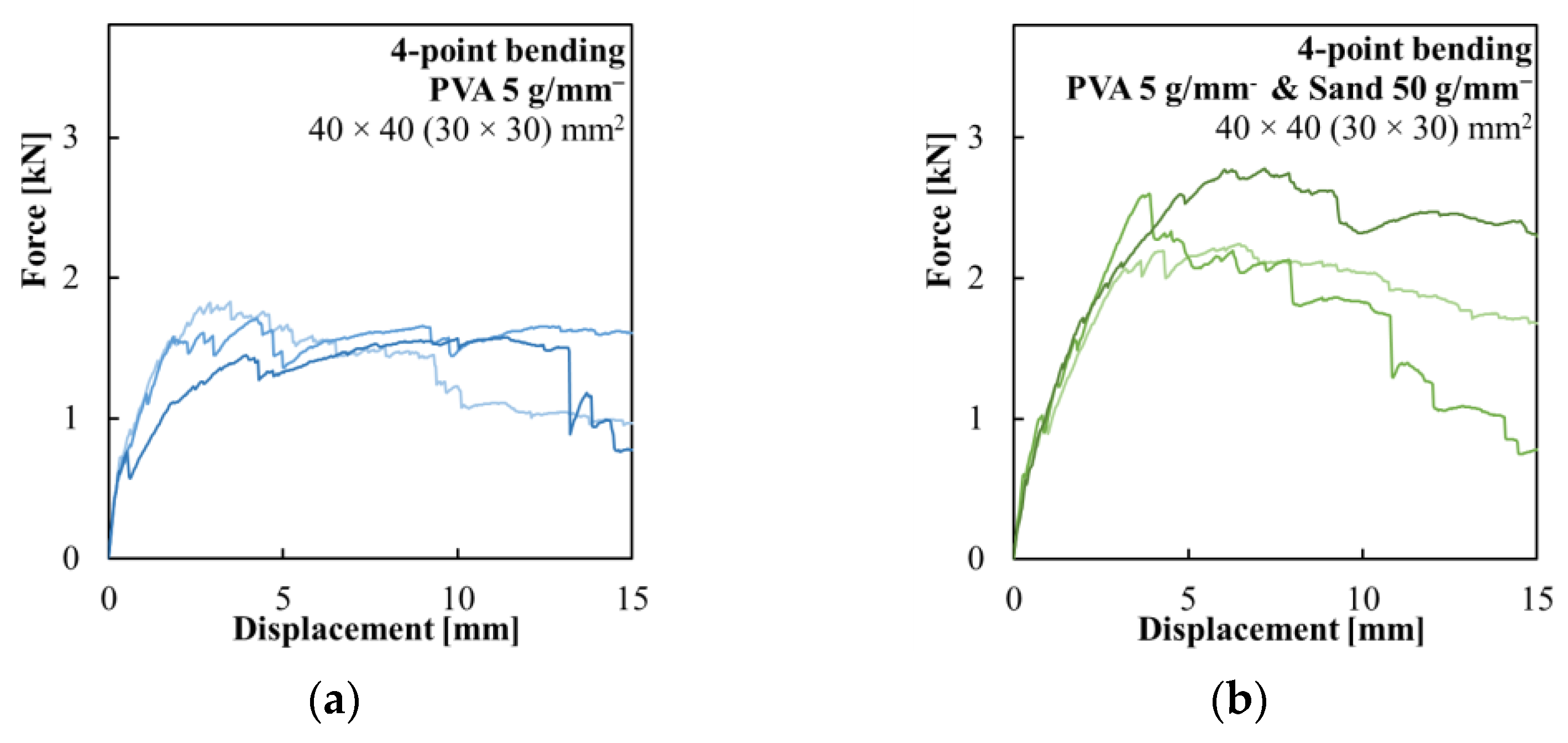
- The proposed surface modifications of the inner woven composite reinforcement proved to have a significant effect on the bending behavior of the hollow beams. The composite reinforcement, without any surface modification, proved unsuitable for any application as the unmodified reinforcement delaminated from the HPC shell after crack development. Coating the surface with either fine-grained silica sand or PVA fibers improved bond strength with the cementitious matrix. The sand coating led to higher flexural strength and more brittle behavior, while the elements with the PVA fibers had lower flexural strength and were more ductile. The use of both surface treatments together resulted in an optimal combination of flexural strength and ductility suitable for the proposed long one-dimensional prefabricated elements.
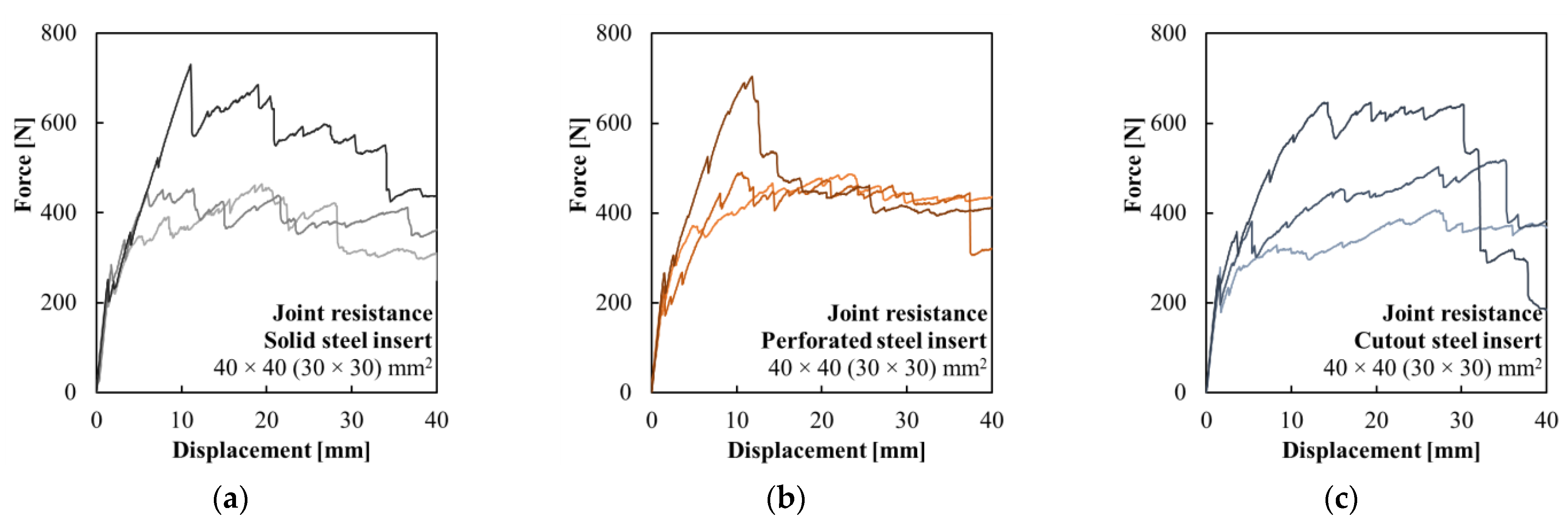
- Experimental loading showed that the glued joints of the hollow HPC beams using a chemical anchor provided a viable solution for connecting them and equipping them with end elements. The glued connection was reliable, and all specimens failed due to the delamination of the composite reinforcement from the inner surface of the hollow HPC beam. The stiffness of the glued steel insert affected the crack development initiation. The lower stiffness of the insert led to higher flexural strength at first crack development.
- The hollow HPC elements reinforced with the multi-layer woven composite reinforcement proved not to be viable with the proposed technology. The additive production technology of weaving carbon rovings directly around previously cast HPC elements, and especially the subsequent impregnation of the rovings using epoxy resin, led to the insufficient interaction of the inner and outer concrete shells, which led to the delamination and early failure of the tested specimens.
- The construction of the small self-supporting structure designed based on the findings of this study demonstrated the feasibility of assembling the hollow concrete elements without the use of mechanization. The use of a chemical anchor for gluing steel joints was proven fast and reliable. The hollow core was also used for the concealed wiring of the LED lights built into the surface of the concrete beams.
6. Patents
Author Contributions
Funding
Institutional Review Board Statement
Informed Consent Statement
Data Availability Statement
Conflicts of Interest
References
- Wichert, M.; Remitz, J.; Empelmann, M. Ultra-High Performance Spun Concrete Poles—Part II: Tests on Grouted Pole Joints. In Proceedings of the 11th High Performance concrete (HPC) and the 2nd Concrete Innovation Conference (CIC), Tromso, Norway, 6–8 March 2017. [Google Scholar]
- Kliukas, R.; Jaras, A.; Lukoševičienė, O. The Impact of Long-Term Physical Salt Attack and Multicycle Temperature Gradient on the Mechanical Properties of Spun Concrete. Materials 2021, 14, 4811. [Google Scholar] [CrossRef] [PubMed]
- Alajarmeh, O.; Manalo, A.; Benmokrane, B.; Ferdous, W.; Mohammed, A.; Abousnina, R.; Elchalakani, M.; Edoo, A. Behavior of circular concrete columns reinforced with hollow composite sections and GFRP bars. Mar. Struct. 2020, 72, 102785. [Google Scholar] [CrossRef]
- Li, G.; Hou, C.; Shen, L.; Yao, G.-H. Performance and strength calculation of CFST columns with localized pitting corrosion damage. J. Constr. Steel Res. 2022, 188, 107011. [Google Scholar] [CrossRef]
- Khamees, S.S.; Kadhum, M.M.; Alwash, N.A. Effect of hollow ratio and cross-section shape on the behavior of hollow SIFCON columns. J. King Saud Univ. —Eng. Sci. 2021, 33, 166–175. [Google Scholar] [CrossRef]
- Abbass, A.A.; Abid, S.R.; Arna’ot, F.H.; Al-Ameri, R.A.; Özakça, M. Flexural response of hollow high strength concrete beams considering different size reductions. Structures 2020, 23, 69–86. [Google Scholar] [CrossRef]
- Ismael, M.A.; Hameed, Y.M. Structural behavior of hollow-core reinforced self-compacting concrete beams. SN Appl. Sci. 2022, 4, 150. [Google Scholar] [CrossRef]
- Abdulhusain, H.M.; Ismael, M.A. Structural Behavior of Hollow Reinforced Concrete Beams: A Review. Diyala J. Eng. Sci. 2020, 13, 91–101. [Google Scholar] [CrossRef]
- Tu’ma, N.H.; Aziz, M.R. Flexural Performance of Composite Ultra-High-Performance Concrete-Encased Steel Hollow Beams. Civ. Eng. J. 2019, 5, 1289–1304. [Google Scholar] [CrossRef]
- Raza, A.; Ali, B.; Masood, B.; ur Rehman, A. Axial performance of GFRP composite bars and spirals in circular hollow concrete columns. Structures 2021, 29, 600–613. [Google Scholar] [CrossRef]
- AlAjarmeh, O.S.; Manalo, A.C.; Benmokrane, B.; Karunasena, W.; Mendis, P.; Nguyen, K.T.Q. Compressive behavior of axially loaded circular hollow concrete columns reinforced with GFRP bars and spirals. Constr. Build. Mater. 2019, 194, 12–23. [Google Scholar] [CrossRef]
- Gouda, M.G.; Mohamed, H.M.; Manalo, A.C.; Benmokrane, B. Experimental investigation of concentrically and eccentrically loaded circular hollow concrete columns reinforced with GFRP bars and spirals. Eng. Struct. 2023, 277, 115442. [Google Scholar] [CrossRef]
- El-Tahan, M.; Galal, K.; Hoa, V.S. New thermoplastic CFRP bendable rebars for reinforcing structural concrete elements. Compos. Part B Eng. 2013, 45, 1207–1215. [Google Scholar] [CrossRef]
- Maranan, G.B.; Manalo, A.C.; Benmokrane, B.; Karunasena, W.; Mendis, P. Behavior of concentrically loaded geopolymer-concrete circular columns reinforced longitudinally and transversely with GFRP bars. Eng. Struct. 2016, 117, 422–436. [Google Scholar] [CrossRef]
- Hao, W.; Liu, Y.; Zhou, H.; Chen, H.; Fang, D. Preparation and characterization of 3D printed continuous carbon fiber reinforced thermosetting composites. Polym. Test. 2018, 65, 29–34. [Google Scholar] [CrossRef]
- Spelter, A.; Bergmann, S.; Bielak, J.; Hegger, J. Long-Term Durability of Carbon-Reinforced Concrete: An Overview and Experimental Investigations. Appl. Sci. 2019, 9, 1651. [Google Scholar] [CrossRef] [Green Version]
- Feng, G.; Zhu, D.; Guo, S.; Rahman, M.Z.; Jin, Z.; Shi, C. A review on mechanical properties and deterioration mechanisms of FRP bars under severe environmental and loading conditions. Cem. Concr. Compos. 2022, 134, 104758. [Google Scholar] [CrossRef]
- EN 1992-1-1; Eurocode 2. Design of Concrete Structures—Part 1-1: General Rules and Rules for Buildings. British Standard Institution: London, UK, 2004.
- Amaro, A.M.; Reis, P.N.B.; Neto, M.A.; Louro, C. Effects of alkaline and acid solutions on glass/epoxy composites. Polym. Degrad. Stab. 2013, 98, 853–862. [Google Scholar] [CrossRef]
- Wang, B.; Li, D.; Xian, G.; Li, C. Effect of Immersion in Water or Alkali Solution on the Structures and Properties of Epoxy Resin. Polymers 2021, 13, 1902. [Google Scholar] [CrossRef]
- Choobbor, S.S.; Hawileh, R.A.; Abu-Obeidah, A.; Abdalla, J.A. Performance of hybrid carbon and basalt FRP sheets in strengthening concrete beams in flexure. Compos. Struct. 2019, 227, 111337. [Google Scholar] [CrossRef]
- Askar, M.K.; Hassan, A.F.; Al-Kamaki, Y.S.S. Flexural and shear strengthening of reinforced concrete beams using FRP composites: A state of the art. Case Stud. Constr. Mater. 2022, 17, e01189. [Google Scholar] [CrossRef]
- Al-Shamayleh, R.; Al-Saoud, H.; Abdel-Jaber, M.; Alqam, M. Shear and flexural strengthening of reinforced concrete beams with variable compressive strength values using externally bonded carbon fiber plates. Results Eng. 2022, 14, 100427. [Google Scholar] [CrossRef]
- Karzad, A.S.; Leblouba, M.; Toubat, S.A.; Maalej, M. Repair and strengthening of shear-deficient reinforced concrete beams using Carbon Fiber Reinforced Polymer. Compos. Struct. 2019, 223, 110963. [Google Scholar] [CrossRef]
- Haroon, M.; Moon, J.S.; Kim, C. Performance of Reinforced Concrete Beams Strengthened with Carbon Fiber Reinforced Polymer Strips. Materials 2021, 14, 5866. [Google Scholar] [CrossRef] [PubMed]
- Vlach, T.; Řepka, J.; Hájek, J.; Jirkalová, Z.; Hájek, P. Panels made of high-performance concrete with surface carbon fabric reinforcement. AIP Conf. Proc. 2021, 2322, 020005. [Google Scholar] [CrossRef]
- Solyom, S.; Balázs, G.L. Bond of FRP bars with different surface characteristics. Constr. Build. Mater. 2020, 264, 119839. [Google Scholar] [CrossRef]
- Baena, M.; Torres, L.; Turon, A.; Barris, C. Experimental study of bond behaviour between concrete and FRP bars using a pull-out test. Compos. Part B Eng. 2009, 40, 784–797. [Google Scholar] [CrossRef]
- Basaran, B.; Kalkan, I. Investigation on variables affecting bond strength between FRP reinforcing bar and concrete by modified hinged beam tests. Compos. Struct. 2020, 242, 112185. [Google Scholar] [CrossRef]
- Li, L.; Li, B.; Wang, Z.; Zhang, Z.; Alselwi, O. Effects of Hybrid PVA–Steel Fibers on the Mechanical Performance of High-Ductility Cementitious Composites. Buildings 2022, 12, 1934. [Google Scholar] [CrossRef]
- Ding, C.; Guo, L.; Chen, B. An optimum polyvinyl alcohol fiber length for reinforced high ductility cementitious composites based on theoretical and experimental analyses. Constr. Build. Mater. 2020, 259, 119824. [Google Scholar] [CrossRef]
- Barhum, R.; Mechtcherine, V. Influence of short dispersed and short integral glass fibres on the mechanical behaviour of textile-reinforced concrete. Mater. Struct. 2013, 46, 557–572. [Google Scholar] [CrossRef]
- Aıtcin, P.C. The durability characteristics of high performance concrete: A review. Cem. Concr. Compos. 2003, 25, 409–420. [Google Scholar] [CrossRef]
- Sohail, M.G.; Kahraman, R.; Al Nuaimi, N.; Gencturk, B.; Alnahhal, W. Durability characteristics of high and ultra-high performance concretes. J. Build. Eng. 2021, 33, 101669. [Google Scholar] [CrossRef]
- EN 12390-3: 2019-07; Testing Hardened Concrete—Part. 3: Compressive strength of Test Specimens. British Standard Institution: London, UK, 2019.
- EN 12390-5: 2019-08; Testing Hardened Concrete—Part 5: Flexural Strength of Test Specimens. British Standard Institution: London, UK, 2019.
- ISO 1920-10:2010; Testing of Concrete—Part 10: Determination of static Modulus of Elasticity in Compression. ISO: Geneva, Switzerland, 2010.
- Teijin®, Product Data Sheet: TenaxTM-J/E STS40 F13 24K 1600tex. Available online: https://www.teijincarbon.com/fileadmin/PDF/Datenbl%C3%A4tter_dt/Product_Data_Sheet_TSG01de__EU_Filament___DE_.pdf (accessed on 1 June 2023).
- Sika®, Product Data Sheet: SikaFloor®-156. Available online: https://gbr.sika.com/dms/getdocument.get/a7b1958e-a112-3fa3-90a3-4e5263877aeb/Sikafloor%20156.pdf (accessed on 2 March 2023).
- D’Antino, T.; Papanicolaou, C. Mechanical characterization of textile reinforced inorganic-matrix composites. Compos. Part B Eng. 2017, 127, 78–91. [Google Scholar] [CrossRef]
- Sklopísek Střeleč, a.s. Product Data Sheet: ST 01/06. Available online: https://en.glassand.eu/getFile/case:show/id:438223?? (accessed on 11 July 2023).


| Component | [kg/m3] |
|---|---|
| Cement I 42.5 R | 680 |
| Technical silica sand | 960 |
| Silica flour | 325 |
| Silica fume | 175 |
| Superplasticizers | 29 |
| Water | 171 |
| Series | Amt. | Elastic Section Modulus [mm3] | First-Cracking Load [N] | First-Cracking Stress [MPa] | Ultimate Loading Force [N] |
|---|---|---|---|---|---|
| Unmodified surface | 2 | 8932 ± 163 (100%) | 1557.6 ± 174.5 (100%) | 8.70 ± 0.82 (100%) | 1557.6 ± 174.5 (100%) |
| Silica sand 50 g/m− | 2 | 9239 ± 18 (103%) | 1046.1 ± 27.7 (67%) | 5.66 ± 0.14 (65%) | 2607.0 ± 114.2 (167%) |
| Silica sand 100 g/m− | 2 | 9070 ± 277 (102%) | 1338.2 ± 68.1 (86%) | 7.39 ± 0.60 (85%) | 3555.7 ± 66.6 (228%) |
| PVA fibers 5 g/m− | 3 | 9133 ± 441 (102%) | 689.3 ± 45.5 (44%) | 3.78 ± 0.23 (43%) | 1705.4 ± 104.3 (110%) |
| PVA fibers + Silica sand | 3 | 8777 ± 329 (98%) | 612.8 ± 45.5 (39%) | 3.49 ± 0.23 (40%) | 2549.5 ± 225.2 (164%) |
| Series | Amt. | Elastic Section Modulus [mm3] | First-Cracking Load [N] | First-Cracking Stress [MPa] | Ultimate Loading Force [N] |
|---|---|---|---|---|---|
| Solid steel insert | 3 | 8712 ± 187 (100%) | 256.1 ± 21.7 (100%) | 6.02 ± 0.38 (100%) | 550.0 ± 128.1 (100%) |
| Perforated steel insert | 3 | 8122 ± 504 (93%) | 229.3 ± 26.8 (90%) | 5.79 ± 0.58 (96%) | 560.5 ± 101.9 (102%) |
| Cutout steel insert | 3 | 8397 ± 98 (96%) | 264.8 ± 10.9 (103%) | 6.46 ± 0.28 (107%) | 524.0 ± 97.7 (95%) |
| Series | Amt. | Elastic Section Modulus [mm3] | First-Cracking Load [N] | First-Cracking Stress [MPa] | Ultimate Loading Force [N] |
|---|---|---|---|---|---|
| One layer 24 rovings | 4 | 21,699 ± 759 (100%) | 5613.6 ± 887.1 (100%) | 7.75 ± 1.09 (100%) | 6189.4 ± 1754.1 (100%) |
| Two layers 24 rovings | 3 | 21,726 ± 118 (100%) | 2648.3 ± 288.5 (47%) | 3.65 ± 0.38 (47%) | 6674.3 ± 1156.9 (108%) |
| One layer 36 rovings | 4 | 20,763 ± 930 (100%) | 5440.6 ± 940.9 (100%) | 7.87 ± 1.38 (100%) | 5702.3 ± 1202.7 (100%) |
| Two layers 36 rovings | 3 | 21,271 ± 1121 (102%) | 4224.8 ± 273.7 (78%) | 5.99 ± 0.66 (76%) | 5652.1 ± 141.1 (99%) |
Disclaimer/Publisher’s Note: The statements, opinions and data contained in all publications are solely those of the individual author(s) and contributor(s) and not of MDPI and/or the editor(s). MDPI and/or the editor(s) disclaim responsibility for any injury to people or property resulting from any ideas, methods, instructions or products referred to in the content. |
© 2023 by the authors. Licensee MDPI, Basel, Switzerland. This article is an open access article distributed under the terms and conditions of the Creative Commons Attribution (CC BY) license (https://creativecommons.org/licenses/by/4.0/).
Share and Cite
Řepka, J.; Vlach, T.; Hájek, J.; Fürst, R.; Pošta, J.; Hájek, P. Woven Carbon-Fiber-Reinforced Polymer Tubular Mesh Reinforcement of Hollow High-Performance Concrete Beams. Polymers 2023, 15, 3089. https://doi.org/10.3390/polym15143089
Řepka J, Vlach T, Hájek J, Fürst R, Pošta J, Hájek P. Woven Carbon-Fiber-Reinforced Polymer Tubular Mesh Reinforcement of Hollow High-Performance Concrete Beams. Polymers. 2023; 15(14):3089. https://doi.org/10.3390/polym15143089
Chicago/Turabian StyleŘepka, Jakub, Tomáš Vlach, Jakub Hájek, Richard Fürst, Jan Pošta, and Petr Hájek. 2023. "Woven Carbon-Fiber-Reinforced Polymer Tubular Mesh Reinforcement of Hollow High-Performance Concrete Beams" Polymers 15, no. 14: 3089. https://doi.org/10.3390/polym15143089