
Bone Formation on Murine Cranial Bone by Injectable Cross-Linked Hyaluronic Acid Containing Nano-Hydroxyapatite and Bone Morphogenetic Protein
 and
and
Abstract
:1. Introduction
2. Materials and Methods
2.1. Material
2.2. Material Constitution and Experimental Design
2.3. Material Characterization of Control HyA, ux-tHyA, and x-tHyA
2.3.1. FTIR
2.3.2. SEM
2.3.3. Hyaluronidase Dissolution Tests
2.3.4. TG/DSC Thermal Analyses
2.4. Characterization of the Use of nHAp
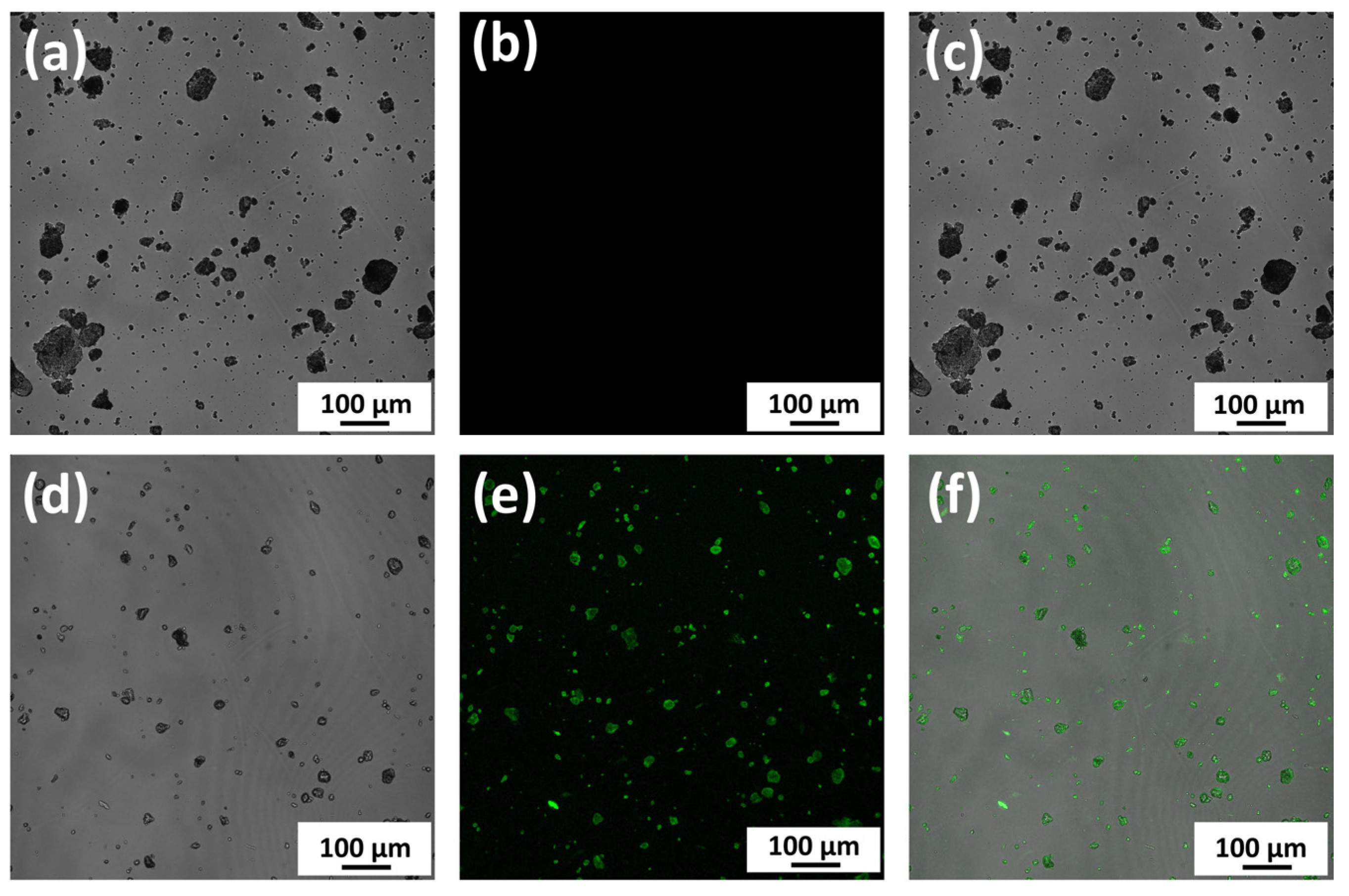
2.4.1. Observation of Binding between nHAp and Protein
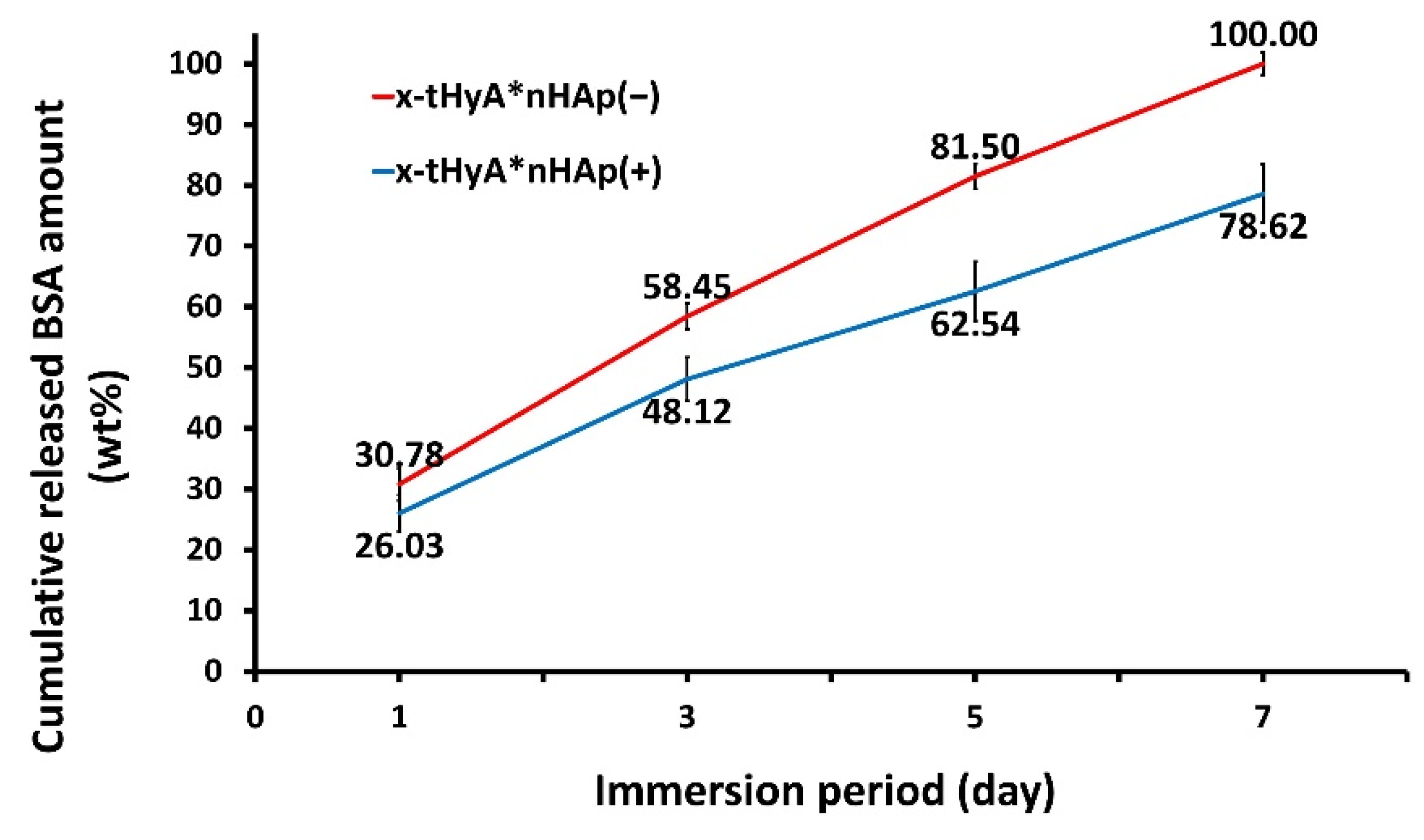
2.4.2. Accelerated Protein Release Tests from x-tHyA Containing nHAp
2.5. Preparation of SG I and SG II Materials
2.5.1. SG I Sample
2.5.2. SG II Sample
2.6. Animal Experiments
2.6.1. SG I Sample
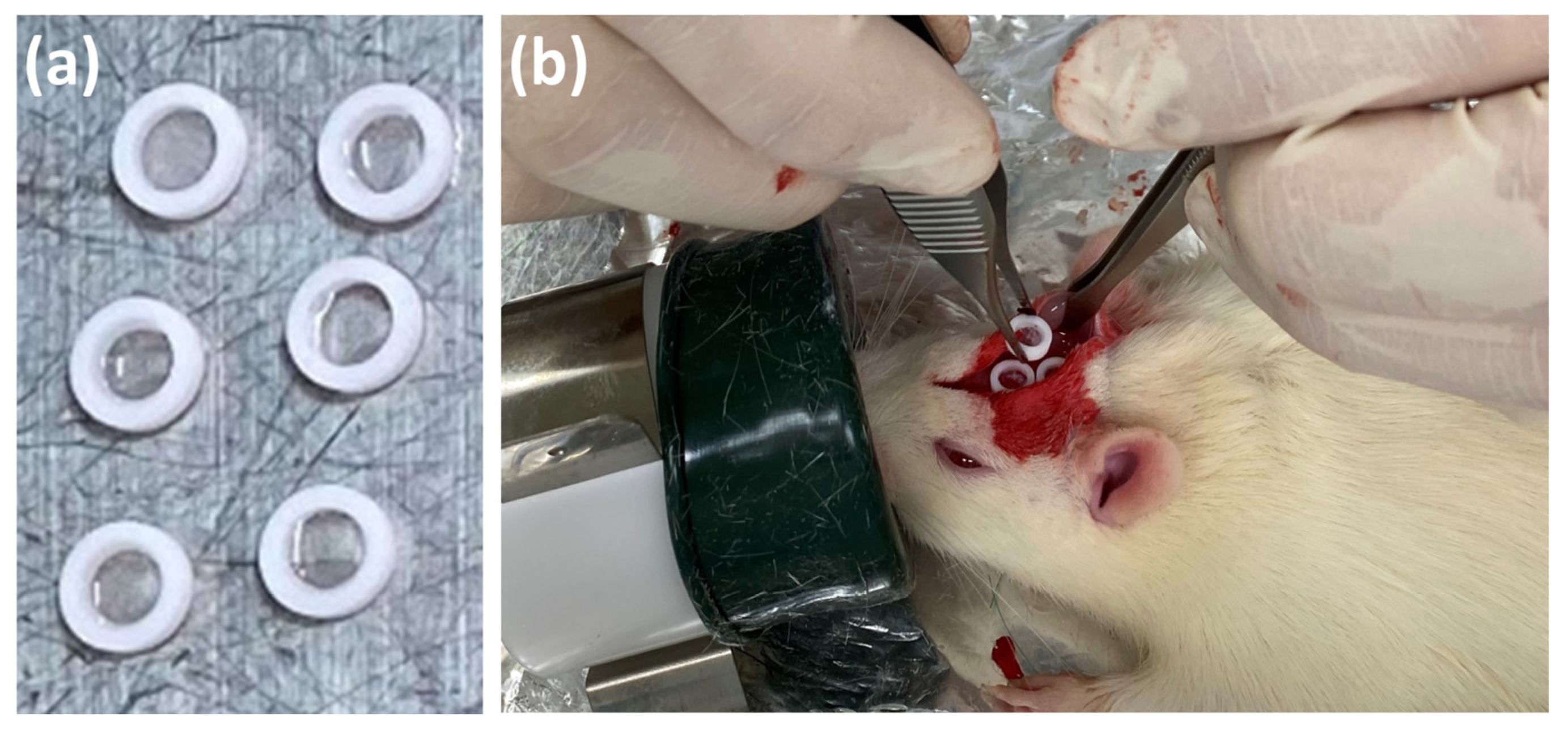
2.6.2. SG II Sample
2.6.3. X-ray Analyses
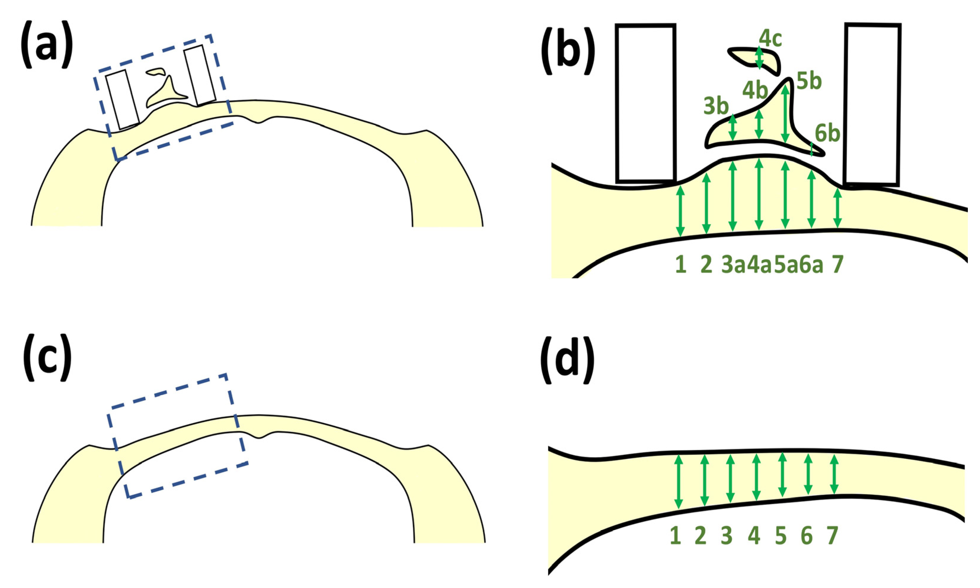
2.6.4. Histological Observations
2.7. Statistical Analyses
3. Results
3.1. Material Characterization of HyA Control, ux-tHyA, and x-tHyA
3.1.1. FTIR
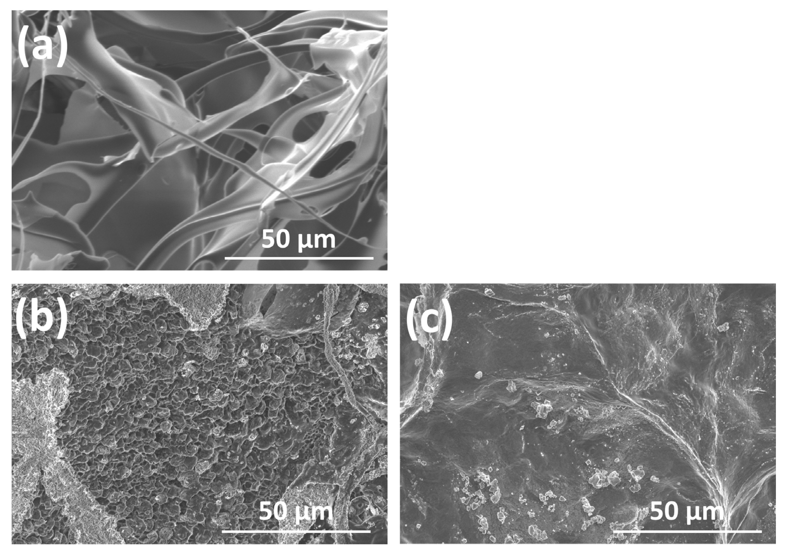
3.1.2. SEM Observations
3.1.3. Hyaluronidase Dissolution Tests
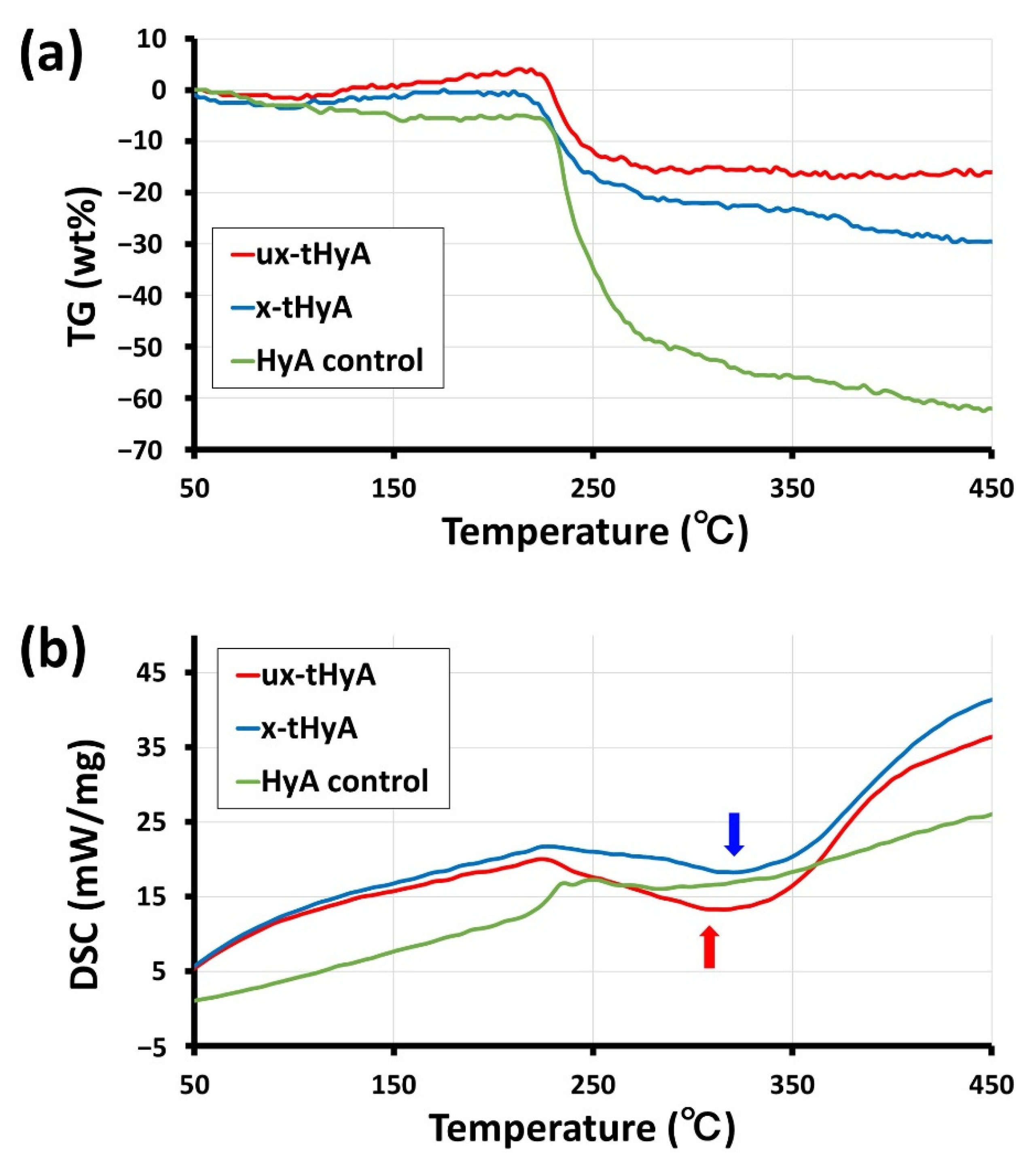
3.1.4. TG/DSC
3.2. Characterization of the Use of nHAp
3.2.1. Observation of Direct Binding between nHAp and Protein
3.2.2. Accelerated Protein Release Test
3.3. Animal Studies
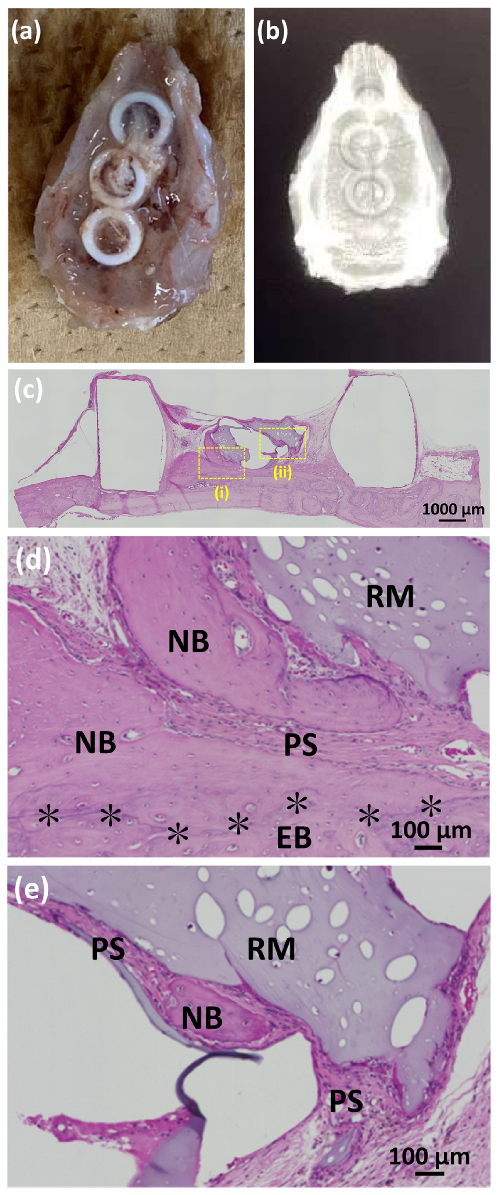
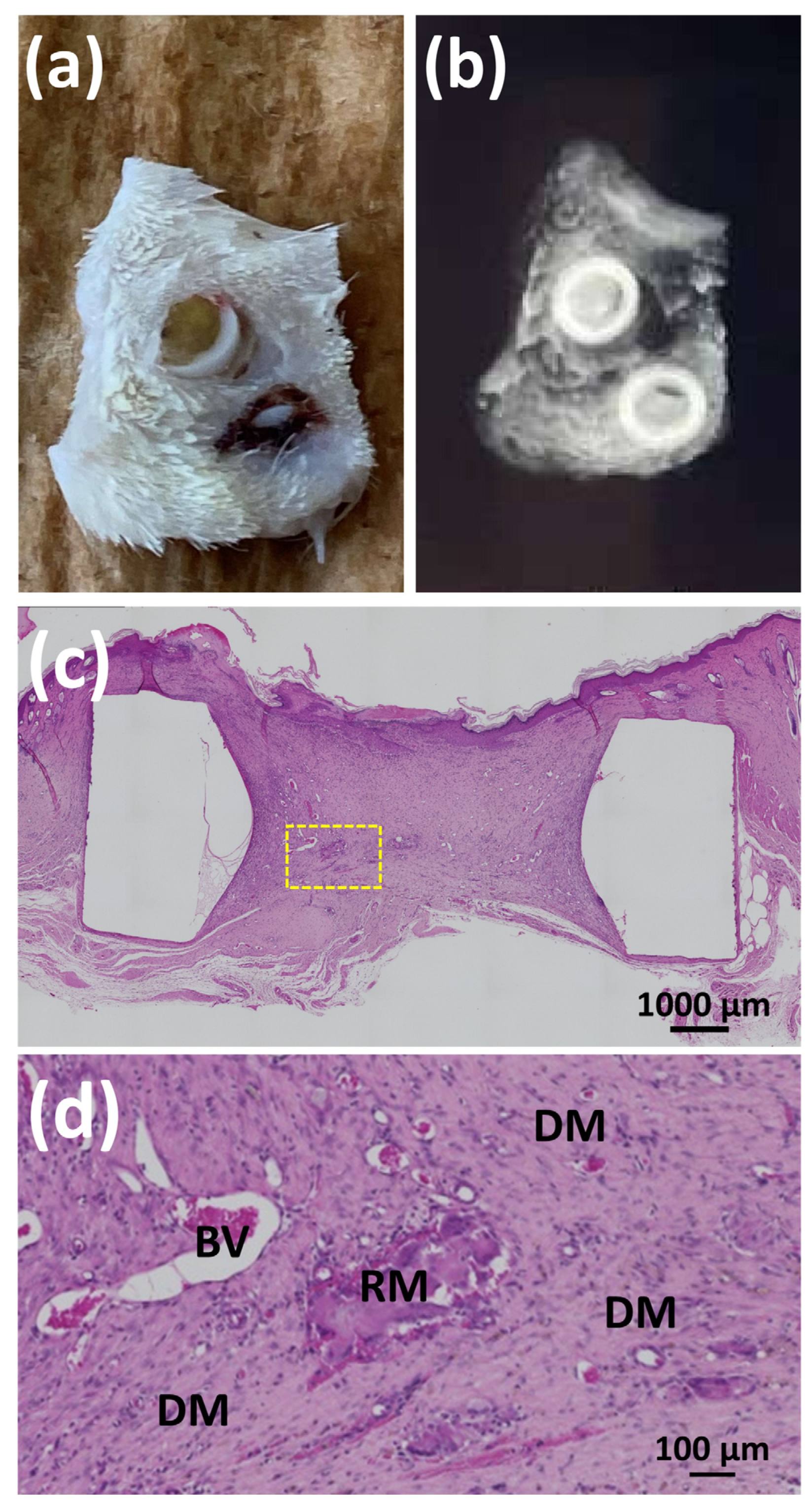
3.3.1. Animal Experiments with SG I
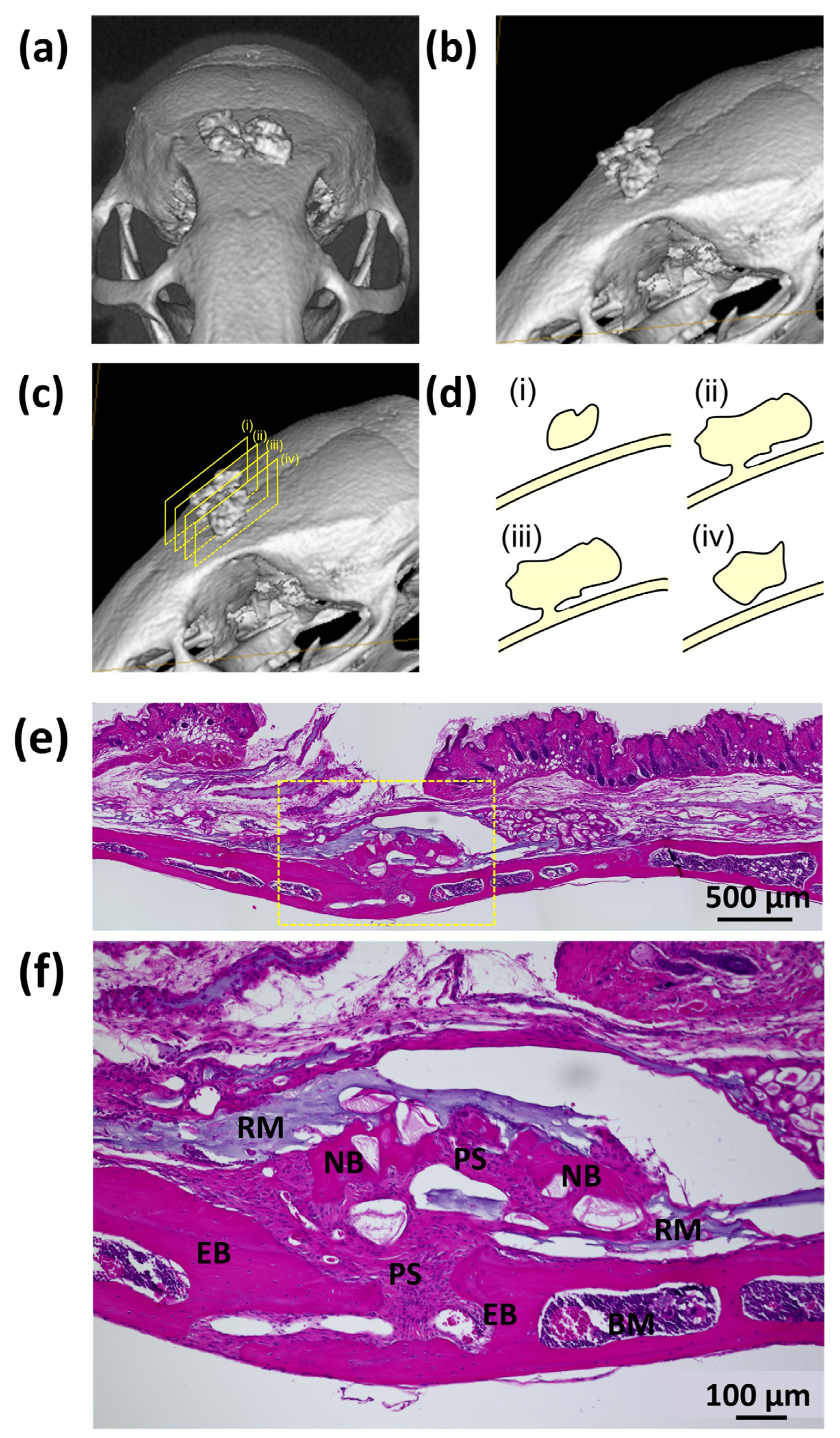
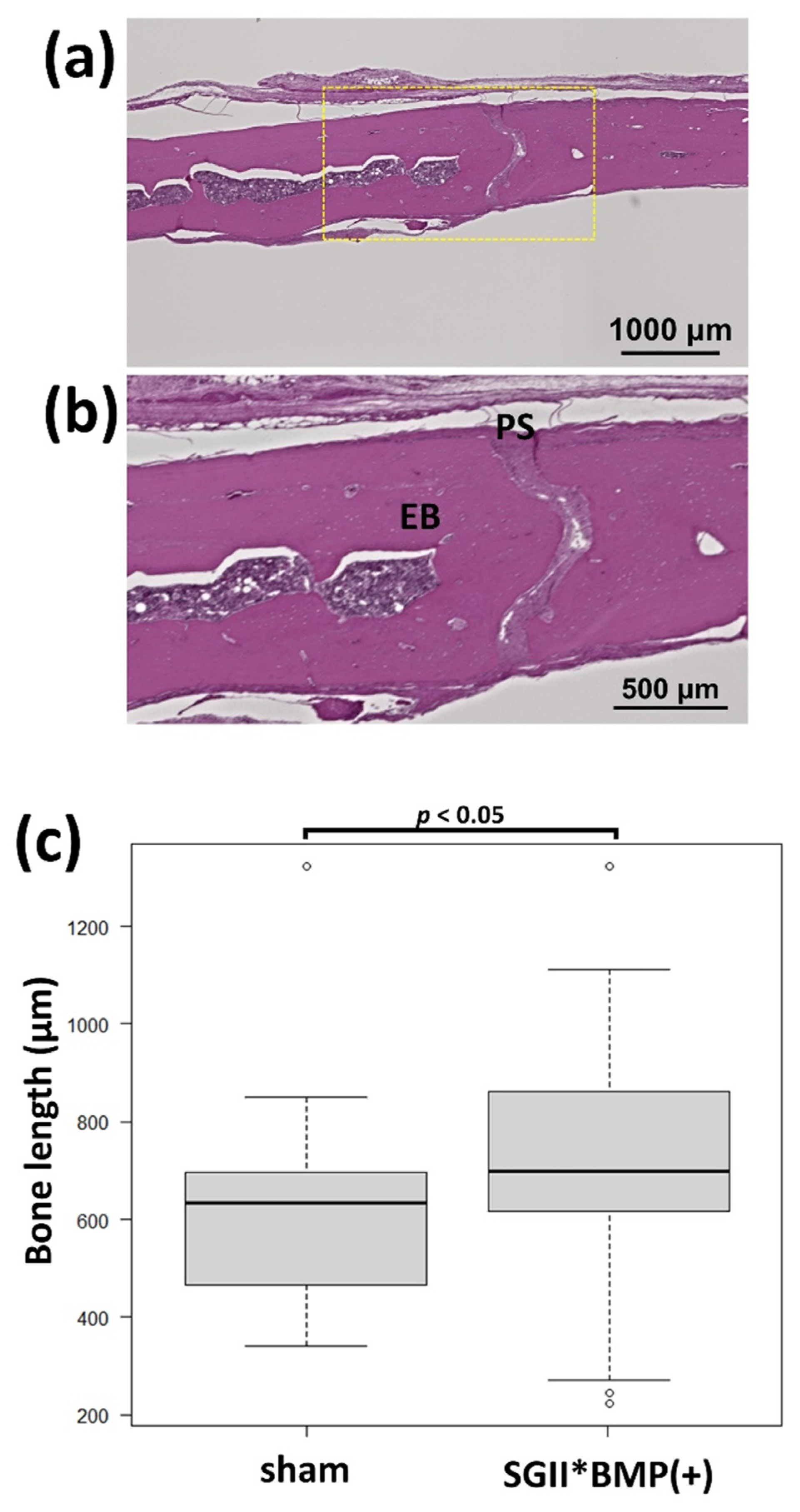
3.3.2. Animal Experiments with SG II
4. Discussion
5. Conclusions
- (1)
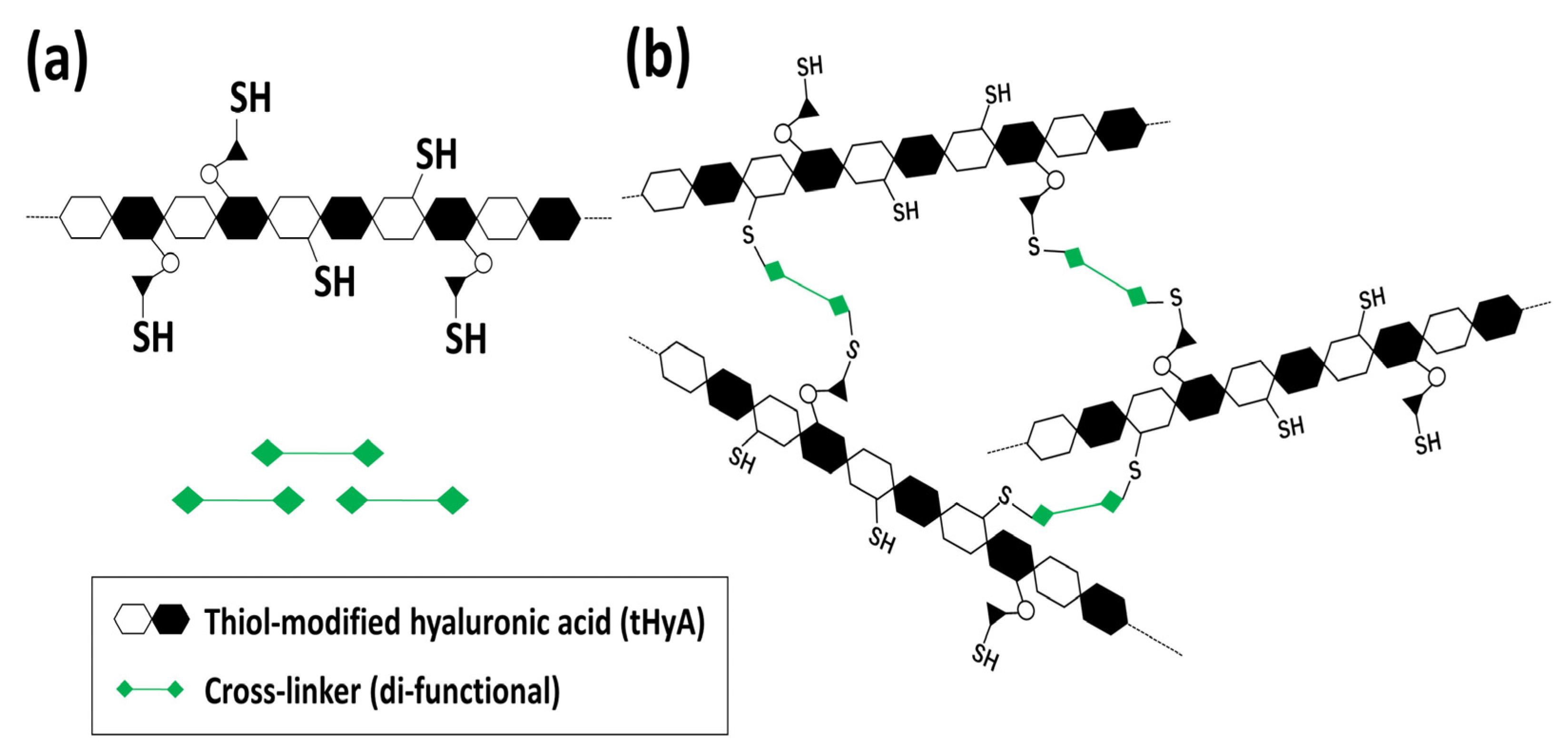
- Instrumental analyses (FTIR, TG/DSC, and SEM) confirmed the presence of thiol modifications and characteristic cross-linking reactions. The cross-linked structure appeared to result in a considerably long hyaluronidase dissolution time and a denser/plain microstructure upon freeze-drying.
- (2)
- We confirmed that nHAp is directly bound to proteins and could play an important role as a growth factor carrier to hold and release proteins for a long period, which is beneficial for sustaining the time required bone formation.
- (3)
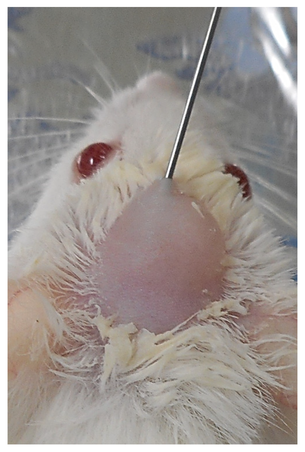
- BMP is a strong bone-forming growth factor. However, its application must be localized to osseous sites for clinically significant bone augmentation. BMP easily causes undesirable ectopic bone formation when applied to connective soft tissues. It is highly anticipated that a technique will be developed for the precise subperiosteal injection of bone-forming SG materials.
- (4)
- The combined use of nHAp and BMP for x-tHyA succeeded in bone formation at the rate of 70−83%, achieving a relatively high positive record. The dual use of nHAp and BMP is vital for successful bone formation.
- (5)
- Because the materials used (x-HyA, nHAp, and BMP) are widely available, it is highly desirable to develop a new injectable bone-forming system consisting of these materials for widespread clinical use soon.
Author Contributions
Funding
Institutional Review Board Statement
Data Availability Statement
Acknowledgments
Conflicts of Interest
Abbreviations
| BMP | Bone morphogenetic protein |
| BV | blood vessels |
| DG water | Degassed water |
| DM | Dermal tissues |
| DSC | Differential scanning calorimetry |
| EB | Existing bone |
| FTIR | Fourier-transformed infrared spectroscopy |
| HAp | Hydroxyapatite |
| HE | Hematoxylin and eosin |
| HyA | Hyaluronic acid |
| micro-CT | Micro-computed tomography |
| NB | New bone |
| nHAp | Nano-hydroxyapatite |
| PEGDA | Polyethylene glycol diacryalate |
| PS | Periosteum |
| RM | Residual material |
| SEM | Scanning electron microscopy |
| TG | Thermogravimetric analysis |
| ux-tHyA | Un-cross-linked thiol-modified hyaluronic acid |
| x-tHyA | Cross-linked thiol-modified hyaluronic acid |
References
- Zhang, W.; Tullis, J.; Weltman, R. Cone Beam Computerized Tomography Measurement of Alveolar Ridge at Posterior Mandible for Implant Graft Estimation. J. Oral Implant. 2015, 41, e231–e237. [Google Scholar] [CrossRef] [PubMed] [Green Version]
- Yamada, M.; Egusa, H. Current bone substitutes for implant dentistry. J. Prosthodont. Res. 2018, 62, 152–161. [Google Scholar] [CrossRef] [PubMed]
- Sheikh, Z.; Sima, C.; Glogauer, M. Bone Replacement Materials and Techniques Used for Achieving Vertical Alveolar Bone Augmentation. Materials 2015, 8, 2953–2993. [Google Scholar] [CrossRef]
- Roca-Millan, E.; Jané-Salas, E.; Marí-Roig, A.; Jiménez-Guerra, A.; Ortiz-García, I.; Velasco-Ortega, E.; López-López, J.; Monsalve-Guil, L. The Application of Beta-Tricalcium Phosphate in Implant Dentistry: A Systematic Evaluation of Clinical Studies. Materials 2022, 15, 655. [Google Scholar] [CrossRef] [PubMed]
- El Deeb, M.E.; Tompach, P.C.; Morstad, A.T. Porous hydroxylapatite granules and blocks as alveolar ridge augmentation materials: A preliminary report. J. Oral Maxillofac. Surg. 1988, 46, 955–970. [Google Scholar] [CrossRef]
- Ishikawa, K.; Hayashi, K. Carbonate apatite artificial bone. Sci. Technol. Adv. Mater. 2021, 22, 683–694. [Google Scholar] [CrossRef]
- El Deeb, M. Comparison of three methods of stabilization of particulate hydroxylapatite for augmentation of the mandibular ridge. J. Oral Maxillofac. Surg. 1988, 46, 758–766. [Google Scholar] [CrossRef] [PubMed]
- Tomas, M.; Čandrlić, M.; Juzbašić, M.; Ivanišević, Z.; Matijević, N.; Včev, A.; Peloza, O.C.; Matijević, M.; Kačarević, P. Synthetic Injectable Biomaterials for Alveolar Bone Regeneration in Animal and Human Studies. Materials 2021, 14, 2858. [Google Scholar] [CrossRef]
- Yang, H.; Zou, J. Filling Materials Used in Kyphoplasty and Vertebroplasty for Vertebral Compression Fracture: A Literature Review. Artif. Cells Blood Substit. Biotechnol. 2010, 39, 87–91. [Google Scholar] [CrossRef]
- Shi, J.; Yu, L.; Ding, J. PEG-based thermosensitive and biodegradable hydrogels. Acta Biomater. 2021, 128, 42–59. [Google Scholar] [CrossRef]
- Peers, S.; Montembault, A.; Ladavière, C. Chitosan hydrogels incorporating colloids for sustained drug delivery. Carbohydr. Polym. 2021, 275, 118689. [Google Scholar] [CrossRef] [PubMed]
- Xu, M.; Qin, M.; Cheng, Y.; Niu, X.; Kong, J.; Zhang, X.; Huang, D.; Wang, H. Alginate microgels as delivery vehicles for cell-based therapies in tissue engineering and regenerative medicine. Carbohydr. Polym. 2021, 266, 118128. [Google Scholar] [CrossRef] [PubMed]
- Feng, J.; Mineda, K.; Wu, S.-H.; Mashiko, T.; Doi, K.; Kuno, S.; Kinoshita, K.; Kanayama, K.; Asahi, R.; Sunaga, A.; et al. An injectable non-cross-linked hyaluronic-acid gel containing therapeutic spheroids of human adipose-derived stem cells. Sci. Rep. 2017, 7, 1548. [Google Scholar] [CrossRef] [PubMed]
- Fujioka-Kobayashi, M.; Schaller, B.; Kobayashi, E.; Hernandez, M.; Zhang, Y.; Miron, R.J. Hyaluronic Acid Gel-Based Scaffolds as Potential Carrier for Growth Factors: An In Vitro Bioassay on Its Osteogenic Potential. J. Clin. Med. 2016, 5, 112. [Google Scholar] [CrossRef] [PubMed] [Green Version]
- Kim, D.-S.; Kim, J.H.; Baek, S.-W.; Lee, J.-K.; Park, S.-Y.; Choi, B.; Kim, T.-H.; Min, K.; Han, D.K. Controlled vitamin D delivery with injectable hyaluronic acid-based hydrogel for restoration of tendinopathy. J. Tissue Eng. 2022, 13, 20417314221122089. [Google Scholar] [CrossRef] [PubMed]
- Kimura, A.; Kabasawa, Y.; Tabata, Y.; Aoki, K.; Ohya, K.; Omura, K. Gelatin Hydrogel as a Carrier of Recombinant Human Fibroblast Growth Factor-2 During Rat Mandibular Distraction. J. Oral Maxillofac. Surg. 2014, 72, 2015–2031. [Google Scholar] [CrossRef]
- Uehara, T.; Mise-Omata, S.; Matsui, M.; Tabata, Y.; Murali, R.; Miyashin, M.; Aoki, K. Delivery of RANKL-Binding Peptide OP3-4 Promotes BMP-2–Induced Maxillary Bone Regeneration. J. Dent. Res. 2016, 95, 665–672. [Google Scholar] [CrossRef]
- Lorenz, J.; Barbeck, M.; Kirkpatrick, C.; Sader, R.; Lerner, H.; Ghanaati, S. Injectable Bone Substitute Material on the Basis of β-TCP and Hyaluronan Achieves Complete Bone Regeneration While Undergoing Nearly Complete Degradation. Int. J. Oral Maxillofac. Implant. 2018, 33, 636–644. [Google Scholar] [CrossRef]
- Martínez-Sanz, E.; Varghese, O.P.; Kisiel, M.; Engstrand, T.; Reich, K.M.; Bohner, M.; Jonsson, K.B.; Kohler, T.; Müller, R.; Ossipov, D.A.; et al. Minimally invasive mandibular bone augmentation using injectable hydrogels. J. Tissue Eng. Regen. Med. 2012, 6 (Suppl. S3), s15–s23. [Google Scholar] [CrossRef]
- Chircov, C.; Grumezescu, A.M.; Bejenaru, L.E. Hyaluronic acid-based scaffolds for tissue engineering. Rom. J. Morphol. Embryol. 2018, 59, 71–76. Available online: https://rjme.ro/RJME/resources/files/590118071076.pdf (accessed on 10 November 2022).
- Salwowska, N.M.; Bebenek, K.A.; Żądło, D.A.; Wcisło-Dziadecka, D.L. Physiochemical properties and application of hyaluronic acid: A systematic review. J. Cosmet. Dermatol. 2016, 15, 520–526. [Google Scholar] [CrossRef] [PubMed]
- Peng, T.; Hong, W.; Fang, J.; Luo, S. The selection of hyaluronic acid when treating with the nasolabial fold: A meta-analysis. J. Cosmet. Dermatol. 2022, 21, 571–579. [Google Scholar] [CrossRef] [PubMed]
- Wu, Y.; Stoddart, M.; Wuertz-Kozak, K.; Grad, S.; Alini, M.; Ferguson, S. Hyaluronan supplementation as a mechanical regulator of cartilage tissue development under joint-kinematic-mimicking loading. J. R. Soc. Interface 2017, 14, 20170255. [Google Scholar] [CrossRef] [PubMed]
- Durrie, D.S.; Wolsey, D.; Thompson, V.; Assang, C.; Mann, B.; Wirostko, B. Ability of a new crosslinked polymer ocular bandage gel to accelerate reepithelialization after photorefractive keratectomy. J. Cataract. Refract. Surg. 2018, 44, 369–375. [Google Scholar] [CrossRef] [PubMed]
- Jiang, D.; Liang, J.; Noble, P.W. Hyaluronan in Tissue Injury and Repair. Annu. Rev. Cell Dev. Biol. 2007, 23, 435–461. [Google Scholar] [CrossRef] [Green Version]
- Canciani, E.; Sirello, R.; Pellegrini, G.; Henin, D.; Perrotta, M.; Toma, M.; Khomchyna, N.; Dellavia, C. Effects of Vitamin and Amino Acid-Enriched Hyaluronic Acid Gel on the Healing of Oral Mucosa: In Vivo and In Vitro Study. Medicina 2021, 57, 285. [Google Scholar] [CrossRef] [PubMed]
- Buckley, C.; Murphy, E.J.; Montgomery, T.R.; Major, I. Hyaluronic Acid: A Review of the Drug Delivery Capabilities of This Naturally Occurring Polysaccharide. Polymers 2022, 14, 3442. [Google Scholar] [CrossRef]
- Martínez-Sanz, E.; Ossipov, D.A.; Hilborn, J.; Larsson, S.; Jonsson, K.B.; Varghese, O.P. Bone reservoir: Injectable hyaluronic acid hydrogel for minimal invasive bone augmentation. J. Control. Release 2011, 152, 232–240. [Google Scholar] [CrossRef]
- Hulsart-Billström, G.; Bergman, K.; Andersson, B.; Hilborn, J.; Larsson, S.; Jonsson, K.B. A uni-cortical femoral defect model in the rat: Evaluation using injectable hyaluronan hydrogel as a carrier for bone morphogenetic protein-2. J. Tissue Eng. Regen. Med. 2012, 9, 799–807. [Google Scholar] [CrossRef]
- Patterson, J.; Siew, R.; Herring, S.W.; Lin, A.S.; Guldberg, R.; Stayton, P. Hyaluronic acid hydrogels with controlled degradation properties for oriented bone regeneration. Biomaterials 2010, 31, 6772–6781. [Google Scholar] [CrossRef] [Green Version]
- Pike, D.B.; Cai, S.; Pomraning, K.R.; Firpo, M.A.; Fisher, R.J.; Shu, X.Z.; Prestwich, G.D.; Peattie, R.A. Heparin-regulated release of growth factors in vitro and angiogenic response in vivo to implanted hyaluronan hydrogels containing VEGF and bFGF. Biomaterials 2006, 27, 5242–5251. [Google Scholar] [CrossRef] [PubMed]
- Summonte, S.; Racaniello, G.F.; Lopedota, A.; Denora, N.; Bernkop-Schnürch, A. Thiolated polymeric hydrogels for biomedical application: Cross-linking mechanisms. J. Control. Release 2020, 330, 470–482. [Google Scholar] [CrossRef] [PubMed]
- Zarembinski, T.I.; Skardal, A. HyStem®: A Unique Clinical Grade Hydrogel for Present and Future Medical Applications. In Hydrogels-Smart Materials for Biomedical Applications; Popa, L., Ghica, M.V., Dinu-Pîrvu, C., Eds.; IntechOpen: London, UK, 2019. [Google Scholar] [CrossRef] [Green Version]
- Ogasawara, T.; Okano, S.; Ichimura, H.; Kadota, S.; Tanaka, Y.; Minami, I.; Uesugi, M.; Wada, Y.; Saito, N.; Okada, K.; et al. Impact of extracellular matrix on engraftment and maturation of pluripotent stem cell-derived cardiomyocytes in a rat myocardial infarct model. Sci. Rep. 2017, 7, 1–8. [Google Scholar] [CrossRef] [PubMed] [Green Version]
- Maloney, E.; Clark, C.; Sivakumar, H.; Yoo, K.; Aleman, J.; Rajan, S.A.P.; Forsythe, S.; Mazzocchi, A.; Laxton, A.W.; Tatter, S.B.; et al. Immersion Bioprinting of Tumor Organoids in Multi-Well Plates for Increasing Chemotherapy Screening Throughput. Micromachines 2020, 11, 208. [Google Scholar] [CrossRef] [PubMed] [Green Version]
- Glickman, R.D.; Onorato, M.; Campos, M.M.; O’Boyle, M.P.; Singh, R.K.; Zarembinski, T.I.; Binette, F.; Nasonkin, I.O. Intraocular Injection of HyStem Hydrogel Is Tolerated Well in the Rabbit Eye. J. Ocul. Pharmacol. Ther. 2021, 37, 60–71. [Google Scholar] [CrossRef] [PubMed]
- Ravina, K.; Briggs, D.I.; Kislal, S.; Warraich, Z.; Nguyen, T.; Lam, R.K.; Zarembinski, T.I.; Shamloo, M. Intracerebral Delivery of Brain-Derived Neurotrophic Factor Using HyStem®-C Hydrogel Implants Improves Functional Recovery and Reduces Neuroinflammation in a Rat Model of Ischemic Stroke. Int. J. Mol. Sci. 2018, 19, 3782. [Google Scholar] [CrossRef] [Green Version]
- AlHowaish, N.A.; AlSudani, D.I.; AlMuraikhi, N.A. Evaluation of a hyaluronic acid hydrogel (Restylane Lyft) as a scaffold for dental pulp regeneration in a regenerative endodontic organotype model. Odontology 2022, 110, 726–734. [Google Scholar] [CrossRef]
- Ikeda, K.; Sugawara, S.; Taira, M.; Sato, H.; Hatakeyama, W.; Kihara, H.; Kondo, H. Ectopic bone formation in muscles using injectable bone-forming material consisting of cross-linked hyaluronic acid, bone morphogenetic protein, and nano-hydroxyapatite. Nano Biomed. 2019, 11, 11–20. [Google Scholar] [CrossRef]
- Zhou, P.; Wu, J.; Xia, Y.; Yuan, Y.; Zhang, H.; Xu, S.; Lin, K. Loading BMP-2 on nanostructured hydroxyapatite microspheres for rapid bone regeneration. Int. J. Nanomed. 2018, 13, 4083–4092. [Google Scholar] [CrossRef] [Green Version]
- Watari, F.; Takashi, N.; Yokoyama, A.; Uo, M.; Akasaka, T.; Sato, Y.; Abe, S.; Totsuka, Y.; Tohji, K. Material nanosizing effect on living organisms: Non-specific, biointeractive, physical size effects. J. R. Soc. Interface 2009, 6, S371–S388. [Google Scholar] [CrossRef]
- Kim, B.-S.; Yang, S.-S.; Kim, C.S. Incorporation of BMP-2 nanoparticles on the surface of a 3D-printed hydroxyapatite scaffold using an ε-polycaprolactone polymer emulsion coating method for bone tissue engineering. Colloids Surf. B Biointerfaces 2018, 170, 421–429. [Google Scholar] [CrossRef] [PubMed]
- Beltrán, A.M.; Alcudia, A.; Begines, B.; Rodríguez-Ortiz, J.A.; Torres, Y. Porous titanium substrates coated with a bilayer of bioactive glasses. J. Non-Cryst. Solids 2020, 544, 120206. [Google Scholar] [CrossRef]
- Jones, J.R.; Lin, S.; Yue, S.; Lee, P.; Hanna, J.V.; Smith, M.E.; Newport, R. Bioactive glass scaffolds for bone regeneration and their hierarchical characterisation. Proc. Inst. Mech. Eng. Part H J. Eng. Med. 2010, 224, 1373–1387. [Google Scholar] [CrossRef] [PubMed] [Green Version]
- Zhao, R.; Yang, R.; Cooper, P.; Khurshid, Z.; Shavandi, A.; Ratnayake, J. Bone Grafts and Substitutes in Dentistry: A Review of Current Trends and Developments. Molecules 2021, 26, 3007. [Google Scholar] [CrossRef]
- Wickramasinghe, M.L.; Dias, G.J.; Premadasa, K.M.G.P. A novel classification of bone graft materials. J. Biomed. Mater. Res. Part B Appl. Biomater. 2022, 110, 1724–1749. [Google Scholar] [CrossRef]
- Hatakeyama, W.; Taira, M.; Sawada, T.; Hoshi, M.; Hachinohe, Y.; Sato, H.; Takafuji, K.; Kihara, H.; Takemoto, S.; Kondo, H. Bone Regeneration of Critical-Size Calvarial Defects in Rats Using Highly Pressed Nano-Apatite/Collagen Composites. Materials 2022, 15, 3376. [Google Scholar] [CrossRef]
- Hatakeyama, W.; Taira, M.; Chosa, N.; Kihara, H.; Ishisaki, A.; Kondo, H. Effects of apatite particle size in two apatite/collagen composites on the osteogenic differentiation profile of osteoblastic cells. Int. J. Mol. Med. 2013, 32, 1255–1261. [Google Scholar] [CrossRef] [Green Version]
- Kanda, Y. Investigation of the freely available easy-to-use software ‘EZR’ for medical statistics. Bone Marrow Transplant. 2013, 48, 452–458. [Google Scholar] [CrossRef] [Green Version]
- Alonso, J.; del Olmo, J.A.; Gonzalez, R.P.; Saez-Martinez, V. Injectable Hydrogels: From Laboratory to Industrialization. Polymers 2021, 13, 650. [Google Scholar] [CrossRef]
- Wozney, J.M. The bone morphogenetic protein family: Multifunctional cellular regulators in the embryo and adult. Eur. J. Oral Sci. 1998, 106 (Suppl. S1), 160–166. [Google Scholar] [CrossRef]
- Xu, X.; Jha, A.K.; Duncan, R.L.; Jia, X. Heparin-decorated, hyaluronic acid-based hydrogel particles for the controlled release of bone morphogenetic protein 2. Acta Biomater. 2011, 7, 3050–3059. [Google Scholar] [CrossRef] [PubMed] [Green Version]
- Holloway, J.L.; Ma, H.; Rai, R.; Burdick, J.A. Modulating hydrogel crosslink density and degradation to control bone morphogenetic protein delivery and in vivo bone formation. J. Control. Release 2014, 191, 63–70. [Google Scholar] [CrossRef] [PubMed] [Green Version]
- Munir, M.U.; Salman, S.; Javed, I.; Bukhari, S.N.A.; Ahmad, N.; Shad, N.A.; Aziz, F. Nano-hydroxyapatite as a delivery system: Overview and advancements. Artif. Cells Nanomed. Biotechnol. 2021, 49, 717–727. [Google Scholar] [CrossRef] [PubMed]
- Zaffarin, A.S.M.; Ng, S.-F.; Ng, M.H.; Hassan, H.; Alias, E. Nano-Hydroxyapatite as a Delivery System for Promoting Bone Regeneration In Vivo: A Systematic Review. Nanomaterials 2021, 11, 2569. [Google Scholar] [CrossRef] [PubMed]
- Duanis-Assaf, T.; Hu, T.; Lavie, M.; Zhang, Z.; Reches, M. Understanding the Adhesion Mechanism of Hydroxyapatite-Binding Peptide. Langmuir 2022, 38, 968–978. [Google Scholar] [CrossRef]
- Piskounova, S.; Gedda, L.; Hulsart-Billström, G.; Hilborn, J.; Bowden, T. Characterization of recombinant human bone morphogenetic protein-2 delivery from injectable hyaluronan-based hydrogels by means of125I-radiolabelling. J. Tissue Eng. Regen. Med. 2012, 8, 821–830. [Google Scholar] [CrossRef] [PubMed]
- Lehnfeld, J.; Dukashin, Y.; Mark, J.; White, G.; Wu, S.; Katzur, V.; Müller, R.; Ruhl, S. Saliva and Serum Protein Adsorption on Chemically Modified Silica Surfaces. J. Dent. Res. 2021, 100, 1047–1054. [Google Scholar] [CrossRef] [PubMed]
- Georgieva, E.R. Protein Conformational Dynamics upon Association with the Surfaces of Lipid Membranes and Engineered Nanoparticles: Insights from Electron Paramagnetic Resonance Spectroscopy. Molecules 2020, 25, 5393. [Google Scholar] [CrossRef]
- Bystrov, V.; Bystrova, A.; Dekhtyar, Y. HAP nanoparticle and substrate surface electrical potential towards bone cells adhesion: Recent results review. Adv. Colloid Interface Sci. 2017, 249, 213–219. [Google Scholar] [CrossRef]
- Levingstone, T.; Ali, B.; Kearney, C.; Dunne, N. Hydroxyapatite sonosensitization of ultrasound-triggered, thermally responsive hydrogels: An on-demand delivery system for bone repair applications. J. Biomed. Mater. Res. Part B Appl. Biomater. 2021, 109, 1622–1633. [Google Scholar] [CrossRef]
- Liu, J.; Sun, H.; Peng, Y.; Chen, L.; Xu, W.; Shao, R. Preparation and Characterization of Natural Silk Fibroin Hydrogel for Protein Drug Delivery. Molecules 2022, 27, 3418. [Google Scholar] [CrossRef] [PubMed]
- Isık, S.; Taşkapılıoğlu, M.; Atalay, F.O.; Dogan, S. Effects of cross-linked high-molecular-weight hyaluronic acid on epidural fibrosis: Experimental study. J. Neurosurg. Spine 2015, 22, 94–100. [Google Scholar] [CrossRef] [PubMed] [Green Version]
- Van Loock, K.; Menovsky, T.; Kamerling, N.; De Ridder, D. Cranial Bone Flap Fixation using a New Device (Cranial LoopTM). min-Minim. Invasive Neurosurg. 2011, 54, 119–124. [Google Scholar] [CrossRef]
- Pavicic, T.; Yankova, M.; Schenck, T.L.; Frank, K.; Freytag, D.L.; Sykes, J.; Green, J.B.; Hamade, H.; Casabona, G.; Cotofana, S. Subperiosteal injections during facial soft tissue filler injections—Is it possible? J. Cosmet. Dermatol. 2019, 19, 590–595. [Google Scholar] [CrossRef]
- Kisiel, M.; Klar, A.S.; Martino, M.; Ventura, M.; Hilborn, J. Evaluation of Injectable Constructs for Bone Repair with a Subperiosteal Cranial Model in the Rat. PLoS ONE 2013, 8, e71683. [Google Scholar] [CrossRef] [Green Version]
- Zhang, W.; Wang, N.; Yang, M.; Sun, T.; Zhang, J.; Zhao, Y.; Huo, N.; Li, Z. Periosteum and development of the tissue-engineered periosteum for guided bone regeneration. J. Orthop. Transl. 2022, 33, 41–54. [Google Scholar] [CrossRef] [PubMed]
- Tachi, K.; Takami, M.; Sato, H.; Mochizuki, A.; Zhao, B.; Miyamoto, Y.; Tsukasaki, H.; Inoue, T.; Shintani, S.; Koike, T.; et al. Enhancement of Bone Morphogenetic Protein-2-Induced Ectopic Bone Formation by Transforming Growth Factor-β1. Tissue Eng. Part A 2011, 17, 597–606. [Google Scholar] [CrossRef]
- Cappato, S.; Gamberale, R.; Bocciardi, R.; Brunelli, S. Genetic and Acquired HeterotopicOssification: A Translational Tale of Mice and Men. Biomedicines 2020, 8, 611. [Google Scholar] [CrossRef]
- Mumcuoglu, D.; Fahmy-Garcia, S.; Ridwan, Y.; Nicke, J.; Farrell, E.; Kluijtmans, S.G.; Van Osch, G.J. Injectable BMP-2 delivery system based on collagen-derived microspheres and alginate induced bone formation in a time- and dose-dependent manner. Eur. Cells Mater. 2018, 35, 242–254. [Google Scholar] [CrossRef]
- Abrahamsson, P.; Isaksson, S.; Andersson, G. Guided bone generation in a rabbit mandible model after periosteal expansion with an osmotic tissue expander. Clin. Oral Implant. Res. 2011, 22, 1282–1288. [Google Scholar] [CrossRef]
- Abid, W.K.; AL Mukhtar, Y.H. Repair of surgical bone defects grafted with hydroxylapatite + β-TCP combined with hyaluronic acid and collagen membrane in rabbits: A histological study. J. Taibah Univ. Med. Sci. 2019, 14, 14–24. [Google Scholar] [CrossRef] [PubMed]
- Kim, J.; Kim, I.S.; Cho, T.H.; Kim, H.C.; Yoon, S.J.; Choi, J.; Park, Y.; Sun, K.; Hwang, S.J. In vivo evaluation of MMP sensitive high-molecular weight HA-based hydrogels for bone tissue engineering. J. Biomed. Mater. Res. Part A 2010, 95, 673–681. [Google Scholar] [CrossRef] [PubMed]
- Fricain, J.; Aid, R.; Lanouar, S.; Maurel, D.; Le Nihouannen, D.; Delmond, S.; Letourneur, D.; Vilamitjana, J.A.; Catros, S. In-vitro and in-vivo design and validation of an injectable polysaccharide-hydroxyapatite composite material for sinus floor augmentation. Dent. Mater. 2018, 34, 1024–1035. [Google Scholar] [CrossRef] [PubMed]


| Materials | Material Constituent | State |
|---|---|---|
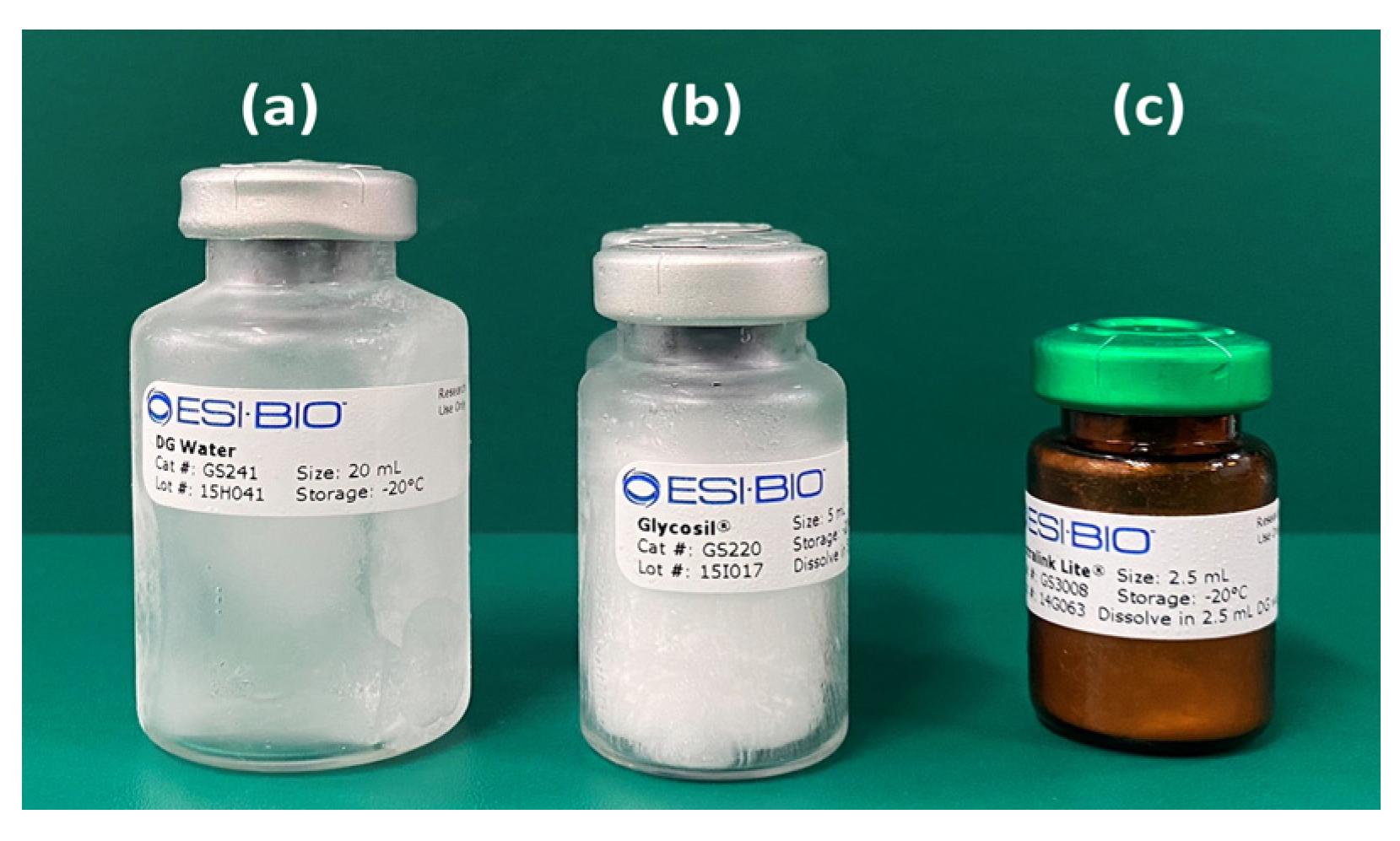
| HyA control | HYALURONSAN HA-SHY | Powder |
| tHyA | Glycosil® | Sponge body |
| ux-tHyA | Glycosil® + DG water | Sol |
| At this time, BMP, and nHAp were added to ux-tHyA | ||
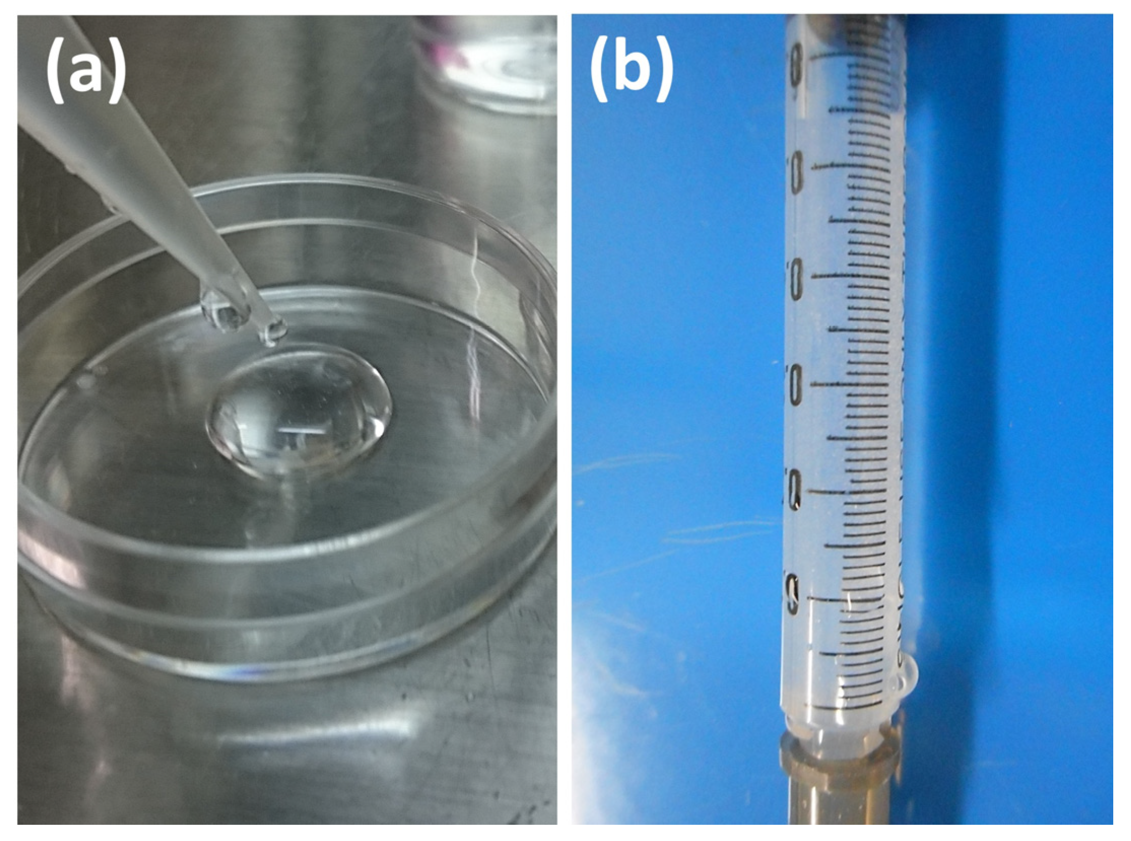
| x-tHyA | Glycosil® + DG water + Extralink Lite® | Sol (up to 20 min) Gel (after 20 min) |
| Dried HyA control | Freeze-dried (HyA control + water) | Sponge body |
| Dried ux-tHyA | Freeze-dried ux-tHyA | Sponge body |
| Dried x-tHyA | Freeze-dried x-tHyA | Sponge body |
| (a) | ||||
| Dried Samples | Material Characterization of HyA | |||
| FTIR | SEM | Hyaluronidase Dissolution Tests | TG/DSC | |
| HyA control | ● | ● | ● | ● |
| ux-tHyA | ● | ● | ● | ● |
| x-tHyA | ● | ● | ● | ● |
| (b) | ||||
| Samples | Characterization of the Use of nHAp | |||
| Observation of Protein Binding | Accelerated Protein Release Tests | |||
| nHAp*FITC-Collagen (±) | ● | |||
| x-tHyA SG*nHAp (±) | ● | |||
| (c) | ||||
| Samples | Animal Experiments | |||
| Direct Injection into Cranial Area | Set in a Teflon Ring and Placed on Cranial Bone | |||
| SG I*nHAp (±) | ● | |||
| SG II*BMP (±) | ● | |||
| Sample | Number of Ossification Confirmed | Number of Ossification Not Confirmed |
|---|---|---|
| Control SG I*nHAp (−) # (x-tHyA + BMP) | 0 | 10 |
| Test SG I*nHAp (+) # (x-tHyA + BMP + nHAp) | 7 | 3 |
Publisher’s Note: MDPI stays neutral with regard to jurisdictional claims in published maps and institutional affiliations. |
© 2022 by the authors. Licensee MDPI, Basel, Switzerland. This article is an open access article distributed under the terms and conditions of the Creative Commons Attribution (CC BY) license (https://creativecommons.org/licenses/by/4.0/).
Share and Cite
Hachinohe, Y.; Taira, M.; Hoshi, M.; Hatakeyama, W.; Sawada, T.; Kondo, H. Bone Formation on Murine Cranial Bone by Injectable Cross-Linked Hyaluronic Acid Containing Nano-Hydroxyapatite and Bone Morphogenetic Protein. Polymers 2022, 14, 5368. https://doi.org/10.3390/polym14245368
Hachinohe Y, Taira M, Hoshi M, Hatakeyama W, Sawada T, Kondo H. Bone Formation on Murine Cranial Bone by Injectable Cross-Linked Hyaluronic Acid Containing Nano-Hydroxyapatite and Bone Morphogenetic Protein. Polymers. 2022; 14(24):5368. https://doi.org/10.3390/polym14245368
Chicago/Turabian StyleHachinohe, Yuki, Masayuki Taira, Miki Hoshi, Wataru Hatakeyama, Tomofumi Sawada, and Hisatomo Kondo. 2022. "Bone Formation on Murine Cranial Bone by Injectable Cross-Linked Hyaluronic Acid Containing Nano-Hydroxyapatite and Bone Morphogenetic Protein" Polymers 14, no. 24: 5368. https://doi.org/10.3390/polym14245368