The Optimization of Process Parameters and Characterization of High-Performance CF/PEEK Composites Prepared by Flexible CF/PEEK Plain Weave Fabrics

 , , , and
Abstract
:
1. Introduction
2. Materials and Methods
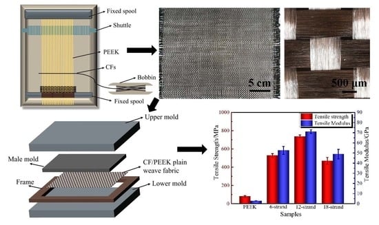
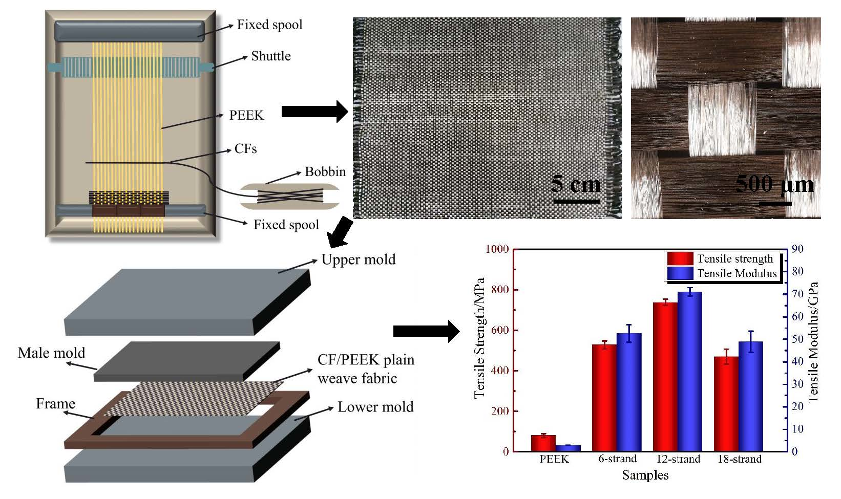
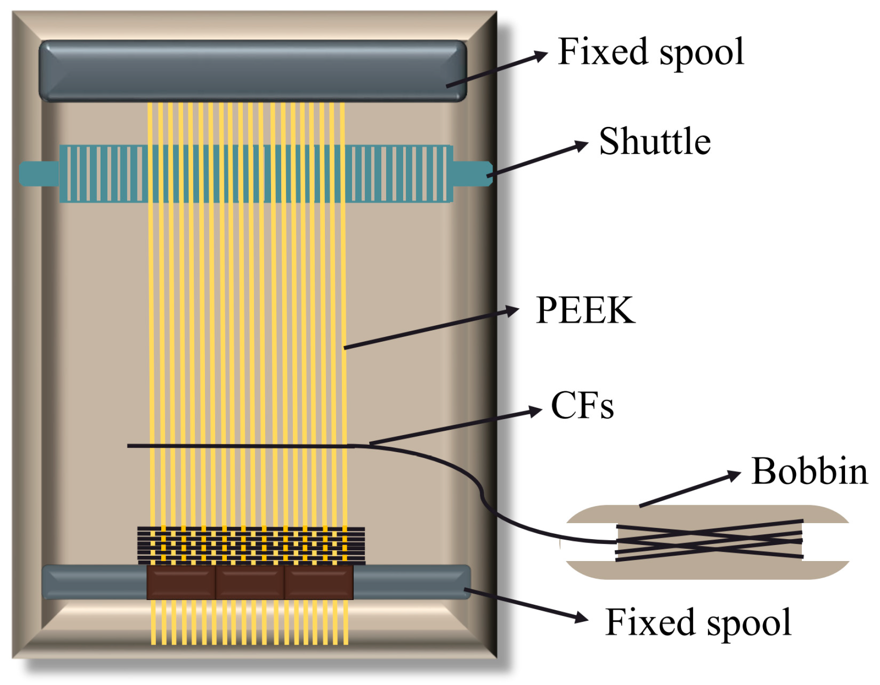
2.1. Materials
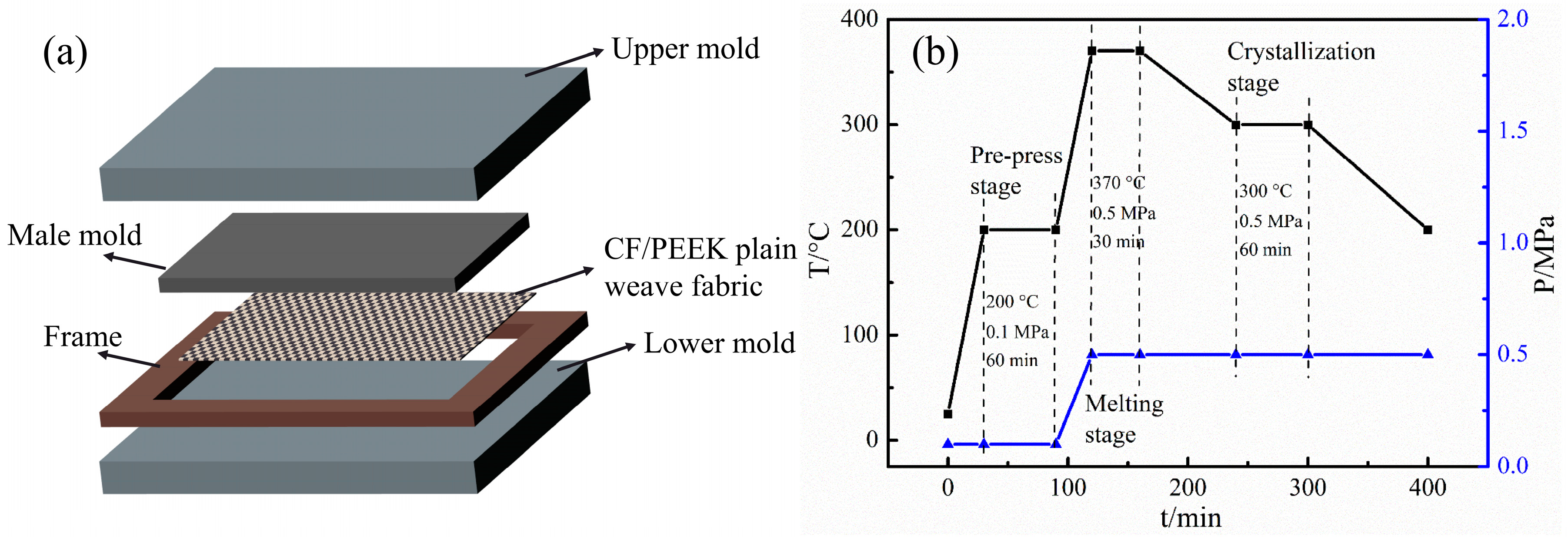
2.2. Hot Compaction
2.3. Characterization
2.3.1. Surface Morphology
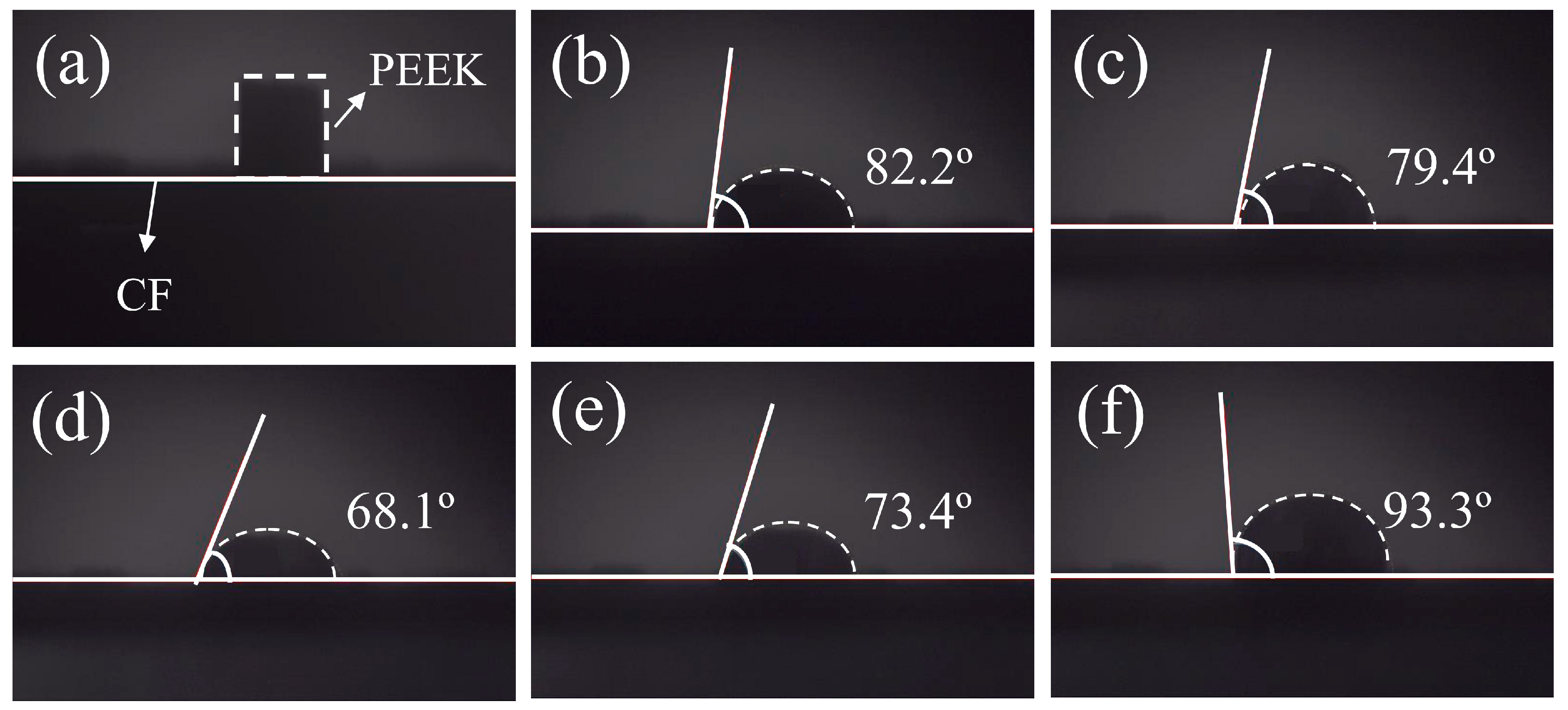
2.3.2. Contact Angle Measurement
2.3.3. Thermal Properties and Crystallinity
2.3.4. Resin Mass Contents
2.4. Mechanical Properties
2.4.1. Tensile Tests
- Pmax is the maximum force carried by test coupon before failure (N),
- b is the width of the beam (mm) and
- h is the thickness of the beam (mm)
- is the tensile modulus (GPa),
- is the tensile strength between two selected points (MPa),
- is the strain between the two selected points.
2.4.2. Bending Tests
- is the flexural strength (MPa),
- P is the applied force (N),
- L is the supported span (mm),
- b is the width of the beam (mm) and
- h is the thickness of the beam (mm).
3. Results and Discussion
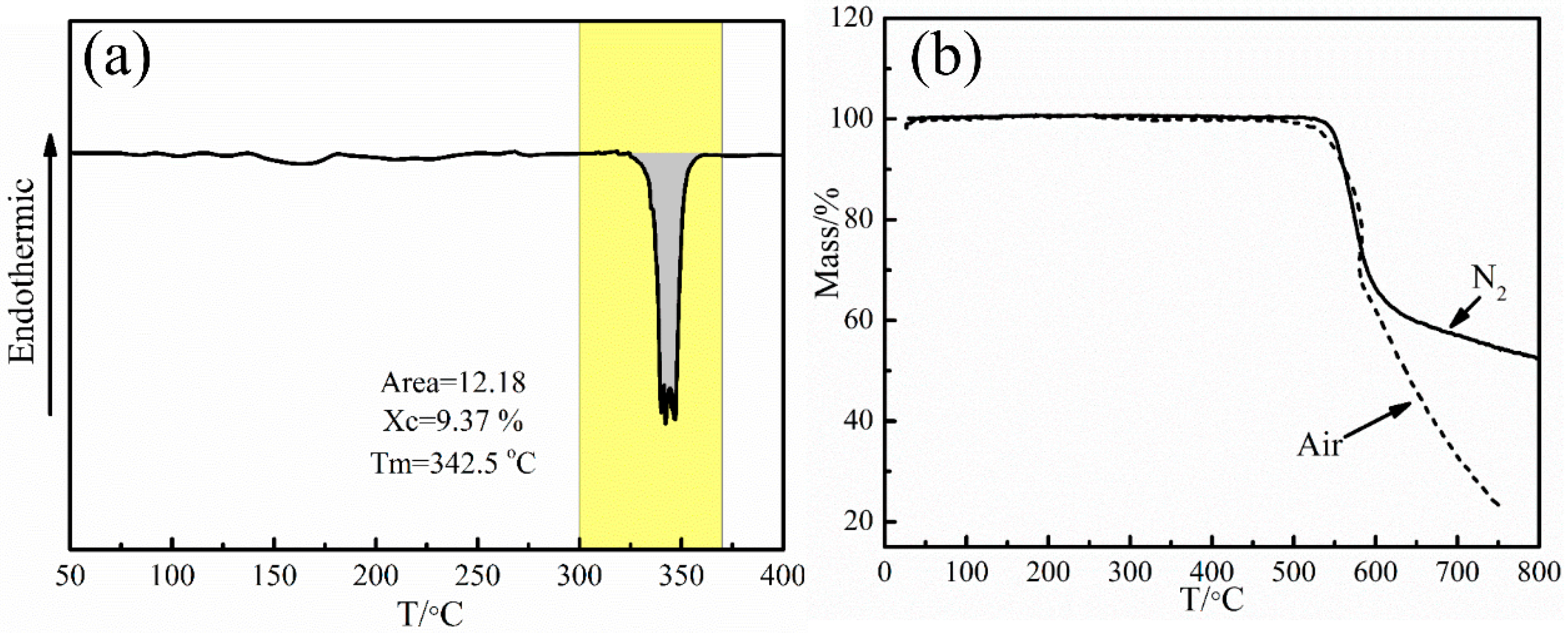
3.1. Determination of Molding Temperature
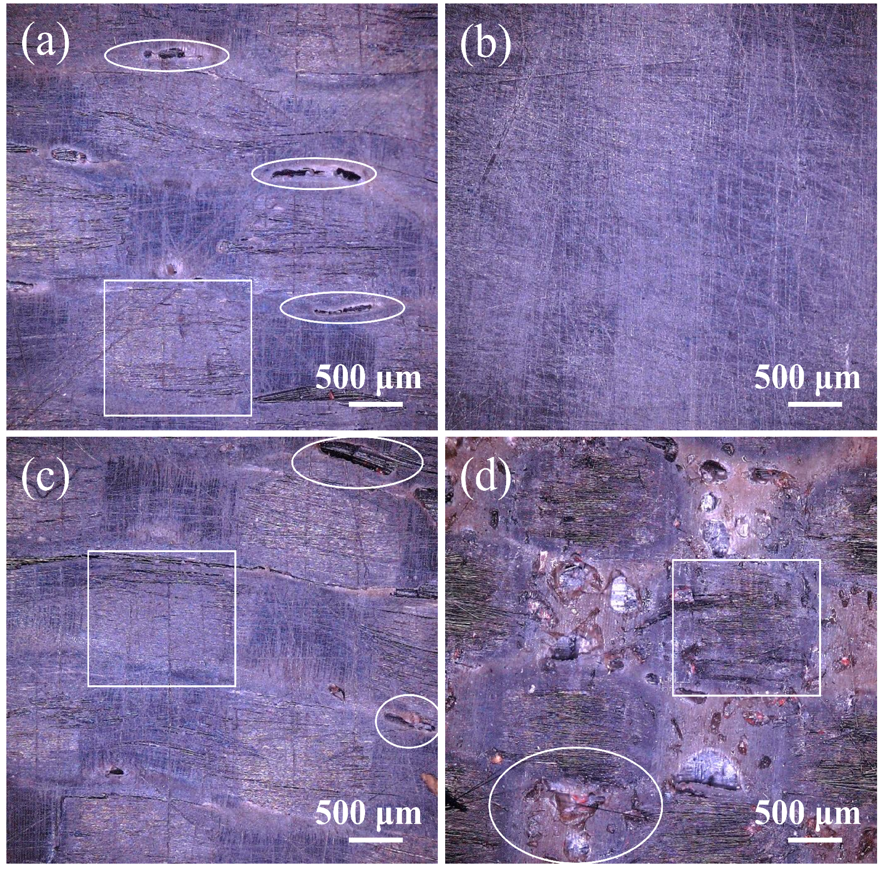
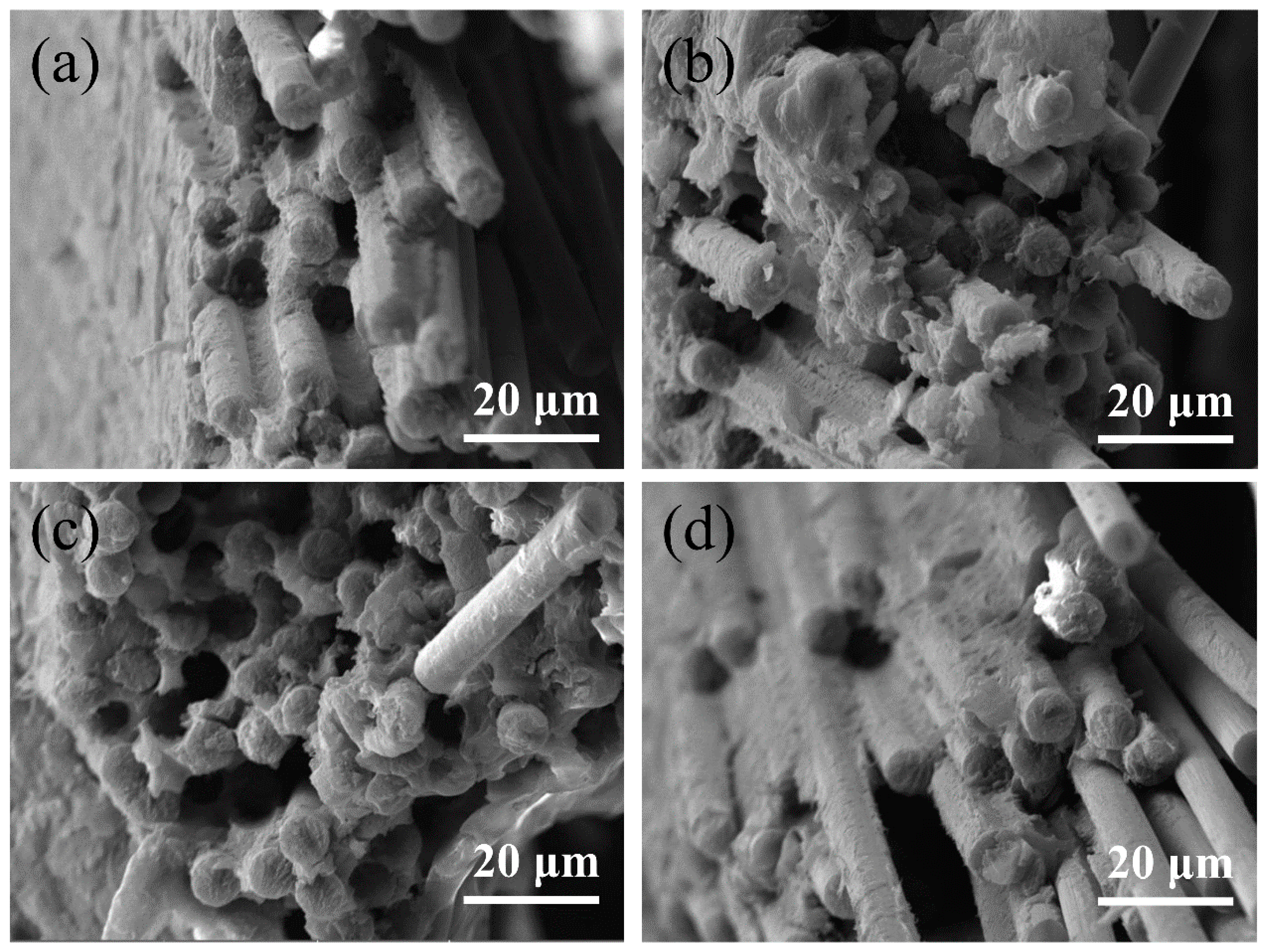
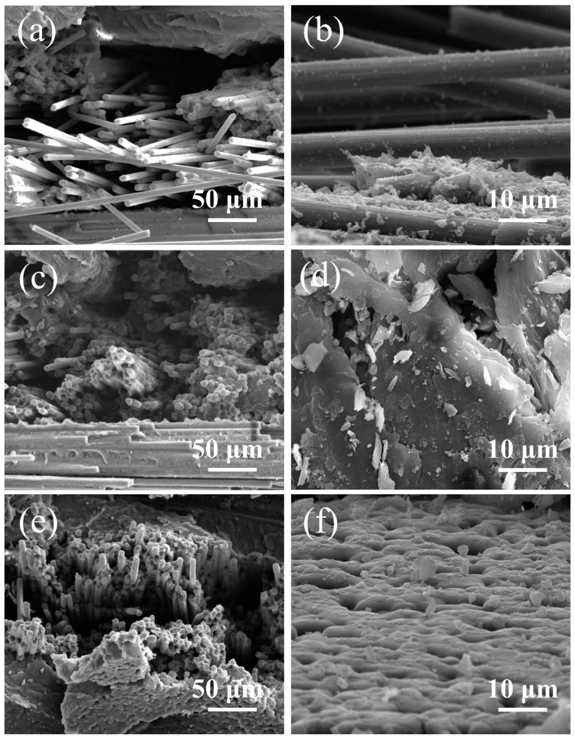
3.2. Effects of Molding Pressure
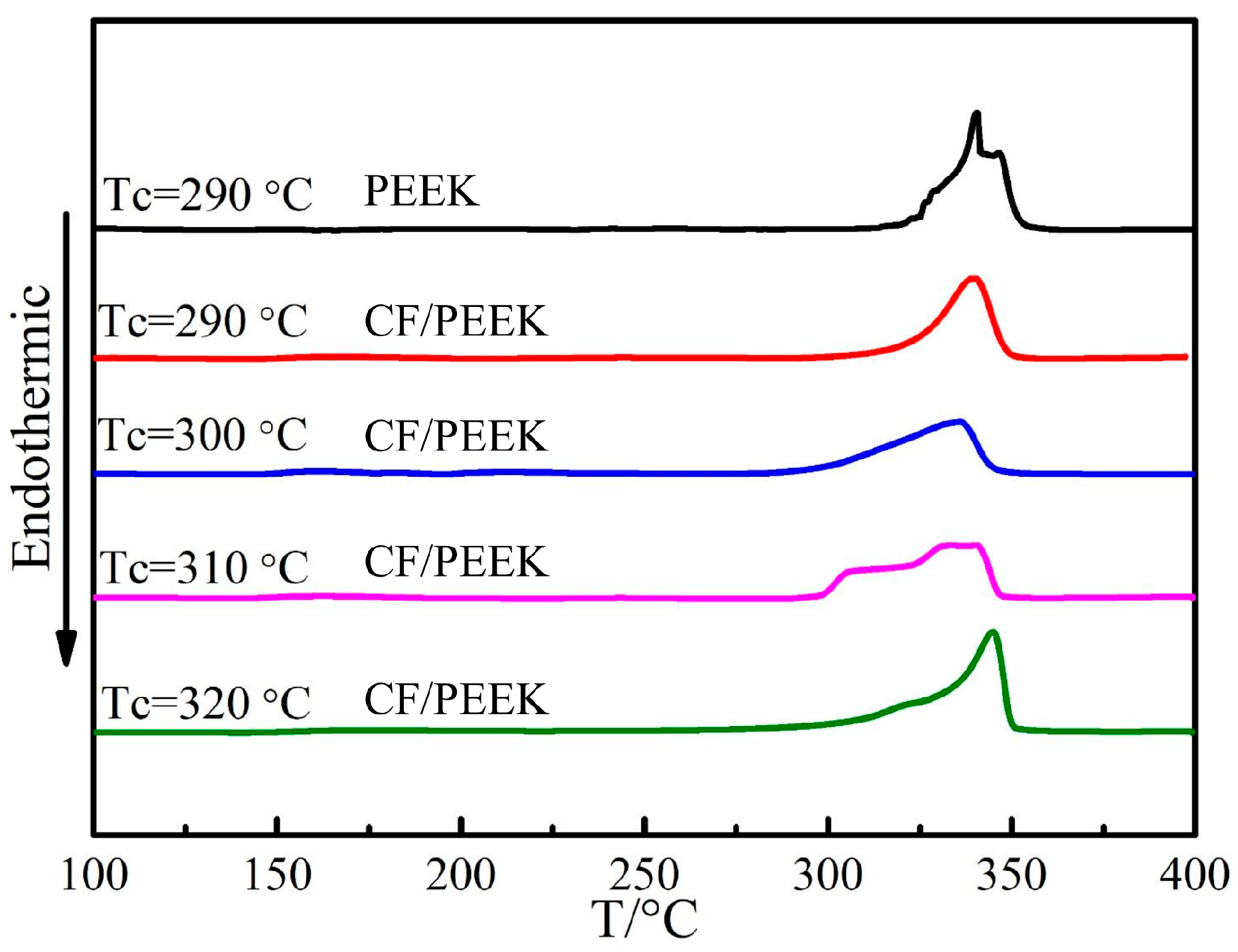
3.3. Selection of Crystallization Temperature
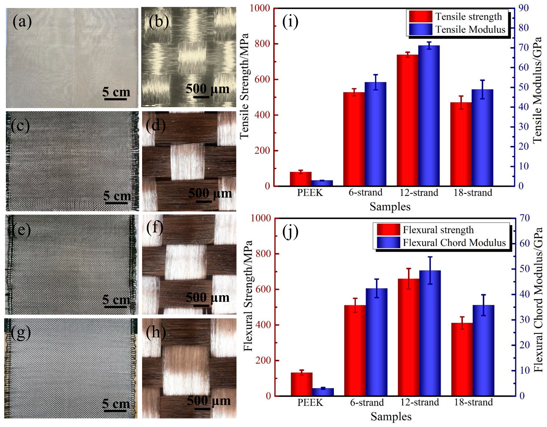
3.4. Effect of Resin Content
4. Conclusions
Author Contributions
Funding
Conflicts of Interest
References
- Saleem, A.; Frormann, L.; Iqbal, A. High performance thermoplastic composites: Study on the mechanical, thermal, and electrical resistivity properties of carbon fiber-reinforced polyetheretherketone and polyethersulphone. Polym. Compos. 2007, 12, 785–796. [Google Scholar] [CrossRef]
- Cogswell, F.N. Processing and application of thermoplastic structural composites. Makromol. Chem. Macromol. Symp 1991, 180, 165–180. [Google Scholar] [CrossRef]
- Sandler, J.; Windle, A.H.; Werner, P. Carbon-nanofibre-reinforced poly (ether ether ketone) fibre. J. Mater. Sci. 2003, 7, 2135–2141. [Google Scholar] [CrossRef]
- Offringa, A.R. Thermoplastic applications composites-rapid processing and applications. Compos. Part A 1996, 27A, 329–336. [Google Scholar] [CrossRef]
- Pan, L.; Yapici, U. A comparative study on mechanical properties of carbon fiber/PEEK composites. Adv. Compos. Mater. 2016, 25, 359–374. [Google Scholar] [CrossRef]
- Jang, J.; Hyuncheol, K. Improvement of carbon fiber/PEEK Hybrid fabric composites using plasma treatment. Polym. Compos. 2010, 18, 125–132. [Google Scholar] [CrossRef]
- Yang, I.Y.; Kim, Y.N.; Ra, S.W. The effects of temperature change on the bending strength of CF/PEEK laminates after impact. Key Eng. Mater. 2004, 270–273, 1917–1922. [Google Scholar] [CrossRef]
- Gao, S.L.; Kim, J.K. Correlation among crystalline morphology of PEEK, interface bond strength, and in-plane mechanical properties of carbon/PEEK composites. J. Appl. Polym. Sci. 2001, 4, 154–170. [Google Scholar] [CrossRef]
- Lee, Y.; Porter, R.S. Crystallization of peek in carbon fiber composites. Polym. Eng. Sci. 1986, 26, 633–639. [Google Scholar] [CrossRef]
- Vu-Khanh, T.; Hachimi, B.D. Crystallization mechanism in PEEK/carbon fiber composites. J. Thermoplast. Compos. Mater. 1997, 10, 488–501. [Google Scholar]
- Svensson, N.; Shishoo, R.; Gilchrist, M. Manufacturing of thermoplastic composites from commingled yarns—A review. J. Thermoplast. Compos. Mater. 1998, 11, 22–56. [Google Scholar] [CrossRef]
- Swolfs, Y.; Gorbatikh, L.; Verpoest, I. Fibre hybridisation in polymer composites: A review. Compos. Part A Appl. Sci. Manuf. 2014, 67, 181–200. [Google Scholar] [CrossRef] [Green Version]
- Hine, P.J.; Bonner, M.J.; Ward, I.M.; Swolfs, Y.; Verpoest, I. The influence of the hybridisation configuration on the mechanical properties of hybrid self reinforced polyamide 12/carbon fibre composites. Compos. Part A Appl. Sci. Manuf. 2017, 95, 141–151. [Google Scholar] [CrossRef] [Green Version]
- Mouritz, A.P.; Bannister, M.K.; Falzon, P.J.; Leong, K.H. Review of applications for advanced three-dimensional fibre textile composites. Compos. Part A Appl. Sci. Manuf. 1999, 30, 1445–1461. [Google Scholar] [CrossRef]
- Abounaim, M.; Diestel, O.; Offmann, G.; Cherif, C. High performance thermoplastic composite from flat knitted multi-layer textile preform using hybrid yarn. Compos. Sci. Technol. 2011, 71, 511–519. [Google Scholar] [CrossRef] [Green Version]
- Poe, C.C.; Dexter, H.B.; Raju, I.S. Review of the NASA textile composites research. J. Aircr. 1999, 36, 876–884. [Google Scholar] [CrossRef]
- Beehag, A.; Ye, L. Role of cooling pressure on interlaminar fracture properties of commingled CF/PEEK composites. Compos. Part A 1996, 8, 175–182. [Google Scholar] [CrossRef]
- Luo, H.; Xiong, G.; Yang, Z.; Raman, S.R.; Li, Q.; Ma, C.; Li, D.; Wang, Z.; Wan, Y. Preparation of three-dimensional braided carbon fiber-reinforced PEEK composites for potential load-bearing bone fixations. Part I. Mechanical properties and cytocompatibility. J. Mech. Behav. Biomed. Mater. 2014, 29, 103–113. [Google Scholar] [CrossRef]
- Bessard, E.; De Almeida, O.; Bernhart, G. Unified isothermal and non-isothermal modelling of neat PEEK crystallization. J. Therm. Anal. Calorim. 2014, 115, 1669–1678. [Google Scholar] [CrossRef]
- Tardif, X.; Pignon, B.; Boyard, N.; Schmelzer, J.W.P.; Sobotka, V.; Delaunay, D.; Schick, C. Experimental study of crystallization of PolyEtherEtherKetone (PEEK) over a large temperature range using a nano-calorimeter. Polym. Test. 2014, 36, 10–19. [Google Scholar] [CrossRef]
- Xiao, X.R.; Denault, J.; Vu-Khanh, T. The Effect of low melt temperature on morphology and Mode-I fracture toughness of PEEK/carbon composite. J. Thermoplast. Compos. Mater. 1992, 5, 64–75. [Google Scholar] [CrossRef]
- Velisaris, C.N.; Seferis, J.C. Crystallization kinetics of polyetheretherketone (peek) matrices. Polym. Eng. Sci. 1986, 26, 1574–1581. [Google Scholar] [CrossRef]
- Tierney, J.J.; Gillespie, J.W. Crystallization kinetics behavior of PEEK based composites exposed to high heating and cooling rates. Compos. Part A Appl. Sci. Manuf. 2004, 35, 547–558. [Google Scholar] [CrossRef]
- Gao, S.L.; Kim, J.K. Cooling rate influences in carbon fibre/PEEK composites. Part 1. Crystallinity and interface adhesion. Compos. Part A Appl. Sci. Manuf. 2000, 31, 517–530. [Google Scholar] [CrossRef]
- Mohmmed, R.; Zhang, F.; Sun, B.; Gu, B. Static and low-velocity impact on mechanical behaviors of foam sandwiched composites with different ply angles face sheets. J. Compos. Mater. 2014, 48, 1173–1188. [Google Scholar] [CrossRef]
- Manikandan, V.; Winowlin Jappes, J.T.; Suresh Kumar, S.M.; Amuthakkannan, P. Investigation of the effect of surface modifications on the mechanical properties of basalt fibre reinforced polymer composites. Compos. Part B Eng. 2012, 43, 812–818. [Google Scholar] [CrossRef]
- Tanniru, M.; Misra, R.D.K. On enhanced impact strength of calcium carbonate-reinforced high-density polyethylene composites. Mater. Sci. Eng. A 2005, 405, 178–193. [Google Scholar] [CrossRef]
- Deporter, J.K.; Baird, D.G.; Wilkes, G.L. The Effects of thermal history on the properties of semicrystalline thermoplastic composites: A Review of experimental and numerical investigations 1. J. Macromol. Sci. Part C 1993, 33, 1–79. [Google Scholar] [CrossRef]
- Zhang, Y.; Fuentes, C.A.; Koekoekx, R.; Clasen, C.; Van Vuure, A.W.; De Coninck, J.; Seveno, D. Spreading dynamics of molten polymer drops on glass substrates. Langmuir 2017, 33, 8447–8454. [Google Scholar] [CrossRef]
- Vera, J.; Contraires, E.; Brulez, A.C.; Larochette, M.; Valette, S.; Benayoun, S. Wetting of polymer melts on coated and uncoated steel surfaces. Appl. Surf. Sci. 2017, 410, 87–98. [Google Scholar] [CrossRef]
- Dasriaux, M.; Castagnet, S.; Thilly, L.; Chocinski-Arnault, L.; Boyer, S.A.E. Evolution of the amorphous fraction of PEEK during annealing at atmospheric and high pressure above the glass transition temperature. J. Appl. Polym. Sci. 2013, 130, 1148–1157. [Google Scholar] [CrossRef]
- Medellín-Rodríguez, F.J.; Phillips, P.J. Bulk crystallization of poly(aryl ether ether ketone) (PEEK). Polym. Eng. Sci. 1996, 36, 703–712. [Google Scholar] [CrossRef]
- Wang, W.; Qi, Z.; Jeronimidis, G. Studies on interface structure and crystal texture of poly(ether-ether-ketone)-carbon fibre composite. J. Mater. Sci. 1991, 26, 5915–5920. [Google Scholar] [CrossRef]
- Denault, J. Interfacial interaction in carbon fiber/thermoplastic composites. Compos. Interfaces 1994, 2, 275–289. [Google Scholar]


| Isothermal Temperature (°C) | Xt (MPa) | E1 (GPa) | Yt (MPa) | E2 (GPa) |
|---|---|---|---|---|
| 290 | 1301.54 ± 36.09 | 128.99 ± 9.73 | 47.63 ± 8.29 | 8.78 ± 1.70 |
| 300 | 1395.67 ± 95.84 | 132.32 ± 9.41 | 51.25 ± 10.01 | 8.86 ± 2.14 |
| 310 | 1380.91 ± 109.85 | 133.33 ± 11.24 | 46.94 ± 6.01 | 8.91 ± 1.03 |
| 320 | 1374.30 ± 91.27 | 135.83 ± 18.57 | 43.28 ± 5.67 | 8.88 ± 1.82 |
| T (°C) | Material | Resin Mass Content (%) | ΔHm (J/g) | Xc (%) |
|---|---|---|---|---|
| 290 | PEEK | 100 | 38.66 | 29.74 |
| 290 | CF/PEEK | 59.07 | 31.00 | 40.38 |
| 300 | CF/PEEK | 59.07 | 33.51 | 43.64 |
| 310 | CF/PEEK | 59.07 | 37.03 | 48.21 |
| 320 | CF/PEEK | 59.07 | 45.04 | 58.66 |
| Samples | Method | σt (MPa) | Et (GPa) | σf (MPa) | Ef (GPa) |
|---|---|---|---|---|---|
| CF/PEEK | 3D braided hybrid CF/PEEK fabric [18] | - | - | 456.2 ± 15.6 | 41.0 ± 3.5 |
| CF/PEEK | Commingled CF/PEEK unifabric [17] | - | - | 125.0 ± 25.0 (transverse) | 10.0 ± 0.9 (transverse) |
| CF/PEEK | PEEK powder [5] | - | - | 160 | - |
| CF/PEEK | Cowoven hybrid fabrics [6] | - | - | 700 | - |
| CF/PEEK | PEEK films [9] | 111 (transverse) | 3.9 (transverse) | - | - |
© 2018 by the authors. Licensee MDPI, Basel, Switzerland. This article is an open access article distributed under the terms and conditions of the Creative Commons Attribution (CC BY) license (http://creativecommons.org/licenses/by/4.0/).
Share and Cite
Lu, C.; Xu, N.; Zheng, T.; Zhang, X.; Lv, H.; Lu, X.; Xiao, L.; Zhang, D. The Optimization of Process Parameters and Characterization of High-Performance CF/PEEK Composites Prepared by Flexible CF/PEEK Plain Weave Fabrics. Polymers 2019, 11, 53. https://doi.org/10.3390/polym11010053
Lu C, Xu N, Zheng T, Zhang X, Lv H, Lu X, Xiao L, Zhang D. The Optimization of Process Parameters and Characterization of High-Performance CF/PEEK Composites Prepared by Flexible CF/PEEK Plain Weave Fabrics. Polymers. 2019; 11(1):53. https://doi.org/10.3390/polym11010053
Chicago/Turabian StyleLu, Chunrui, Nuo Xu, Ting Zheng, Xin Zhang, Hanxiong Lv, Xue Lu, Lin Xiao, and Dongxing Zhang. 2019. "The Optimization of Process Parameters and Characterization of High-Performance CF/PEEK Composites Prepared by Flexible CF/PEEK Plain Weave Fabrics" Polymers 11, no. 1: 53. https://doi.org/10.3390/polym11010053