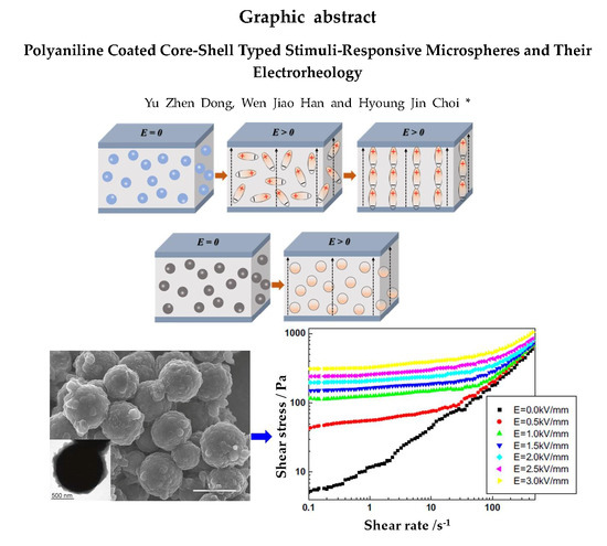
Polyaniline Coated Core-Shell Typed Stimuli-Responsive Microspheres and Their Electrorheology


Abstract
:
1. Introduction
2. Core-Shell Typed Microspheres
3. Electrorheology
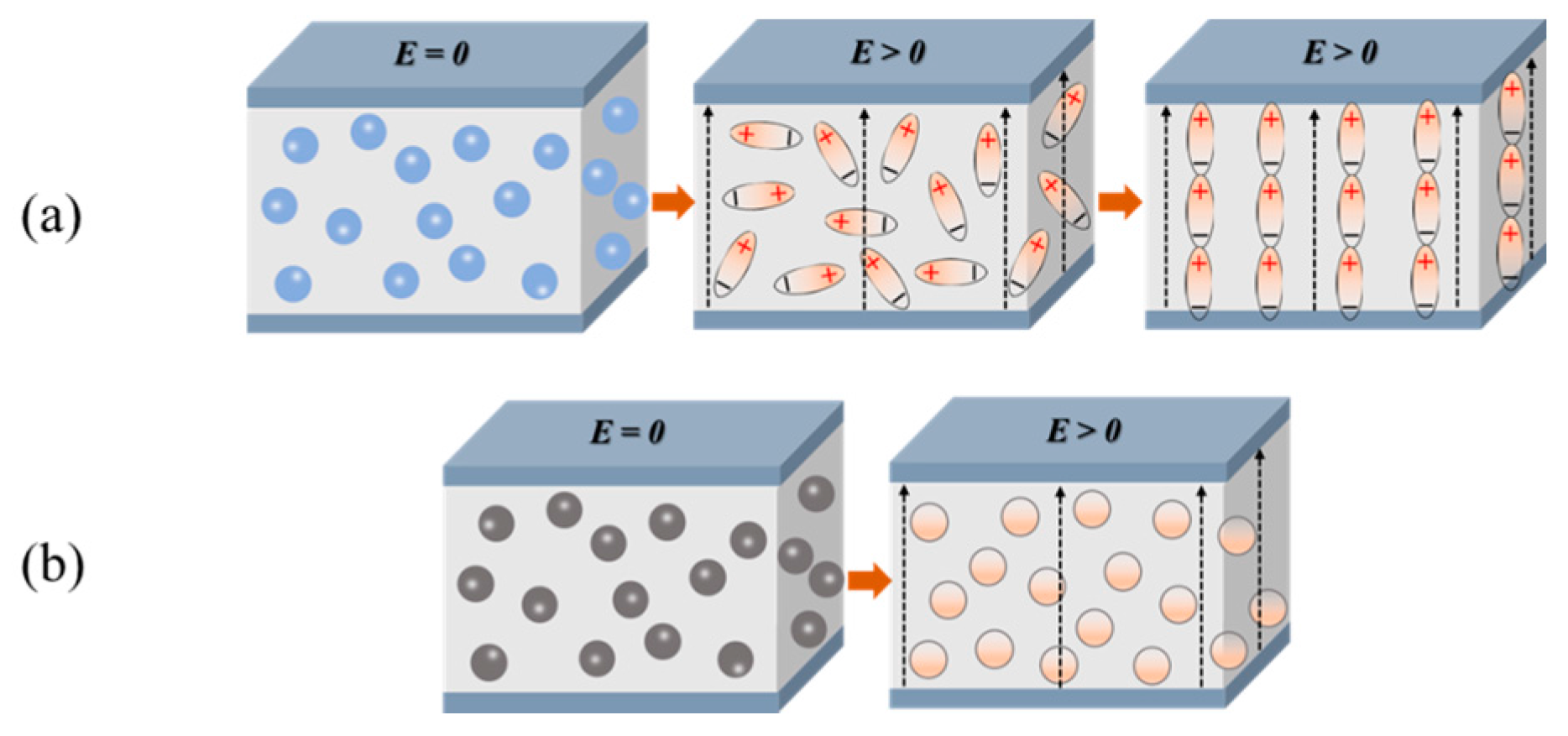
3.1. Electrorheological Phenomenon
3.2. Electrorheological Particles
4. Polyaniline-Coated Core-Shell Structured Microspheres
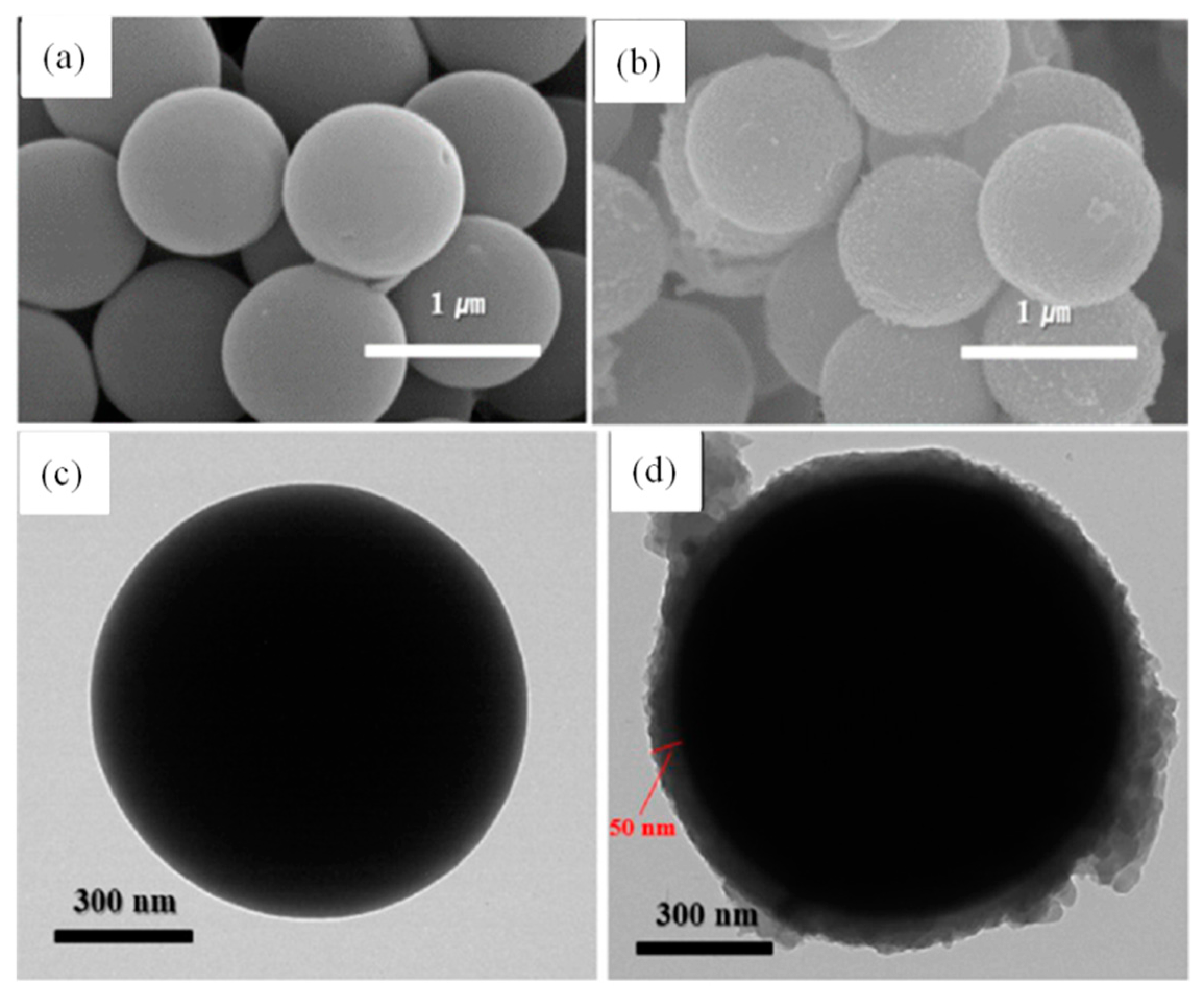
4.1. Inorganic Core
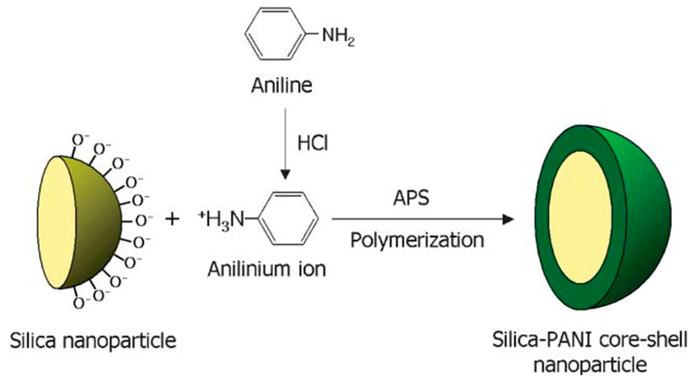
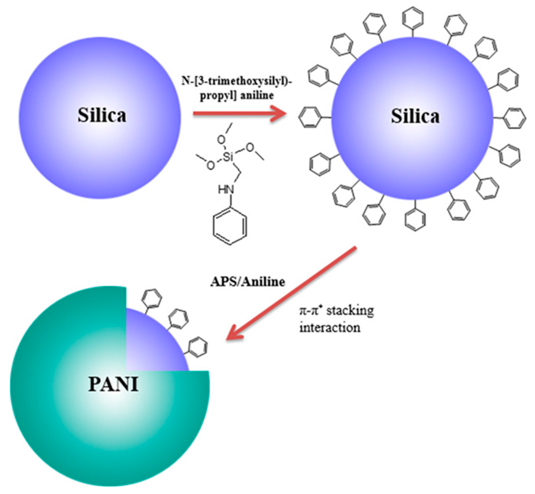
4.1.1. Silica (SiO2)
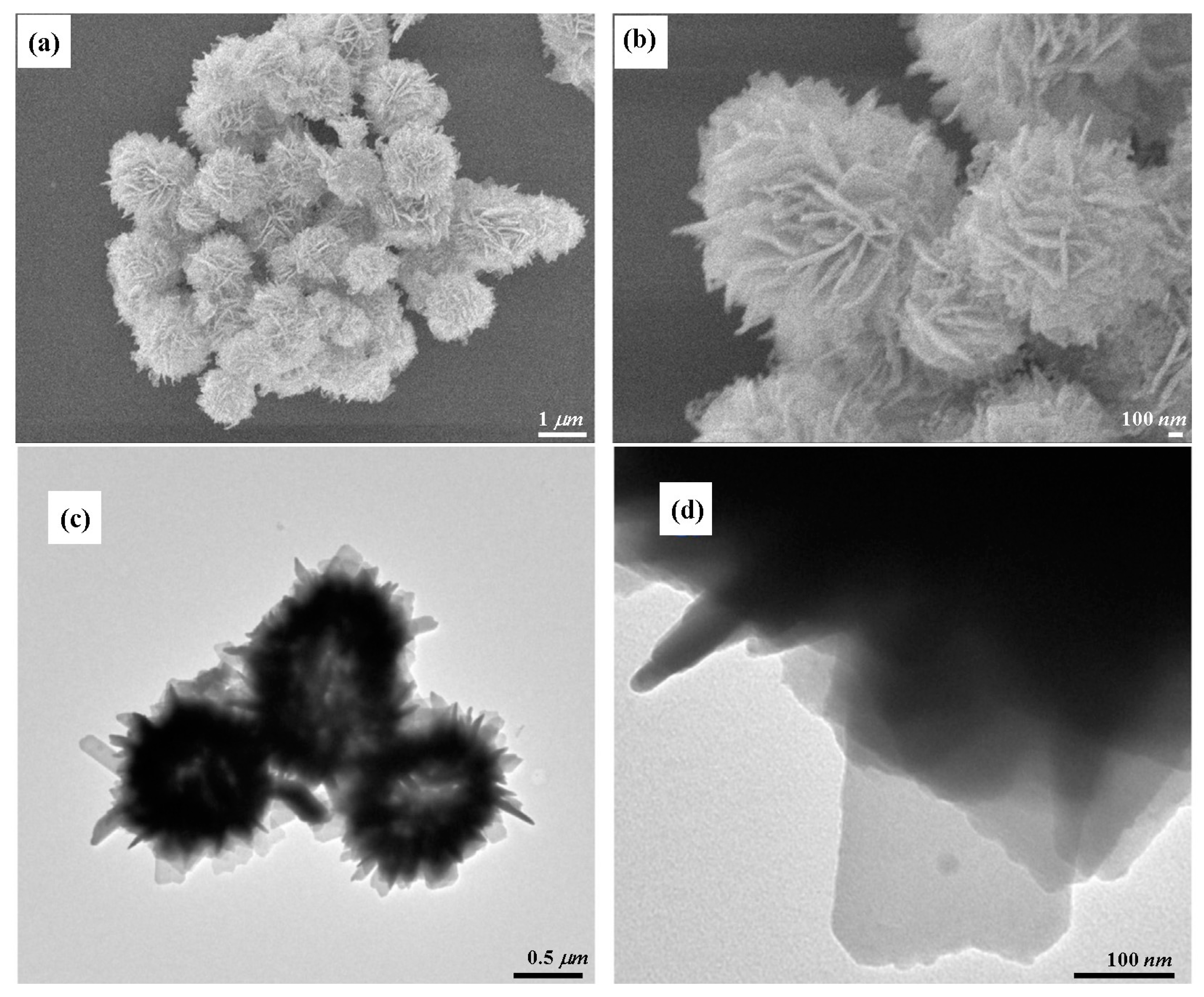
4.1.2. Ferric Oxide (Fe2O3)
4.1.3. Iron Oxide (Fe3O4)
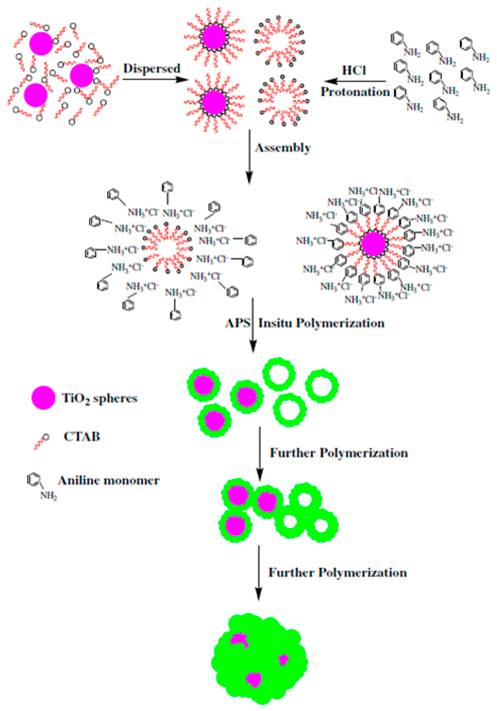
4.1.4. Titanium Oxide (TiO2)
4.2. Polymeric Core
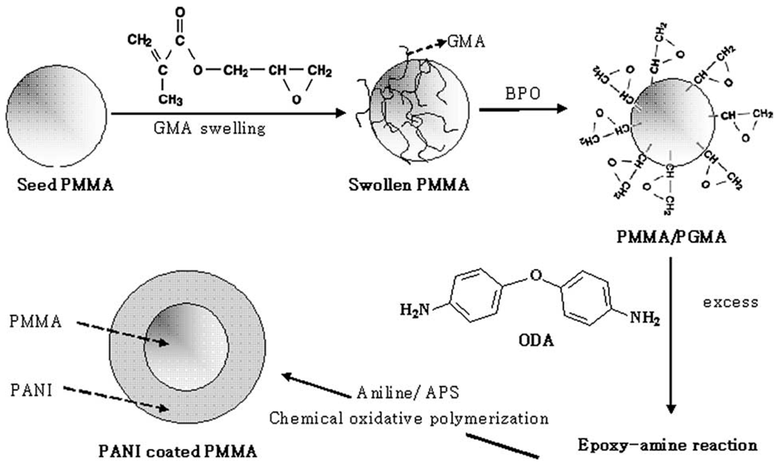
4.2.1. Poly(methyl methacrylate)
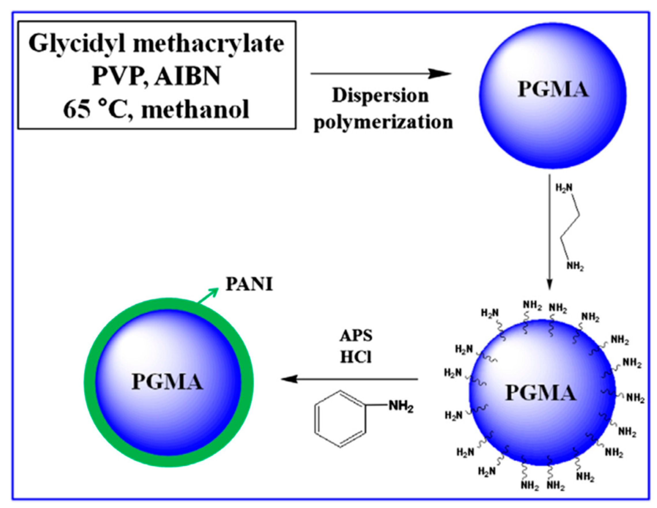
4.2.2. Poly(glycidyl methacrylate)
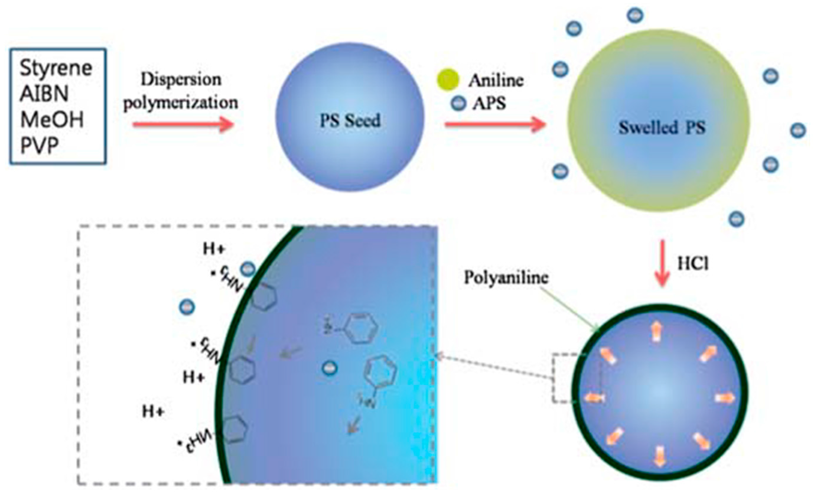
4.2.3. Polystyrene
5. Electrorheological Characteristics
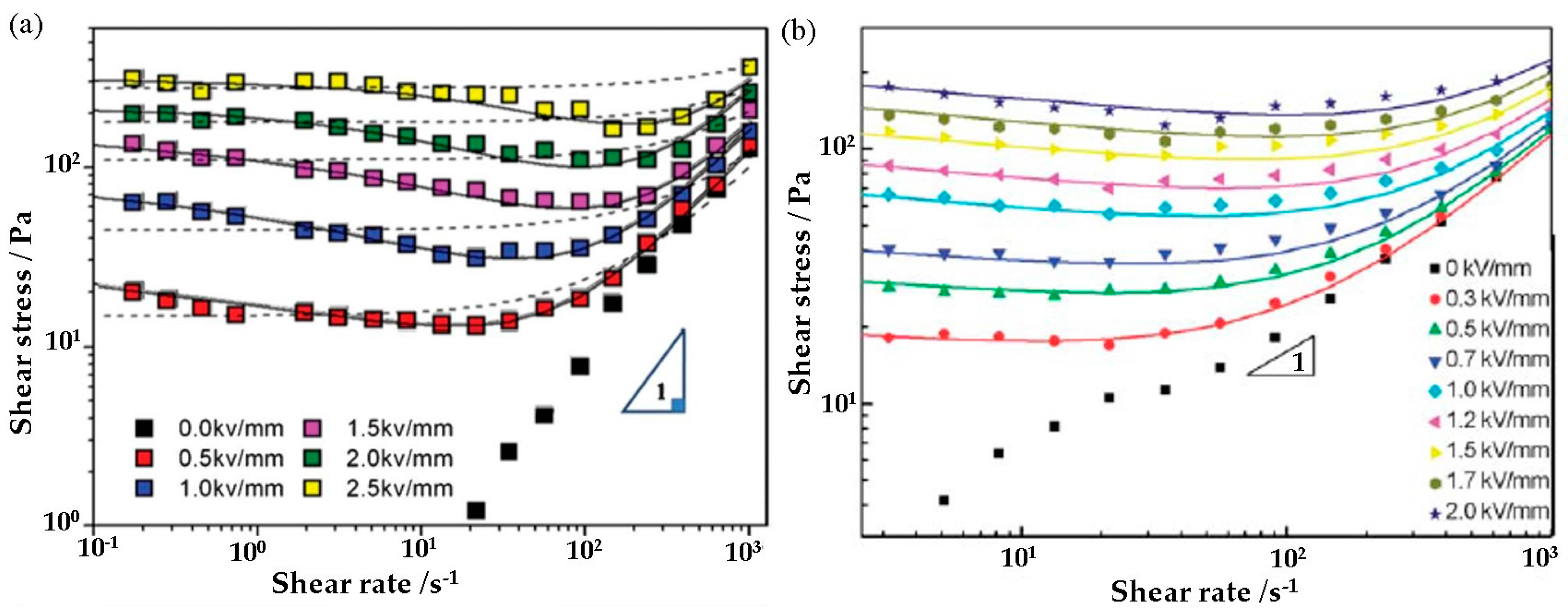
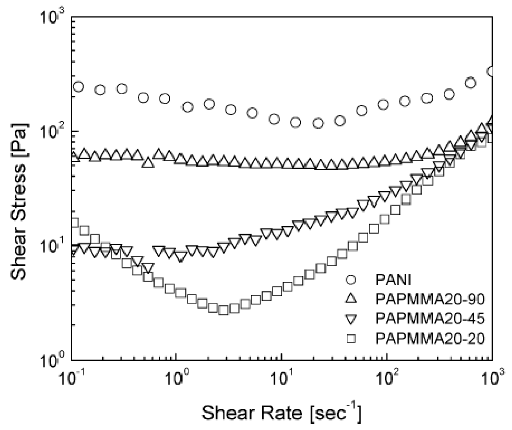
5.1. Shear Stress
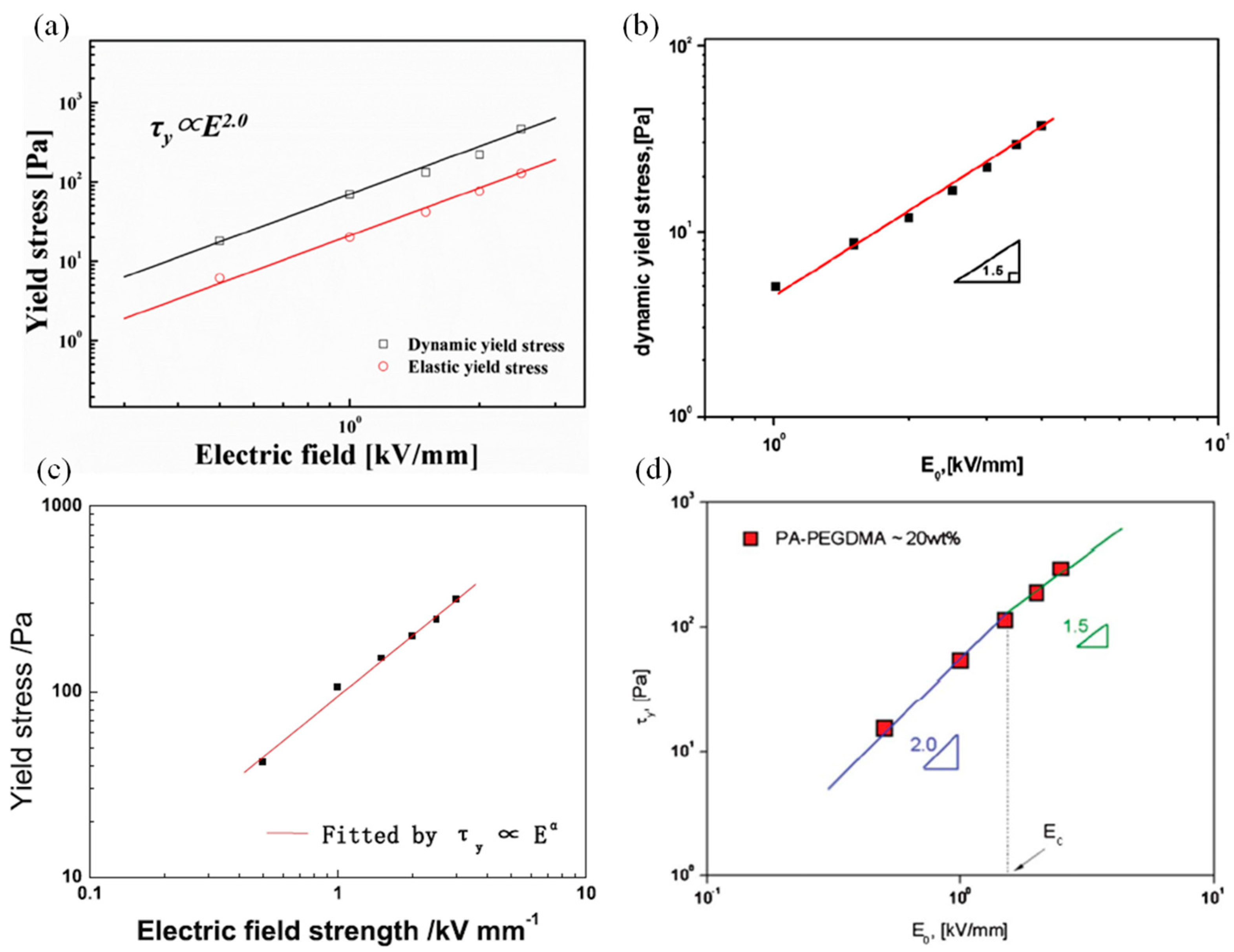
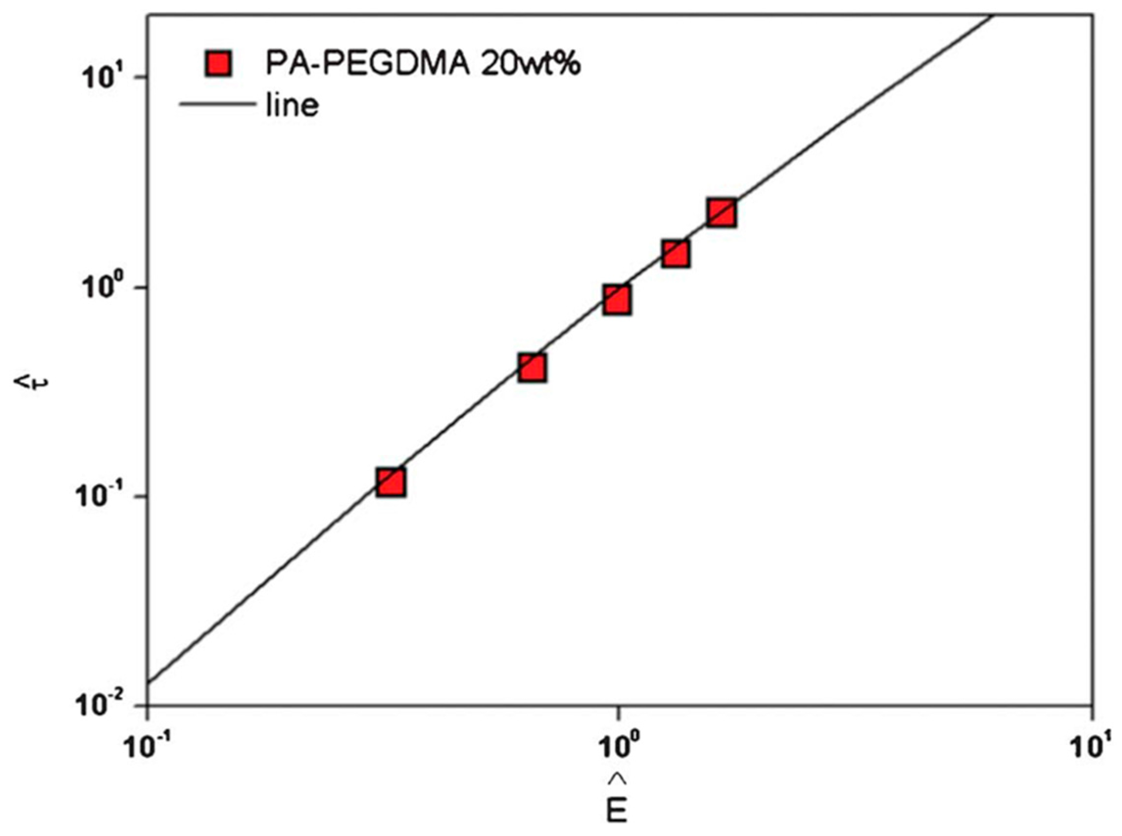
5.2. Yield Stress ()
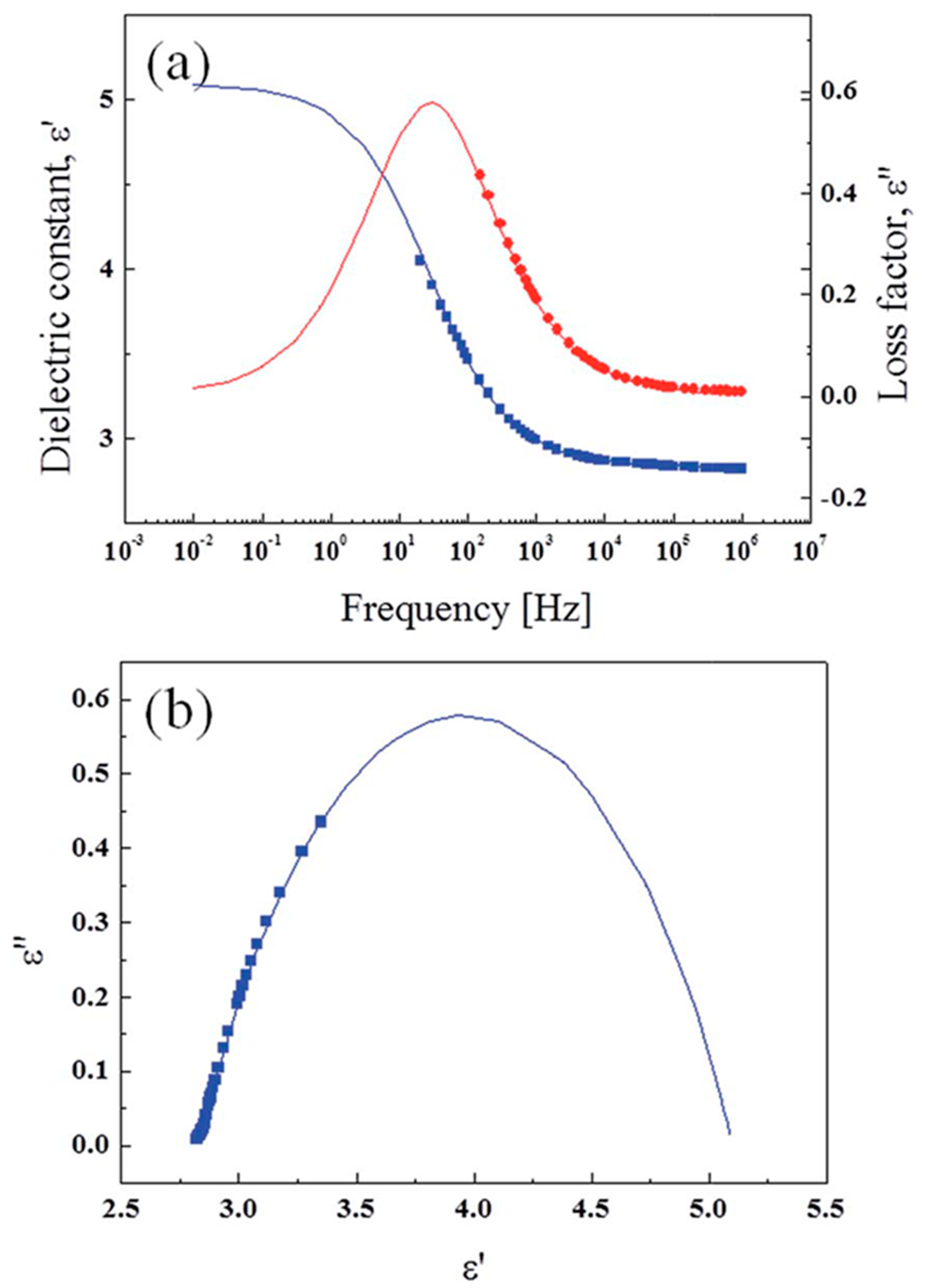
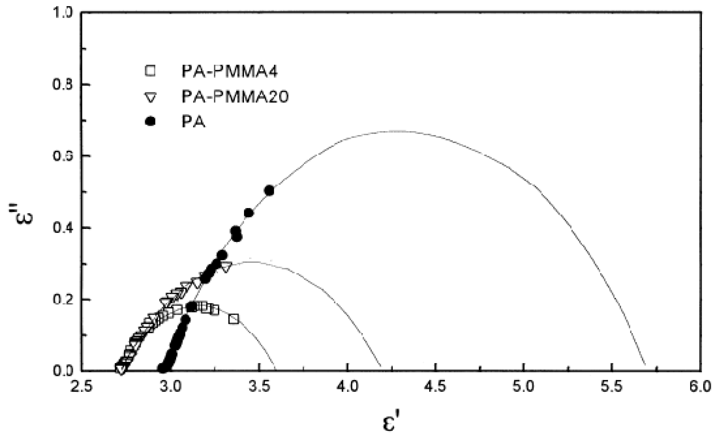
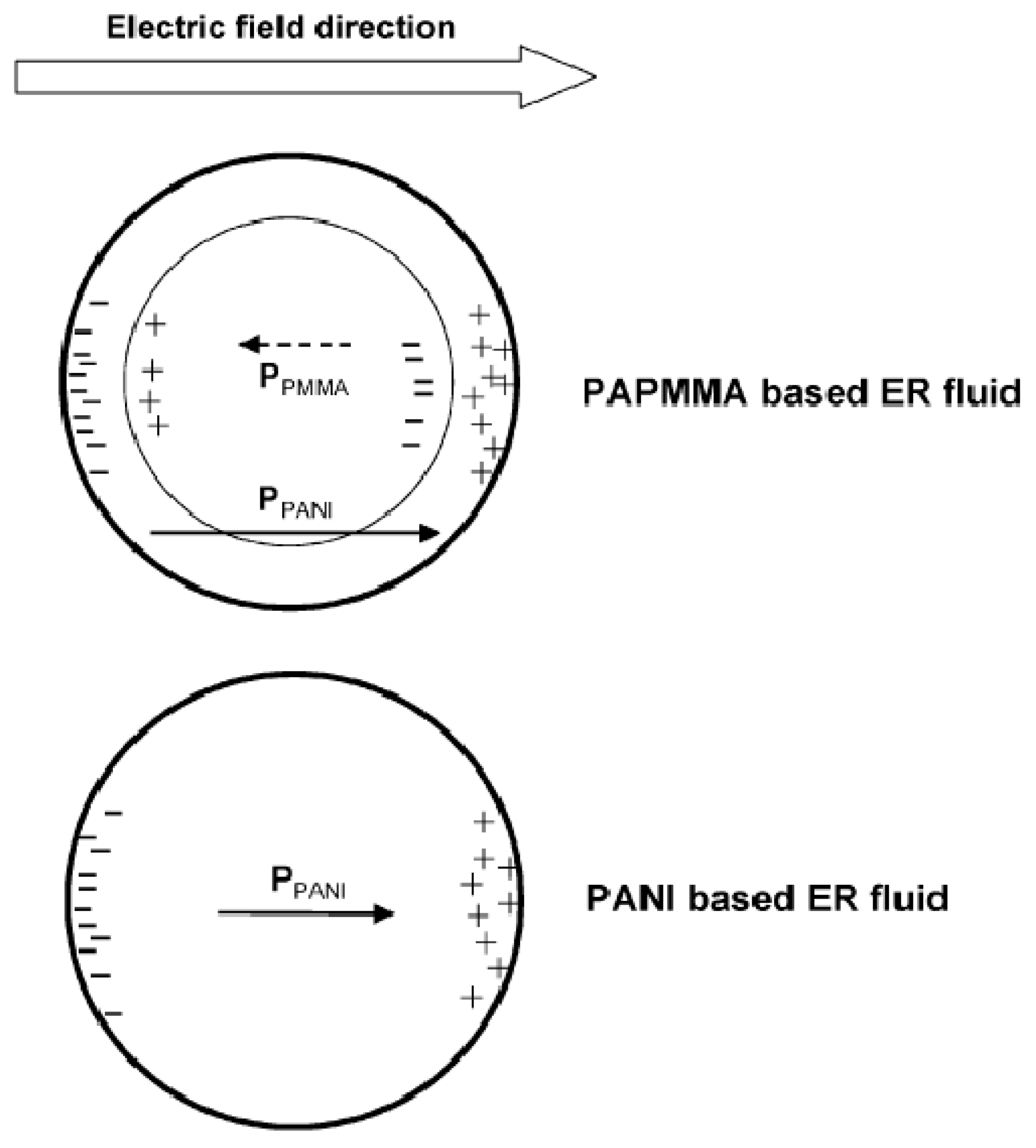
6. Dielectric Analysis
7. Conclusions
Acknowledgments
Conflicts of Interest
References
- Marins, J.A.; Soares, B.G. Ionic liquid-based organically modified silica for the development of new electrorheological fluids. Colloids Surf. A Physicochem. Eng. Asp. 2017, 529, 311–319. [Google Scholar] [CrossRef]
- Cabuk, M. Electrorheological response of mesoporous expanded perlite particles. Mesoporous Mesoporous Mater. 2017, 247, 60–65. [Google Scholar] [CrossRef]
- Do, T.G.; Lee, H.J.; Ko, Y.G.; Chun, Y.S.; Choi, U.S.; Kim, C.H. Influence of amine- and sulfonate-functional groups on electrorheological behavior of polyacrylonitrile dispersed suspension. Colloids Surf. A Physicochem. Eng. Asp. 2017, 514, 56–62. [Google Scholar] [CrossRef]
- Zhang, Z.L.; Zhang, Z.G.; Hao, B.N.; Zhang, H.Y.; Wang, M.; Liu, Y.D. Fabrication of imidazolium-based poly(ionic liquid) microspheres and their electrorheological responses. J. Mater. Sci. 2017, 52, 5778–5787. [Google Scholar] [CrossRef]
- Kamelreiter, M.; Kemmetmüller, W.; Kugi, A. Digitally controlled electrorheological valves and their application in vehicle dampers. Mechatronics 2012, 22, 629–638. [Google Scholar] [CrossRef]
- Jose, R.R.; Elia, R.; Tien, L.W.; Kaplan, D.L. Electroresponsive aqueous silk protein as “smart” mechanical damping fluid. ACS Appl. Mater. Interface 2014, 6, 6212–6216. [Google Scholar] [CrossRef] [PubMed]
- Tan, K.P.; Stanway, R.; Bullough, W.A. Dynamic velocity response of an electro-rheological (ER) clutch for robotic applications. Mech. Adv. Mater. Struct. 2006, 13, 1–12. [Google Scholar] [CrossRef]
- Choi, S.B.; Yook, J.Y.; Choi, M.K.; Nguyen, Q.H.; Lee, Y.S.; Han, M.S. Speed control of DC motor using electrorheological brake system. J. Intell. Mater. Syst. Struct. 2007, 18, 1191–1196. [Google Scholar] [CrossRef]
- Furusho, J.; Sakaguchi, M.; Takesue, N.; Koyanagi, K. Development of ER brake and its application to passive force display. J. Intell. Mater. Syst. Struct. 2002, 13, 425–429. [Google Scholar] [CrossRef]
- Su, J.S.; Cheng, H.B.; Wen, Y.F.; Feng, Y.P.; Tam, H.Y. Investigation into the mechanism for ultra smooth electrorheological finishing using wheel-like finishing tool. J. Mater. Process. Technol. 2016, 238, 124–131. [Google Scholar] [CrossRef]
- Pandey, A.K.; Pandey, P.C.; Agrawal, N.R.; Das, I. Synthesis and characterization of dendritic polypyrrole silver nanocomposite and its application as a new urea biosensor. J. Appl. Polym. Sci. 2018, 135, 45705. [Google Scholar] [CrossRef]
- Sriwichai, S.; Janmanee, R.; Phanichphant, S.; Shinbo, K.; Kato, K.; Kaneko, F.; Yamamoto, T.; Baba, A. Development of an electrochemical-surface plasmon dual biosensor based on carboxylated conducting polymer thin films. J. Appl. Polym. Sci. 2018, 135, 45641. [Google Scholar] [CrossRef]
- Jo, W.G.; Khan, M.; Tan, L.S.; Jeong, H.S.; Lee, S.H.; Park, S.Y. Polypyrrole nanocomposite with water-dispersible graphene. Macromol. Res. 2017, 25, 335–343. [Google Scholar] [CrossRef]
- Zhang, J.; Zeng, B.Z.; Zhao, F.Q. Fabrication of bi-monomer copolymer of pyrrole-indole for highly efficient solid phase microextraction of benzene derivatives. Talanta 2018, 176, 450–455. [Google Scholar] [CrossRef] [PubMed]
- Suganya, N.; Jaisankar, V.; Sivakumar, E.K.T. Conducting polymeric hydrogel electrolyte based on carboxymethylcellulose and polyacrylamide/polyaniline for supercapacitor applications. Int. J. Nanosci. 2017, 17, 1760003. [Google Scholar] [CrossRef]
- Zhang, L.F.; Wang, W.J.; Cheng, J.; Shi, Y.H.; Zhang, Q.; Dou, P.; Xu, X.H. Skeleton networks of graphene wrapped double-layered polypyrrole/polyaniline nanotubes for supercapacitor applications. J. Mater. Sci. 2018, 53, 787–798. [Google Scholar] [CrossRef]
- Ji, T.; Tu, R.; Mu, L.W.; Lu, X.H.; Zhu, J.H. Structurally tuning microwave absorption of core/shell structured cnt/polyaniline catalysts for energy efficient saccharide-hmf conversion. Appl. Catal. B Environ. 2018, 220, 581–588. [Google Scholar] [CrossRef]
- Sampreeth, T.; Al-Maghrabi, M.A.; Bahuleyan, B.K.; Ramesan, M.T. Synthesis, characterization, thermal properties, conductivity and sensor application study of polyaniline/cerium-doped titanium dioxide nanocomposites. J. Mater. Sci. 2018, 53, 591–603. [Google Scholar] [CrossRef]
- Gercek, B.; Yavuz, M.; Yilmaz, H.; Sari, B.; Unal, H.I. Comparison of electrorheological properties of some polyaniline derivatives. Colloids Surf. A Physicochem. Eng. Asp. 2007, 299, 124–132. [Google Scholar] [CrossRef]
- Yilmaz, H.; Zengin, H.; Unal, H.I. Synthesis and electrorheological properties of polyaniline/silicon dioxide composite. J. Mater. Sci. 2012, 47, 5276–5286. [Google Scholar] [CrossRef]
- Stenicka, M.; Pavlinek, V.; Saha, P.; Blinova, N.V.; Stejskal, J.; Quadrat, O. Conductivity of flowing polyaniline suspensions in electric field. Colloid Polym. Sci. 2008, 286, 1403–1409. [Google Scholar] [CrossRef]
- Cheng, Q.; Pavlinek, V.; He, Y.; Li, C.; Saha, P. Electrorheological characteristics of polyaniline/titanate composite nanotube suspensions. Colloid Polym. Sci. 2009, 287, 435–441. [Google Scholar] [CrossRef]
- Jang, W.H.; Kim, J.W.; Choi, H.J.; Jhon, M.S. Synthesis and electrorheology of camphorsulfonic acid doped polyaniline suspensions. Colloid Polym. Sci. 2001, 279, 823–827. [Google Scholar] [CrossRef]
- Kim, M.J.; Liu, Y.D.; Choi, H.J. Urchin-like polyaniline microspheres fabricated from self-assembly of polyaniline nanowires and their electro-responsive characteristics. Chem. Eng. J. 2014, 235, 186–190. [Google Scholar] [CrossRef]
- Gow, C.J.; Zukoski, C.F. The electrorheological properties of polyaniline suspensions. J. Colloid Interface Sci. 1990, 136, 175–188. [Google Scholar] [CrossRef]
- Jun, C.S.; Sim, B.M.; Choi, H.J. Fabrication of electric-stimuli responsive polyaniline/laponite composite and its viscoelastic and dielectric characteristics. Colloids Surf. A Physicochem. Eng. Asp. 2015, 482, 670–677. [Google Scholar] [CrossRef]
- Han, W.J.; Piao, S.H.; Choi, H.J. Synthesis and electrorheological characteristics of polyaniline@attapulgite nanoparticles via pickering emulsion polymerization. Mater. Lett. 2017, 204, 42–44. [Google Scholar] [CrossRef]
- Marins, J.A.; Giulieri, F.; Soares, B.G.; Bossis, G. Hybrid polyaniline-coated sepiolite nanofibers for electrorheological fluid applications. Synth. Met. 2013, 185–186, 9–16. [Google Scholar] [CrossRef]
- Zheng, C.; Dong, Y.Z.; Liu, Y.; Zhao, X.P.; Yin, J.B. Enhanced stimuli-responsive electrorheological property of poly(ionic liquid)s-capsulated polyaniline particles. Polymers 2017, 9, 385. [Google Scholar] [CrossRef]
- Lim, G.H.; Choi, H.J. Fabrication of self-assembled polyaniline tubes and their electrorheological characteristics. Colloids Surf. A Physicochem. Eng. Asp. 2017, 530, 227–234. [Google Scholar] [CrossRef]
- Fang, Y.; Tan, J.; Lan, T.; Foo, S.G.F.; Pyun, D.G.; Lim, S.; Kim, D.H. Universal one-pot, one-step synthesis of core–shell nanocomposites with self-assembled tannic acid shell and their antibacterial and catalytic activities. J. Appl. Polym. Sci. 2018, 135, 45829. [Google Scholar] [CrossRef]
- Zhou, T.; Zhang, T.; Zeng, Y.; Zhang, R.; Lou, Z.; Deng, J.; Wang, L. Structure-driven efficient NiFe2O4 materials for ultra-fast response electronic sensing platform. Sens. Actuators B Chem. 2018, 255, 1436–1444. [Google Scholar] [CrossRef]
- Liu, Y.; Hou, W.J.; Sun, H.; Cui, C.; Zhang, L.Q.; Jiang, Y.; Wu, Y.X.; Wang, Y.Y.; Li, J.; Sumerlin, B.S.; et al. Thiol-ene click chemistry: A biocompatible way for orthogonal bioconjugation of colloidal nanoparticles. Chem. Sci. 2017, 8, 6182–6187. [Google Scholar] [CrossRef] [PubMed]
- Su, Y.; Guo, H.; Wang, Z.; Long, Y.; Li, W.; Tu, Y. Au@Cu2O core-shell structure for high sensitive non-enzymatic glucose sensor. Sens. Actuators B Chem. 2018, 255, 2510–2519. [Google Scholar] [CrossRef]
- Zhao, H.; Zhang, T.; Qi, R.; Dai, J.; Liu, S.; Fei, T.; Lu, G. Development of solution processible organic-inorganic hybrid materials with core-shell framework for humidity monitoring. Sens. Actuators B Chem. 2018, 255, 2878–2885. [Google Scholar] [CrossRef]
- Zhen, W.; Ning, X.; Yang, B.; Wu, Y.; Li, Z.; Lu, G. The enhancement of cds photocatalytic activity for water splitting via anti-photocorrosion by coating Ni2P shell and removing nascent formed oxygen with artificial gill. Appl. Catal. B Environ. 2018, 221, 243–257. [Google Scholar] [CrossRef]
- Meng, C.; Zhikun, W.; Qiang, L.; Chunling, L.; Shuangqing, S.; Songqing, H. Preparation of amino-functionalized Fe3O4@mSiO2 core-shell magnetic nanoparticles and their application for aqueous Fe3+ removal. J. Hazard. Mater. 2018, 341, 198–206. [Google Scholar] [CrossRef] [PubMed]
- Hussain, I.; Li, Y.; Qi, J.; Li, J.; Sun, X.; Shen, J.; Han, W.; Wang, L. Synthesis of magnetic yolk-shell mesoporous carbon architecture for the effective adsorption of sulfamethazine drug. Microporous Microporous Mater. 2018, 255, 110–118. [Google Scholar] [CrossRef]
- Dai, Y.Q.; Sun, H.; Pal, S.; Zhang, Y.L.; Park, S.W.; Kabb, C.P.; Wei, W.D.; Sumerlin, B.S. Nera-IR-induced dissociation of thermally-sensitive star polymers. Chem. Sci. 2017, 8, 1815–1821. [Google Scholar] [CrossRef] [PubMed]
- Park, S.Y.; Cho, M.S.; Kim, C.A.; Choi, H.J.; Jhon, M.S. Polyaniline microsphere encapsulated by poly(methyl methacrylate) and investigation of its electrorheological properties. Colloid Polym. Sci. 2003, 282, 198–202. [Google Scholar] [CrossRef]
- Liu, Y.D.; Kim, J.E.; Choi, H.J. Core-shell structured monodisperse poly(3,4-ethylenedioxythiophene)/poly(styrenesulfonic acid) coated polystyrene microspheres and their electrorheological response. Macromol. Rapid Commun. 2011, 32, 881–886. [Google Scholar] [CrossRef] [PubMed]
- Kim, M.W.; Moon, I.J.; Choi, H.J.; Seo, Y. Facile fabrication of core/shell structured SiO2/polypyrrole nanoparticles with surface modification and their electrorheology. RSC Adv. 2016, 6, 56495–56502. [Google Scholar] [CrossRef]
- Kim, M.H.; Choi, H.J. Core–shell structured semiconducting poly(diphenylamine)-coated polystyrene microspheres and their electrorheology. Polymer 2017, 131, 120–131. [Google Scholar] [CrossRef]
- Park, D.E.; Chae, H.S.; Choi, H.J.; Maity, A. Magnetite-polypyrrole core-shell structured microspheres and their dual stimuli-response under electric and magnetic fields. J. Mater. Chem. C 2015, 3, 3150–3158. [Google Scholar] [CrossRef]
- Winslow, W.M. Induced fibration of suspensions. J. App. Phys. 1949, 20, 1137–1140. [Google Scholar] [CrossRef]
- Klass, D.L.; Martinek, T.W. Electroviscous fluids. I. Rheological properties. J. Appl. Phys. 1967, 38, 67–74. [Google Scholar] [CrossRef]
- Stangroom, J.E. Electrorheological fluids. Phys. Technol. 1983, 14, 290. [Google Scholar] [CrossRef]
- Kim, Y.D.; Klingenberg, D.J. Two roles of nonionic surfactants on the electrorheological response. J. Colloid Interface Sci. 1996, 183, 568–578. [Google Scholar] [CrossRef] [PubMed]
- Stenicka, M.; Pavlinek, V.; Saha, P.; Blinova, N.V.; Stejskal, J.; Quadrat, O. The electrorheological efficiency of polyaniline particles with various conductivities suspended in silicone oil. Colloid Polym. Sci. 2009, 287, 403–412. [Google Scholar] [CrossRef]
- Parthasarathy, M.; Klingenberg, D.J. Electrorheology: Mechanisms and models. Mater. Sci. Eng. R Rep. 1996, 17, 57–103. [Google Scholar] [CrossRef]
- Hao, T.; Kawai, A.; Ikazaki, F. Mechanism of the electrorheological effect: Evidence from the conductive, dielectric, and surface characteristics of water-free electrorheological fluids. Langmuir 1998, 14, 1256–1262. [Google Scholar] [CrossRef]
- Hao, T.; Kawai, A.; Ikazaki, F. Dielectric criteria for the electrorheological effect. Langmuir 1999, 15, 918–921. [Google Scholar] [CrossRef]
- Sedlacik, M.; Mrlik, M.; Pavlinek, V.; Saha, P.; Quadrat, O. Electrorheological properties of suspensions of hollow globular titanium oxide/polypyrrole particles. Colloid Polym. Sci. 2012, 290, 41–48. [Google Scholar] [CrossRef]
- Atten, P.; Foulc, J.N.; Felici, N. A conduction model of the electrorheological effect. Int. J. Mod. Phys. B 1994, 8, 2731–2745. [Google Scholar] [CrossRef]
- Foulc, J.N.; Atten, P.; Félici, N. Macroscopic model of interaction between particles in an electrorheological fluid. J. Electrost. 1994, 33, 103–112. [Google Scholar] [CrossRef]
- Khusid, B.; Acrivos, A. Effects of conductivity in electric-field-induced aggregation in electrorheological fluids. Phys. Rev. E 1995, 52, 1669–1693. [Google Scholar] [CrossRef]
- Cho, M.S.; Cho, Y.H.; Choi, H.J.; Jhon, M.S. Synthesis and electrorheological characteristics of polyaniline-coated poly(methyl methacrylate) microsphere: Size effect. Langmuir 2003, 19, 5875–5881. [Google Scholar] [CrossRef]
- Tan, Z.J.; Zou, X.W.; Zhang, W.B.; Jin, Z.Z. Influences of the size and dielectric properties of particles on electrorheological response. Phys. Rev. E 1999, 59, 3177–3181. [Google Scholar] [CrossRef]
- Wen, W.; Huang, X.; Sheng, P. Particle size scaling of the giant electrorheological effect. Appl. Phys. Lett. 2004, 85, 299–301. [Google Scholar] [CrossRef]
- Sillars, R.W. The properties of a dielectric containing semiconducting particles of various shapes. Proc. Wirel. Sect. Inst. Electr. Eng. 1937, 12, 139–155. [Google Scholar]
- Wang, B.; Zhao, X. Core/shell nanocomposite based on the local polarization and its electrorheological behavior. Langmuir 2005, 21, 6553–6559. [Google Scholar] [CrossRef] [PubMed]
- Liu, Y.D.; Fang, F.F.; Choi, H.J. Core–shell structured semiconducting pmma/polyaniline snowman-like anisotropic microparticles and their electrorheology. Langmuir 2010, 26, 12849–12854. [Google Scholar] [CrossRef] [PubMed]
- Kanu, R.C.; Shaw, M.T. Enhanced electrorheological fluids using anisotropic particles. J. Rheol. 1998, 42, 657–670. [Google Scholar] [CrossRef]
- Wen, W.J.; Huang, X.X.; Yang, S.H.; Lu, K.Q.; Sheng, P. The giant electrorheological effect in suspensions of nanoparticles. Nat. Mater. 2003, 2, 727–730. [Google Scholar] [CrossRef] [PubMed]
- Yin, J.B.; Zhao, X.P. Giant electrorheological activity of high surface area mesoporous cerium-doped TiO2 templated by block copolymer. Chem. Phys. Lett. 2004, 398, 393–399. [Google Scholar] [CrossRef]
- Lu, K.Q.; Shen, R.; Wang, X.Z.; Sun, G.; Wen, W.J.; Liu, J.X. Polar molecule type electrorheological fluids. Int. J. Mod. Phys. B 2007, 21, 4798–4805. [Google Scholar] [CrossRef]
- Hong, Y.Y.; Wen, W.J. Influence of carrier liquid on nanoparticle-based giant electrorheological fluid. J. Intell. Mater. Syst. Struct. 2015, 27, 866–871. [Google Scholar] [CrossRef]
- Mai, Z.X.; Chen, J.L.; Hu, Y.; Liu, F.; Fu, B.; Zhang, H.W.; Dong, X.M.; Huang, W.H.; Zhou, W.Y. Novel functional mesoporous silica nanoparticles loaded with vitamin e acetate as smart platforms for ph responsive delivery with high bioactivity. J. Colloid Interface Sci. 2017, 508, 184–195. [Google Scholar] [CrossRef] [PubMed]
- Yang, Y.; Lin, Y.Z.; Di, D.H.; Zhang, X.; Wang, D.; Zhao, Q.F.; Wang, S.L. Gold nanoparticle-gated mesoporous silica as redox-triggered drug delivery for chemo-photothermal synergistic therapy. J. Colloid Interface Sci. 2017, 508, 323–331. [Google Scholar] [CrossRef] [PubMed]
- Muñoz-Pina, S.; Ros-Lis, J.V.; Argüelles, Á.; Coll, C.; Martínez-Máñez, R.; Andrés, A. Full inhibition of enzymatic browning in the presence of thiol-functionalised silica nanomaterial. Food Chem. 2018, 241, 199–205. [Google Scholar] [CrossRef] [PubMed]
- Feng, J.N.; She, X.J.; He, X.Y.; Zhu, J.L.; Li, Y.; Deng, C.H. Synthesis of magnetic graphene/mesoporous silica composites with boronic acid-functionalized pore-walls for selective and efficient residue analysis of aminoglycosides in milk. Food Chem. 2018, 239, 612–621. [Google Scholar] [CrossRef] [PubMed]
- Sarkar, P.; Moyez, S.A.; Dey, A.; Roy, S.; Das, S.K. Experimental investigation of photocatalytic and photovoltaic activity of titania/rice husk crystalline nano-silica hybrid composite. Sol. Energy Mater. Sol. Cells 2017, 172, 93–98. [Google Scholar] [CrossRef]
- Gan, C.F.; Wang, B.F.; Huang, J.Y.; Qileng, A.; He, Z.; Lei, H.T.; Liu, W.P.; Liu, Y.J. Multiple amplified enzyme-free electrochemical immunosensor based on G-quadruplex/hemin functionalized mesoporous silica with redox-active intercalators for microcystin-LR detection. Biosens. Bioelectron. 2017, 98, 126–133. [Google Scholar] [CrossRef] [PubMed]
- Spyrogianni, A.; Herrmann, I.K.; Keevend, K.; Pratsinis, S.E.; Wegner, K. The silanol content and in vitro cytolytic activity of flame-made silica. J. Colloid Interface Sci. 2017, 507, 95–106. [Google Scholar] [CrossRef] [PubMed]
- Ji, J.Q.; Zeng, C.L.; Ke, Y.C.; Pei, Y. Preparation of poly(acrylamide-co-acrylic acid)/silica nanocomposite microspheres and their performance as a plugging material for deep profile control. J. Appl. Polym. Sci. 2017, 134, 45502. [Google Scholar] [CrossRef]
- Lengalova, A.; Pavlinek, V.; Saha, P.; Stejskal, J.; Kitano, T.; Quadrat, O. The effect of dielectric properties on the electrorheology of suspensions of silica particles coated with polyaniline. Physica A 2003, 321, 411–424. [Google Scholar] [CrossRef]
- Liu, B.T.; Syu, J.R.; Wang, D.H. Conductive polyurethane composites containing polyaniline-coated nano-silica. J. Colloid Interface Sci. 2013, 393, 138–142. [Google Scholar] [CrossRef] [PubMed]
- Kim, M.K.; Cho, S.H.; Song, J.Y.; Son, S.; Jang, J.S. Controllable synthesis of highly conductive polyaniline coated silica nanoparticles using self-stabilized dispersion polymerization. ACS Appl. Mater. Interface 2012, 4, 4603–4609. [Google Scholar] [CrossRef] [PubMed]
- Hong, J.Y.; Kwon, E.B.; Jang, J.S. Fabrication of silica/polythiophene core/shell nanospheres and their electrorheological fluid application. Soft Matter 2009, 5, 951–953. [Google Scholar] [CrossRef]
- Zhou, L.; Tan, G.X.; Ouyang, K.; Liu, Y.; Ning, C.Y. Highly water-dispersible, highly conductive, and biocompatible polypyrrole-coated silica particles stabilized and doped by chondroitin sulfate. Part. Part. Syst. Charact. 2015, 32, 1068–1077. [Google Scholar] [CrossRef]
- Kwon, S.H.; Liu, Y.D.; Choi, H.J. Monodisperse poly(2-methylaniline) coated polystyrene core–shell microspheres fabricated by controlled releasing process and their electrorheological stimuli-response under electric fields. J. Colloid Interface Sci. 2015, 440, 9–15. [Google Scholar] [CrossRef] [PubMed]
- Sharp Norton, J.C.; Han, M.G.; Creager, S.; Foulger, S.H. Electrochemical redox of pedot-coated core-shell silica spheres stabilized in a peg-based hydrogel maxtrix: Modulation of the optical properties by doping with various oxidative mediators. Int. J. Electrochem. Sci. 2012, 7, 3627–3637. [Google Scholar]
- Trlica, J.; Saha, P.; Quadrat, O.; Stejskal, J. Electrorheology of polyaniline-coated silica particles in silicone oil. J. Phys. D Appl. Phys. 2000, 33, 1773–1780. [Google Scholar] [CrossRef]
- Jang, J.S.; Ha, J.S.; Lim, B.K. Synthesis and characterization of monodisperse silica-polyaniline core-shell nanoparticles. Chem. Commun. 2006, 1622–1624. [Google Scholar] [CrossRef] [PubMed]
- Hong, J.Y.; Jang, J.S. A comparative study on electrorheological properties of various silica-conducting polymer core-shell nanospheres. Soft Matter 2010, 6, 4669–4671. [Google Scholar] [CrossRef]
- Park, D.E.; Choi, H.J.; Vu, C.M. Stimuli-responsive polyaniline coated silica microspheres and their electrorheology. Smart Mater. Struct. 2016, 25, 055020. [Google Scholar] [CrossRef]
- Uma, K.; Arjun, N.; Pan, G.T.; Yang, T.C.K. The photodeposition of surface plasmon ag metal on SiO2@α-Fe2O3 nanocomposites sphere for enhancement of the photo-fenton behavior. Appl. Surf. Sci. 2017, 425, 377–383. [Google Scholar] [CrossRef]
- Silvestri, S.; Foletto, E.L. Preparation and characterization of Fe2O3/TiO2/clay plates and their use as photocatalysts. Ceram. Int. 2017, 43, 14057–14062. [Google Scholar] [CrossRef]
- Predescu, A.; Nicolae, A. Adsorption of Zn, Cu and Cd from waste waters by means of maghemite nanoparticles. UPB Sci. Bull. Ser. B 2012, 74, 255–265. [Google Scholar]
- Berry, C.C.; Curtis, A.S.G. Functionalisation of magnetic nanoparticles for applications in biomedicine. J. Phys. D Appl. Phys. 2003, 36, R198. [Google Scholar] [CrossRef]
- Zhong, B.; Wang, C.J.; Yu, Y.L.; Xia, L.; Wen, G.W. Facile fabrication of carbon microspheres decorated with B(OH)3 and α-Fe2O3 nanoparticles: Superior microwave absorption. J. Colloid Interface Sci. 2017, 505, 402–409. [Google Scholar] [CrossRef] [PubMed]
- Liu, C.; Wang, Y.L.; Zhao, P.L.; Li, W.B.; Wang, Q.J.; Sun, P.; Chuai, X.H.; Lu, G.Y. Porous α-Fe2O3 microflowers: Synthesis, structure, and enhanced acetone sensing performances. J. Colloid Interface Sci. 2017, 505, 1039–1046. [Google Scholar] [CrossRef] [PubMed]
- Zhu, J.B.; Wei, L.P.; Hu, J.; Xue, C.T. Anchoring iron oxide nanoparticles on polypyrrole/rGO derived nitrogen-doped carbon as lithium-ion battery anode. J. Alloys Compd. 2017, 723, 729–735. [Google Scholar] [CrossRef]
- Roy, M.; Naskar, M.K. Alkali metal ion induced cube shaped mesoporous hematite particles for improved magnetic properties and efficient degradation of water pollutants. Phys. Chem. Chem. Phys. 2016, 18, 20528–20541. [Google Scholar] [CrossRef] [PubMed]
- Wang, P.; Zheng, Z.K.; Cheng, X.L.; Sui, L.L.; Gao, S.; Zhang, X.F.; Xu, Y.M.; Zhao, H.; Huo, L.H. Ionic liquid-assisted synthesis of [small alpha]-Fe2O3 mesoporous nanorod arrays and their excellent trimethylamine gas-sensing properties for monitoring fish freshness. J. Mater. Chem. A 2017, 5, 19846–19856. [Google Scholar] [CrossRef]
- Lin, Q.; Chen, Y.B.; Zhong, Y.J.; Li, L.; Zhou, W.; Shao, Z.P. Pine-leaf-shaped α-Fe2O3micro/nanostructures with a preferred orientation along the (110) plane for efficient reversible lithium storage. ChemElectroChem 2017, 4, 2278–2285. [Google Scholar] [CrossRef]
- Wang, B.H.; Sun, J.Q.; Abbas, M.; Liu, Y.T.; Kong, F.H.; Xiao, H.C.; Chen, J.G. A novel hydrothermal approach for the synthesis of flower-like Fe2O3/Fe foam nanocrystals and their superior performance in fisher–tropsch synthesis. Catal. Lett. 2017, 147, 1153–1161. [Google Scholar] [CrossRef]
- Tian, X.L.; He, K.; Wang, B.X.; Yu, S.S.; Hao, C.C.; Chen, K.Z.; Lei, Q.Q. Flower-like Fe2O3/polyaniline core/shell nanocomposite and its electroheological properties. Colloids Surf. A Physicochem. Eng. Asp. 2016, 498, 185–193. [Google Scholar] [CrossRef]
- Du, J.; Ding, Y.; Guo, L.G.; Wang, L.; Fu, Z.B.; Qin, C.Q.; Wang, F.; Tao, X.Y. Micro-tube biotemplate synthesis of Fe3O4/C composite as anode material for lithium-ion batteries. Appl. Surf. Sci. 2017, 425, 164–169. [Google Scholar] [CrossRef]
- Bera, R.; Das, A.K.; Maitra, A.; Paria, S.; Karan, S.K.; Khatua, B.B. Salt leached viable porous Fe3O4 decorated polyaniline—SWCNH/PVDF composite spectacles as an admirable electromagnetic shielding efficiency in extended Ku-band region. Compos. B Eng. 2017, 129, 210–220. [Google Scholar] [CrossRef]
- Mashkani, M.; Mehdinia, A.; Jabbari, A.; Bide, Y.; Nabid, M.R. Preconcentration and extraction of lead ions in vegetable and water samples by N-doped carbon quantum dot conjugated with Fe3O4 as a green and facial adsorbent. Food Chem. 2018, 239, 1019–1026. [Google Scholar] [CrossRef] [PubMed]
- Jung, K.W.; Choi, B.H.; Ahn, K.H.; Lee, S.H. Synthesis of a novel magnetic Fe3O4/γ-Al2O3 hybrid composite using electrode-alternation technique for the removal of an azo dye. Appl. Surf. Sci. 2017, 423, 383–393. [Google Scholar] [CrossRef]
- Zhu, S.M.; Dong, B.Z.; Yu, Y.H.; Bu, L.J.; Deng, J.; Zhou, S.Q. Heterogeneous catalysis of ozone using ordered mesoporous Fe3O4 for degradation of atrazine. Chem. Eng. J. 2017, 328, 527–535. [Google Scholar] [CrossRef]
- Jiang, X.Y.; Li, L.L.; Cui, Y.R.; Cui, F.L. New branch on old tree: Green-synthesized rGO/Fe3O4 composite as a photo-Fenton catalyst for rapid decomposition of methylene blue. Ceram. Int. 2017, 43, 14361–14368. [Google Scholar] [CrossRef]
- Gao, Y.L.; Zhu, G.M.; Xu, S.G.; Ma, T.T.; Nie, J. Biodegradable magnetic-sensitive shape memory poly(ɛ-caprolactone)/Fe3O4 nanocomposites. J. Appl. Polym. Sci. 2018, 135, 45652. [Google Scholar] [CrossRef]
- Wu, J.M.; Ye, Z.M.; Liu, W.X.; Liu, Z.F.; Chen, J. The effect of GO loading on electromagnetic wave absorption properties of Fe3O4/reduced graphene oxide hybrids. Ceram. Int. 2017, 43, 13146–13153. [Google Scholar] [CrossRef]
- Long, J.; Zhang, B.; Li, X.F.; Zhan, X.B.; Xu, X.M.; Xie, Z.J.; Jin, Z.Y. Effective production of resistant starch using pullulanase immobilized onto magnetic chitosan/Fe3O4 nanoparticles. Food Chem. 2018, 239, 276–286. [Google Scholar] [CrossRef] [PubMed]
- Shah, M.T.; Alveroglu, E. Synthesis and characterization of magnetite nanoparticles having different cover layer and investigation of cover layer effect on the adsorption of lysozyme and bovine serum albumin. Mater. Sci. Eng. C 2017, 81, 393–399. [Google Scholar] [CrossRef] [PubMed]
- Sim, B.; Chae, H.S.; Choi, H.J. Fabrication of polyaniline coated iron oxide hybrid particles and their dual stimuli-response under electric and magnetic fields. Express Polym. Lett. 2015, 9, 736–743. [Google Scholar] [CrossRef]
- Yu, X.Q.; Lin, D.M.; Li, P.; Su, Z.Q. Recent advances in the synthesis and energy applications of TiO2-graphene nanohybrids. Sol. Energy Mater. Sol. Cells 2017, 172, 252–269. [Google Scholar] [CrossRef]
- Wan, T.T.; Ramakrishna, S.; Liu, Y. Recent progress in electrospinning TiO2 nanostructured photo-anode of dye-sensitized solar cells. J. Appl. Polym. Sci. 2018, 135, 45649. [Google Scholar] [CrossRef]
- Sornalingam, K.; McDonagh, A.; Zhou, J.L.; Johir, M.A.H.; Ahmed, M.B. Photocatalysis of estrone in water and wastewater: Comparison between Au-TiO2 nanocomposite and TiO2, and degradation by-products. Sci. Total Environ. 2018, 610, 521–530. [Google Scholar] [CrossRef] [PubMed]
- Sakkas, V.A.; Sarro, M.; Kalaboka, M.; Santoro, V.; Albanis, T.; Calza, P.; Medana, C. Evaluating the photocatalytic treatment of stevioside by TiO2 in different aqueous matrices and identification of transformation products. Sci. Total Environ. 2017, 607, 568–577. [Google Scholar] [CrossRef] [PubMed]
- Yu, L.F.; Zhang, S.M.; Zhang, M.; Chen, J.D. Superhydrophobicity construction with dye-sensitised TiO2 on fabric surface for both oil/water separation and water bulk contaminants purification. Appl. Surf. Sci. 2017, 425, 46–55. [Google Scholar] [CrossRef]
- Li, Z.Q.; Qi, M.Y.; Tu, C.Y.; Wang, W.P.; Chen, J.R.; Wang, A.J. Highly efficient removal of chlorotetracycline from aqueous solution using graphene oxide/TiO2 composite: Properties and mechanism. Appl. Surf. Sci. 2017, 425, 765–775. [Google Scholar] [CrossRef]
- Wang, B.X.; Liu, C.J.; Yin, Y.C.; Yu, S.S.; Chen, K.Z.; Liu, P.B.; Liang, B. Double template assisting synthesized core–shell structured titania/polyaniline nanocomposite and its smart electrorheological response. Compos. Sci. Technol. 2013, 86, 89–100. [Google Scholar] [CrossRef]
- Tian, X.L.; He, K.; Wang, C.W.; Wen, Q.K.; Wang, B.X.; Yu, S.S.; Hao, C.C.; Chen, K.Z.; Lei, Q.Q. Preparation and electrorheological behavior of anisotropic titanium oxide/polyaniline core/shell nanocomposite. Compos. Sci.Technol. 2016, 137, 118–129. [Google Scholar] [CrossRef]
- DeSimone, J.M.; Maury, E.E.; Menceloglu, Y.Z.; McClain, J.B.; Romack, T.J.; Combes, J.R. Dispersion polymerizations in supercritical carbon dioxide. Science 1994, 265, 356–359. [Google Scholar] [CrossRef] [PubMed]
- Shen, S.; Sudol, E.D.; El-Aasser, M.S. Dispersion polymerization of methyl methacrylate: Mechanism of particle formation. J. Polym. Sci. A Polym. Chem. 1994, 32, 1087–1100. [Google Scholar] [CrossRef]
- Cho, Y.H.; Cho, M.S.; Choi, H.J.; Jon, M.S. Electrorheological characterization of polyaniline-coated poly(methyl methacrylate) suspensions. Colloid Polym. Sci. 2002, 280, 1062–1066. [Google Scholar]
- Lee, I.S.; Cho, M.S.; Choi, H.J. Preparation of polyaniline coated poly(methyl methacrylate) microsphere by graft polymerization and its electrorheology. Polymer 2005, 46, 1317–1321. [Google Scholar] [CrossRef]
- Fang, F.F.; Liu, Y.D.; Lee, I.S.; Choi, H.J. Well controlled core/shell type polymeric microspheres coated with conducting polyaniline: Fabrication and electrorheology. RSC Adv. 2011, 1, 1026–1032. [Google Scholar] [CrossRef]
- Zhang, W.L.; Piao, S.H.; Choi, H.J. Facile and fast synthesis of polyaniline-coated poly(glycidyl methacrylate) core-shell microspheres and their electro-responsive characteristics. J. Colloid Interface Sci. 2013, 402, 100–106. [Google Scholar] [CrossRef] [PubMed]
- Barthet, C.; Armes, S.P.; Lascelles, S.F.; Luk, S.Y.; Stanley, H.M.E. Synthesis and characterization of micrometer-sized, polyaniline-coated polystyrene latexes. Langmuir 1998, 14, 2032–2041. [Google Scholar] [CrossRef]
- Kim, Y.H.; Park, B.J.; Choi, H.J.; Choi, S.B. Preparation of polystyrene/polyaniline composite particles and their electrorheology. J. Phys. Conf. Ser. 2009, 149, 012017. [Google Scholar] [CrossRef]
- Liu, Y.D.; Park, B.J.; Kim, Y.H.; Choi, H.J. Smart monodisperse polystyrene/polyaniline core-shell structured hybrid microspheres fabricated by a controlled releasing technique and their electro-responsive characteristics. J. Mater. Chem. 2011, 21, 17396–17402. [Google Scholar] [CrossRef]
- Piao, S.H.; Gao, C.Y.; Choi, H.J. Sulfonated polystyrene nanoparticles coated with conducting polyaniline and their electro-responsive suspension characteristics under electric fields. Polymer 2017, 127, 174–181. [Google Scholar] [CrossRef]
- Kim, D.D.; Tian, Y.; Choi, H.J. Seeded swelling polymerized sea urchin-like core-shell typed polystyrene/polyaniline particles and their electric stimuli-response. RSC Adv. 2015, 5, 81546–81553. [Google Scholar] [CrossRef]
- Gandla , D.; Putta, C.; Ghosh , S.; Hazra, B.K. Carbon sphere-polyaniline composite: A fluorescent scaffold for proliferation of adipose derived stem cells and its cellular uptake. Chem. Sel. 2016, 1, 3063–3070. [Google Scholar] [CrossRef]
- Wei, Y.; Wang, J.G.; Jia, X.R.; Yeh, J.M.; Spellane, P. Polyaniline as corrosion protection coatings on cold rolled steel. Polymer 1995, 36, 4535–4537. [Google Scholar] [CrossRef]
- Helal, A.; Qian, B.; McKinley, G.H.; Hosoi, A.E. Yield hardening of electrorheological fluids in channel flow. Phys. Rev. Appl. 2016, 5, 064011. [Google Scholar] [CrossRef]
- Engelmann, B.; Hiptmair, R.; Hoppe, R.H.W.; Mazurkevitch, G. Numerical simulation of electrorheological fluids based on an extended bingham model. Comput. Vis. Sci. 2000, 2, 211–219. [Google Scholar] [CrossRef]
- Melek, Y.; Heming, D. Magnetorheological and electrorheological materials in adaptive structures and their performance comparison. Smart Mater. Struct. 1999, 8, 560. [Google Scholar]
- Cho, M.S.; Choi, H.J.; Jhon, M.S. Shear stress analysis of a semiconducting polymer based electrorheological fluid system. Polymer 2005, 46, 11484–11488. [Google Scholar] [CrossRef]
- Zhang, K.; Kim, S.Y.; Jariyasakoolroj, P.; Chirachanchai, S.; Choi, H.J. Stimuli-response of chlorosilane-functionalized starch suspension under applied electric fields. Polym. Bull. 2017, 74, 823–837. [Google Scholar] [CrossRef]
- Bae, D.H.; Choi, H.J.; Choi, K.S.; Nam, J.D.; Islam, M.S.; Kao, N. Fabrication of phosphate microcrystalline rice husk based cellulose particles and their electrorheological response. Carbohydr. Polym. 2017, 165, 247–254. [Google Scholar] [CrossRef] [PubMed]
- An, J.S.; Moon, I.J.; Kwon, S.H.; Choi, H.J. Swelling-diffusion-interfacial polymerized core-shell typed polystyrene/poly(3,4-ethylenedioxythiophene) microspheres and their electro-responsive characteristics. Polymer 2017, 115, 137–145. [Google Scholar] [CrossRef]
- Choi, H.J.; Lee, Y.H.; Kim, C.A.; Jhon, M.S. Microencapsulated polyaniline particles for electrorheological materials. J. Mater. Sci. Lett. 2000, 19, 533–535. [Google Scholar] [CrossRef]
- Sim, B.M.; Zhang, W.L.; Choi, H.J. Graphene oxide/poly(2-methylaniline) composite particle suspension and its electro-response. Mater. Chem. Phys. 2015, 153, 443–449. [Google Scholar] [CrossRef]
- Choi, H.J.; Cho, M.S.; Kim, J.W.; Kim, C.A.; Jhon, M.S. A yield stress scaling function for electrorheological fluids. Appl. Phys. Lett. 2001, 78, 3806–3808. [Google Scholar] [CrossRef]
- Zhang, W.L.; Jiang, D.G.; Wang, X.X.; Hao, B.N.; Liu, Y.D.; Liu, J.Q. Growth of polyaniline nanoneedles on MoS2 nanosheets, tunable electroresponse, and electromagnetic wave attenuation analysis. J. Phys. Chem. C 2017, 121, 4989–4998. [Google Scholar] [CrossRef]
- Zhang, W.L.; Tian, Y.; Liu, Y.D.; Song, Z.Q.; Liu, J.Q.; Choi, H.J. Large scale and facile sonochemical synthesis of magnetic graphene oxide nanocomposites and their dual electro/magneto-stimuli responses. RSC Adv. 2016, 6, 77925–77930. [Google Scholar] [CrossRef]
- Cole, K.S.; Cole, R.H. Dispersion and absorption in dielectrics I. Alternating current characteristics. J. Chem. Phys. 1941, 9, 341–351. [Google Scholar] [CrossRef]
- Kim, M.H.; Bae, D.H.; Choi, H.J.; Seo, Y.S. Synthesis of semiconducting poly(diphenylamine) particles and analysis of their electrorheological properties. Polymer 2017, 119, 40–49. [Google Scholar] [CrossRef]


| ε∞ | α | |||
|---|---|---|---|---|
| 5.1 | 2.83 | 2.27 | 0.4 | 0.0057 |
| ER Fluids | α | ||||
|---|---|---|---|---|---|
| PA-PMMA4 | 3.6 | 2.72 | 0.88 | 0.002 | 0.50 |
| PA-PMMA20 | 4.2 | 2.72 | 1.48 | 0.020 | 0.50 |
| PA | 5.7 | 2.96 | 2.74 | 0.040 | 0.41 |
| Core | Synthetic Method | Morphology | Size | Thickness of PANI Shell | |
|---|---|---|---|---|---|
| Trlica et al. [83] | SiO2 | in situ polymerization | spherical | 15 μm | - |
| Hong et al. [85] | SiO2 | in situ polymerization | spherical | <30 nm | <8 nm |
| Park et al. [86] | SiO2 | in situ polymerization | spherical | 1 μm | 50 nm |
| Tian et al. [98] | Fe2O3 | in situ polymerization | flower-like | 1–1.5 μm | _ |
| Sim et al. [109] | Fe3O4 | in situ polymerization | spherical | 0.7–1.0 μm | 100 nm |
| Wang et al. [116] | TiO2 | in situ polymerization | spherical | 400–500 nm | 50 nm |
| Tian et al. [117] | TiO2 | in situ polymerization | peanut-like | - | - |
| Cho et al. [57] | PMMA | in situ polymerization | spherical | 2 μm 4.5 μm 9 μm | 51.7 nm 130.7 nm 261.4 nm |
| Cho et al. [120] | PMMA | in situ polymerization | spherical | 2 μm | 52 nm |
| Lee et al. [121] | PMMA | grafting polymerization | spherical | 10 μm | - |
| Fang et al. [122] | PMMA | grafting polymerization | spherical | 10.6 μm | 485 nm |
| Zhang et al. [123] | PGMA | grafting polymerization | spherical | 1.6 μm | 120 nm |
| Liu et al. [126] | PS | diffusion-interface polymerization | spherical | 1–2 μm | 50 nm |
| Piao et al. [127] | PS | in situ polymerization | spherical | 50 nm | 70 nm |
| Kim et al. [128] | PS | seeded swelling emulsion polymerization | urchin-like | 1.3 μm | 300 nm |
© 2018 by the authors. Licensee MDPI, Basel, Switzerland. This article is an open access article distributed under the terms and conditions of the Creative Commons Attribution (CC BY) license (http://creativecommons.org/licenses/by/4.0/).
Share and Cite
Dong, Y.Z.; Han, W.J.; Choi, H.J. Polyaniline Coated Core-Shell Typed Stimuli-Responsive Microspheres and Their Electrorheology. Polymers 2018, 10, 299. https://doi.org/10.3390/polym10030299
Dong YZ, Han WJ, Choi HJ. Polyaniline Coated Core-Shell Typed Stimuli-Responsive Microspheres and Their Electrorheology. Polymers. 2018; 10(3):299. https://doi.org/10.3390/polym10030299
Chicago/Turabian StyleDong, Yu Zhen, Wen Jiao Han, and Hyoung Jin Choi. 2018. "Polyaniline Coated Core-Shell Typed Stimuli-Responsive Microspheres and Their Electrorheology" Polymers 10, no. 3: 299. https://doi.org/10.3390/polym10030299