Review

Switchable Liquid Crystal Contact Lenses for the Correction of Presbyopia

1
School of Physics and Astronomy, University of Leeds, Woodhouse Lane, Leeds LS2 9JT, UK
2
Eurolens Research, University of Manchester, Carys Bannister Building, Dover Street, Manchester M13 9PL, UK
*
Author to whom correspondence should be addressed.
Crystals 2018, 8(1), 29; https://doi.org/10.3390/cryst8010029
Submission received: 15 October 2017 / Revised: 8 January 2018 / Accepted: 9 January 2018 / Published: 12 January 2018
(This article belongs to the Section Liquid Crystals)

Abstract

:
Presbyopia is an age-related disorder where the lens of the eye hardens so that focusing on near objects becomes increasingly difficult. This complaint affects everyone over the age of 50. It is becoming progressively more relevant, as the average age of the global population continues to rise. Bifocal or varifocal spectacles are currently the best solution for those that require near and far vision correction. However, many people prefer not to wear spectacles and while multifocal contact lenses are available, they are not widely prescribed and can require significant adaptation by wearers. One possible solution is to use liquid crystal contact lenses that can change focal power by applying a small electric field across the device. However, the design of these contact lenses must be carefully considered as they must be comfortable for the user to wear and able to provide the required change in focal power (usually about +2D). Progress towards different lens designs, which includes lens geometry, liquid crystal choices and suitable alignment modes, are reviewed. Furthermore, we also discuss suitable electrode materials, possible power sources and suggest some methods for switching the lenses between near and far vision correction.

Graphical Abstract

1. Introduction

The ability of the crystalline lens in the eye to focus on near positioned objects diminishes with age. This age-related disorder is known as presbyopia and it is estimated that it affects nearly all individuals beyond their mid 40s. It is caused by the inevitable hardening of the crystalline lens in the eye, making it less flexible and reducing its focusing capacity [1,2]. With age, there is a need for increasing additional optical power to offset the gradual failure of the lens of the eye. This so-called “reading addition” is remarkably consistent among humans and is typically around +1.00D at age 45 years, +2.00D at age 55 years and reaches a maximum of between +2.50DS and +3.00DS after age 60 year [3,4]. There is currently no cure for presbyopia and it is usually treated with corrective optics that provides additional optical power to appropriately correct near vision. Sufferers of presbyopia will usually use spectacles to comfortably read day to day, and a second set of spectacles may be required for those that need optical correction to focus on distant objects, as the two circumstances call for differing focal powers. Bifocal or varifocal spectacles are also common solutions where different parts of the lens have different focal powers, selected by shifting the line of sight through the appropriate region of the lens. For those who are unhappy with wearing spectacles for cosmetic or functional reasons (such as during sport) a contact lens solution is highly desirable, but one that has many associated challenges.
There is currently no contact lens system that enables a user to easily switch from one focal power to another (as achieved by changing the line of sight through bi-focal spectacles, for example). Instead, wearers must endure significant compromise. So-called “monovision” is a correction in which each eye is corrected differently, one for near and the other for distant vision. Alternatively, multifocal contact lenses are designed with separate zones for near and distant vision correction within a single lens [1,2]. Both of these techniques rely upon the user’s brain to adapt and distinguish between the two images that are perceived. This training period is not instant and the disorientation can be sufficient that some users abandon contact lenses completely.
The average age of the global population continues to rise as people are living longer. Therefore, the requirement for an adequate, comfortable and discrete treatment for presbyopia will continue to rise. Several designs and ideas have been considered as a solution for presbyopia correction within a contact lens. Unlike current solutions, some of these proposed ideas require a switchable lens that can be changed actively between near and distant vision correction. In this review, we evaluate devices that use liquid crystals as their switchable electro-optical medium. The interested reader is referred to the comprehensive review by Li [5] for information regarding the different modulation methods used to produce adaptive lenses. Liquid crystals have the benefit of providing suitably high changes of refractive index with only small voltages applied; typically below 7 Vrms. For these reasons, liquid crystals have previously been applied to switchable spectacle lenses, [6] and commercialized by US company Pixel Optics LLC. The limited space offered by electronic solutions within a contact lens makes it still more important to provide a simple means of switching. The concept of applying liquid crystals to switchable contact lenses has a long history, when soon after the original invention of liquid crystal lenses by Berreman in 1977 [7] and the work of Sato in 1979 [8], Kern described a liquid crystal-based contact lens system with either a variable electric field or a Fresnel geometry [9]. In this review, the lens geometry and liquid crystal (LC) alignment/switching modes used in contact lenses to achieve the +2D necessary to correct for most cases of presbyopia sufferers are discussed. Additional requirements, such as electrodes, power-supply, antenna and switching methodologies that could be applied to such “smart contact lenses” are also explored.

2. Smart Contact Lenses and Wearables

There is already an emerging market in smart contact lenses that are designed primarily as wearable medical sensors to assist in treating/detecting problems with the eye or by analyzing the tears. Triggerfish® (Lausanne, Vaud, Switzerland) from Swiss company Sensimed AG, shown in Figure 1, uses a smart contact lens to determine a patient’s susceptibility to glaucoma [10]. Google [11] and Microsoft [12] have been developing contact lenses to measure the glucose level in tears as a way to help those that suffer with diabetes manage their condition better. Each of these devices has an in-built antenna that enables communication with an external device so the user or medical practitioner can record or be alerted to any significant changes.
Several companies and research institutes are attempting to mount visual displays into contact lenses [13,14,15,16,17]. These displays are initially designed to function as visual alerts for predetermined events (such as glucose level, or a text message alert). It is likely that similar devices could also be used for entertainment and/or information processing if they can project detailed images into the user’s eyes. This would overcome one of the biggest complaints of the Google Glass project, for example, as many found its original spectacle intrusive. However, forming complex images so close to the pupil is unlikely to be practicable.
Contact lenses are part of a wider revolution in microelectronics, where ongoing miniaturization, adaption for flexible substrates and reduction in power requirements for RF communications is opening up markets for the Internet of things, wearable electronics and novel healthcare applications.

2.1. Requirements for a LC Contact Lens

The targeted change in focal power for a switchable contact lens device is +2D [18,19,20,21], required by most sufferers of presbyopia, with almost all requiring a change of +2.5D or less. This correction to the near vision may also be required in addition to correction for distance vision. Slightly smaller or larger changes in additional focal power may also be desirable and in the solutions described in this review, these are possible by either slightly changing the lens design, or by intermediate switching of the liquid crystal contact lens. The device should be <300 µm thick to ensure that it is comfortable for the user to wear [22]. The switching time of a LC layer will scale with the square of its cell gap, so any LC layers must be kept as thin as possible. Ideally, the lens should switch between the two different viewing modes in under a second (<0.5 s would be preferable). Longer switching times could be disorientating for the user and become inconvenient if they need to switch between tasks quickly. The lenses are often designed to default to distance vision correction when they are off, so it is easier to navigate towards replacement lenses, charger, etc. in the case of sudden power loss.
The ideal switchable contact lens is an electrical device that can change its focal power automatically when triggered by the user or situation. Low voltages (<7 Vrms) and power consumption are both necessary as the device will be mounted on the surface of the eye and needs to operate for several hours in-between charging or disposal. The LC lens clearly needs electrode layers [18,21,23], a power source [24,25,26], an antenna [27,28] and processing power in order to function. There are already a number of technologies and methodologies that it should be possible to incorporate into a switchable contact lens within the near future. These electrical components are discussed in greater detail in specific sections later in this review.
The use of hard contact lens materials is reducing as more users settle for soft, hydrogel-based lenses. These allow moisture and oxygen to be transmitted to the surface of the eye, thereby greatly improving the time that the lenses can be used comfortably and healthily. The requirement for water and O2 transmissivity is somewhat contradictory for the needs to isolate the electronic elements from moisture. For this reason, electrically active contact lenses that are designed as hard electrically isolated elements that fit as an insert within a larger hydrogel soft contact lens have previously been considered (e.g., [29]).

2.2. LC Electro-Optic Devices and Lenses

Liquid crystals (LCs) are used in electro-optic devices (such as switchable lenses) due to their anisotropic refractive indices and the ability to reorient in response to a voltage [30,31]. Figure 2 illustrates a typical LC cell and a cross section of how a LC lens might function. For the configurations shown, both the ordinary no and the extraordinary ne refractive index components are observed when the liquid crystal is parallel to the surface of the substrate, depending on the polarization of the incident light. Only no is observed when the liquid crystal aligned perpendicular to the surface. For light polarized parallel the direction of ne shown in Figure 2, the refractive index experienced can be varied between ne and no (or vice-versa) and is controlled by using an appropriate alignment layer, liquid crystal and electric field [30,31]. Intermediate refractive indices, n ( θ ) , are achieved for LC orientations with respect to the polarization of the light that lie between the extremes of parallel and perpendicular to the surface [30,31].
n ( θ , z ) = n o n e n e 2   cos 2 θ ( z ) + n o 2   sin 2 θ ( z )
In Equation (1), θ is the orientation angle of the LC director parallel to the substrate normal and z is the direction of light propagation. Application of an electric field across the liquid crystal induces a change in θ(z), and hence a change in n(θ,z) for light polarized along the ne direction in Figure 2. This electro-optic property of LCs has been utilized in a wide range of applications including beam steering, phase shifting and interferometry [30,32,33]. Indeed this approach has been used to manufacture switchable spectacles that include a LC lens element, a power supply and a switching mechanism [34].

3. Alignment Modes

Three different alignment modes, which are common in standard LC devices (e.g., [31]), have also been considered for LC contact lenses. These equivalent alignment modes in a standard device are (illustrated in Figure 3).
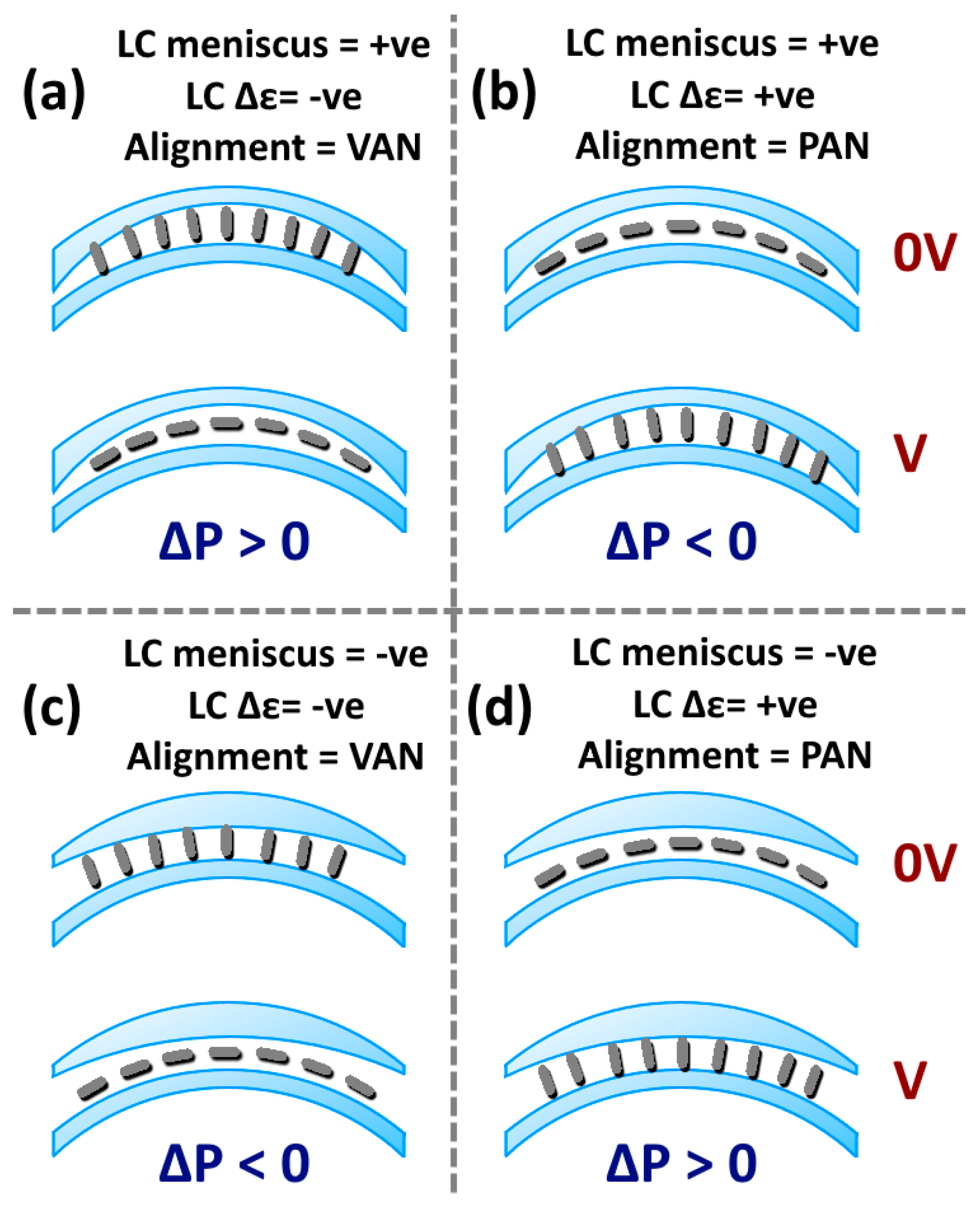
  • Vertical aligned nematic (VAN), where LCs with a negative ∆ε must be used.
  • Planar-homogeneous aligned nematic (PAN), where LCs with a positive ∆ε must be used.
  • Hybrid aligned nematic (HAN), where either LCs with a positive or negative ∆ε can be used.
For simplicity, the same VAN, PAN and HAN notation will also be used for their comparable alignments in a contact lens. Each of these alignment techniques requires a preferential direction to be defined using an alignment layer. This can be obtained by rubbing an appropriate polymer, or through photo alignment techniques. PAN generally requires both sides of the cell to be rubbed to ensure good alignment, although the use of graphene electrodes was found to be an exception to this, as the material is capable of inducing weak planar alignment without rubbing [21]. PAN is the most common geometry used so far [18,19,21]. Both HAN and VAN require only one side of the cell to be preferentially aligned [20]. VAN has already been tested in a LC contact lens and was found to show excellent alignment [17,20]. A small tilt away from the homeotropic condition was induced to preferentially align the liquid crystal when switching this device. Without this tilt the LC would re-orientate into a Schlieren texture and result in scattering [35].
HAN is another possible mode [36], which would in principle be faster switching than either PAN or VAN [35] because the splay-bend of the director. However, the optical phase difference between the ON and OFF states for the HAN is approximately halved for a lens of the same spacing [31,35]. The refractive index at one of the interfaces would be unchanged regardless of switching the device (ne or no for negative or positive ∆͛ materials respectively). Therefore the change in focal power is diminished when compared to the PAN and VAN alignment modes.
Most lenses have been designed with alignment applied linearly, but axial and radial configurations have also been considered [37,38]. This arrangement reduces field-induced defects within the lens that cause unwanted scattering, by allowing the director to follow the circular symmetry of the alignment layers throughout the switching [38]. However, it is the most challenging alignment mode to manufacture. Rubbing techniques are impractical, so photo-alignment must be used to prepare these complex geometries [39,40] and has yet to be tested in an LC contact lens.

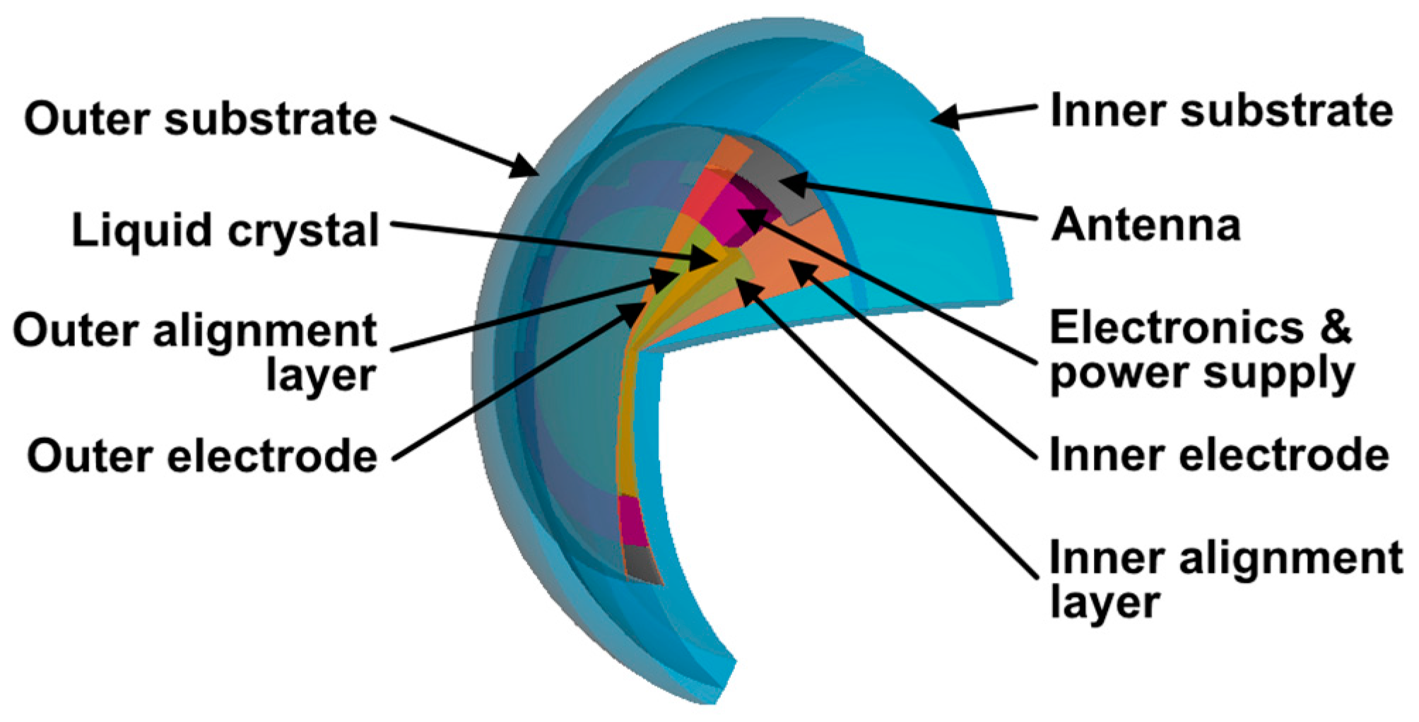
3.1. LC Contact Lens Designs

A contact lens device will not undergo a change in focal power if the inserted LC layer has a uniform optical path length nd. This will only decrease/increase the optical path difference of light passing through the device, without any additional lensing [41]. Therefore, the LC layer must have its own lensing power if the whole device is able to actively change its optical power.
A liquid crystal layer can provide a variable lens element using one of four different approaches to change the optical path length throughout the lens.
(1)
Concave or convex solid LC lenses: The LC layer is shaped into a curved, or other lensing geometry; the so-called “solid lenses” [18,19,20,21,42].
(2)
LC diffractive zone plate: The zones are designed so that the ordinary refractive index of the liquid crystal is matched to that of the polymer. Lensing occurs when the LC is switched to create a phase grating [43,44].
(3)
Fresnel shaped LC lens: Use of a Fresnel lens geometry, where a Fresnel lens structure is index matched to the ordinary index of the liquid crystal [45,46].
(4)
Electrode patterned LC lenses: The LC layer is evenly spaced and is switched so that it produces a gradient refractive index propagating radially from the lens axis. Lensing is typically achieved by generating a parabolic voltage profile that the LC director then follows [6,47,48,49,50].
These designs are discussed in further detail in the following sections.

3.2. Concave or Convex Solid LC Lenses

The solid lens approach is the one described by Milton et al. [18,19,20,21,42]. At least two substrates are needed to enclose the LC lens layer within the whole device and as either or both of these substrates can be individually shaped they will also lens independently from the whole device (illustrated in Figure 4). However, the cavity within these substrates must also be shaped into a lens shape for the LC layer to occupy when the device is filled. The total focal power of the device can be deduced using the thin lens equation [40].
1 f T o t a l =   1 f 1 +   1 f LC +   1 f 2
where fTotal is the total focal power of the whole device, f1 is the focal power of the bottom substrate, fLC is the focal power of the LC lens layer and f2 is the focal power of the top substrate. The total focal power of the device is made negligible if the focal powers of the combined substrates are equal and opposite to the focal power of the LC layer, with a so-called balanced optical system [49] Such an approach would be useful for those who only require visual correction for presbyopia and not distance vision. At least one of the substrates must have positive focal power if the LC layer has a negative focal power, or vice-versa (illustrated in Figure 4). Equation (3) allows the calculation of the approximate focal power when designing this type of device [41]:
P =   ( n 1 n 2 ) ( 1 r 2 1 r 1 )
Here, n1 is the refractive index of the lens, n2 is the refractive index of medium around the lens, r1 is the radius of inner curvature of lens and r2 is the radius of outer curvature of lens. A lens with a positive meniscus and focal power is illustrated in Figure 5.
The dielectric anisotropy of the LC used and the shape of its lens cavity will predetermine how the device functions in the switched OFF state, V = 0; and ON, V >> VC, where VC is the Fréedericksz threshold dictated by the LC elastic constants and dielectric anisotropy and, importantly, is independent of cell gap. Figure 6 illustrates how the shape and dielectric anisotropy of the LC layer must be considered when designing the device [38]. Figure 6a,b shows an LC layer with a positive meniscus, whereas (c) and (d) illustrate negative meniscus systems. The dielectric anisotropy, ∆ε of the liquid crystal in (a) and (c) is negative, whereas it is positive in (b) and (d). LC layers with positive or negative ∆ε are aligned as Vertically Aligned Nematic (VAN) or Planar Aligned Nematics (PAN) respectively for the appropriate device. Using a negative ∆ε LC material within a positive meniscus will result in a positive change in focal power. This is due to the observed refractive index switching from no to ne as the LC reorients from perpendicular to parallel to the substrates. The LC lens layer has a positive focal power, which increases by switching the lens as ne > no. Alternatively, there is a reduction in focal power when using a positive ∆ε material in a positive meniscus geometry as the observed refractive index changes form ne to no. Likewise, there is a reduction in focal power when using a negative ∆ε material that is in a negative meniscus shape. This is due to the magnitude of its negative power of magnification increasing when switching from no to ne. Best operation requires high ∆n LC to be used, wherein a +2D requires a typical minimum cavity spacing of about 30 μm. The solid lens designs depicted in Figure 6 are the simplest to manufacture, but it require higher quantities liquid crystal and will have a longer switching time than other, lower spacing lens designs based on diffractive optic structures (detailed later).
The LC cavity should be kept as thin as possible in order to keep the switching time of the device minimal. This can be achieved by minimizing the difference in LC thickness, which is equivalent to minimizing the radius of curvature between the top and bottom on the LC lens cavity (illustrated in Figure 7). For the solid lens geometry (Fresnel geometries are discussed later), the maximum spacing required of the lens ΔY is calculated by [42].
Δ Y = r 1 r 2 r 1 2 x 2 + r 2 2 x 2
where r1 is the inner radius of curvature (about 7.8 mm [18]), r2 is the outer radius of curvature, x is the aperture (about 2.5 mm for human eye [1]) and the refractive index is assumed to be constant in the plane perpendicular to the axis of the lens. However, the device needs to be able to switch by +2D for adequate correction for presbyopia. The limits are predetermined by the birefringence Δn of the LC used in the lens. Equation (3) can be used to calculate the lens power for ne and no so the change in focal power is determined:
Δ P =   Δ n ( 1 r 2 1 r 1 )
where r1 is the inner radius of curvature and r2 is the outer radius of curvature, and ∆n′ is the difference in refractive index induced by the applied field, and approaches the birefringence ∆n of the LC for high fields. There is no optical power ∆P = 0 for the case where r2 = r1, regardless of switching of the liquid crystal. Equation (5) may then be re-arranged to deduce the radius at the outer curvature of the lens required for a ±2D change in focal power ΔP:
r 2 = Δ n   r 1 Δ n +   Δ P   r 1
Substituting r 2 into Equation (4) generates Figure 8, in which an aperture radius x = 2.5 mm [1] and an inner radius r1 = 7.8 mm [18] were used as they are consistent with the cornea human eye. Equation (4) can be used to calculate the minimum gap within the LC layer ΔY, assuming that the refractive index is switching between ne and no. The plot in Figure 8 [38,42] shows the required ΔY (with an aperture radius x = 2.5 mm and an inner radius r1 = 7.8 mm) with respect to Δn’ to enable ±1.5D, ±2.0D and ±2.5D changes in focal power. This demonstrates that the lens cavity spacing can be made lower if a LC with a larger Δn is used, which is the intuitive result.
Contact lenses with the four basic geometries shown in Figure 6 have been realized in practice [38]. The best performance was found using the homeotropic arrangement of Figure 6a, because switching between both ON and OFF states occurred without unwanted domains of differing alignment during the switching transition. Not only do such domains cause optical scattering, but also caused a significant slowing of the electro-optic effect. Results for such a lens are shown in Figure 9.

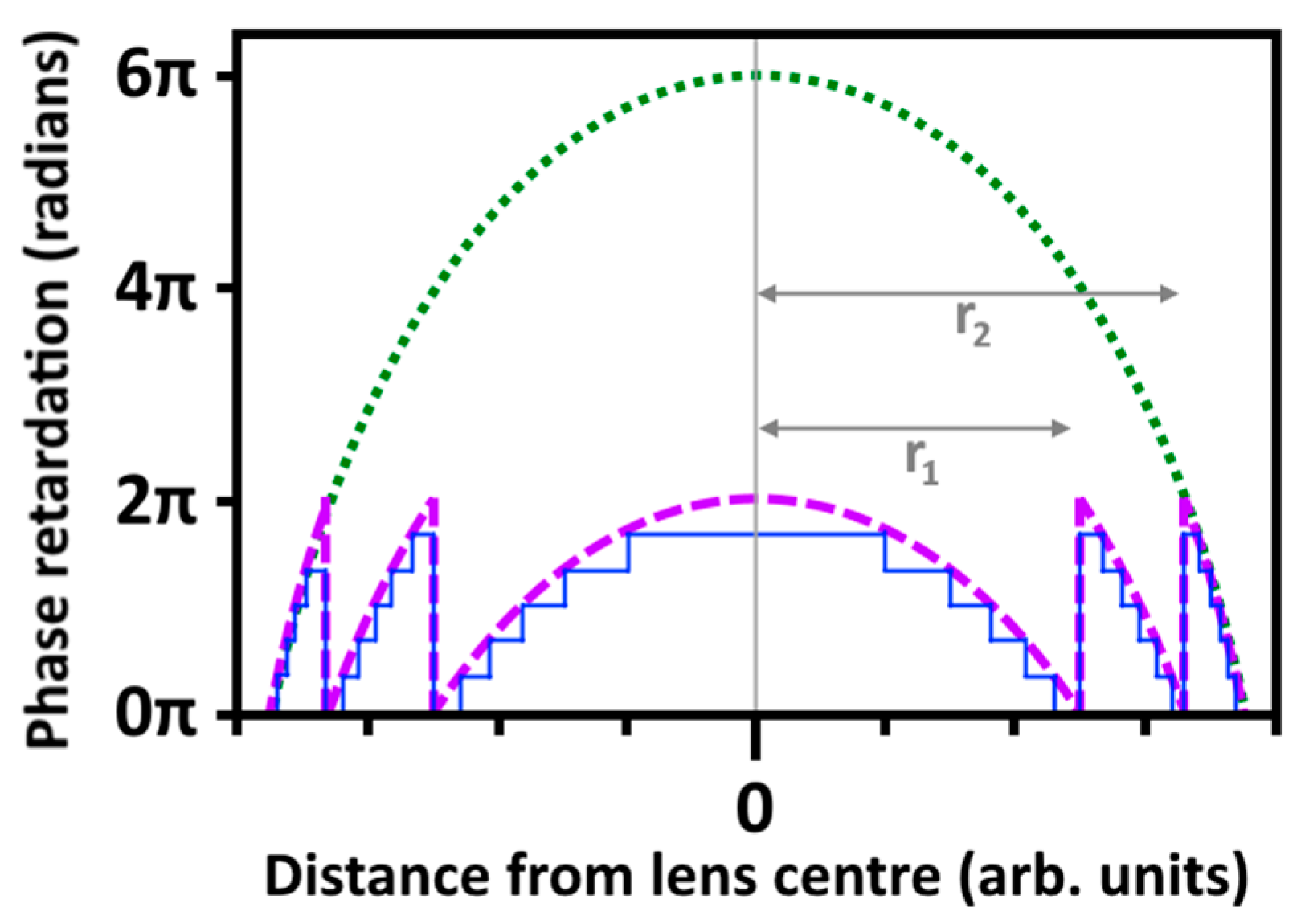
3.3. LC Diffractive Zone Plate

Fresnel optics has been suggested for LC lenses [47,48] and the same principles could be applied to LC contact lenses. This would reduce the cavity spacing and hence volume and response time of the LC layer, when compared to solid lenses. The cavity region alternates between LC and polymer in the following radii pattern (illustrated in Figure 10) [43,44].
r m =   m λ f +   m 2 λ 2 4
where λ is the wavelength of light passing through the lens, f is the focal length and m is the 1, 2, 3, etc. The first order diffraction ring has a radius of 524 μm if it is designed for a wavelength of 550 nm and 2D focal power. Light passing through these types of Fresnel plates requires a phase difference of /4 between the LC and polymer zones for optimum performance. Therefore, the minimum cell gap is 688 nm if the LC birefringence Δn ≈ 0.2 and the polymer is index matched to the ordinary LC refractive index (no). Furthermore, matching the refractive index of the polymer substrate to no prevents diffraction when the LC is in the HAN alignment mode, as there is no phase shift. Both the cell gap and the cavity spacing are fixed to a single wavelength, which results in significant chromatic aberrations when focusing white light [41].
The previous example required the substrate to be patterned to manufacture the zone plate. However, two alternative methods can be used to manufacture the zone plate structure without patterning the substrate directly. The first method is adding polymer stabilized LC to the lens cavity [49]. This polymer stabilized LC is then cured into a zone-plate pattern using photolithography, which results in cured and uncured zone rings. The second method functions by patterning the substrate with alignment polymer and reactive monomers. Photo-stabilization and controlled voltage are applied sequentially to pattern the tilt of the alignment over the surface of the lens [51]. This changes the orientation of the liquid crystal director locally, which is shaped into a diffractive zone-plate, or a Fresnel shaped LC lens.

3.4. Fresnel Shaped LC Lenses

Fresnel shaped lenses use refraction to focus light passing through the lens with reduced thickness of lens, and hence less chromatic aberrations, (since the thinner lenses leads to less wavelength dispersion of the refractive index). This approach uses components of a comparable curved lens segmented into sections, illustrated in Figure 11, to make the lens thinner and therefore likely to be more comfortable to wear [45,46]. A spherical lens design can typically have a minimum cell gap of 30 μm. The cell spacing of a comparable Fresnel system is calculated approximately by replacing the aperture width x in Equation (4) with the radial distance of the Fresnel zones [6].
r m =   2 m λ f
where rm is the radius of Fresnel zone m, λ is the wavelength of light passing through the lens (550 nm is being used for these calculations), f is the focal length of lens (0.5 m is used for calculations herein, corresponding to ∆P = 2D) and m = 1, 2, 3, etc.
The first Fresnel zone at 550 nm occurs at 742 μm, is then substituted into Equation (4) to calculate the approximate cell gap. It was assumed that the inner and outer radius (r1 and r2) are 7.80 mm and 7.24 mm respectively, which corresponds to an equivalent solid lens. The approximate height of the first order Fresnel zone is 3 μm. For a Fresnel shaped LC contact lens, the maximum cavity gap may be ~20 μm so thinner than the solid lens approach (assuming a 5 μm spacer layer). This can become significant given that the whole device must be less than 300 μm thick. As the OFF time is dictated by the spacing squared, d2, it also means that this type of mode can be four times faster than the solid lens approach for a similar ∆n LC. At least one of the substrates that bounds the LC layer must be Fresnel shaped. This, in turn, enables the LC layer to form the negative of the Fresnel lens. Therefore, the LC layer is also a Fresnel lens, but its focal power is switchable. The Fresnel lenses can be designed to have either a positive [45,46] or negative [52,53] focal power. These devices follow a similar convention to those discussed in Figure 2 and Figure 4. Specifically, a positive focal powered substrate would be paired with a negative focal powered LC layer and vice-versa (illustrated in Figure 11). Although in principle faster, more processing is needed to manufacture the Fresnel lens shape, as it is significantly more detailed than a lens using continuous curvature. For simplicity, the electrodes can be arranged under the inactive Fresnel material, meaning that much of the electric field is dropped across the low permittivity plastic [28,54]. This means that the switching fields are both non-uniform and high. Alternatively, the electrode can be deposited on top of the Fresnel structure [46]. However, the contours of the Fresnel shape would result in inhomogeneity in the shape of the electric field.
Defects are also known to nucleate on complex patterned structures [55], particularly where sharp features are required. These can cause substantial scattering and reduce the optical quality of the Fresnel lenses dramatically. Small Fresnel lenses, such as would be the case for contact lenses, suffer from significant aberrations due to the manufacturing tolerances associated with the boundary between adjacent Fresnel zones. This is amplified in liquid crystal devices, where defects at these boundaries cause problems with scattering during operation. Therefore, using Fresnel lenses would increase manufacturing time and cost while giving poorer optical performance.

3.5. Electrode Patterned LC Lenses

Diffractive lenses have also been applied to contact lenses. With electrode-patterned lenses, the diffractive lens designs avoid having to shape the substrates for the contact lenses entirely. Instead, the electrodes used to apply an E field over the lenses are patterned using photolithography [6,47,48,49]. The design principles for these electrodes are illustrated in Figure 12, where two grouped-domains are shown (light and dark blue regions), each containing six diffractive sub-domains. These sub-domains are used to apply a staggered E-field over the grouped-domain they occupy (making the lens profile closer to the Fresnel shaped LC than the zone plate system). Figure 12 illustrates six vias that are orientated radially and used to apply potential to the six separate sub-domains. This potential is also applied to the same relative sub-domains within each grouped domain. For example, the last sub-domain in each grouped-domain can have the same potential applied. This is due to the sizes of both the grouped-domains and the sub-domains being carefully staggered to enable the device to successfully lens. This results in the applied E field varying over the lens (for example the E field for electrodes connects to wires A > B > C > D > E > F, as shown in Figure 12) to get the correct optical properties for the device. Figure 13 illustrates this principle further by showing how the required E-field and radii of each sub-domain corresponds to the multi-level diffractive components of the device. These components contribute towards the kinoform profile of the lens, where both the diffractive and phased properties of the domains are aligned for the best optical properties [56]. This, in-turn, results in the variable refractive properties of the whole lens. The optical power of the entire device is controlled by changing the E field applied to each electrode domain throughout the lens. Ideally, a large number of electrodes would be required to give a smoothly varying index profile and reduce chromatic aberrations. However, this may be negated using resistive vias to control the voltage applied to the electrodes, but greatly reducing the number of voltage levels required [49]. This type of lens is arguably the most complicated design out of all the lenses discussed here, and may be the most difficult to manufacture and control in a contact lens.

3.6. Suitable Electrodes for LC Contact Lenses

The most commonly used electrode in LC devices is indium tin oxide (ITO) [18,19,20]. It has excellent conductivity and transmittance when applied correctly to an adequate substrate. As such, it is also the most common electrode material used in LC contact lens research to date. However, ITO is brittle so its conductivity can degrade on a flexible substrate (such as a contact lens) [57,58]. Furthermore, the conductivity and optical properties of ITO both depend upon its thickness [59,60]. ITO is applied to substrates using sputter deposition, which makes it challenging to form a uniform film onto a curved surface. There has already been significant research into replacing ITO for use on devices mounted onto flexible substrates [61,62,63,64,65,66]. Some of these materials and techniques can be applied to wearable devices, such as contact lenses.
Organic conductors, such as PEDOT:PSS, have already been applied in areas such as organic LEDs [67,68] and solar cells [69,70]. These conductors are cheap and can be solution processed using inkjet printing, screen-printing, spin-coating, etc. [71]. PEDOT:PSS is not as good a conductor as ITO and is less resistant to chemical degradation. Any additional layers (such as alignment layers), must be carefully selected to prevent damage to the PEDOT:PSS electrode. Regardless, De Smet et al. [17] have already demonstrated the use of PEDOT:PSS single pixel LC display contact lens and Bailey et al. [38] demonstrated its use for the correction of presbyopia.
Metallic nano-wires and carbon nano-tubes have been investigated in various plastic electronic applications [63,66,72], but they may not be suitable for LC contact lenses. Like PEDOT:PSS, nano-wires or nano-tubes can be suspended in solvent and solution processed. Their flexibility can be a hindrance, as the wires/tubes can delaminate from the surface over time and cause the device to short circuit. This will stop the LC contact lens from switching and make it unreliable. Furthermore, their conductive properties are dependent upon registration with respect to one another. This is less of a problem when depositing them on a flat surface, but imperfections will appear when depositing them on to a curved substrate and need careful consideration for use in contact lenses [73].
Graphene has already been demonstrated in LCDs [74], offering high conductivity, transmissivity and inherent alignment to the contacting liquid crystal. It has also been used for a LC contact lens with switchable focus by Kaur et al. [21] in a PAN aligned contact lens device. Their graphene electrode was manufactured separately and deposited onto the lens as a suspended mono-layer sheet. The flexibility of graphene (due to having a thickness of only 1 atom) enabled it to conform to the curvature of the substrate. Graphene was demonstrated to work, but its production is still too immature to be used within the immediate future [75].

4. Antenna and Communication

Unless an internal triggering method is adopted, an antenna is required so that a signal can be received by the lenses to indicate when they should be switched OFF or ON. Two LC contact lenses would be needed by each wearer to go into both of their eyes. It would be disorientating if one contact lens switched and the other did not. Therefore, the lenses must be able to communicate with one another independently, with an intermediate device, or both. Due to the restricted geometry of the lens, electric charge sources for implementing switching need to be small, and may need the facility to enable them to be charged if used for more than a few hours. The antenna, therefore, may also serve as a means for recharging the lens power source.
The central area of the contact lens associated with the pupil aperture should be free of any visible components, such as antennae and electronics that would impede the lens performance. Instead, these components need to be positioned in the outer annulus of the lens device, such as shown in Figure 14. A spiraling ring-shaped antenna is best suited for this application as it can loop the periphery of the lens [76]. This type of antenna is already used in the Triggerfish device for health monitoring (shown in Figure 1) [10,77,78]. The antenna is also used as an induction coil to power the device wirelessly. Constantly powering a LC lens via its antenna would be impractical, as the user would have to wear a visible transmitter when in use (such as an emitter placed within spectacle frames, which would defeat the purpose of the contact lens).
The antenna could be incorporated into the lens by either preparing it directly onto the LC lens substrate, or using a separate substrate that is then located within the lens. It must be made from a good conductor such as gold, or silver, to achieve the 50 Ω resistance that is required. Photo-lithography [79], inkjet printing [80,81] and screen printing [82] techniques have each been used for manufacturing antenna.

4.1. Powering the LC Lenses

A switchable contact lens needs to be able to sustain a sufficient voltage across the LC layer during its ON state. It should have sufficient power for at least one day’s use, or longer if the device is not rechargeable. Several methods have been proposed for powering LC contact lenses or similar devices. These include.
  • Batteries: Organic lithium hybrid batteries have been considered for wearable devices due to their high energy storage. These batteries can also be re-charged, which prolongs the longevity of the device. These polymer batteries are flexible and can be solution processed using inkjet printing, dispensing, screen printing, etc. [83,84]. The batteries must be carefully encapsulated to ensure no direct contact with the user. This is because these types of batteries could cause irritation if exposed directly to the user’s eye.
  • Micro super capacitors: The chemical composition of super capacitors is much simpler than a polymer battery. They consist of at least two electrodes, which are separated by a dielectric membrane. For example, Le et al. demonstrated an in-plane capacitor using inkjet printed graphene [85]. The avoidance of hazardous material means that this solution is likely to be more acceptable than polymer batteries. However, at least one day’s charge would need to be stored in the capacitor. Storing large amounts of energy within a capacitor is not as stable as a battery, but it is able to deliver a quick burst of power quickly. Therefore, most of the power could be stored on a battery, which works in tandem with a capacitor when the device needs to be quickly switched on.
  • Enzymatic fuel cells: Eyes are naturally lubricated with saline, which contains enzymes and electrolytes. Extensive work has been conducted into using the energy stored in these electrolytes to power wearable devices [86,87,88,89]. The chemical reaction would eventually deplete from the lenses, but it could be a suitable and passive way to power the lenses.
  • Piezoelectric: Several companies have already been investigating the use of piezoelectric components within wearable devices to harvest energy while the device is being used [13,90]. The eye is constantly moving during blinking, turning, focusing etc. Larger movements, such as the user walking would also stimulate the piezoelectric components to charge the device. A battery or supercapacitor would also need to be included in this design since the piezoelectric components are not capable of constantly providing power. However, this storage component wouldn’t need to able to power the lens for a day by itself, as it would be intermittently recharged by the piezoelectric system.

4.2. Electronics, Interconnects and Vias

Wireless signals are necessary to keep the contact lenses functioning properly. A registered or encrypted signal would be needed to ensure the lens does not accidently switch when a different user with a similar device is nearby. It would also be desirable for the magnitude of the switchable focal power to be programmed to the user’s needs. For example, not all users will require the full ±2D visual correction and having a large array of different lens designs would be more expensive. Programming the lenses to use the appropriate voltage for an intermediate level could tailor the lens to the user’s needs. Furthermore, “waking” the lens from a low power state should be considered so the lenses have a longer shelf life when kept in storage before use [91]. All of these requirements demand that the lens has some kind of processor or logic system integrated into the device.
Any electronics used for computing and power management would need to be prepared outside of the lens (illustrated in Figure 14) as they would be made from silicon. The antenna, power supply and processor electronics could all be fabricated onto the same piece of silicon to form an Application-specific integrated circuit (ASIC). This could be shaped into an annulus beyond the region of the lens required for vision. It would still need sufficient miniaturization to remain inconspicuous; an essential requirement for any contact lens circuitry, particularly when the lenses are chosen for cosmetic reasons. However, progress in this continues, as evinced by the Triggerfish device. Power regulation and communication are used in a broad range of electronic devices (not just wearables), so various off-the-shelf components are already available that are suitable for use in LC contact lenses.
Electronic interconnects would be required as the lens is made from many different components, not all of which can be mounted onto the ASIC. This also includes the electrode layers used to drive the liquid crystal elements. Both wires and vias can be formed using photo-lithography, sputtering using a mask and inkjet printing. These components would be out of the field of view, and high conduction metals could be used such as gold, silver or copper to minimize the visibility of the components. Most contact lens wear has some cosmetic element so ensuring that the associated electronics are inconspicuous is an important part of the device design.

4.3. Triggering Mechanisms

The simplest way of switching the lenses would be using an external device. This could include a dedicated fob, a smart watch, or a smart phone [92]. Existing wireless technologies such as NFC, Bluetooth or Wi-Fi could be used. There are already off-the-shelf components for these types of systems and many widely used devices (such as smart phones) are manufactured with those technologies already included. Having a user-controlled system reduces the risk of unwanted switching, which could be disorientating and dangerous. However, it would always require the user to carry a paired device to switch the lenses. Furthermore, these external devices would also need to be charged and functioning in order to switch the lenses.
Blink detection has also been considered as a semi-autonomous method for switching the LC contact lenses. A predetermined sequence of blinks, closing your eyes for a set period of time, or squinting could be used to control the lens without using an external device [93,94]. This would need to be distinguishable from “normal” blinking and activities such as sneezing. However, it shouldn’t be significantly different so that the operator’s facial expressions appear obscure when switching their lenses.
Passive switching, which senses how the eyes would focus on an object normally, has also been considered. For example, proximity sensors could help determine when the eyes converge during the accommodation process as they focus on a near object [95]. The pupil also changes size when focusing on near objects and could be used as a switching mechanism [96]. These sensors would need to be very accurate and reliable so they do not trigger the lens to switch incorrectly.

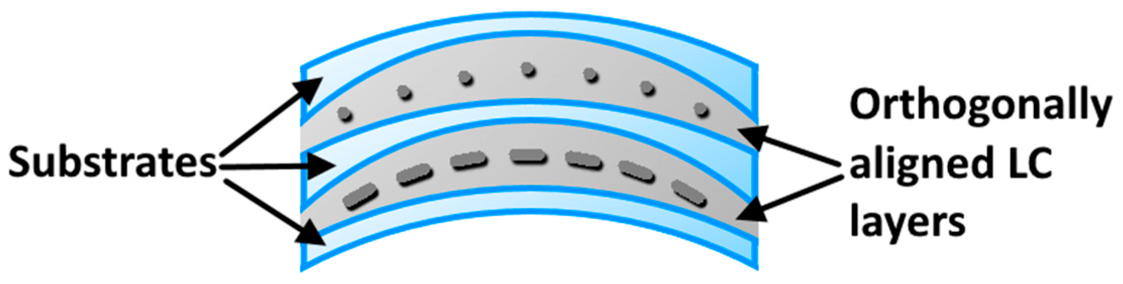
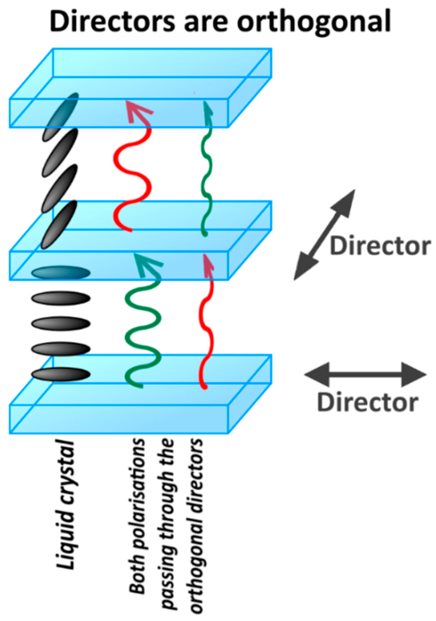
4.4. Polarisation Independence

The birefringence of the LC is being used in these devices to change the focal power of the lens. However, in certain geometries, the very fact that the LC is birefringent results in two focal lengths (one due to ne and the other due to no refractive indices), e.g., when the LC is aligned parallel to the encapsulating lens substrate [19]. In such a case, the lens would produce a blurred image superimposed onto the sharp image, which would be unacceptable to the user. Furthermore, the wearer would inherit the same uncomfortable problems if using a poorly designed LC contact lens. The simplest technique to resolve this problem is to remove the focal point cause by the no refractive indices, so only the ne focal point is observed. This could be achieved by placing a polarizer in front of the lens [20]. Re-orientating the liquid crystal perpendicular to the surface leads to only no being observable, so the device is still able to change its focal power. Including a polarizer is less than ideal as more than 55% of the light is lost due to the absorbed polarization [41]. Furthermore, it would be equivalent to continuously wearing sunglasses and could be dangerous in poorly lit environments. It would also make using devices that already use a polarizer (such as LCD displays) more difficult to operate.
Either using a chiral nematic LC [97] or blue-phase LC [98,99] has been considered as a route to lens operation that is polarization independent. The pitch of the chiral LC needs to be shorter than the wavelength of light transmitting through the sample. This is to ensure that the chiral structure of the LC isn’t beam steering the light along its chiral structure or undergoing Bragg reflection. Instead, the pitch must be smaller than the optical diffraction limit so the light transmits through the LC medium as if it were an isotropic material. A voltage is applied to the lens to unwind the pitch of the LC. A fully unwound LC helix would be aligned perpendicular to the electrodes if it has a positive ∆ε and the applied electric field is much higher than the associated chiral nematic threshold field EH given by [100]:
E H = π 2 P K 22 ε 0 Δ ε
Unlike the nematic Fréedericksz transition, switching of the chiral nematic is a field effect, and hence dependent on the spacing between the electrodes. For typical values K22 = 5 pN, ∆ε = 30 and the sub-optical pitch P = 200 nm, Equation (9) predicts that the field must be much higher than 7 V/μm. The high resulting voltages required prevents operation of this mode for the solid-lens and Fresnel lens approaches for contact lenses, and is a serious drawback for use of the diffractive optic approach too. Furthermore, as the pitch of the LC is much smaller than the wavelength of light passing through, which results in the light being unable to distinguish the individual ne and no components. Therefore, in the lenses off state, the LC layer has an effective refractive index smaller than ne, which is calculated by [31]:
n = n e 2 + n o 2 2
This reduces the maximum change in focal power as the difference is now Δn = <n>n0. Other Liquid crystal phases offer the potential for polarization independence too. For example, the dark-conglomerate phase formed from certain bent-core liquid crystals exhibits a decrease in the refractive index with increasing applied field, due to the change from an optically isotropic medium to a negatively uniaxial medium with the optic axis parallel to the applied field [101]. The performance of polarization independent lenses has been considered theoretically [102], although currently the temperatures and fields required are too high for practical application.
An alternative method to achieving polarization independence as first used by Berreman [7] and demonstrated for a spectacle lens by Li et al. [103], is to use two overlapping LC chambers within a single contact lens (illustrated in Figure 15, where the solid lens design is used as an example due to its simplicity) [42]. In one of the states, either field ON or OFF, the director is arranged to be in the plane of the lens, with orthogonal director profiles in the two chambers. Polarized light passing through the device will pass through the first LC layer in which the plane of polarization is parallel to ne so that lensing occurs. In the second chamber, the director is parallel to the plane of polarization and the light experiences the no refractive index, for which there is no further lensing. Assuming the same LC is used in both chambers, the device is optimized when the cell gap of both is matched, so the optical path difference for the whole device is the same (illustrated in Figure 16). Therefore, the focal power of this two-chamber device, when using the thin lens approximation is:
1 f T o t a l =   1 f S u b 1 + 1 f LC 1 + 1 f S u b 2 + 1 f LC 2 + 1 f S u b 3
where fSub1, fSub2 and fSub3 are the focal lens for their corresponding substrate, fLC1 and fLC2 are the focal lengths for their corresponding LC lens chambers. In the other state, only no is experienced when the LC is switched/aligned perpendicular to the surface in both layers. The total focal power of the lens is polarization independent, regardless of whether it is switched on or off. Clearly, this device is more challenging to fabricate than a single chamber LC lens, not least because the electronics would need to be shared between both chambers, as merging two separate LC lenses into one device would at least double manufacturing costs. Instead, a more complex network of vias would be needed to pass the voltage to the necessary electrode within the entire lens.

4.5. Improving Switching Off Times

It has been previously discussed that some lens designs (such as the solid LC lens), would have slower switching times due to greater LC cell gaps. Faster times for switching the lens on can be achieved by increasing the applied voltage. However, switching the lens off is dependent upon the thickness of the cell and the viscosity of the LC. This is indicated by the following equation of the off response time for an equivalent flat LC cell (not a lens) [30]:
τ o f f = η d 2 ε 0 Δ ε ( V o n 2 V 2 )
where η is the viscosity of the LC, d is the cell gap of a standard LC cell, ε0 is the dielectric permittivity of a vacuum, Δε is the dielectric anisotropy of the LC, Von is the saturation voltage of the LC and V is the voltage being tested. Alternatively, a dual frequency LC could be used where changing the frequency of the applied field changes the response of the LC. Using the appropriate frequency will orientate the extraordinary axis of the LC parallel or perpendicular to the applied field [30]. This would force the LC to orientate into the necessary direction required via and electric field. However, this has yet to be tested in a LC contact lens to determine if results in faster switching times. The fastest reaction time for a young eye is about 0.4 s, after which it takes about 0.6 s to change focusing power. These reaction times will be slower for a typical presbyope. Hence, a target response speed of 1 s is acceptable, which has been achieved through optimization of the alignment mode [38] even for the historically important commercial nematic mixture E7, using axially symmetric alignment to reduce the occurrence of scattering domains. Reference [38] reports an axially-aligned E7 lens with ∆P = 3.0 achieved for 4 V with ON and OFF times of 1 s. Although significantly slower than for lenses with constant spacing (such as those of reference [102], this is acceptable for practical applications, and is readily surpassed through the use of modern, lower viscosity mixtures.

5. Conclusions

The number of people affected by presbyopia continues to rise as the average age of the global population increases. Many sufferers are dissatisfied with the current spectacle and contact lenses options that are available. A liquid crystal contact lens device is one possible route to creating a better method of discrete relief for those who unavoidably live with presbyopia. These electrical devices would be able to correct sight with as few compromises as possible.
A fully functioning LC contact lens suitable for use on the eye has not yet been manufactured. However, the design principles, materials and methods used to make the lenses are already well understood. Pre-existing beam steering devices, wearable technology and electronic miniaturization are all inadvertently contributing towards making a LC contact lens device suitable for mass-market adoption. The device must be comfortable, inconspicuous and easy to operate to become a true improvement over existing lenses.
The choice of whether the lens use a liquid crystal with a positive or negative dielectric anisotropy, filled within a positive or negative lens cavity, is determined by the main function of the lens. For example, a user whose day is dominated by reading or using a computer would benefit more from a lens that defaults to near vision correction when unpowered. Likewise, a user who drives most of the day would benefit from a lens that defaults to distance vision correction when the lens is switched off. This would help the lens last longer as it would use less power than if the alternate mode was preferentially set. Also, it would cause less of a problem for the user if the lens was to lose power due to a depleted battery (for example).
Using a shaped curved or a Fresnel arrangement is far simpler than using an electrode diffractive lens design. The electrode diffractive lens requires extensive patterning, interconnecting wires, vias and power management. A device that uses a Fresnel design is likely to switch faster than a solid LC lens design. The curved shape of the solid LC lens design requires larger average cavity spacing than the Fresnel alternative. However, both approaches would be able to switch between focal points in under a second, so are feasible solutions. Using liquid crystals with a high Δn reduces the spacing of the liquid crystal lens element. Using duel frequency LC’s within these types of lenses has yet to be tested as to whether it can result in shorter switching times. The contact lens application benefits from having a narrow temperature range of typical operation (33 °C to 35 °C) so this approach is more feasible than in wider temperature range devices. Whichever device has the highest performance/cost ratio is likely to be the chosen method for a future product. Polarization independence is an absolute requirement for the LC contact lens device. This can be achieved using chiral or blue-phase LCs, but their high switching voltages make them impractical for this application. Instead, a two-chamber LC system is preferential, despite it being more difficult to produce.
Electrode materials for future flexible and wearable devices can also be applied to LC contact lenses. Currently, the trend is to move away from ITO and into electrodes that do not rapidly decrease in performance when flexed. A future LC lens device would either use ITO (due to its already well understood properties and wide use), polymer conductors, graphene, or a mixture of two or more. Regardless, it has already been shown that a broad range of different electrodes do function for contact lens devices.
Pre-existing smart contact lenses (such as Triggerfish) use electrical induction to power their devices. This isn’t practical for the day-to-day use of a contact lens designed to manage presbyopia. Instead an on-board power system needs to be integrated into the design. There are already several ways in which this might be implemented, but further testing is needed to decide which design is best suited for a contact lens application.
There are several patent families that describe mechanisms that could enable LC lenses to be triggered. Possibilities range from an external wireless control, to proximity sensors to determine the wearer’s direction of gaze. The method likely to be chosen is the simplest for the user to operate, while having a low probability of incorrectly triggering. Having an automatic system would be ideal, but not if it is prone to incorrectly or not triggering at the desired moment. A commercial LC contact lens has yet to be manufactured, but this review has demonstrated that there are several techniques, methods and materials that are useful towards achieving this goal. Everything within this report can be used to make a LC contact lens and their emergence as a commercial product is almost certain. The final lens is not currently limited by an underlying technology that has yet to be developed. Instead, some approaches will perform better than others, albeit each with inevitable compromises. Furthermore, integrating and matching the most complimentary components within a single device is the next change that needed to be overcome. It is a matter of when, rather than if.

Acknowledgments

The authors wish to thank their colleagues Harry Milton, Sarabjot Kaur, John Clamp, Cassie Doherty and Lee Thornton for useful discussions. J.C.J. wishes to thank EPSRC for an Advanced Manufacturing Fellowship (EP/L015188/1) through which J.B. and J.C.J. were funded.

Author Contributions

J.B. wrote the paper under the guidance and inputs of J.C.J. H.F.G. and P.B.M. made various inputs on the physics and optometric aspects of the work, respectively.

Conflicts of Interest

The authors declare no conflict of interest.

References

  1. Madrid-Costa, D.; García-Lázaro, S.; Albarrán-Diego, C.; Ferrer-Blasco, T.; Montés-Micó, R. Visual performance of two simultaneous vision multifocal contact lenses. Ophthalmic Physiol. Opt. 2013, 33, 51–56. [Google Scholar] [CrossRef] [PubMed]
  2. Morgan, P.B.; Efron, N. Contact lens correction of presbyopia. Contact Lens Anterior Eye 2009, 32, 191–192. [Google Scholar] [CrossRef] [PubMed]
  3. Antona, B.; Barra, F.; Barrio, A.; Gutierrez, A.; Piedrahita, E.; Martin, Y. Comparing methods of determining addition in presbyopes. Clin. Exp. Optom. 2008, 91, 313–318. [Google Scholar] [CrossRef] [PubMed] [Green Version]
  4. Blystone, P.A. Relationship between age and presbyopic addition using a sample of 3645 examinations from a single private practice. J. Am. Optom. Assoc. 1999, 70, 505–508. [Google Scholar] [PubMed]
  5. Li, G. Adaptive Lens. Prog. Opt. 2010, 55, 199–283. [Google Scholar]
  6. Li, G.; Mathine, D.L.; Valley, P.; Ayräs, P.; Haddock, J.N.; Giridhar, M.S.; Williby, G.; Schwiegerling, J.; Meredith, G.R.; Kippelen, B.; et al. Switchable electro-optic diffractive lens with high efficiency for ophthalmic applications. Proc. Natl. Acad. Sci. USA 2006, 103, 6100–6104. [Google Scholar] [CrossRef] [PubMed]
  7. Berreman, D.W. Variable Focus Liquid Crystal Lens System. U.S. Patent No. 4,190,330, 26 February 1980. [Google Scholar]
  8. Sato, S. Liquid-crystal lens-cells with variable focal length. Jpn. J. Appl. Phys. 1979, 18, 1679–1694. [Google Scholar] [CrossRef]
  9. Kern, S.P. Variable Power Lens System. U.S. Patent No. 4,601,545, 21 April 1986. [Google Scholar]
  10. Mansouri, K.; Medeiros, F.A.; Tafreshi, A.; Weinreb, R.N. Continuous 24-hour Monitoring of Intraocular Pressure Patterns With a Contact Lens Sensor. Arch. Ophthalmol. 2012, 130, 1534. [Google Scholar] [CrossRef] [PubMed]
  11. Otis, B.; Parviz, B. Introducing Our Smart Contact Lens. Available online: https://googleblog.blogspot.co.uk/ (accessed on 16 January 2014).
  12. Desney, T.; Kristin, T. Functional Contact Lens Monitors Blood Sugar without Needles. Available online: http://research.microsoft.com (accessed on 1 June 2011).
  13. Sako, Y.; Iwasaki, M.; Hayashi, K.; Kon, T.; Nakamura, T.; Onuma, T.; Tange, A. Contact Lens and Storage Medium. Patent Application No. US 2,016,097,940 (A1), 7 April 2016. [Google Scholar]
  14. Kim, D.H. Lens Assembly and Camera Module Including the Same. Patent Application No. US 20,160,178,874 (A1), 23 June 2016. [Google Scholar]
  15. Pugh, R.B.; Higham, C.A. Methods of Using and Smartphone Event Notification Utilizing an Energizable Ophthalmic Lens with a Smartphone Event Indicator Mechanism. Patent Application No. US 20,150,017,918 (A1), 15 January 2015. [Google Scholar]
  16. Pandey, J.; Liao, Y.T.; Lingley, A.; Mirjalili, R.; Parviz, B.; Otis, B.P. A fully integrated RF-powered contact lens with a single element display. IEEE Trans. Biomed. Circuits Syst. 2010, 4, 454–461. [Google Scholar] [CrossRef] [PubMed]
  17. De Smet, J.; Avci, A.; Joshi, P.; Cuypers, D.; De Smet, H. A Liquid Crystal Based Contact Lens Display Using PEDOT: PSS and Obliquely Evaporated SiO2. In Proceedings of the SID Display Week 2012, Boston, MA, USA, 3–8 June 2012; pp. 1375–1378. [Google Scholar]
  18. Milton, H.E.; Gleeson, H.F.; Morgan, P.B.; Goodby, J.W.; Cowling, S.; Clamp, J.H. Switchable liquid crystal contact lenses: Dynamic vision for the ageing eye. In Proceedings of SPIE; Chien, L.-C., Figueiredo Neto, A.M., Neyts, K., Ozaki, M., Eds.; SPIE: Bellingham, WA, USA, 2014; Volume 9004, p. 90040. [Google Scholar]
  19. Milton, H.E.; Morgan, P.B.; Clamp, J.H.; Gleeson, H.F. Electronic liquid crystal lenses for the correction of presbyopia. Opt. Express 2014, 22, 8035–8040. [Google Scholar] [CrossRef] [PubMed]
  20. Syed, I.M.; Kaur, S.; Milton, H.E.; Mistry, D.; Bailey, J.; Morgan, P.B.; Jones, J.C.; Gleeson, H.F. Novel switching mode in a vertically aligned liquid crystal contact lens. Opt. Express 2015, 23, 9911–9916. [Google Scholar] [CrossRef] [PubMed]
  21. Kaur, S.; Kim, Y.-J.; Milton, H.; Mistry, D.; Syed, I.M.; Bailey, J.; Novoselov, K.S.; Jones, J.C.; Morgan, P.B.; Clamp, J.; et al. Graphene electrodes for adaptive liquid crystal contact lenses. Opt. Express 2016, 24, 8782–8787. [Google Scholar] [CrossRef] [PubMed]
  22. Van der Worp, E.; Bornman, D.; Ferreira, D.L.; Faria-Ribeiro, M.; Garcia-Porta, N.; González-Meijome, J.M. Modern scleral contact lenses: A review. Contact Lens Anterior Eye 2014, 37, 240–250. [Google Scholar] [CrossRef] [PubMed]
  23. De Smet, J.; Avci, A.; Beernaert, R.; Cuypers, D.; De Smet, H. Design and Wrinkling Behavior of a Contact Lens With an Integrated Liquid Crystal Light Modulator. J. Disp. Technol. 2012, 8, 299–305. [Google Scholar] [CrossRef]
  24. Flitsch, F.A.; Otts, D.B.; Pugh, R.B.; Riall, J.D.; Toner, A. Biocompatibility of Biomedical Energization Elements. Patent Application No. US 2,016,056,417 (A1), 25 February 2016. [Google Scholar]
  25. Markus, D.T.; Hayes, M. Piezoelectric Energy Harvesting Contact Lens. Patent No. WO 2,016,014,118 (A1), 28 January 2016. [Google Scholar]
  26. Otts, D.; Pugh, R.; Flitsch, F.; Hardy, K. Methods and Apparatus to Form Printed Batteries on Ophthalmic Devices. Patent Application No. US 2,014,002,788 (A1), 2 January 2014. [Google Scholar]
  27. Pugh, R.B.; Ottis, D.B. Ophalmic Lens Media Insert. Patent Application No. US 20,090,244,477 (A1), 26 April 2011. [Google Scholar]
  28. Honoré, F.; Otis, B.; Nelson, A. Reader Communication with Contact Lens Sensors and Display Device. Patent. No. US 8,922,366 (B1), 30 December 2014. [Google Scholar]
  29. Flitsch, F.; Otts, D.B.; Pugh, R.B.; Riall, J.D.; Toner, A.; Davis, S.M. Device and Methods for Sealing and Encapsulation for Biocompatible Energization Elements. Patent Application No. US 2,017,168,318 (A1), 15 June 2017. [Google Scholar]
  30. Goodby, J.W.; Collings, P.J.; Kato, T.; Tschierske, C.; Gleeson, H.F.; Raynes, P. Handbook of Liquid Crystals, 2nd ed.; Wiley-VCH: Weinheim, Germany, 2014. [Google Scholar]
  31. Kumar, S. Liquid Crystals; Cambridge University Press: Cambridge, UK, 2001; ISBN 978-0-521-18794-7. [Google Scholar]
  32. Vicari, L. Optical Applications of Liquid Crystals; Taylor & Francis: Didcot, UK, 2003; ISBN 978-0-7503-0857-1. [Google Scholar]
  33. Yang, D.-K.; Wu, S.-T. Fundamentals of Liquid Crystal Devices; John Wiley & Sons: Hoboken, NJ, USA, 2006; ISBN 0-470-01542-X. [Google Scholar]
  34. Overton, G. US Optical First to Manufacture PixelOptics’ Auto-Focusing Eyeglasses. Available online: http://www.laserfocusworld.com/articles/2011/02/usoptical-pixeloptics.html (accessed on 13 June 1017).
  35. Collings, P.J. Liquid Crystals: Nature’s Delicate Phase of Matter, 2nd ed.; Princeton University Press: Princeton, NJ, USA, 2001; ISBN 0-691-08672-9. [Google Scholar]
  36. Pugh, R.B.; Flitsch, F.A.; Toner, A.; Riall, J.D.; Pandojirao-S, P.; Tabirian, N.V.; Serak, S.; Uskova, O.; De Sio, L. Method and Apparatus for Ophthalmic Devices Including Hybrid Alignment Layers and Shaped Liquid Crystal Layers. European Patent Application EP 2,848,981, 18 March 2015. [Google Scholar]
  37. De Sio, L.; Flitsch, F.A.; Pandojirao-S, P.; Pugh, R.B.; Serak, S.; Tabirian, N.V.; Toner, A.; Uskova, O.; Riall, J.D. Methods and Apparatus for Ophthalmic Devices Including Cycloidally Oriented Liquid Crystal Layers. U.S. Patent No. 9,592,116, 14 March 2017. [Google Scholar]
  38. Bailey, J.; Kaur, S.; Gleeson, H.F.; Morgan, P.B.; Clamp, J.H.; Jones, J.C. Design Considerations for Liquid Crystal Contact lenses. J. Phys. D Appl. Phys. 2017, 50, 485401. [Google Scholar] [CrossRef]
  39. Chen, P.; Lu, Y.-Q.; Hu, W. Beam shaping via photopatterned liquid crystals. Liq. Cryst. 2016, 8292, 1–11. [Google Scholar] [CrossRef]
  40. Mceldowney, S.C.; Shemo, D.M.; Chipman, R.A. Vortex retarders produced from photo-aligned liquid crystal polymers. Opt. Express 2008, 16, 7295–7308. [Google Scholar] [CrossRef] [PubMed]
  41. Hecht, E. Optics, 4th ed.; Addison Wesley: Boston, MA, USA, 2008; ISBN 0-321-11878-0. [Google Scholar]
  42. Milton, H.E.; Kaur, S.; Jones, J.C.; Gleeson, H.F.; Morgan, P.B.; Clamp, J. Liquid Crystal Device and Method Of Manufacture. Patent Application No. US 20,160,170,097 (A1), 16 June 2016. [Google Scholar]
  43. Lester, G.A.; Coulston, S.J.; Strudwick, A.M. Defect-free switchable phase grating. Appl. Opt. 2006, 45, 110–116. [Google Scholar] [CrossRef] [PubMed]
  44. Zhang, Y.; An, H.; Zhang, D.; Cui, G.; Ruan, X. Diffraction theory of high numerical aperture subwavelength circular binary phase Fresnel zone plate. Opt. Express 2014, 22, 27425. [Google Scholar] [CrossRef] [PubMed]
  45. Blum, R.D.; Haddock, J.N.; Kokonaski, W.; Hunkeler, J. Flexible Electro-Active Lens. Patent No. 9,155,614, 13 October 2015. [Google Scholar]
  46. Sato, S.; Suguyama, A.; Sato, R. Variable-Focus Liquid-Crystal Fresnel Lens. Jpn. J. Appl. Phys. 1985, 24, L626–L628. [Google Scholar] [CrossRef]
  47. Valley, P.; Mathine, D.L.; Dodge, M.R.; Schwiegerling, J.; Peyman, G.; Peyghambarian, N. Tunable-focus flat liquid-crystal diffractive lens. Opt. Lett. 2010, 35, 336. [Google Scholar] [CrossRef] [PubMed]
  48. Fan, Y.-H.; Ren, H.; Wu, S.-T. Switchable Fresnel lens using polymer-stabilized liquid crystals. Opt. Express 2003, 11, 3080. [Google Scholar] [CrossRef] [PubMed]
  49. Li, L.; Bryant, D.; Bos, P.J. Liquid crystal lens with concentric electrodes and interelectrode resistors. Liq. Cryst. Rev. 2014, 2, 130–154. [Google Scholar] [CrossRef]
  50. Milton, H.; Brimicombe, P.; Morgan, P.; Gleeson, H.; Clamp, J. Optimization of refractive liquid crystal lenses using an efficient multigrid simulation. Opt. Express 2012, 20, 11159. [Google Scholar] [CrossRef] [PubMed]
  51. Lu, L.; Sergan, V.; Van Heugten, T.; Duston, D.; Bhowmik, A.; Bos, P.J. Surface localized polymer aligned liquid crystal lens. Opt. Express 2013, 21, 7133–7138. [Google Scholar] [CrossRef] [PubMed]
  52. Tse, D.Y.; Lam, C.S.; Guggenheim, J.A.; Lam, C.; Li, K.K.; Liu, Q.; To, C.H. Simultaneous defocus integration during refractive development. Investig. Ophthalmol. Vis. Sci. 2007, 48, 5352–5359. [Google Scholar] [CrossRef] [PubMed]
  53. McFadden, S.A.; Tse, D.Y.; Bowrey, H.E.; Leotta, A.J.; Lam, C.S.; Wildsoet, C.F.; To, C.H. Integration of defocus by dual power fresnel lenses inhibits myopia in the mammalian eye. Investig. Ophthalmol. Vis. Sci. 2014, 55, 908–917. [Google Scholar] [CrossRef] [PubMed]
  54. Lin, Y.-H.; Ren, H.; Wu, Y.-H.; Zhao, Y.; Fang, J.; Ge, Z.; Wu, S.-T. Polarization-independent liquid crystal phase modulator using a thin polymer-separated double-layered structure. Opt. Express 2005, 13, 8746–8752. [Google Scholar] [CrossRef] [PubMed]
  55. Jones, J.C. The Zenithal bistable display: From concept to consumer. J. Soc. Inf. Disp. 2008, 16, 143–154. [Google Scholar] [CrossRef]
  56. Rossi, M.; Kunz, R.E.; Herzig, H.P. Refractive and diffractive properties of planar micro-optical elements. Appl. Opt. 1995, 34, 5996–6007. [Google Scholar] [CrossRef] [PubMed]
  57. Cairns, D.R.; Witte, R.P., II; Sparacin, D.K.; Sachsman, S.M.; Paine, D.C.; Crawford, G.P.; Newton, R.R. Strain-dependent electrical resistance of tin-doped indium oxide on polymer substrates. Appl. Phys. Lett. 2000, 76, 1425–1427. [Google Scholar] [CrossRef]
  58. Park, S.K.; Han, J.I.; Moon, D.G.; Kim, W.K. Mechanical stability of externally deformed indium-tin-oxide films on polymer substrates. Jpn. J. Appl. Phys. 2003, 42 Pt 1, 623–629. [Google Scholar] [CrossRef]
  59. Vasant Kumar, C.V.R.; Mansingh, A. Effect of target-substrate distance on the growth and properties of rf-sputtered indium tin oxide films. J. Appl. Phys. 1989, 65, 1270–1280. [Google Scholar] [CrossRef]
  60. Kim, H.; Horwitz, J.S.; Kushto, G.; Piqué, A.; Kafafi, Z.H.; Gilmore, C.M.; Chrisey, D.B. Effect of film thickness on the properties of indium tin oxide thin films. J. Appl. Phys. 2000, 88, 6021–6025. [Google Scholar] [CrossRef]
  61. Cairns, D.R.; Gorkhali, S.P.; Esmailzadeh, S.; Vedrine, J.; Crawford, G.P. Conformable displays based on polymer-dispersed liquid-crystal materials on flexible substrates. J. Soc. Inf. Disp. 2003, 11, 289–295. [Google Scholar] [CrossRef]
  62. Hohnholz, D.; Okuzaki, H.; MacDiarmid, A.G. Plastic electronic devices through line patterning of conducting polymers. Adv. Funct. Mater. 2005, 15, 51–56. [Google Scholar] [CrossRef]
  63. Langley, D.; Giusti, G.; Mayousse, C.; Celle, C.; Bellet, D.; Simonato, J.-P. Flexible transparent conductive materials based on silver nanowire networks: A review. Nanotechnology 2013, 24, 452001. [Google Scholar] [CrossRef] [PubMed]
  64. Lee, E.H.; Ryu, J.H.; Jang, J.; Park, K.C. Patterned Single-Wall Carbon Nanotube Transparent Conducting Films for Liquid Crystal Switching Electrodes. Jpn. J. Appl. Phys. 2011, 50, 03CA04. [Google Scholar] [CrossRef]
  65. Chan Yu King, R.; Roussel, F. Transparent carbon nanotube-based driving electrodes for liquid crystal dispersion display devices. Appl. Phys. A Mater. Sci. Process. 2007, 86, 159–163. [Google Scholar] [CrossRef]
  66. Kumar, A.; Zhou, C. The race to replace tin-doped indium oxide: Which material will win? ACS Nano 2010, 4, 11–14. [Google Scholar] [CrossRef] [PubMed]
  67. Adawi, A.M.; Connolly, L.G.; Whittaker, D.M.; Lidzey, D.G.; Smith, E.; Roberts, M.; Qureshi, F.; Foden, C.; Athanassopoulou, N. Improving the light extraction efficiency of red-emitting conjugated polymer light emitting diodes. J. Appl. Phys. 2006, 99, 54505. [Google Scholar] [CrossRef]
  68. Shirasaki, Y.; Supran, G.J.; Bawendi, M.G.; Bulović, V. Emergence of colloidal quantum-dot light-emitting technologies. Nat. Photonics 2013, 7. [Google Scholar] [CrossRef]
  69. Caglar, M. Electrical and photovoltaic properties of heterojunction diode based on poly(3,4-ethylenedioxythiophene):poly(styrenesulfonate). Eur. Phys. J. Appl. Phys. 2012, 60, 30102. [Google Scholar] [CrossRef]
  70. Cai, W.; Gong, X.; Cao, Y. Polymer solar cells: Recent development and possible routes for improvement in the performance. Sol. Energy Mater. Sol. Cells 2010, 94, 114–127. [Google Scholar] [CrossRef]
  71. Teichler, A.; Perelaer, J.; Schubert, U.S. Inkjet printing of organic electronics—Comparison of deposition techniques and state-of-the-art developments. J. Mater. Chem. C 2013, 1, 1910. [Google Scholar] [CrossRef]
  72. Lin, H.; Li, L.; Ren, J.; Cai, Z.; Qiu, L.; Yang, Z.; Peng, H. Conducting polymer composite film incorporated with aligned carbon nanotubes for transparent, flexible and efficient supercapacitor. Sci. Rep. 2013, 3, 1353. [Google Scholar] [CrossRef] [PubMed]
  73. Sannicolo, T.; Lagrange, M.; Cabos, A.; Celle, C.; Simonato, J.P.; Bellet, D. Metallic Nanowire-Based Transparent Electrodes for Next Generation Flexible Devices: A Review. Small 2016, 12, 6052–6075. [Google Scholar] [CrossRef] [PubMed]
  74. Blake, P.; Brimicombe, P.D.; Nair, R.R.; Booth, T.J.; Jiang, D.; Schedin, F.; Ponomarenko, L.A.; Morozov, S.V.; Gleeson, H.F.; Hill, E.W.; et al. Graphene-based liquid crystal device. Nano Lett. 2008, 8, 1704–1708. [Google Scholar] [CrossRef] [PubMed]
  75. Yi, M.; Shen, Z. A review on mechanical exfoliation for the scalable production of graphene. J. Mater. Chem. A 2015, 3, 11700–11715. [Google Scholar] [CrossRef]
  76. Lingley, A.R.; Ali, M.; Liao, Y.; Mirjalili, R.; Klonner, M.; Sopanen, M.; Suihkonen, S.; Shen, T.; Otis, B.P.; Lipsanen, H.; et al. A single-pixel wireless contact lens display. J. Micromech. Microeng. 2011, 21, 125014. [Google Scholar] [CrossRef]
  77. Sunaric-Megevand, G.; Leuenberger, P.; Preußner, P.R. Assessment of the Triggerfish contact lens sensor for measurement of intraocular pressure variations. Acta Ophthalmol. 2014, 92, 414–415. [Google Scholar] [CrossRef] [PubMed]
  78. Hubanova, R.; Aptel, F.; Chiquet, C.; Mottet, B.; Romanet, J.P. Effect of overnight wear of the Triggerfish sensor on corneal thickness measured by Visante anterior segment optical coherence tomography. Acta Ophthalmol. 2014, 92, 119–123. [Google Scholar] [CrossRef] [PubMed]
  79. Myny, K.; Tripathi, A.K.; Van Der Steen, J.L.; Cobb, B. Flexible thin-film NFC tags. IEEE Commun. Mag. 2015, 53, 182–189. [Google Scholar] [CrossRef]
  80. Mujal, J.; Ramon, E.; Diaz, E.; Carrabina, J.; Calleja, L.; Martinez, R.; Teris, L. Inkjet printed antennas for NFC systems. In Proceedings of the 2010 17th IEEE International Conference on Electronics, Circuits, and Systems (ICECS), Athens, Greece, 12–15 December 2010; pp. 1220–1223. [Google Scholar]
  81. Rida, A.; Yang, L.; Vyas, R.; Tentzeris, M.M. Conductive inkjet-printed antennas on flexible low-cost paper-based substrates for RFID and WSN applications. IEEE Antennas Propag. Mag. 2009, 51, 13–23. [Google Scholar] [CrossRef]
  82. Roh, J.-S.; Chi, Y.-S.; Kang, T.J. Wearable textile antennas. Int. J. Fash. Des. Technol. Educ. 2010, 3, 135–153. [Google Scholar] [CrossRef]
  83. Gaikwad, A.M.; Steingart, D.A.; Nga Ng, T.; Schwartz, D.E.; Whiting, G.L. A flexible high potential printed battery for powering printed electronics. Appl. Phys. Lett. 2013, 102. [Google Scholar] [CrossRef]
  84. Janoschka, T.; Hager, M.D.; Schubert, U.S. Powering up the future: Radical polymers for battery applications. Adv. Mater. 2012, 24, 6397–6409. [Google Scholar] [CrossRef] [PubMed]
  85. Le, L.T.; Ervin, M.H.; Qiu, H.; Fuchs, B.E.; Zunino, J.; Lee, W.Y. Inkjet-printed graphene for flexible micro-supercapacitors. In Proceedings of the 2011 11th IEEE Conference on Nanotechnology (IEEE-NANO), Portland, OR, USA, 15–18 August 2011; pp. 67–71. [Google Scholar]
  86. Bandodkar, A.J.; Wang, J. Non­invasive wearable electrochemical sensors: A review. Trends Biotechnol. 2014, 32, 363–371. [Google Scholar] [CrossRef] [PubMed]
  87. Barton, S.C.; Gallaway, J.; Atanassov, P. Enzymatic Biofuel Cells for Implantable and Microscal Devices. Chem. Rev. 2004, 104, 4867–4886. [Google Scholar] [CrossRef] [PubMed]
  88. Falk, M.; Andoralov, V.; Blum, Z.; Sotres, J.; Suyatin, D.B.; Ruzgas, T.; Arnebrant, T.; Shleev, S. Biofuel cell as a power source for electronic contact lenses. Biosens. Bioelectron. 2012, 37, 38–45. [Google Scholar] [CrossRef] [PubMed]
  89. Flitsch, F.A.; Otts, D.B.; Pugh, R.B.; Riall, J.D.; Toner, A. Electrolyte Formulations for Use in Biocompatible Energization Elements. U.S. Patent Application 2016/0,056,508 Q1, 25 February 2016. [Google Scholar]
  90. Erturk, A.; Inman, D.J. Piezoelectric Energy Harvesting; John Wiley and Sons: Chichester, UK, 2011; ISBN 978-0-470-68254-8. [Google Scholar]
  91. Humphreys, S.R.; Schweickert, R.K.; Hoggarth, S.P.; Gorji, Z.S.A.; Whitney, D.K., Jr.; Toner, A. Wake Circuit for Powered Ophthalmic Lens. U.S. Patent No. 9,535,266, 3 January 2017. [Google Scholar]
  92. Pugh, R.B.; Toner, A.; Higham, C.A. Energizable Ophthalmic Lens with a Smartphone Event Indicator Mechanism. U.S. Patent No. 9,052,533, 9 June 2015. [Google Scholar]
  93. Pugh, R.B.; Toner, A.; Humphreys, S.R.; Otts, D.B.; Neeley, W.C. Blink Detection System for Electronic Ophthalmic Lens. U.S. Patent Application No. 20,140,320,799 (A1), 30 October 2014. [Google Scholar]
  94. Pugh, R.B.; Toner, A.; Otts, D.B. Electronic Ophthalmic Lens with Lid Position Sensor. U.S. Patent Application 20,140,240,655 (A1), 28 August 2014. [Google Scholar]
  95. Pugh, R.B.; Toner, A.; Otts, D.B. Electronic Ophthalmic Lens with Eye Gaze Sensor. European Patent Application No. EP 2,772,791 (A1), 3 September 2014. [Google Scholar]
  96. Pugh, R.B.; Toner, A.; Otts, D.B. Electronic Ophthalmic Lens with Rear-Facing Pupil Diameter Sensor. U.S. Patent Application No. 20,140,240,665 (A1), 28 August 2014. [Google Scholar]
  97. Large, T.A. Switchable Lens. U.S. Patent No. 5,712,721, 27 January 1998. [Google Scholar]
  98. Li, Y.; Wu, S.-T. Polarization independent adaptive microlens with a blue-phase liquid crystal. Opt. Express 2011, 19, 8045–8050. [Google Scholar] [CrossRef] [PubMed]
  99. Tan, J.; Zhu, J.L.; Ni, S.B.; Wang, Y.J.; Sun, X.Y.; Lu, J.G.; Yang, B.R.; Shieh, H.P.D. Blue Phase LC/Polymer Fresnel Lens fabricated by holographics. J. Disp. Technol. 2014, 10, 157–161. [Google Scholar] [CrossRef]
  100. De Gennes, P.G.; Prost, J. The Physics of Liquid Crystals, 2nd ed.; Clarendon Press: Oxford, UK, 1993; ISBN 0198520247. [Google Scholar]
  101. Nagaraj, M.; Jones, J.C.; Panov, V.P.; Lui, H.; Portale, G.; Bras, W.; Gleeson, H.F. Understanding the unusual reorganization of the nanostructure of a dark conglomerate phase. Phys. Rev. E Stat. Nonlinear Soft Matter Phys. 2015, 91, 042504. [Google Scholar] [CrossRef] [PubMed]
  102. Milton, H.E.; Nagaraj, M.; Kaur, S.; Jones, J.C.; Morgan, P.B.; Gleeson, H.F. Field-induced refractive index variation in the dark conglomerate phase for polarization-independent switchable liquid crystal lenses. Appl. Opt. 2014, 53, 7278–7284. [Google Scholar] [CrossRef] [PubMed]
  103. Li, G.; Valley, P.; Äyräs, P.; Mathine, D.L.; Honkanen, S.; Peyghambarian, N. High Efficiency switchable flat diffractive opthalmic lens with three-layer electrode pattern and two-layer via structures. Appl. Phys. Lett. 2007, 90, 111105. [Google Scholar] [CrossRef]
Figure 1. Triggerfish health monitoring lens device. The gold ringed antenna is used to communicate and power the lens through induction. Image was provided and reproduced with permission by ©Sensimed AG.
Crystals 08 00029 g001
Figure 2. Illustration of how the refractive index of a device and schematic lens changes for specific orientations of the liquid crystal. The ground-state orientation can be controlled by surface treatment and modified by application of a voltage above a threshold.
Crystals 08 00029 g002
Figure 3. Typical alignment modes that can be used in LC contact lenses. Vertically aligned nematic (VAN), Planar aligned nematic (PAN) and hybrid aligned nematic (HAN) are pre-determined by the alignment layer and must be matched with an LC with the appropriate dielectric anisotropy.
Crystals 08 00029 g003
Figure 4. Illustration of lens design principles if one of the switching modes provides no change in focal power. The total focal power of the substrates must if negative if the LC layer has a positive meniscus (top image). Conversely, the substrates must have a positive focal power if the LC layer has a negative meniscus (bottom image).
Crystals 08 00029 g004
Figure 5. Simple lens with a positive meniscus and focal power, with notation that corresponds to the equation for a lens (Equation (3)).
Crystals 08 00029 g005
Figure 6. Schematics of how the different possible LC lens shape and dielectric permittivity influence how the device functions. Captions (a,b) have a positive meniscus LC cavity, whereas (c,d) have a negative shaped meniscus. (a,c) are filled with LCs with negative dielectric anisotropy, whereas (b,d) have a positive dielectric anisotropy. The focal power of the LC cavity is greatest when the LC is aligned parallel to the surface, and the sign of ∆P indicated is that which results from the switching between the OFF and ON states. This predetermines whether the change in focal power (ΔP) is positive or negative when the LC is reoriented after a sufficiently high voltage is applied to the device.
Crystals 08 00029 g006
Figure 7. Diagram to calculate the cavity spacing of the lens when using Equation (4).
Crystals 08 00029 g007
Figure 8. Plot of the maximum change in focal power with respect to the cavity spacing of the lens [38,42]. Increasing the birefringence of the LC enables a smaller gap to be used to achieve the same change in focal power.
Crystals 08 00029 g008
Figure 9. Example of a contact lens formed in PMMA that uses a convex solid geometry based on homeotropic homogeneous alignment [38]. Shown below are the 0 V and 7 Vrms images taken through the contact lens for objects at 5 cm and 15 cm distances. In this example, a positive meniscus lens with the geometry of Figure 6a has been used, so that applying the field causes a +2D optical change as required for the presybope. The focal distances used here do not represent what the eye would see, since much of the focusing is still done by the presbyopic lens.
Crystals 08 00029 g009
Figure 10. LC cavity split into Fresnel zones, resulting in a diffractive lens. The inner and outer curvatures of the cavity are the same (r1 = r2), and their separation creates a phase difference of π.
Crystals 08 00029 g010
Figure 11. Comparison of simple lenses when constructed using a Plano-convex, or Fresnel lens substrate. The encapsulated LC layer forms the negative of the substrate’s lens shape. This enables the focal power to switch between 0D or ±2D if the lens is carefully designed.
Crystals 08 00029 g011
Figure 12. Design principle of a diffractive lens. The lens has multiple electrode domains, each with their own sub-domains. Each domain is equivalent to each concentric zone in a Fresnel plate. The sub-domains are used to radially vary the potential so transmitted light is diffracted. Therefore, each sub-domain is wired to its successive equivalent in the larger domains [6].
Crystals 08 00029 g012
Figure 13. Plot demonstrating the relationship between the phase retardation of light passing through the lens with respect to its distance from the center. The green dotted line indicates the refractive profile, the purple dashed line is the kinoform profile, and the solid blue line is a multi-level diffractive profile [6].
Crystals 08 00029 g013
Figure 14. Illustration of the basic design principles for an LC contact lens. The LC is encapsulated between two substrate lenses. Both of the substrates are coated with electrode and alignment layers on their inner surfaces. The electronics (processor, power supply and antenna) are kept out of the central region of the lens so they do not block the wearer’s vision.
Crystals 08 00029 g014
Figure 15. Negative meniscus substrates encapsulating orthogonally aligned positive meniscus LC layers to achieve a polarization independent device.
Crystals 08 00029 g015
Figure 16. Polarization independence is achieved by aligning directors orthogonal to one another in each LC chamber. However, the optical path length (OPL) must be the same for both chambers to keep the phase of polarizations passing through both ne and no orientations in phase with one another.
Crystals 08 00029 g016

