1. Introduction
To date, nematic liquid crystals (NLCs) are very popular and useful electro-optical materials due to their dielectric anisotropy and optical birefringence, which are sensitive to LC alignments, environmental temperature, and driving methods. They are widely applied in various electro-optical devices including spatial light modulators, LC lenses, and displays [
1,
2,
3]. For typical optical phase modulation, a homogeneous LC cell is usually adopted to provide maximum phase retardation (
δ) using the equation
δ = 2π
Δnd/
λ, where
Δn is LC birefringence,
d is cell gap, and
λ is incident wavelength [
4]. Considering that NLCs cells are used as infrared phase modulators, the cell gap usually has a value larger than 10 μm to achieve a completed 2π phase modulation. However, the large thickness of the LC gap is unfavorable for optical response time in LC electro-optical devices except for several other reasons related to LC elastic constants, LC rotational viscosity [
5,
6], and electrically driving methods. Usually, the rising time can be sped up with higher operating voltages. However, the falling time is directly related to the relaxation of LC reorientations and is only controlled by restoring elastic torque. Therefore, the thicker cell gaps have a slow falling time. Recently, polymer network LC (PNLC) cells have been widely studied and demonstrated a fast response time [
7,
8,
9,
10,
11]. In this method, the molecules of an anisotropic monomer like RM257 possessing an LC building block structure are usually doped with LCs and processed with UV exposure, so that the generated polymer networks provide constraints to LCs to effectively speed up the falling time during the relaxation of LC molecular reorientations. However, light scattering occurs due to the refractive index mismatch of polymer networks and LC microdomains [
1]. The degree of light scattering can be reduced by using much smaller LC microdomains via optimal processing conditions such as monomer concentrations and photopolymerization conditions [
9,
10,
11,
12,
13]. Several studies have demonstrated scattering-free PNLC phase modulators at near infrared wavelength [
14,
15,
16,
17].
Holographic exposure based on optical interference spatially generates very fine and directionally periodic interference patterns with a pitch of a few hundred nanometers. Many studies used this process to fabricate optical-scattering-free electro-optical LC devices such as holographic polymer-dispersed LCs [
18] and polymer LC polymer slices [
19]. In our previous work, we adopted the holographic exposure via a low-power He–Ne laser to expose the anisotropic monomer RM257-doped LC cells to generate holographic polymer networks and to realize a LC phase modulator with low light scattering and ultra-fast response time at visible wavelengths [
13]. However, the operating voltage (185 V
rms) was not suitable for conventional operations. In addition, high operating voltages usually induce an electrostriction effect, that is, electrical deformations of anisotropic polymer networks [
20,
21], which degrades device performance, such as unstable phase modulations with respect to electrical operations. In the present study, PNLC cells processed via holographic exposure were also used to fabricate optical-scattering-free infrared phase modulators with a fast response time. Furthermore, we report a method to reduce operating voltages of infrared phase modulators by varying the ratio of RM257 and N-vinyl-2-pyrrolidinone (NVP). We found that increasing the percentage of NVP dopants successfully reduces operating voltages and the electrostriction effect.
2. Experimental
The LC mixture filled in empty cells (15 μm gap thickness, purchased from Chipset Technology, Miaoli, Taiwan) for homogeneous LC cells contained the following: NLCs (E7, Daily Polymer, Kaohsiung, Taiwan), anisotropic monomer (RM257, HCCH, Yangzhong, China), photo-initiator (H-Nu-Blue-640, Spectra Group Limited, Millbury, USA), co-initiator (Borate-V, Spectra Group Limited, Millbury, USA), and mono-acrylate monomer (NVP, Sigma-Aldrich, St. Louis, USA).
Table 1 shows ingredient ratios of LC mixture filled in experimental PNLC cells for processing holographic exposure. The ingredients of H–Nu–Blue–640 and Borate–V were used to initiate photopolymerization of LC cells when exposed with a He–Ne laser. The anisotropic monomer of RM257 with a rod-like molecular unit possesses behaviors of an LC phase at a temperature range from 70 °C to 126 °C, which is usually photopolymerized with a growth direction of polymer networks along with the direction of LC alignments. NVP was used as a homogenizer to mix H–Nu–Blue–640 and Borate–V to yield a uniform precursor. Thereafter, E7 and RM257 are mixed with the precursor to complete the mixing process of the LC mixture. Furthermore, NVP was also considered as the photocurable monomer and varied percentages with respect to RM257 to improve electro-optical performance of PNLC cells. Except E7, the chemical structures of all other ingredients are shown in [
22].
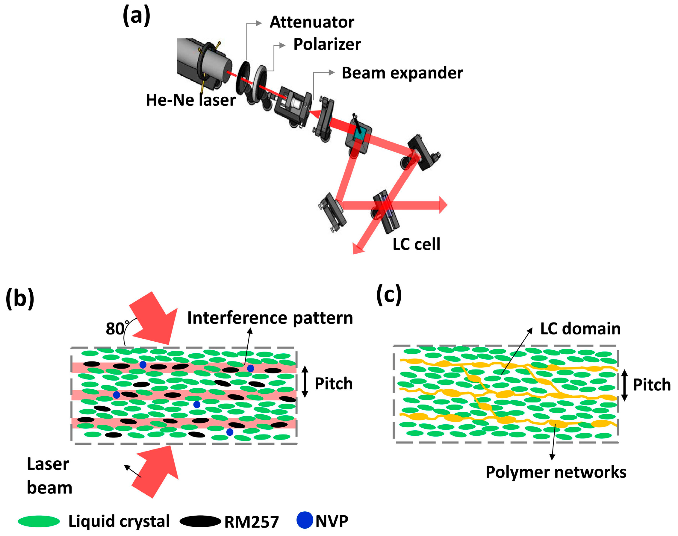
Figure 1a illustrates the setup for processing holographic exposure, where a red He–Ne laser beam (
λ = 632.8 nm, LASOS, Jena, Germany) serially passed through the attenuator, polarizer, and beam expander to achieve an s-polarization light beam with controllable intensity and optical quality. Holographic exposure processes were executed by means of two coherent beams from the previous s-polarization beam passing through a beam splitter with equal power intensity (0.1 mW/cm
2) to expose the LC cell. Both interference beams were incident to the LC cell with an angle of 160° between their wave vectors to generate the interference patterns with pitch of 209 nm as shown in
Figure 1b. Due to specific molecular characteristics, the RM257 and NVP monomers were forced to move toward the regions with higher light intensity during holographic exposure processes. Therefore, the interference patterns generated by holographic exposure will possibly lead to the formed morphology of holographic polymer networks in PLNC cells as schematically shown in
Figure 1c. Finally, the smaller LC domains are embedded in polymer networks to achieve light scattering reduction [
13].
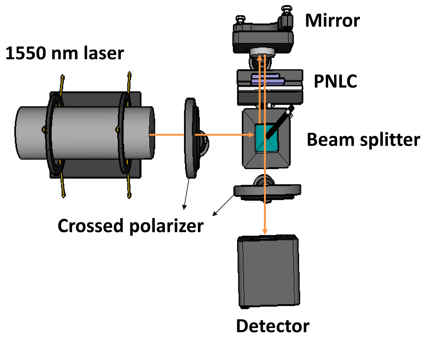
Figure 2 shows the setup used to measure the relative curves of voltage versus optical reflectance (V-R) of completely exposed PNLC cells. In the experiment, we utilized a mirror reflector to reflect the normally incident laser beam (
λ = 1550 nm, THORLABS, Newton, USA) passing through the PNLC cell once. A detector was used to record the final light intensity after passing the PNLC cell twice with respect to applying various AC voltages (10 kHz square waveform) in PNLCs.
3. Results and Discussion
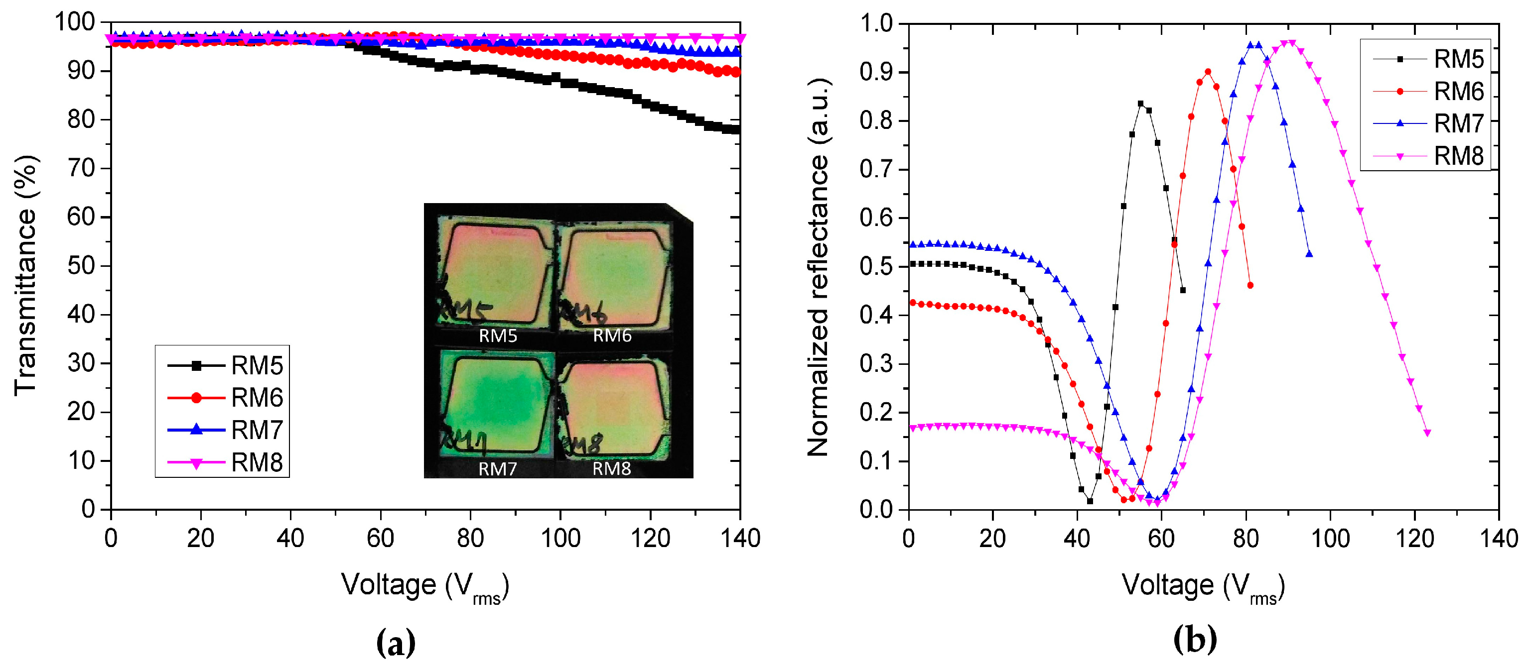
Firstly, intensity loss due to light scattering in the PNLC cells was measured. Without a pair of crossed polarizers, a laser beam (
λ = 1550 nm) was normally incident to the completed PNLC cell located 20 cm away from the laser position. An iris was used to prevent scattering light from entering the detector and permit only light intensity along the initial incident direction. The measured transmittance in different PNLC cells with respect to various applied voltages is shown in
Figure 3a, where transmittance in percentage was the transmittance ratios of cells versus the reference LC cell filled with only E7 LCs. The completed PNLC cells with various concentrations of RM257 dopants also possessed well and uniform homogeneous LC alignments as shown in the inserts of
Figure 3a, which are very different from the polymer-dispersed LC cells [
23]. Therefore, all four PNLC cells show good transmittance as high as 97% without applied voltage. A slight decrease of transmittance compared with the cells filled with E7 LCs is from the mismatch of refractive indices, because the ratios of refractive indices between E7 LCs and RM257 are
no,E7 = 1.521/
ne,E7 = 1.747 and
no,RM257 = 1.508/
ne,RM257 = 1.687 at
λ = 589 nm, respectively. When electrically operating completed PNLC cells, the micro size LC domains appeared that induced the light scattering in the LC cell, but the samples RM7 and RM8 maintained the high transmittance even at a voltage of 140 V
rms. Although, using holographic exposure to process LC cells usually improves light scattering, positive results are also related to the concentrations of the RM257 dopant. If RM257 is used with too low a concentration, it will not decrease light scattering as shown by the experimental results of the RM5 and RM6 cells.
Figure 3b shows the measured V-R curves for four experimental PNLC cells, where optical reflectance was normalized to the maximum reflectance in a reference cell filled with only E7 LCs. Generally, the generated polymer networks after holographic exposure in the PNLC cells provide more constrains to LC molecules to increase operating voltages
V2π for 2π phase modulation and
Vth for threshold voltages. Furthermore, the voltages of
V2π and
Vth are mainly related to the morphology of the polymer networks and the size of LC microdomains [
24,
25]. Especially, the value of
Vth approximately satisfied the equation
Vth = (
d/
D) ×
Vth,
LC [
26], where
d is the cell gap,
D is the average LC microdomains, and
Vth,LC is the threshold voltages of cells filled with LCs. By referred to [
24,
25], the higher concentrations of monomer dopant in cells usually generate smaller LC microdomain sizes. Therefore, the values of
V2π and
Vth are increased in the PNLC cells with higher concentrations. Although the RM7 and RM8 PNLC cells show good performance of V-R curves, the voltages of phase modulation
V2π are also too high for ideal operations, which are 98 V
rms and 123 V
rms, respectively.
The PNLC cell labeled RM5 possessed a low phase modulation voltage of 65 V
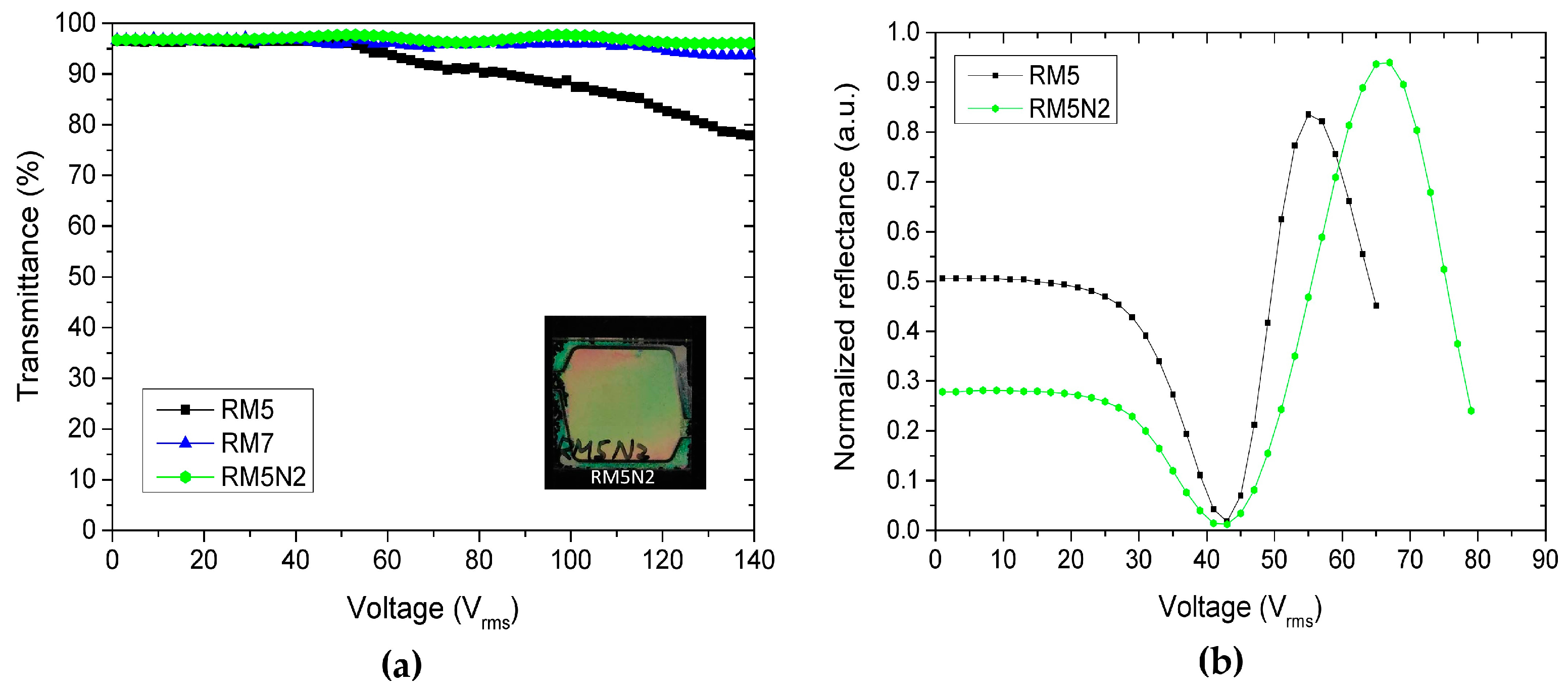
rms but suffered more serious light scattering and inaccurate phase modulation control. Therefore, further investigations were based on the conditions of the RM5 cell to improve optical performance. Due to considerations of NVP as the photocurable monomer with various percentages instead of RM257 to improve performance of PNLC cells, we doped more than 2 wt% NVP instead of RM257 in the previous RM5 cell and labeled it RM5N2 to possibly induce a different polymer network morphology.
Figure 4a shows the comparisons of transmittances in RM7, RM5, and RM5N2 PNLC cells. Obviously, the RM5N2 cell showed very similar results to the RM7 cell, the more than 2 wt% NVP doped in the RM5N2 cell possibly achieved much smaller LC microdomains than the RM5 cell but close to the microdomain sizes in the RM7 cell. Compared with the RM257 dopant with LC building block structure, the NVP dopant has no such structure to provide homogeneous LC alignments. However, doping the RM5N2 cell with more than 2 wt% NVP still assisted and maintained a uniform LC alignment as shown in the insert of
Figure 4a.
Figure 4b shows the comparisons of measured V-R curves in RM5 and RM5N2 cells, where the phase modulation voltage was 79 V
rms in the RM5N2 cell, which was higher than the RM5 cell. A high phase modulation voltage was needed due to the much smaller LC microdomains in the RM5N2 cell.
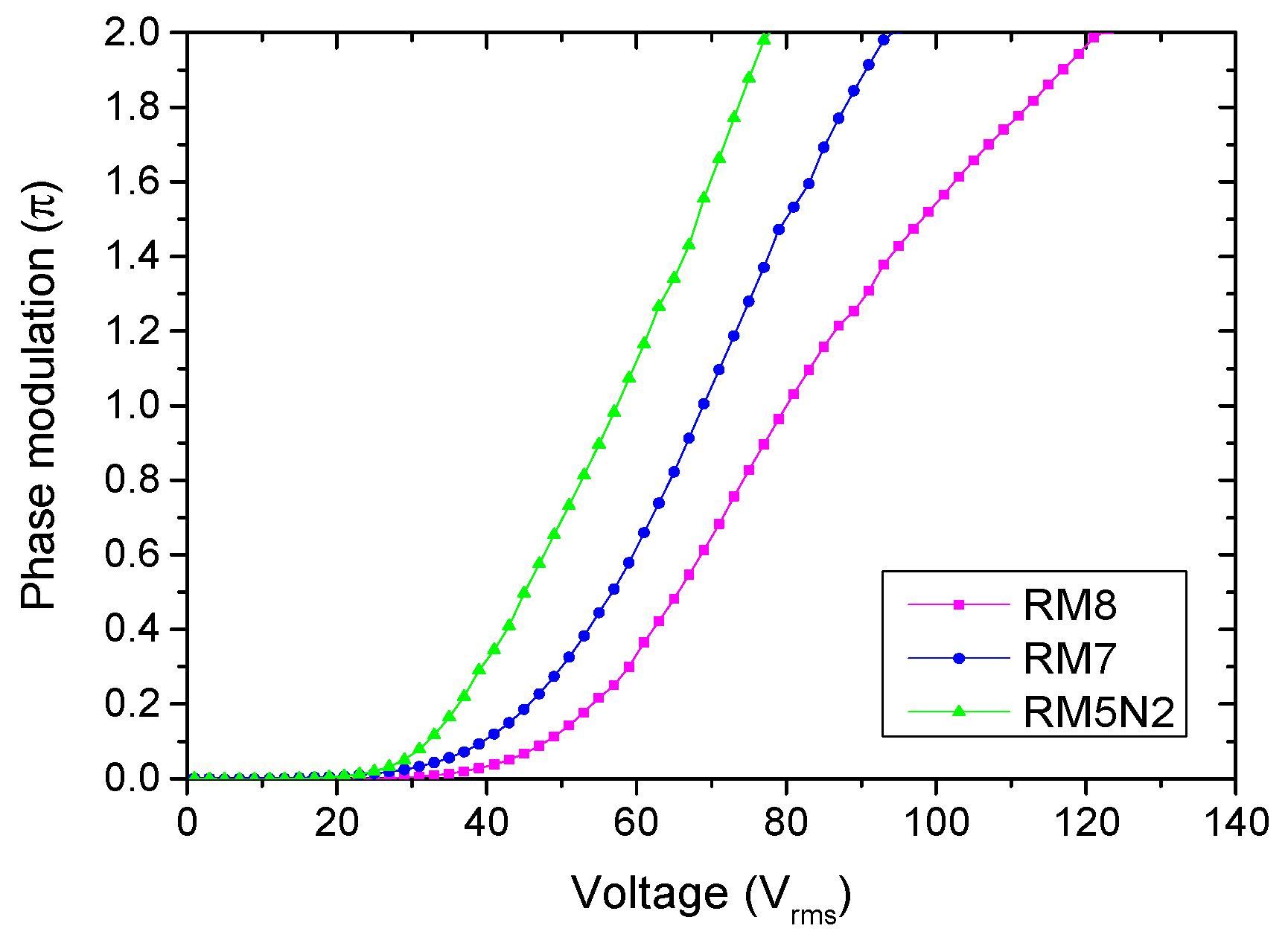
Figure 5 shows the profiles of phase modulation versus applied voltages in RM8, RM7, and RM5N2 PNLC cells as infrared phase modulators. The major phase modulation voltages are listed and summarized in
Table 2. As a result, the RM5N2 cell possessed a low phase modulation voltage due to the more than 2 wt% NVP dopant, which reduced constrains between LC molecules and generated polymer networks.
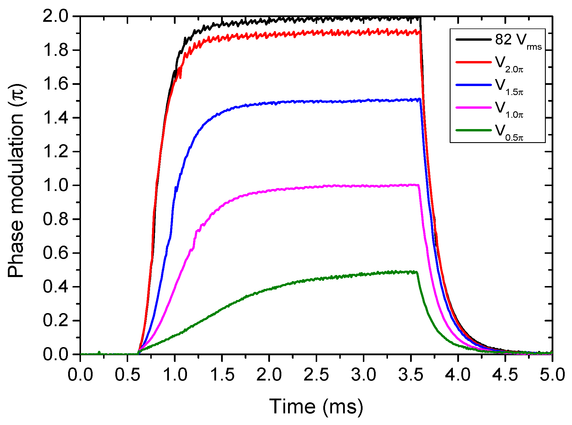
Except for the previous statements to describe characteristics of the fabricated infrared phase modulators, their optical response time was further measured and described in the following. According to experimental results in
Figure 5 and
Table 2, the completed phase modulators (i.e., RM7, RM8, and RM5N2 cells) were electrically switched between on and off states with respect to various applied voltages corresponding to individual phase modulations (i.e., 0.5π, 1.0π, 1.5π, and 2.0π) in the 4 ms duration.
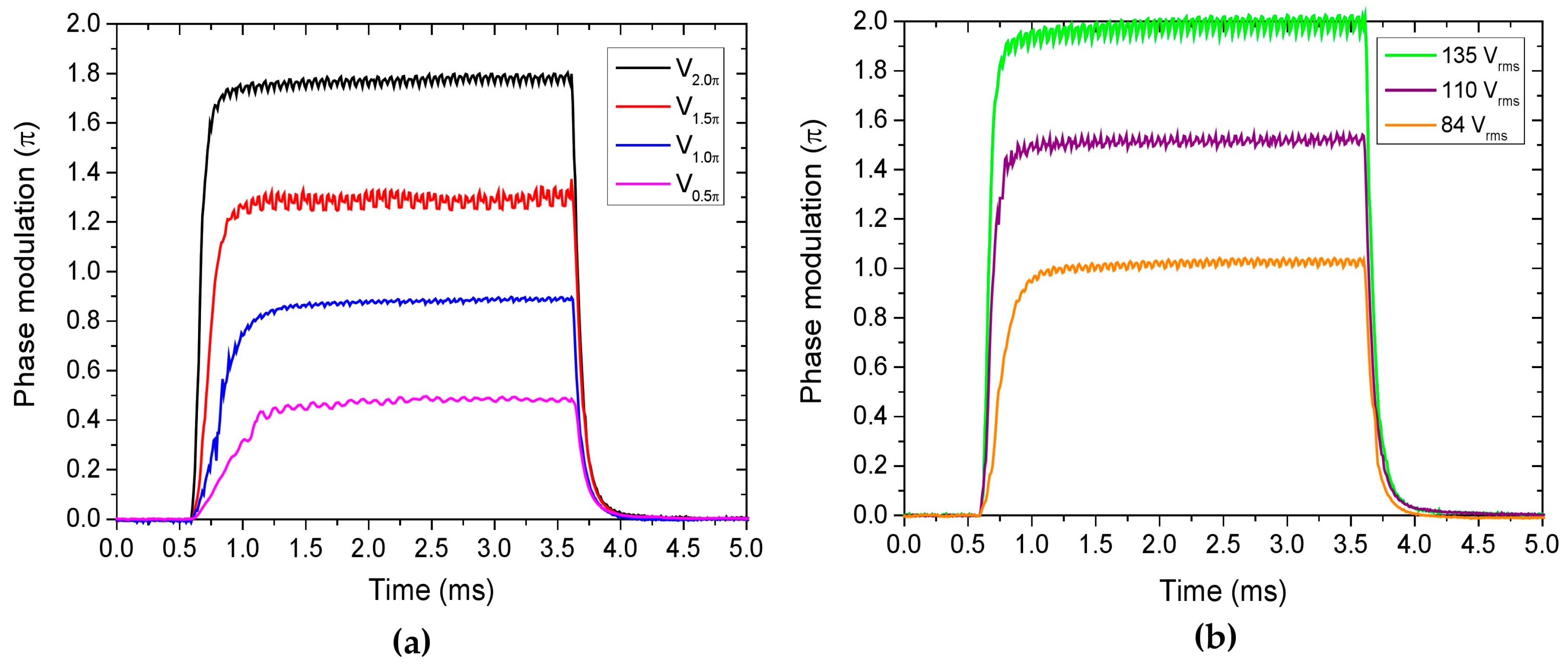
Figure 6a shows the response time of phase modulations in the RM8 cell with respect to four applied voltages. Some ideal values of modulated phase were not achieved if phase modulation voltages were applied according to the data in
Figure 5, including the switching voltages of
V1.0π,
V1.5π, and
V2.0π. This issue was mainly attributed to the electrostriction effect of polymer networks. We obtained the phase modulation voltage
V2π in PNLC cells via measurements of V-R curves and 1 s waiting time for each data point. During measurements of V-R curves, the anisotropic polymer networks generated by the RM257 dopant were continuously deformed due to higher electrical voltages, which also provided the phase variations in PNLC cells. Due to short operation time in real phase modulations, the polymer networks were not seriously deformed to induce unstable phase modulation control as previously described. The ideal and correct phase modulations can be achieved with higher applied voltages [
13] or a longer waiting time (about a few seconds) [
20]. In this study, we applied voltages of 84, 110, and 135 V
rms to ideally achieve the 1.0π, 1.5π, and 2.0π phase modulations as shown in
Figure 6b. Thereafter, measurements of response time, including rising and falling time, were based on applied voltages corresponding to 0.5π, 1.0π, 1.5π, and 2.0π phase modulations. The rising time (τ
r) is defined as the time spent for 0% to 90% phase modulation, and falling time (τ
f) is defined as the time spent for 100% to 10% phase modulation. Response time, phase deviations, and required boost voltages are summarized in
Table 3.
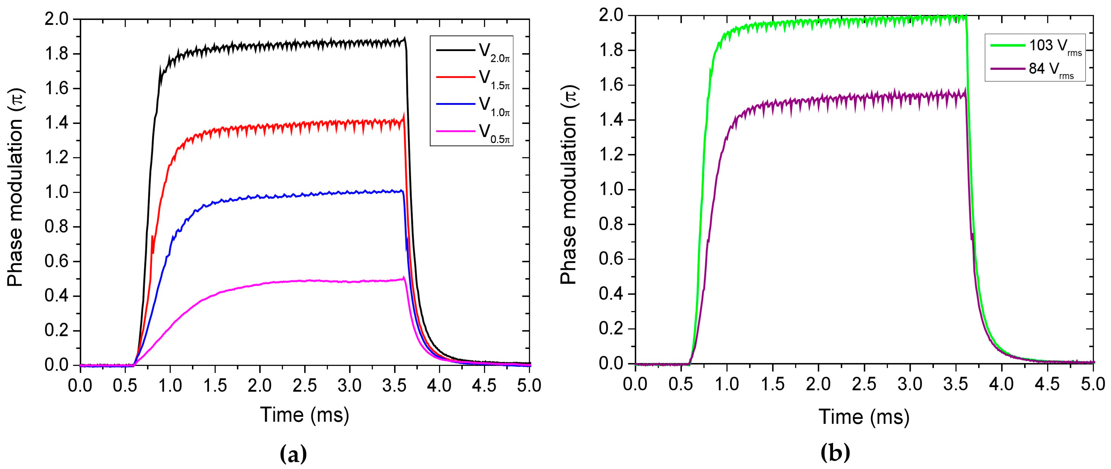
Figure 7 shows the response time of phase modulations in RM7 cells with four applied voltages and the phase deviations for 1.5π and 2.0π phase modulations. Compared with experimental results in the RM8 cell, the phase deviations were smaller, and the required boost voltages were also reduced. The voltages of correct phase modulations of 1.5π and 2.0π were achieved with applied voltages of 84 and 103 V
rms. Finally, the response time of phase modulations in the RM5N2 cell is shown in
Figure 8, which shows only a slight phase deviation (about 0.1π) in the 2.0π phase modulation, and it can be addressed with an applied voltage of 82 V
rms. The electrostriction effect was insignificant because of the low phase modulation voltage in the RM5N2 cell for operating 2.0π phase modulation. Given that polymer networks exist in PNLC cells providing more constrains, the free relaxation time (
τ0) is dependent on the average sizes of the LC microdomains (
D) and approximately satisfied the equation
τ0 =
γ1D2/
K11π
2 [
26], where γ
1 is LC rotational viscosity and
K11 is the LC splay elastic constant. In general, the decay time is similar to
τ0; rising time is more complicated to illustrate but is also related to
τ0 and applied voltage [
6]. Due to larger sizes of LC microdomains generated in the RM7 cell, the average rising time (about 0.66 ms) and falling time (about 0.27 ms) were slower than that in the RM8 cell (0.34 ms rising time and 0.17 ms falling time). According to results in
Figure 4a, the average sizes of the LC microdomains in the RM5N2 cell were possibly close to that in the RM7 cell, but the average rising time (0.88 ms) and falling time (0.40 ms) were slower. It was attributed to the more NVP dopant in the RM5N2 cell that reduced the degrees of constrains between the LC molecules and the polymer networks [
27].


