
Experimental Study on Durability of Hybrid Fiber-Reinforced Concrete in Deep Alluvium Frozen Shaft Lining


School of Civil Engineering and Architecture, Anhui University of Science and Technology, Huainan 232001, China
*
Author to whom correspondence should be addressed.
Crystals 2021, 11(7), 725; https://doi.org/10.3390/cryst11070725
Submission received: 11 May 2021
/
Revised: 11 June 2021
/
Accepted: 21 June 2021
/
Published: 23 June 2021
(This article belongs to the Special Issue New Frontiers in Cementitious and Lime-Based Materials and Composites)
Abstract
:This article proposes hybrid fiber-reinforced concrete (HFRC) mixed with polyvinyl alcohol fiber (PVA) and polypropylene steel fiber (FST) as a wall construction material to improve the bearing capacity and durability of frozen shaft lining structures in deep alluvium. According to the stress characteristics and engineering environment of the frozen shaft lining, the strength, impermeability, freeze–thaw damage, and corrosion resistance are taken as the evaluation and control indexes. The C60 concrete commonly used in freezing shaft lining is selected as the reference group. Compared to the reference group, the test results show that the compressive strength of HFRC is similar to that of the reference concrete, but its splitting tensile strength and flexural strength are higher; according to the strength test, the optimum mixed content of 1.092 kg/m3 PVA and 5 kg/m3 FST are obtained. According to the impermeability test results, the mixing of PVA and FST can improve the impermeability resistance of concrete. For the freeze–thaw cycle test results, the mixing of PVA and FST can improve the frost resistance of concrete; based on the 120 days sulfate corrosion test, the mixing of PVA and FST will improve the corrosion resistance of concrete.
1. Introduction
In coal mining, the vertical shaft is an important channel for moving personnel up and down, ventilation, drainage, and coal lifting [1,2,3], and its supporting structure is called the shaft lining structure [4,5]. When a newly established shaft passes through deep alluvium, it needs to be constructed by a special drilling method. Freezing shaft sinking has the advantages of strong construction adaptability, flexible supporting structure, and fast completion speed; therefore, it has become the main method of construction in China [6,7,8]. In order to resist strong external loads, high-strength concrete is usually selected as the building material for walls in the structural design of frozen shaft lining in deep alluvium, and the outer shaft wall is required to have the characteristics of early strength [9,10]. With the increase in the depth of the well construction, the thickness of the inner and outer sidewalls of the deep alluvium shaft is greatly increased, the hydration heat generated during the pouring of the shaft is high, and the environmental temperature varies greatly during construction, so the high-strength concrete of the shaft lining easily produces temperature cracks [11]. Especially in the method of shaft sinking by freezing in deep alluvium, the freezing pressure on the outer wall of the shaft is obviously unevenly distributed, due to the uneven distribution of the saline flow at the freezing hole deviation, which is extremely adverse to the force on the shaft lining and can easily cause the tensile failure of the high-strength concrete [12,13]. Figure 1 shows the cracks of high-strength concrete in shaft lining.
Frozen shaft lining concrete in deep alluvium has been used under a harsh engineering environment for a long time [14,15,16]. In addition to bearing loads, such as high ground pressure and freezing pressure, the built shaft was also faced with problems, such as water seepage, freezing, and thawing, and the erosion of harmful ions in groundwater [17,18,19,20]. Traditional high strength concrete has obvious deficiencies in impermeability, frost resistance, and corrosion resistance, which is difficult to be applied to such formation conditions as deep alluvium. Therefore, scholars have carried out a series of studies on the durability of shaft lining concrete. In order to solve the problems of many cracks and serious water seepage caused by thermal stress, Yang, L. et al. [21] prepared excellent concrete as a building material for walls by adding hybrid fiber and an expansive agent, and impermeability, crack resistance, and microscopic tests were carried out. The results show that it can solve the problems of shaft lining cracking and water seepage. Zhao, X. M. et al. [22] carried out the study on the frost resistance of fiber reinforced concrete and found that the incorporation of hybrid fiber could improve the compressive strength of concrete after freeze–thaw cycles and reduce the mass loss rate. Yang, D. et al. [23] carried out dry–wet cycle corrosion tests on concrete cube specimens at different corrosion periods. The results show that the splitting tensile strength of concrete decreases continuously with the increase in corrosion depth. Hou, Y. F. et al. [24] analyzed the evolution of concrete corrosion depth by means of ultrasonic testing and microstructure observation, and discussed the factors causing shaft lining concrete corrosion. Liu, J. H. et al. [25] studied the mechanical properties of polypropylene steel fiber-reinforced shaft lining concrete under the coupling action of early stress and negative temperature through a self-made test device, and concluded that concrete’s load-bearing capacity and Cl−1 corrosion resistance were improved.
Based on the above analysis, in this research, experimental studies on the static properties and durability of hybrid fiber-reinforced concrete were carried out to improve the bearing capacity and durability of a frozen shaft lining structure in deep alluvium, based on the frozen wall, Polyvinyl alcohol fiber and polypropylene steel fiber were added to commonly used C60 high-strength concrete to create a high-performance hybrid fiber concrete as a building material for the wall. The research results can provide a scientific basis for engineering applications.
2. Preparation of Hybrid Fiber-Reinforced Concrete for Shaft Lining
2.1. Raw Materials
This study used P.O52.5R cement, which was produced by the Fengyang Conch Cement Plant. The main parameters are shown in Table 1. The coarse aggregate was continuously graded basalt gravel with a 5~20 millimeter particle size; the crushability index was 6.7%, and the mud content was detected before the test to meet the requirements of the specification. The fine aggregate was natural river sand with a mud content of less than 1.6%, which belongs to medium and coarse sand. The fineness modulus is shown in Table 2. Slag powder and silica fume were selected as the mineral admixtures; The slag powder (Anhui Qingya Building Material Co., Ltd., Huainan, China) had a specific surface area greater than 350 m2/kg; The silica fume (Shanxi Dongyi Ferroalloy Factory, Shanxi, China) had a specific surface area greater than 18,000 m2/kg; Table 3 summarizes the mineral composition of the admixture. Moreover, a high-efficiency NF water-reducing agent was used, and its main properties are presented in Table 4. The fiber materials used were polyvinyl alcohol fiber (PVA) and polypropylene steel fiber (FST). Their basic performance parameters are shown in Table 5, and the physical appearance is shown in Figure 2.
2.2. Test Mix Ratio
In order to better resist the effect of uneven freezing pressure, based on C60 high-strength concrete commonly used in freezing walls, a high-performance hybrid fiber concrete was prepared with the addition of PVA fiber and FST fiber. The PVA content and FST content were selected as the two influencing factors of the orthogonal test, and three levels were set for each factor. The PVA fiber content levels were set to 0.728 kg/m3, 1.092 kg/m3, and 1.456 kg/m3; FST fiber content levels were set to 4.0 kg/m3, 5.0 kg/m3, and 6.0 kg/m3. At the same time, another group of reference concrete was set as the control group, resulting in 10 groups of tests in total. The reference mix ratio of the C60 high-strength concrete is shown in Table 6.
2.3. Preparation and Curing of Specimens
Firstly, after weighing, the gravel and sand were poured into a mixer for dry mixing for 2 min; then, cement and admixture were added, and the dry mixing was continued for 2 min; Secondly, the fiber was evenly added in batches, and then stirred for 2 min; Finally, water was added to the mixture quickly followed by slow wet mixing for 2 min.
The slump of the mixture was measured during mixing to evaluate the influence of the hybrid fiber on the fluidity of the concrete. Then, the concrete mixture was poured into a test mold and transported to a shaking table for vibration. The mixture was added or removed according to the situation during the vibration process. It was placed on indoor flat ground for natural curing for 24 h, and the mold was then removed accordingly. After numbering, it was transported to a standard curing box (temperature 20 ± 2 °C; relative humidity 97%) to the age.
2.4. Test Results and Analysis
The specimens were taken out after standard curing for 28 days, and cube compression, splitting tensile, and flexural strength tests were carried out. A CSS-YAW3000 electro-hydraulic servo press was adopted to determine the loading method and rate according to the relevant provisions of CECS13-2009 [26]. Cube specimens of 100 mm × 100 mm × 100 mm were selected for the compression and splitting tensile strength tests, and the results were multiplied by size conversion coefficients of 0.95 and 0.85, respectively. The orthogonal test results are shown in Table 7.
As shown in Table 7, the fluidity of the hybrid fiber concrete is significantly lower than that of the reference group, and the greater the fiber content is, the greater the decrease is. At the maximum content level, the slump is only 160 mm, which is 35 mm lower than that of the reference group; therefore, the amount of hybrid fiber should not be too high, as otherwise, it is difficult to meet the working performance requirements of concrete. The test results of each group show that the compressive strength of the hybrid fiber group is the same as that of the reference group, with an increase of –5.5~3.0%, while the splitting tensile strength and flexural strength are significantly increased compared with those of the reference group, with a maximum increase of 32.4% and 25.6%, respectively. The failure patterns of each group of specimens are shown in Figure 3, Figure 4 and Figure 5.
The comparison of the compressive failure patterns of the specimens in Figure 3, shows that the base concrete was completely crushed, and the fragments fell off, showing the characteristics of brittle failure, while the hybrid fiber-reinforced concrete specimen remained intact and did not break down; only the outer surface was slightly raised and several vertical cracks appeared, similar to hoop failure in the circumferential direction. As can be seen from the comparison of the splitting and tensile failure modes of the specimens in Figure 4, the reference concrete was directly split into two along the center line, while the hybrid fiber-reinforced concrete had vertical cracks along the center line, and the bridging fiber could be seen at the crack section. As shown in Figure 5, flexural strength test, the reference group concrete was directly broken, while the hybrid fiber group showed failure cracks. Thus, hybrid fiber can improve the brittleness of concrete during failure, make it show ductility; and effectively improve the crack resistance of concrete. The analysis shows that PVA fiber has good crack resistance in the early stage, and FST fiber can inhibit crack expansion in the late stage. When the two fibers are mixed, they show a positive hybrid effect, improving toughness, crack resistance, and deformation constraint. Meanwhile, based on the range analysis of the test results in Table 7, obtained using the SPSS software, it was found that the optimal contents of the two kinds of fibers in this experiment were 1.092 kg/m3 PVA fiber and 5 kg/m3 FST fiber, which was determined to be the fiber content of the shaft lining hybrid fiber concrete to be prepared.
3. Durability Test of Shaft Lining Hybrid Fiber-Reinforced Concrete
As the supporting structure of the shaft, the shaft lining will be affected by high-pressure groundwater after the freezing wall is thawed [27,28]. Therefore, the impermeability of high-performance shaft lining concrete must meet certain requirements. The design life of the shaft is usually more than 50 years, and a large number of SO42− and Cl1− are gathered in soil and groundwater in many areas, and the shaft often suffered from freeze–thaw action, so the harsh working environment and long service life put forward higher requirements for the durability of wall material [29,30]. At present, there is a significant amount of research on the durability of fiber-reinforced concrete, but little work on the durability of hybrid fiber-reinforced shaft lining concrete. Therefore, to make the prepared hybrid fiber-reinforced concrete of shaft lining better applied in engineering practice, the durability experiment on shaft lining concrete of reference group and hybrid fiber group was carried out by taking C60 high-strength concrete as the object.
3.1. Impermeability Test
3.1.1. Experimental Design
The ability of concrete to resist seepage under the action of water pressure is called impermeability, which is an important index that reflects the durability of concrete. Based on the GBJ82-2009 [31] specification, a water penetration test was carried out using the penetration height method. A digital display automatic adjusting concrete impervious meter was selected as the measuring device. Additionally, Φ 175 × 185 × 150 cylindrical specimens were selected, with six pieces in each group. The test was carried out after 28 days of standard maintenance of the specimens, and the loading device is shown in Figure 6.
Considering that shaft lining structures are subjected to high underground water pressure in engineering practice, 3.6 MPa was selected to stabilize water pressure, and the following measures were taken during the impermeability test.
- After the maintenance of specimens was completed, the surface of each specimen was polished to remove the influence of surface floating slurry.
- Paraffin was heated and melted in a shallow dish, and then, a layer of paraffin with a thickness of about 1.5 mm was applied around the specimen to seal the water.
- The cylindrical paraffin-wrapped specimen was placed into a preheated metal sleeve die; and left to sink slowly, and then pressed to level with the bottom of the sleeve die.
- After cooling, the specimens were installed in turn, the fixing screws were tightened; and the parameters of the antipermeability meter were adjusted. The loading was set as follows: Upper limit of 4 MPa, lower limit of 3.6 MPa; and the pressure was continuously stabilized for 24 h.
- After the test was completed, the sleeve mold was removed, and a press was used to demold and split the specimen to observe the section. Ten measuring points were taken from each specimen, and the water seepage height at each point was measured. A flow chart of the operation steps is shown in Figure 7.
3.1.2. Test Results and Analysis
After measuring the seepage height of the concrete, the relative permeability coefficient of the concrete was calculated using Formula (1).
where is the relative permeability coefficient of concrete, is the water absorption of concrete (0.03), is the average seepage height of concrete (mm), is the constant pressure time (h), and is the water column height corresponding to the water pressure (1 MPa corresponds to 100 m water column height).
Table 8 shows the average height of water seepage and the calculated relative permeability coefficient of the two groups of specimens after 24 h of pressure stabilization at 3.6 MPa water pressure. It can be seen from Table 8 and Figure 8 that the water seepage height of the two groups of specimens was not large, which indicates that impermeability of both specimen groups is good and meets the impermeability requirements of high-performance concrete. This is mainly because the water–binder ratio is relatively low; at the same time, in the admixture, the slag and silicon powder generated hydration products to improve the compactness of concrete and reduce the number of pores. In addition, the average water permeability height and relative permeability coefficient of the concrete in the hybrid fiber group were significantly lower than those in the reference group, and the average water permeability height was 31.7% lower than that in the reference group. Compared with the reference group, the relative permeability coefficient decreased by 53.3%. This shows that the incorporation of hybrid fiber can further improve the impermeability of concrete.
3.2. Freeze–Thaw Resistance Cycle Test
3.2.1. Experimental Design
Freezing resistance capacity is another important indicator reflecting the durability of concrete. Considering the particularity of the environment in which the structure of a frozen shaft is located, the concrete of the shaft lining should meet certain requirements of freezing resistance [32,33]. The TEST-1000 high and low temperature TEST chamber was selected, and the temperature control range can reach −60 °C~+150 °C. As shown in Figure 9, small cube specimens with a side length of 100 mm were selected for the test. The slow freezing method was adopted to first maintain the specimens in the curing box and then in the water tank. At this time, the water surface temperature no lower than that of the surface of the specimens, and then, they were placed in the test box for freeze–thaw cycle testing. The specimens were frozen at −15 °C for 4 h and then melted in a 20 °C water tank for 6 h. After freezing and thawing, it was regarded as a freeze–thaw cycle.
In this test, the freezing resistance of the C60 benchmark group specimens and those in the hybrid fiber group was studied. The number of freeze–thaw cycles were set as 25, 50, 75, and 100, with three specimens in each freeze–thaw cycle.
3.2.2. Test Results and Analysis
The mass loss rate of concrete specimens was calculated using the following formulas.
where stands for the mass loss rate of the ith specimen after n(n = 0, 25, 50, 75, and 100) freeze–thaw cycles, stands for the mass of the ith specimen before the freeze–thaw cycle stands for the mass of the ith specimen after n freeze–thaw cycles, and stands for the average mass loss rate of each group of specimens after n freeze–thaw cycles (the mass decreases when ; and increases when ).
The results of mass loss are shown in Table 9.
Meanwhile, the relationship of concrete compressive strength and mass loss rate with the number of freeze–thaw cycles were drawn, as shown in Figure 10.
It can be seen from Figure 10 that the mass loss rate of concrete showed a negative value in the early stage and changed slowly, that is, the mass increased slowly. After 75 freeze–thaw cycles, the concrete surface began to shed mud, thus reducing the mass, and the change speed of the specimen mass accelerated. The mass loss in the hybrid fiber group was not significant during the whole freeze–thaw test period, and the mass loss rate after 100 freeze–thaw cycles was 78.3% lower than that of the reference group. With the increase in the number of freeze–thaw cycles, the compressive strength of the two groups of specimens continued to decrease slowly, and the specimens remained in a high–strength state after 100 freeze–thaw cycles. The strength loss rates of the reference group after 25, 50, 75, and 100 cycles were 1.56%, 3.13%, 4.98%, and 8.11%, respectively, and those of the hybrid fiber group were 0.83%, 1.80%, 3.46%, and 5.54%, respectively. The strength loss rate of the hybrid fiber group was 0.73%, 1.33%, 1.52%, and 2.57% lower than that of the reference group, respectively. This can be explained by the fact that the mixture of FST fiber and PVA fiber has a positive hybrid effect, which can effectively reduce the number of micropores in the matrix and improve the antispalling ability of the concrete. Therefore, it can be seen that the incorporation of hybrid fiber can effectively reduce the strength loss of concrete after freeze–thaw cycles and improve the frost resistance of concrete.
A morphological comparison of each group of specimens after 100 freeze–thaw cycles is shown in Figure 11. Many gullies appeared on the surface of the reference concrete group, especially in the corner zone, which is more serious. This is because the concrete freeze–thaw damage generally starts with the spalling of the surface cement mortar, when the deterioration of the reference concrete has already begun. On the contrary, the surface of the hybrid fiber concrete was relatively intact, which indicates that the PVA-FST fiber hybrid can effectively reduce the spalling of concrete subjected to freezing and thawing.
3.3. Sulfate Corrosion Resistance Test
3.3.1. Experimental Design
In addition to bearing complex loads, the shaft lining structure in a long-term deep formation environment is also affected by various harmful corrosive substances gathered in soil and water, among which sulfate is a typical one [34,35]. A long-term immersion method was adopted in this sulfate corrosion resistance test. In order to accelerate corrosion, a 10% NaSO4 solution with mass concentration was selected as the immersion solution, which was prepared from anhydrous sodium sulfate and tap water. And the specimens were soaked in NaSO4 solution after curing, and the soaking time was set as 30d, 60d, 90d, and 120d. In order to ensure that the concentration of the solution was not reduced by crystal precipitation and water evaporation, the solution was replaced regularly (every 30 days in this test). After reaching the expected soaking time, the specimens were washed and wiped dry, and then, the mass loss and strength loss were measured.
3.3.2. Test Results and Analysis
In order to analyze the mass change of concrete after sulfate corrosion, the mass change factor S was defined, and the expression is as follows:
where is the mass variation factor (the mass increases when , and decreases when ), is the mass of the specimen after tage corrosion, and is the mass of the uncorroded specimen.
The results of concrete mass change are shown in Table 10.
Table 10 shows that with the increase in corrosion exposure time, the change factor of concrete mass increases at first and then decreases as the concrete reacts with NaSO4 solution and gradually generates ettringite, gypsum, and other corrosive substances in the initial stage of corrosion [36]. At the same time, some salt crystals invade the specimen and fill the micropores inside the concrete, thus improving the density and mass of the specimen. As the corrosion continues, the filling material inside the specimen continues to accumulate and expand, which destroys the pore structure, produces microcracks and gradually expands; and is accompanied by exfoliation of the epidermis, which finally leads to an increase in the number of cracks and easier invasion of harmful erosion materials; the corrosion is also more serious.
Additionally, compressive strength tests were carried out on the specimens soaked for various periods of time, and the test results at different exposure times are shown in Table 11.
As shown in Table 11, when the corrosion exposure time were 30d, 60d, 90d, and 120d, the strong growth rates of the specimens in the reference group and the hybrid fiber group were 2.8%, 8.3%, 4.4%, and –2.6%, and 2.6%, 6.9%, 7.5%, and 2.1%, respectively. After 120d of corrosion, the strength of the reference group specimens decreased by 2.6%, while the strength of the hybrid fiber group specimens was still in the growth stage, and the strength was 1.076 times that of the reference group, which indicated that the hybrid fiber could effectively slow down the strength loss of concrete after sulfate corrosion. In order to analyze the relationship between the change factors of the compressive strength and mass of concrete specimens and the change in corrosion exposure time more intuitively, the results in Table 10 and Table 11 were drawn into a double-Y-axis, columnar-broken line diagram, as shown in Figure 12.
As can be seen from Figure 12, the mass factor of concrete increased rapidly after 30 days of corrosion exposure time, which involved the process of the filling and compaction of erosive materials in the first stage, but this process obviously slowed down after 60 days. This is mainly due to the increase in expansion stress in the specimen, resulting in the generation and expansion of microcracks, and the decline in mass along with the shedding of the outer skin and cement mortar, and the corrosion of concrete intensified, due to the increase in cracks. Meanwhile, the compaction process of erosive material filling continued; therefore, the mass change factor of concrete still shows an increasing trend, but the rate decreases obviously. At 90d of corrosion, the mass variation factor of concrete in each group reached the maximum value, and at this time, the mass variation factor of concrete in the hybrid fiber group was 44.6% lower than that in the reference group. However, after 90d of corrosion, the deterioration cracking and shedding process intensified, and the mass variation factor of concrete decreased sharply. When the corrosion exposure time was 120 days, the mass variation factors of the two groups of concrete were still positive. However, if the trend is developed, the mass of the two groups of concrete will decrease sharply when the corrosion exposure time is further increased. The compressive strength of the specimens in each group increased first and then decreased with the increase in corrosion exposure time. The initial decrease in compressive strength in the reference group occurred after corrosion for 60 days, while that in the hybrid fiber group occurred after 90 days. This is because the erosive material invades and fills the concrete, the number of pores in the matrix is reduced, the compactness is increased, and the strength is also improved to a certain extent. With continuous corrosion, the filling material in the matrix continues to accumulate and expand, and the expansion stress increases continuously, which eventually exceeds the tensile strength of the concrete, resulting in internal deterioration and cracking, and the pressure-bearing capacity is also reduced. The hybrid fiber can improve the tensile capacity of the matrix, hinder the expansion of cracks and increase the compactness of the concrete; therefore, it slows down the rate of corrosion deterioration to a certain extent.
Overall, after 120 days of sulfate corrosion, there was no obvious mass loss in the reference group and hybrid fiber group, and the compressive strength of the hybrid fiber-reinforced concrete did not decrease but rather even slightly improved. Additionally, the apparent integrity of specimen morphology was relatively high, while the concrete of reference group has obvious surface spalling, as shown in Figure 13. Therefore, the hybrid fiber concrete has good corrosion resistance.
4. Discussion
In this research, according to the static mechanical test, we can see that the flexural strength and splitting tensile strength of the hybrid fiber concrete were significantly higher than those of the reference group, because the bridging effect of the hybrid fiber improves the bond strength between the matrix and the fiber, and hinders the expansion of microcracks and macro cracks in the concrete. This is consistent with the discussion of the strength mechanism of steel fiber reinforced concrete by Liu, J. H. et al. [25]. In the durability test, various properties of the hybrid fiber concrete group were better than those of the reference group. This can be explained by the fact that the mixture of FST fiber and PVA fiber has a positive hybrid effect, which can effectively reduce the number of micropores in the matrix and improves the compactness of concrete so as to resist water pressure penetration, improve the freeze–thaw resistance of concrete, and slow down the speed of sulfate corrosion cracking [21,22]. Therefore, the hybrid fiber concrete prepared is an excellent wall building material for the shaft, which can be applied in engineering practice. Unfortunately, we also acknowledge that there are some shortcomings in this paper. For example, we failed to consider the performance of hybrid fiber concrete under the combined action of freeze–thaw cycles and sulfate. Additionally, we can increase the number of freeze–thaw cycles and extend the exposure time of corrosion tests in the subsequent studies to achieve better test results.
5. Conclusions
In order to improve the bearing capacity and durability of frozen shaft lining structures in deep alluvium, experimental studies on the static properties and durability of hybrid fiber-reinforced concrete were carried out. The static mechanical properties, impermeability, frost resistance, and corrosion resistance of hybrid fiber concrete were studied, and the conclusions are as follows:
- Under the design strength of C60, the compressive strength of the hybrid fiber group was the same as that of the reference group, with an increase of −5.5~3.0%, while the splitting tensile strength and flexural strength were significantly higher than those of the reference group, with a maximum increase of 32.4% and 25.6%, respectively. At the same time, the optimum content of hybrid fiber in this experiment was determined as 1.092 kg/m3 PVA fiber and 5 kg/m3 FST fiber.
- According to the impermeability test results, the average impermeability height and relative permeability coefficient of the hybrid fiber concrete were reduced by 31.7% and 53.3%, respectively, compared with the reference group, which indicates that the hybrid fiber can significantly improve the impermeability of concrete; and enable it to meet the impermeability requirements for frozen shaft lining concrete, which is in accordance with the conclusion of the impermeability test of hybrid fiber conducted by Yang, L. et al. [21].
- Through the freeze–thaw resistance cycle test, it found that after 100 freeze–thaw cycles, the mass loss rate and strength loss of the hybrid fiber concrete were reduced by 78.3% and 2.57%, respectively, compared with those of the reference concrete, which is similar to the results of the freeze–thaw test of fiber-reinforced concrete carried out by Zhao, X. M. et al. [22]. Additionally, the group of hybrid fiber concrete still maintained a higher bearing capacity and a better apparent morphology, which indicates that the hybrid fiber can improve the frost resistance of concrete.
- According to the sulfate corrosion resistance test results, after soaking in sulfate solution for 120 days, the mass and strength of the hybrid fiber-reinforced concrete increased rather than decreasing; its strength still maintained a high level. It shows that hybrid fiber-reinforced concrete has good corrosion resistance and can meet the requirements for long-term use in harsh underground environments.
Author Contributions
Investigation, Y.F. and P.Z.; methodology, Z.Y., Y.F. and X.H.; software, P.Z. and X.H.; data curation, Y.F. and P.Z.; formal analysis, Z.Y, Y.F. and X.H.; writing—originaldraft, Z.Y. and Y.F.; visualization, P.Z. and X.H.; writing—review and editing, Y.F., P.Z. and X.H.; conceptualization, Z.Y.,Y.F. and X.H.; resources, Z.Y.; supervision, Z.Y. and P.Z.; project administration, Z.Y., Y.F. and P.Z.; funding acquisition, Z.Y. and X.H. All authors have read and agreed to the published version of the manuscript.
Funding
This research was supported by the Anhui University Discipline Professional Talented Person (No.gxbjZD09), Anhui Provincial Natural Science Foundation Youth Project (1908085QE185), Anhui Provincial College of Natural Science Research Key Project (KJ2018A0098), Project Funded by China Postdoctoral Science Foundation (2018M642502), and the Science Research Foundation for Young Teachers in Anhui University of Science and Technology (QN2017211).
Institutional Review Board Statement
Not applicable.
Informed Consent Statement
Not applicable.
Data Availability Statement
Not applicable.
Conflicts of Interest
The authors declare no conflict of interest.
References
- Xie, H.P. Research review of the state key research development program of China: Deep rock mechanics and mining theory. J. China Coal Soc. 2019, 44, 1283–1305. [Google Scholar]
- He, M.C. Research progress of deep shaft construction mechanics. J. China Coal Soc. 2021, 46, 726–746. [Google Scholar]
- Yang, H. Design of shaft freezing construction in thick surface soil. Coal Sci. Technol. 2019, 40, 62–64. [Google Scholar]
- Wang, X.S.; Cheng, H.; Wu, T.L.; Yao, Z.S.; Huang, X.W. Numerical analysis of a novel shaft lining structure in coal mines consisting of hybrid-fiber-reinforced concrete. Crystals 2020, 10, 928. [Google Scholar] [CrossRef]
- Jia, C.G. The design of shaft lining structure in extra thick alluvium of deep shaft by freeze sinking method. Mine Constr. Technol. 2019, 40, 1–4. [Google Scholar]
- Wang, J.P.; Liu, W.M.; Wang, H. Comparisions on ground freezing constructions in 1000m depth mine shaft. Mine Constr. Technol. 2017, 38, 34–37. [Google Scholar]
- Li, J.Z.; Gao, W.; Chen, Z.P.; Peng, F. Status and outlook of over C80 high strength and high performance concrete technology applied to shaft liner by freezing sinking method in China coal mine. Mine Construct Techno. 2018, 39, 45–48. [Google Scholar]
- Li, J.Z.; Gao, W.; Li, F.Z. New progress of theory and technology in deep shaft sinking by artificial ground freezing method. Mine Constr. Technol. 2020, 41, 10–14. [Google Scholar]
- Zhang, S.P.; He, P.L.; Niu, L.L. Mechanical properties and permeability of fiber-reinforced concrete with recycled aggregate made from waste clay brick. J. Clean. Prod. 2020, 26, 918–922. [Google Scholar] [CrossRef]
- Yao, Z.S.; Chen, H.; Sun, W.R. Experimental study on high strength composite shaft lining in deep alluvium. J. Rock. Soil Mech. 2003, 5, 739–743. [Google Scholar]
- Zhang, T.; Yang, W.H.; Chen, G.H.; Huang, J.H.; Hang, T.; Zhang, C. Monitoring and analysis of hydration heat temperature field for high performance mass concrete freezing shaft lining. J. Min. Saf. Eng. 2016, 33, 290–296. [Google Scholar]
- Guo, L. Study on the Inhomogeneity of Horizontal Lateral pressure on Shaft Lining. Doctor’s Thesis, University of Mining and Technology, Beijing, China, 2010. [Google Scholar]
- Dai, C. Analysis of Deep Alluvium Freezing Shaft Wall Mechanical Properties. Master’s Thesis, Anhui University of Science and Technology, Huainan, China, 2017. [Google Scholar]
- Jiang, L.H.; Xu, H.D.; Chu, H.Q.; Wang, M.J.; Xu, L. Development and application of high strength and high performance concrete to mine freezing shaft. Coal Sci. Technol. 2010, 38, 38–41. [Google Scholar]
- Peng, S.L.; Rong, C.X.; Cheng, H.; Wang, X.J.; Li, M.J.; Tang, B.; Li, X.M. Mechanical Properties of High-Strength High-Performance Reinforced Concrete Shaft Lining Structures in Deep Freezing Wells. Adv. Civ. Eng. 2019, 21, 69–78. [Google Scholar] [CrossRef]
- Yang, Y. The Preparation and Performance Research of Freezing Shaft Lining C80 HPC in Extraordinary Depth Surface Soil. Master’s Thesis, Anhui University of Science and Technology, Huainan, China, 2006. [Google Scholar]
- Shan, F.D. Common problems and countermeasures in design and construction of mine shaft equipment. Mine Constr. Technol. 2016, 37, 38–40. [Google Scholar]
- Li, Y.; Li, B.; Zhang, L.Y.; Ma, C.; Zhu, J.; Li, M.; Pu, H. Chloride Ion Corrosion Pattern and Mathematical Model for C60 High-Strength Concrete after Freeze-Thawing Cycles. Adv. Civ. Eng. 2021, 6, 32–40. [Google Scholar]
- Xue, W.P. Research on Coupled Damage Evolution Mechanism and Strength Characteristics of Shaft Lining Concrete Under High Pressure Water. Doctor’s Thesis, Anhui University of Science and Technology, Huainan, China, 2017. [Google Scholar]
- Jiang, X.Q.; Cao, D.F.; Ge, W.J.; Zhang, Y. Effect of freeze-thaw cycle and chloride corrosion on bond properties between steel bar and concrete. J. Yangzhou Univ. Nat. Sci. Ed. 2017, 20, 69–74. [Google Scholar]
- Yang, L.; Yao, Z.S.; Xue, W.P.; Wang, X.S.; Kong, W.H.; Wu, T.L. Preparation performance test and microanalysis of hybrid–fibers and microexpansive high-performance shaft lining concrete. Constr. Build. Mater. 2019, 223, 431–440. [Google Scholar] [CrossRef]
- Zhao, X.M.; Li, A.Y.; Qiao, H.X.; Li, J.C.; Wang, X.K. Frost resistance and damage deterioration model of fiber-reinforced concrete. Bull. Chin. Ceram. Soc. 2020, 39, 3196–3202. [Google Scholar]
- Yang, D.; Yan, C.; Liu, S. Spliting Tensile Strength of Concerte Corroded by Saline Soil. ACI. Mater. J. 2020, 32, 137–145. [Google Scholar]
- Hou, Y.F.; You, S.; Ji, H.G. Experimental study on corrosion characteristics of concrete shaft lining by ultrasonic detection. In Proceedings of the 3rd ISRM Young Scholars’ Symposium on Rock Mechanics, Xian, China, 8–10 November 2014; pp. 285–290. [Google Scholar]
- Liu, J.H.; Chen, Z.M.; Ji, H.G. Study of the performance of shaft concrete mixed with imitation steel fiber under the coupling of early age load and negative temperature. J. China Coal Soc. 2013, 38, 2140–2145. [Google Scholar]
- China Standards Publication. Standard Test Methods for Fiber Reinforced Concrete; CECS/13-2009; Standard Press of China: Beijing, China, 2009. [Google Scholar]
- Han, J.H.; Zou, J.Q.; Yang, W.H.; Hu, C.C. Mechanism of Fracturing in Shaft Lining Caused by High-Pressure Pore Water in Stable Rock Strata. Math. Probl. Eng. 2019, 12, 132–140. [Google Scholar] [CrossRef]
- Liu, T.Y.; Zhang, P.; Li, Q.F.; Hu, S.W.; Ling, Y.F. Durability Assessment of PVA Fiber-Reinforced Cementitious Composite Containing Nano-SiO2 Using Adaptive Neuro-Fuzzy Inference System. Crystals 2020, 10, 347. [Google Scholar] [CrossRef]
- Yu, X.F.; Dong, Y.W.; Wang, G.; Lu, H.L. Durability of fly ash concrete against sulfate erosion in complex environment. Concrete 2020, 6, 58–69. [Google Scholar]
- Anwar, A.Y.; Moetaz, E.H.; Khallad, N.; Khan, P.B. Corrosion resistance of recycled aggregate concrete incorporating slag. ACI. Mater. J. 2020, 117, 111–122. [Google Scholar]
- China Standards Publication. Standard for Test Methods of Long–Term Performance and Durability of Ordinary Concrete; GBT/50082-2009; Standard Press of China: Beijing, China, 2009. [Google Scholar]
- Yang, M.F.; Ni, X.Q.; Wang, X. Complex multi function anti-freeze influenced to durability of minus temperature mine shaft liner concrete. Coal Sci. Technol. 2010, 38, 47–49. [Google Scholar]
- Ni, X.Q.; Yang, M.F. Research and application of frost-resistant, impermeable, high-strength and high-flow shaft lining concrete. J. Min. Saf. Eng. 2004, 1, 27–32. [Google Scholar]
- Jiang, J.H.; Wen, W.X.; Qiu, J.Q. Corrosion behaviors of concrete exposed to sulfate attack with simulated groundwater pressure. J. Hebei Univ. Eng. Nat. Sci. Ed. 2019, 3, 11–15. [Google Scholar]
- Limeira, J.; Etxeberria, M.; Agulló, L.; Molina, D. Mechanical and durability properties of concrete made with dredged marine sand. Constr. Build. Mater. 2011, 25, 4165–4174. [Google Scholar] [CrossRef]
- Zhao, L.; Liu, J.H.; Zhou, W.J.; Ji, H.G. Damage evolution and mechanism of concrete erosion at sulfate environment in undergroundmine. J. China Coal Soc. 2016, 41, 1422–1428. [Google Scholar]
Figure 1.
The cracks of high-strength concrete in shaft lining: (a) Temperature cracks caused by temperature stress; (b) Rupture cracks caused by uneven freezing pressure.
Figure 1.
The cracks of high-strength concrete in shaft lining: (a) Temperature cracks caused by temperature stress; (b) Rupture cracks caused by uneven freezing pressure.

Figure 2.
Appearance of fibers: (a) FSTF; (b) PVAF.

Figure 3.
Comparison of compression failure modes of specimens: (a) Reference group; (b) hybrid fiber group.
Figure 3.
Comparison of compression failure modes of specimens: (a) Reference group; (b) hybrid fiber group.
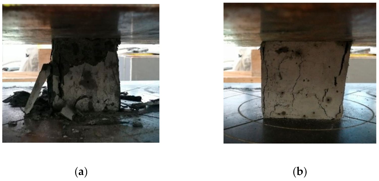
Figure 4.
Comparison of splitting failure modes of specimens: (a) Reference group; (b) hybrid fiber group.
Figure 4.
Comparison of splitting failure modes of specimens: (a) Reference group; (b) hybrid fiber group.

Figure 5.
Comparison of flexural failure modes of specimens: (a) Reference group; (b) hybrid fiber group.
Figure 5.
Comparison of flexural failure modes of specimens: (a) Reference group; (b) hybrid fiber group.
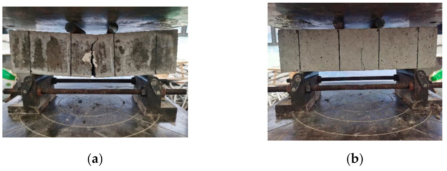
Figure 6.
Impermeable loading device.
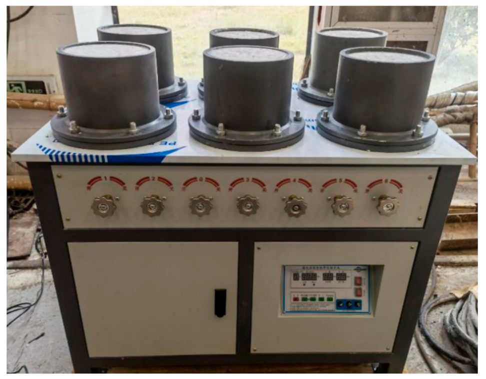
Figure 7.
Process chart of impermeability test. (a) Sample grinding; (b) Sample sealing wax; (c) Sample installation; (d) impermeability test; (e) Take out the sample; (f) Split specimen.
Figure 7.
Process chart of impermeability test. (a) Sample grinding; (b) Sample sealing wax; (c) Sample installation; (d) impermeability test; (e) Take out the sample; (f) Split specimen.

Figure 8.
Concrete seepage height chart: (a) Reference group; (b) hybrid fiber group.

Figure 9.
Freeze–thaw cycle test device.
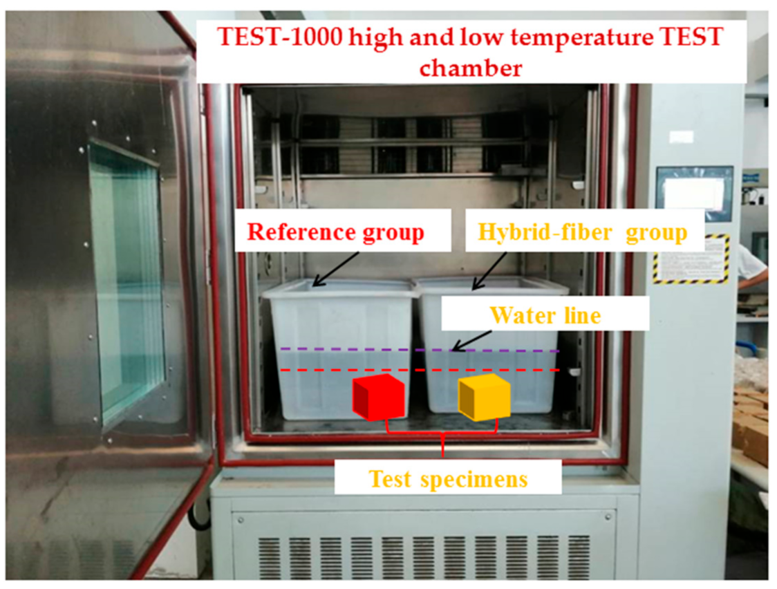
Figure 10.
Relation chart of compressive strength and mass loss factors with the number of freeze–thaw cycles.
Figure 10.
Relation chart of compressive strength and mass loss factors with the number of freeze–thaw cycles.

Figure 11.
Contrast of morphology of concrete after 100 freeze–thaw cycles: (a) Reference group; (b) hybrid fiber group.
Figure 11.
Contrast of morphology of concrete after 100 freeze–thaw cycles: (a) Reference group; (b) hybrid fiber group.
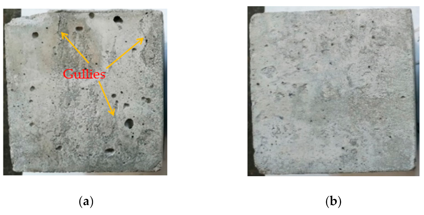
Figure 12.
Relation chart of compressive strength and mass change factor with corrosion.

Figure 13.
Appearance of specimens after 120 d immersion: (a) Reference group; (b) hybrid fiber group.
Figure 13.
Appearance of specimens after 120 d immersion: (a) Reference group; (b) hybrid fiber group.


Table 1.
Main performance parameters of P.O52.5R cement.
| Cement Type | Stability | Setting Time (min) | Flexural Strength (MPa) | Compressive Strength (MPa) | |||
|---|---|---|---|---|---|---|---|
| Initial setting | Final setting | 3d | 28d | 3d | 28d | ||
| P.O 52.5R | Qualified | 120 | 280 | 7.2 | 10.9 | 34.5 | 57.8 |
Table 2.
Fineness modulus of sand.
| Square Screen Size (mm) | Remaining Percentage of Screen (%) | Cumulative Sieve Residual Percentage (%) |
|---|---|---|
| 4.75 | 1.3 | 1.3 |
| 2.36 | 11.0 | 12.3 |
| 1.18 | 13.1 | 25.4 |
| 0.6 | 26.5 | 51.9 |
| 0.3 | 41.8 | 93.7 |
| 0.15 | 3.8 | 97.5 |
| Amount at the bottom of the screen | 2.5 | 100.0 |
| Total | 100.0 | 100.0 |
| Fineness modulus | 2.934 | |
Table 3.
Mineral composition of admixture.
| Admixtures | Component (%) | ||||||
|---|---|---|---|---|---|---|---|
| SiO2 | Al2O3 | Fe2O3 | CaO | MgO | SiO2 | SO3 | |
| Slag powder | 32.41 | 9.99 | 1.50 | 40.32 | 6.86 | 32.41 | 2.51 |
| Silicon powder | 93.60 | 0.78 | 0.65 | 0.82 | 1.30 | 93.60 | 0.10 |
Table 4.
Properties of water reducer.
| Water Reducing Rate (%) | Color | Density (kg/m3) | Chlorideion Content (%) | Solid Content (%) |
|---|---|---|---|---|
| 21 | Yellow | 1410 | ≤0.3 | ≥90 |
Table 5.
Basic performance parameters of fibers.
| Fibers | Length (mm) | Elastic Modulus (GPa) | Elongation (%) | Density (g·cm−3) | Tensile Strength (MPa) |
|---|---|---|---|---|---|
| FSTF | 50 | 5 | 24 | 0.91 | 570 |
| PVAF | 18 | 39 | 6.9 | 1.30 | 1830 |
Table 6.
The reference mix ratio of the C60 high-strength concrete.
| Strength Grade | Water/Binder Ratio | Cement (kg·m−3) | Admixtures (kg·m−3) | Stone (kg·m−3) | Sand (kg·m−3) | Water (kg·m−3) |
|---|---|---|---|---|---|---|
| C60 | 0.28 | 410 | 130 | 1121.5 | 630.8 | 151.2 |
Annotation: Admixtures = Slag powder (102.12 kg·m−3), Silicon powder (20.5 kg·m−3), NF (7.38 kg·m−3).
Table 7.
Orthogonal test results.
| Specimen | Concrete Type | PVA (kg·m−3) | FST (kg·m−3) | Slump (mm) | CS (MPa) | Maximum Error Rate of CS (%) | TS (MPa) | Maximum Error Rate of TS (%) | FS (MPa) | Maximum Error Rate of FS (%) |
|---|---|---|---|---|---|---|---|---|---|---|
| J-1 | Reference concrete | 0 | 0 | 195 | 72.4 | 5.6 | 4.54 | 4.3 | 6.34 | 5.9 |
| H-1 | Hybrid fiber concrete | 0.728 | 5 | 178 | 72.0 | 6.4 | 5.55 | 5.1 | 7.12 | 6.8 |
| H-2 | 1.456 | 4 | 165 | 69.5 | 4.5 | 5.31 | 5.6 | 6.98 | 5.2 | |
| H-3 | 1.092 | 5 | 178 | 74.6 | 5.2 | 6.01 | 5.8 | 7.96 | 6.3 | |
| H-4 | 1.092 | 6 | 174 | 71.5 | 7.1 | 5.25 | 6.9 | 7.01 | 5.7 | |
| H-5 | 0.728 | 6 | 185 | 71.1 | 4.9 | 5.22 | 4.2 | 6.94 | 6.1 | |
| H-6 | 1.092 | 4 | 182 | 70.9 | 5.6 | 5.16 | 6.3 | 6.89 | 5.8 | |
| H-7 | 0.728 | 4 | 187 | 70.5 | 6.7 | 5.58 | 5.5 | 7.28 | 4.9 | |
| H-8 | 1.456 | 5 | 168 | 69.6 | 4.2 | 5.97 | 4.7 | 7.87 | 5.8 | |
| H-9 | 1.456 | 6 | 160 | 68.4 | 3.9 | 5.32 | 4.4 | 7.06 | 4.7 |
Annotation: CS = Compressive strength, TS = Splitting tensile strength, FS = Flexural strength.
Table 8.
Concrete impermeability test results.
| Specimen Groups | Water Penetration Height (cm) | Average Value | Relative Permeability Coefficient (10−7cm/h) | |||||
|---|---|---|---|---|---|---|---|---|
| 1 | 2 | 3 | 4 | 5 | 6 | |||
| Reference group | 2.02 | 1.81 | 1.53 | 1.87 | 1.82 | 1.75 | 1.80 | 0.563 |
| Hybrid fiber group | 1.15 | 0.96 | 1.34 | 1.25 | 1.42 | 1.27 | 1.23 | 0.263 |
Table 9.
Concrete mass loss results after freeze–thaw cycles (%).
| Specimen Groups | Number of Freeze–Thaw Cycles (Times) | ||||
|---|---|---|---|---|---|
| 0 | 25 | 50 | 75 | 100 | |
| Reference group | 0 | –0.10 | –0.16 | 0.02 | 0.23 |
| Hybrid fiber group | 0 | –0.04 | –0.06 | –0.02 | 0.05 |
Table 10.
Mass change factors of specimens at different corrosion exposure (%).
| Specimen Groups | Corrosion Exposure Time (d) | ||||
|---|---|---|---|---|---|
| 0 | 30 | 60 | 90 | 120 | |
| Reference group | 0 | 0.17 | 0.41 | 0.56 | 0.32 |
| Hybrid fiber group | 0 | 0.08 | 0.24 | 0.31 | 0.14 |
Table 11.
Results of compressive strength after sulfate corrosion (MPa).
| Specimen Groups | Corrosion Exposure Time (d) | ||||
|---|---|---|---|---|---|
| 0 | 30 | 60 | 90 | 120 | |
| Reference group | 70.3 | 72.3 | 76.1 | 73.4 | 68.5 |
| Hybrid fiber group | 72.2 | 74.1 | 77.2 | 77.6 | 73.7 |
Publisher’s Note: MDPI stays neutral with regard to jurisdictional claims in published maps and institutional affiliations. |
© 2021 by the authors. Licensee MDPI, Basel, Switzerland. This article is an open access article distributed under the terms and conditions of the Creative Commons Attribution (CC BY) license (https://creativecommons.org/licenses/by/4.0/).
Share and Cite
MDPI and ACS Style
Yao, Z.; Fang, Y.; Zhang, P.; Huang, X. Experimental Study on Durability of Hybrid Fiber-Reinforced Concrete in Deep Alluvium Frozen Shaft Lining. Crystals 2021, 11, 725. https://doi.org/10.3390/cryst11070725
AMA Style
Yao Z, Fang Y, Zhang P, Huang X. Experimental Study on Durability of Hybrid Fiber-Reinforced Concrete in Deep Alluvium Frozen Shaft Lining. Crystals. 2021; 11(7):725. https://doi.org/10.3390/cryst11070725
Chicago/Turabian StyleYao, Zhishu, Yu Fang, Ping Zhang, and Xianwen Huang. 2021. "Experimental Study on Durability of Hybrid Fiber-Reinforced Concrete in Deep Alluvium Frozen Shaft Lining" Crystals 11, no. 7: 725. https://doi.org/10.3390/cryst11070725
Note that from the first issue of 2016, this journal uses article numbers instead of page numbers. See further details here.