Review

Overview of Photocatalytic Membrane Reactors in Organic Synthesis, Energy Storage and Environmental Applications

1
Department of Environmental and Chemical Engineering, University of Calabria, Via P. Bucci, 44/A, I-87036 Rende, Italy
2
Faculty of Chemical Technology and Engineering, Institute of Chemical Technology and Environment Engineering, West Pomeranian University of Technology, ul. Pułaskiego 10, 70-322 Szczecin, Poland
*
Authors to whom correspondence should be addressed.
Catalysts 2019, 9(3), 239; https://doi.org/10.3390/catal9030239
Submission received: 8 February 2019 / Revised: 23 February 2019 / Accepted: 24 February 2019 / Published: 4 March 2019
(This article belongs to the Special Issue Photocatalytic Membrane Reactors)

Abstract

:
This paper presents an overview of recent reports on photocatalytic membrane reactors (PMRs) in organic synthesis as well as water and wastewater treatment. A brief introduction to slurry PMRs and the systems equipped with photocatalytic membranes (PMs) is given. The methods of PM production are also presented. Moreover, the process parameters affecting the performance of PMRs are characterized. The applications of PMRs in organic synthesis are discussed, including photocatalytic conversion of CO2, synthesis of KA oil by photocatalytic oxidation, conversion of acetophenone to phenylethanol, synthesis of vanillin and phenol, as well as hydrogen production. Furthermore, the configurations and applications of PMRs for removal of organic contaminants from model solutions, natural water and municipal or industrial wastewater are described. It was concluded that PMRs represent a promising green technology; however, before the application in industry, additional studies are still required. These should be aimed at improvement of process efficiency, mainly by development and application of visible light active photocatalysts and novel membranes resistant to the harsh conditions prevailing in these systems.

1. Introduction

Organic synthesis and environmental conversions can be carried out by heterogeneous photocatalysis (PC). This is an advanced oxidation process (AOP) which makes it possible to obtain the initiation of a chemical reaction or a change in its rate thanks to the action of ultraviolet (UV), visible (VIS) or infrared (IR) radiation in the presence of a photocatalyst [1,2].
Thanks to the absorption of radiation, photonic activation of the photocatalyst, instead of the traditional thermal activation, takes places [3,4]. The electronic structure of a photocatalyst is characterized by a valence band (VB) and a conduction band (CB). These bands are separated by a band gap of energy (Eg). Photons with energy (hν) at least equal to the Eg are able to excite the photocatalyst. Valence electrons (e) are promoted from VB to CB, producing a hole (h+) in the VB. The so-formed electron/hole couples, which migrate to the photocatalyst surface, promote oxidation and reduction of the adsorbed substrate, usually by means of radical mechanisms [5].
PC has been extensively studied for about four decades, starting with the pioneering study of Fujishima and Honda [6] in 1972, which discovered the photocatalytic cleavage (splitting) of water into H2 and O2.
PC processes involve highly unselective reactions; therefore, they have been widely utilized in environmental applications, especially for the total oxidation of organic pollutants contained in water or in air to innocuous substances [7,8,9,10,11]. However, in recent years there has been a growing interest in the application of PC for synthetic purposes such as selective reduction and oxidation [12,13,14,15].
Potential advantages with respect to concurrent processes, making PC a green approach, are [16,17,18]: (i) the possibility to operate under mild conditions (ambient temperature and pressure); (ii) the use of greener and safer catalyst (mainly TiO2) avoiding the use of more dangerous heavy metal catalysts; (iii) the use of mild oxidants, such as molecular oxygen; (iv) the possibility to obtain the real destruction of refractory and non-biodegradable contaminants with the formation of innocuous by-products; (v) the requirement of very few auxiliary additives; (vi) the applicability to a wide range of substrates in liquid, solid, and gaseous phases, even if diluted; (vii) the possibility to use renewable solar energy; and (viii) the possibility to couple PC with other physical and chemical technologies.
Despite these advantages, the costs related to the separation of the heterogeneous photocatalyst and the poor process selectivity represents the major drawbacks limiting PC application at industrial scale [19,20]. To overcome the separation problems, the deposition of a photocatalyst on various supports (e.g., conductive glass, stainless steel, porous metal mesh or titanium foil [21]) has been proposed. Another attempt is based on application of membrane technology.
A membrane separation process (MS) is a physical technique not involving a phase change, allowing one to obtain a desired separation by operating in continuous mode.
By synergistically coupling MS with PC, it is possible to operate continuously in systems in which the recovery and reuse of the photocatalyst (immobilized or in suspension), the separation of substances from the treated solution and/or the recovery of the reaction products occur simultaneously. This synergic coupling takes place in a Photocatalytic Membrane Reactor (PMR), which can be defined as a device existing in various configurations and synergistically combining a photocatalyst and a membrane to produce chemical transformations [19]. Then the implementation and use of PMRs represents a promising approach in view of large-scale application of PC.
PMRs can be designed in two main configurations: (i) PMRs with photocatalyst suspended in the reaction mixture (slurry systems) and (ii) PMRs with photocatalyst immobilized in/on a substrate material acting as a membrane (photocatalytic membrane). Both configurations present specific advantages and limitations depending on the specific application [1,22,23,24].
PMRs with suspended photocatalyst can be further classified in two categories [23]. The first one is represented by the so-called integrative-type PMRs, in which the photocatalytic reaction and MS take place in one apparatus, i.e., an inorganic or polymeric membrane submerged in the slurry photocatalytic reactor [25,26]. The second category comprises the so-called split-type PMRs. Here the photocatalytic reaction and MS take place in two separate apparatuses, the photocatalysis and membrane modules, which are appropriately coupled [27,28,29].
PMRs with immobilized photocatalyst, indicated as PMRs with photocatalytic membrane (PM) [30], are intrinsically integrative-type; the photocatalytic and the membrane separation processes take place in the same unit.
Additionally, on the basis of a different approach, the PMRs can also be classified considering the position of the light source, which can be: (i) above/inside the feed tank; (ii) above/inside the membrane unit; and, (iii) above/inside an additional vessel placed between the feed tank and the membrane unit [24].
Because of the larger active surface area, which guarantees a good contact between the photocatalyst and the pollutants, it has been reported that PMRs with suspended photocatalyst make it possible to achieve higher efficiency when compared to that of the immobilized system [1,23,31]. As a consequence, the configurations with suspended catalyst have been largely used in literature [32,33,34]. However, light scattering due to suspended photocatalysts nanoparticles (NPs) and membrane fouling, due to the deposition of photocatalyst NPs on the membrane surface with the consequent flux decline, still limits the performance of this kind of PMRs [33,35].
In the immobilized PMRs, despite the contact between the photocatalyst and the substrate being hindered by the mass transfer limitation over the immobilized photocatalyst, the recovery, reuse and regeneration of the photocatalyst is easier than the other ones. Additionally, systems with PMs generally show better performance with respect to conventional membranes in terms of reduced membrane fouling and improved permeate quality.
In the literature there are various critical overviews on the recent progresses and new perspectives of PMRs [1,22,23,24]. The present work gives a critical overview of the recent advantages of PMRs in both organic synthesis and pollutant degradation with a particular focus on the scientific literature of the last 5 years.

2. Process Parameters Affecting the Performance of PMRs

The selection of the appropriate process parameters is crucial to obtain good performance of PMRs when finalized to practical applications. A brief description of these parameters, including photocatalyst concentration, photocatalyst type, reaction rate, temperature, pressure, operating pH, irradiation of photocatalyst, light intensity, typologies of light sources and position, presence of other species, type of membrane, and type of membrane reactor, is reported in the following. The influence of PMRs operation variables on membrane fouling is also summarized. More details can be found in Molinari et al. [20] and Mozia [24].
The photocatalyst amount is one of the main operating parameters that influences PMR performance. The rate of the reaction is proportional to the amount of photocatalyst by working under a true heterogeneous catalytic regime, but above a certain level of photocatalyst mass, the rate of reaction reaches a plateau condition. Furthermore, photocatalyst aggregation and light scattering phenomena also increase with photocatalyst amount, causing lower system efficiency. Therefore, the optimum amount of photocatalyst must be chosen.
The photocatalyst type is another important parameter, since it significantly affects the PMRs performance. Key properties when choosing a photocatalyst are the band gap energy, the chemical and physical stability, the non-toxic nature, the availability, and the cost [22]. TiO2 photocatalyst is the most utilized in PMRs because of its strong photocatalytic activity, relatively low electron-hole recombination rate, high (photo)chemical stability, low cost and toxicity. However, this material is capable to use only less than about 5% of the solar energy. Thus, the development of photocatalysts able to use visible light represents a challenge in view of large-scale application of PMR systems. Other metal oxide semiconductors, characterized by a different band gap, are also used in PMRs (e.g., ZnO, WO3, CuO/ZnO) [17].
The reaction rate usually increases with substrate concentration until all the active sites of the photocatalyst are occupied by substrate molecules (saturation conditions). Thus, it is important to maintain high concentration of the substrate to favor its adsorption on the photocatalyst with respect to the other chemicals contained in the reacting environment, including the desired product [20,36,37]. However, in some cases, it is desirable to work with low amounts of substrate, below the solubility limit, to avoid the formation of micro-droplets of the substrate.
Photocatalytic systems do not require heating and in most cases are operated at room temperature. In general, the optimal temperature for photocatalytic reactions is in the range of 20–80 °C. Temperatures higher than 80 °C are unfavorable for photocatalytic processes, because of the promotion of electron/hole recombination. Additionally, at high temperatures the exothermic adsorption of the reactant is disfavored and becomes the rate limiting step. At very low temperatures (below 0 °C) the photocatalytic process is limited since desorption of products from the photocatalyst surface becomes the rate limiting step [23]. For the temperature range of 20–60 °C, an enhancement of the photodecomposition rate with increasing the reaction temperature was observed [24].
The operating pressure can affect the photocatalytic performance when the reactants are in gaseous phase. In the case of pressure-driven membrane separation, the flow rate across the membrane is influenced by the transmembrane pressure, which is the driving force. The flow rate determines the contact time between the photocatalyst and the reagents/products, influencing both system reactivity and selectivity.
The operating pH largely influences two fundamental steps of the photocatalytic process: adsorption of the substrate and desorption of the desired product. For example, TiO2, widely used as photocatalyst, has positively charged surface under acidic conditions, whereas in alkaline media, it is negatively charged [38,39]. Depending on the type of substrate, the pH can favor adsorption or desorption of the product reducing or increasing its degradation, thus causing a positive or negative effect on reaction rate [39]. Moreover, the operating pH influences the substrates and products permeation across the membrane [40].
The step required to initiate the photocatalytic process is the irradiation of the photocatalyst surface with photons having energy (hν) equal to or higher than Eg. Photons that have a wavelength (λ) smaller than or equal to the absorption edge of the photocatalyst activate it efficiently, especially at low light intensity. Instead, at high light intensity, a recombination of electron/hole pairs can occur [3,41,42]. In general, the reaction rate increases by increasing the light intensity in the range of 0–20 mW cm−2 (low light intensity), since the formation of electron-hole couples is predominant with respect to the electron-hole recombination. By operating at approximately 25 mW cm−2 (medium light intensity), the reaction rate increases with the square root of light intensity, because of the competition between the electron-hole formation and their recombination. The light intensity does not influence the reaction rate by performing the photocatalytic process at values higher than 25 mW cm−2, because of the achievement of mass transfer limit.
Depending on the emission range of interest, different typologies of light sources are available, like xenon, mercury, and deuterium lamps. In recent years, laser induced photocatalysis has also been considered. Among the various types of lamps, LED ones, emitting in the UV or UV-VIS range, are gaining interest because of their efficiency and the possibility of also being powered by photovoltaic panels [22].
During the photocatalytic process, photons are consumed in the reactions as immaterial reagents [19]. Photons cannot be mechanically “mixed” as reactants. On the basis of this, the geometry of the reactor and irradiation system, as well as the optical properties of the reacting environment are of fundamental importance to obtain an efficient distribution of the radiation inside the reactor [19]. Split-type PMRs, where the photocatalytic reaction and membrane separation take place into two separate apparatuses, can be classified considering the position of the light source, which can be: (i) above/inside the feed tank; (ii) above/inside the membrane unit; and, (iii) above/inside an additional vessel placed between the feed tank and the membrane unit [14].
The rate of the photocatalytic process can also be influenced positively or negatively by the presence of other species in the reaction environment, e.g., they can prevent the charge carrier recombination or increase the by-products formation [43,44].
Another important parameter in the photocatalytic process is the membrane. The membrane can allow not only the easy recovery and reuse of the photocatalyst, immobilized on the membrane or just maintained in suspension, but also the selective separation of the desired product from the reaction mixture, contributing to limit side reactions [1]. In this last case it is important to choose a membrane characterized by a high permeability with respect to the desired product, permitting its prompt and efficient selective removal and recovery.
The performance of slurry PMRs, especially pressurized ones, is strictly associated with membrane fouling caused by photocatalyst particles. In case of PMRs equipped with photocatalytic membranes this phenomenon does not exist. Nevertheless, in every configuration fouling can be caused by contaminants present in feed. Factors influencing severity of fouling in PMRs include (i) type of membrane process (pressure driven or others); (ii) operating mode in case of pressure-driven membrane techniques (i.e., pressurized or depressurized); (iii) operating conditions (cross flow velocity, transmembrane pressure, aeration, back-flushing, etc.); (iv) photocatalyst type and loading (for slurry PMRs); and (v) feed composition [24,33,45,46,47,48,49,50]. The effect of these factors is usually determined experimentally in relation to PMR configuration and type of contaminants. The total effectiveness of PMR results from a synergistic effect of membrane separation and photocatalysis, regardless of the type of driving force of membrane process. A brief summary of the influence of various operation factors on the PMR performance is presented in Table 1. More details on this subject can be found elsewhere [24,33,45,46,47,48,49,50].

3. Types of PMRs

3.1. PMRs with Immobilized Photocatalyst (PMRs with PMs)

In this type of PMR configuration the photocatalyst is not solubilized/suspended in the reacting environment, but it is immobilized in/on the membrane, giving a photocatalytic membrane (PM). In such a system, the membrane acts both as a selective barrier for species involved in the reaction and as the support for the photocatalyst, thus the photocatalytic and the membrane separation processes take place in the same unit [22]. PMRs with immobilized photocatalyst can be operated in two different modes: dead-end and cross flow [51,52]. When the PMR is operated in dead-end mode and suspended particles are present in the aqueous solution, they are retained by the membrane and accumulate on its surface. The formed cake layer reduces the membrane permeability and the photocatalytic performance. Instead, in the cross-flow mode the feed flows tangentially to the membrane removing the particles deposited on its surface, thus resulting in a reduction of membrane fouling. The permeate flows perpendicularly across the membrane, while the retentate is usually recirculated in the feed tank. In the case of PMRs operated under cross-flow filtration mode, the photocatalytic efficiency increases by increasing the recirculation flow rate. This trend can be explained by considering the larger turbulence in the solution, which promotes the mass transfer from the bulk of the feed to the surface of the PM, while reducing the membrane fouling. Flow rate across the membrane depends on the applied driving force (e.g., transmembrane pressure in a pressure-driven membrane separation), membrane structure, and composition. It is a key parameter for the PMR because it determines the contact time between the photocatalyst and the reagents/products. Mass transfer of the reagents to the catalytic sites, and of the product away from them, should be fast enough in order to avoid reaction limitation, while the contact time of catalyst/reagent should be also appropriate to control reaction selectivity [22].
On the basis of the procedure of photocatalyst immobilization, PMs can be classified into three sub-categories, where the photocatalyst is: (i) coated on the PM, (ii) blended into the membrane matrix, and (iii) free-standing PM. When the photocatalyst is coated on the PM the membrane permeability can decrease. As reported by Horovitz et al. [53], coating of Al2O3 membrane with N-doped TiO2 decreased its permeability by 50% and 12%, depending on membrane pore size. Other authors evidenced that membrane coating can increase the permeability by rendering the interface more hydrophilic [54]. In the second sub-category, the photocatalyst is entrapped in the polymeric matrix during the membrane preparation, reducing the possibility of photocatalyst leaching with respect to the PM prepared by photocatalyst coating. The PMs classified in the third sub-category are made of a pure photocatalyst. Thus, a further reduction of the possibility of photocatalyst leaching can be obtained.
PMs can be either made of polymeric (poly(vinylidene fluoride)—PVDF, polysulfone—PSF, polyethersulfone—PES, cellulose acetate—CA, etc.) or inorganic (TiO2, Al2O3, stainless steel, carbon nanotubes (CNTs) or graphene oxide (GO)) material. In contrast to polymer membranes, ceramic membranes are more often used in PMRs with PMs due to the better resistance to UV light and oxidative species. Dzinun et al. [55] noticed that after 30 days of UV irradiation, a tensile strength of hollow fiber TiO2/PVDF membranes significantly decreased, which shows a limited applicability of polymeric PMs.
Usually TiO2 nanoparticles are used to form a photocatalytic layer on the membranes; however, recent literature shows that PMs modified with other photocatalysts, such as ZnO [56,57,58], Cu2O [59], Fe2O3 [60], ZnIn2S4 [61], reduced graphene oxide with Bi2WO6 [62], Bi12O17Cl2 with dopamine [63] and others are also effective in degradation of pollutants in water. Most of these photocatalysts increase the hydrophilicity of the membranes which leads to an increase of the permeate flux. However, modification with CeO2 [64] was proved to increase membrane hydrophobicity and allow to achieve simultaneous pollutant degradation and oil-water separation.
There are numerous methods of PMs production, for example:
  • Dip-coating [56,57,58,59,60,61,62,63,64,65];
  • Phase inversion [30,59,66];
  • Hydrothermal synthesis—filtration [58,59];
  • Electrospinning and hydrothermal reaction [67,68];
  • Physical deposition [69];
  • Atomic layer deposition (ALD) [57,70,71] and chemical vapor deposition [58];
  • Facile spray-deposition [64].
Figure 1 shows SEM images of PMs prepared by some of the above methods.
One of the most widely known techniques of the deposition of a photocatalyst layer onto the membrane is the dip-coating method (1). The method can be used for modification of both polymer and inorganic membranes. Alias et al. [65] used dip-coating for preparation of ceramic membranes (Figure 1a). First, they obtained ceramic membranes by phase inversion technique from a casting solution containing PES as a binder, N-methyl-2-pyrrolidone (NMP) as a solvent and kaolin powder as membrane forming component. The dry membranes were coated with a suspension containing poly(ethylene glycol) (PEG) and TiO2 nanoparticles using a dip coater. The coated membranes were then dried and sintered. Alternatively, the membranes were first sintered and then dip-coated with TiO2 suspension. Also, polymer membranes can be modified by the dip-coating approach. Kim et al. [56] functionalized polyurethane (PU) electrospun nanofiber membranes by dipping the nanofibers in an aqueous dopamine hydrochloride solution, washing with distilled water and then immersing in aqueous suspension of ZnO nanoparticles in a shaking incubator and drying.
Phase inversion technique (2) is used for the preparation of polymer membranes. This technique was applied, e.g., by Singh et al. [59] for the preparation of flat sheet PSF polymeric membranes. In this case, Cu2O photocatalyst was dispersed in NMP, then PSF and PEG were added to the solution. After stirring and degassing the solution was casted over a glass plate using a casting knife and then immersed in a non-solvent (water) bath.
Hydrothermal method with filtration (3) was used by Rao et al. [60]. They prepared a photocatalytic membrane interconnecting TiO2 nanowires, Fe2O3 nanoparticles and graphene oxide sheets. The flat sheet composite membrane was obtained by one-step blending method. TiO2, Fe2O3 and GO were sonicated together in deionized water and then vacuum-filtered onto a glass-fiber filter paper. The formed membrane (with filter paper being a support) was dried in air and then hot pressed.
Another approach was based on a combination of electrospinning, DBD cold plasma treatment and hydrothermal treatment (4) to produce TiO2-PVDF membranes. First, PVDF was dissolved in N, N-dimethylformamide (DMF) and acetone, then tetrabutyl titanate (TBT) was added into the prepared gel. The next step was electrospinning of the PVDF-TBT gel through a syringe with a gauge needle connected to a high voltage supply. After that, the dry membranes were treated with cold plasma and then placed into stainless steel autoclave and immersed in HCl and TBT. The hydrothermal synthesis was carried out at 90 °C for 9 h [67]. Other authors combined the electrospinning technique with the hydrothermal method (Figure 1b). Polyacrylonitrile (PAN) nanofibers were prepared by electrospinning technique and then carbonized at 500 °C to get CNFs. The CNFs were then immersed in the solution containing titanium isopropoxide, cetyltrimethyl ammonium bromide and water, ethylene glycol and urea and then transferred into autoclave and heated at 150 °C [68].
Physical deposition (5) was used by Kovács et al. [69] (Figure 1c). In this method, the TiO2 suspension was simply filtered through the membrane in a dead-end stirring cell. The TiO2 coating did not wash off during the washing with distilled water; however, the photocatalyst was not distributed uniformly.
Atomic layer deposition (6) was applied by Feng et al. [57] for preparation of inorganic PM. Pristine carbon nanotube membranes were put into ALD reactor chamber at 150 °C for 30 min in vacuum before deposition. The precursors (TiCl4 for TiO2 and (C2H5)2Zn for ZnO deposition) were alternatively pulsed into the ALD reactor by the carrier gas. After that the samples were calcined at 600 °C.
De Filpo et al. [58] deposited ZnO and TiO2 on PVDF membrane via chemical vapor deposition (Figure 1d). ZnO coating was formed by argon sputtering of ZnO target. The deposition of nanostructured TiO2 was made by reactive sputtering using a Ti target in a gaseous mixture of argon and oxygen. The gas mixture reacted with the substrate and sputtered atoms forming a thin layer of TiO2 onto the substrate.
Baig et al. [64] used membranes fabricated by facile spray-deposition (7) of CeO2 nanoparticles dispersion in tetrahydrofuran (THF). The dispersion was sprayed onto stainless steel mesh membrane with spray gun inside a fume hood and then annealed at 200 °C. The prepared membrane was highly hydrophobic.

3.2. Slurry PMRs

Slurry PMRs combine the advantages of classical photoreactors (PRs) and membrane processes with a synergy of both technologies (e.g., chemical reactions and separation are performed in one step), thus minimizing the environmental and economic impact [1,15,20]. The membrane allows not only the easy recovery and reuse of the photocatalyst, but also the selective separation of the desired product from the reaction mixture. The function of the membrane is to set the interface for mass exchange between the phases [72]. Possible cases of slurry PMRs are: gas–liquid, liquid–liquid, and liquid–gas membrane contactors, where the first term indicates the phase of the feed and the second one indicates the phase of the permeate.
In a PMR with a solubilized or suspended photocatalyst, a membrane with appropriate molecular weight cut off (MWCO) can be used for the retention of the catalyst in the reactor [22]. Usually globular proteins in aqueous solution are used for MWCO measurements; however, in membrane selection it is necessary to consider that the MWCO depends on the solvent and the solution composition and polarity might change in relevant way during the reaction [73]. The catalyst retention can be optimized by enlargement of the catalyst, such as: dendrimers, hyperbrached polymers or catalyst bound to a soluble polymer [74]. Moreover, the membrane can have the multiple roles of confining, the catalyst, the substrate, and the intermediates into the reaction environment.

4. Photocatalytic Membrane Reactors (PMRs) in Organic Syntheses and Energy Storage

4.1. Photocatalytic Reductions

4.1.1. Applications of PMRs with PMs

Photocatalytic Conversion of CO2
Today, global warming is considered one of the main environmental problems. For this reason, the scientific community dedicates massive efforts towards CO2 reduction and/or valorization through a sustainable process because CO2 largely contributes to the global climate change [75].
In industry, CO2 is widely used for Sabatier reaction [76,77,78] and reverse water–gas shift (RWGS) reaction. Regarding the Sabatier reaction, CO2 reacts with H2 to form CH4 and H2O at 300–400 °C. As for the RWGS reaction, CO2 firstly reacts with H2 to form CO and H2O, then CO can be easily converted into hydrocarbons by the Fischer-Tropsch reaction. However, both reactions require high temperature and high pressure to reduce CO2 into hydrocarbons. Thus, another method to conduct CO2 reduction is expected to be developed. Photo-hydrogenation of carbon dioxide (CO2) is a green and promising technology and has received much attention recently. This technique could convert solar energy under ambient temperature and pressure into desirable and sustainable solar fuels, such as methanol (CH3OH), methane (CH4), and formic acid (HCOOH) [76].
In recent years the photocatalytic reduction of CO2 has been widely studied by using different photocatalysts [79,80,81,82,83,84,85], despite the main drawbacks of this process, which include the low photoconversion efficiency due to thermodynamic limitations, and the occurrence of decomposition of the obtained products (like methanol, formic acid, formaldehyde) due to the higher reactivity of these compounds with respect to CO2. The use of a membrane reactor where the photocatalyst is immobilized into a polymeric membrane can limit the above-mentioned problems because it allows the recovery of the catalyst and the control of the contact time between species in the solution and the catalyst.
Titanium dioxide (TiO2) is one of the most widely studied photocatalyst material due to its wide availability, low cost, nontoxicity, and long-term stability [79,80,81,82,83,84]. However, the rapid recombination of the photogenerated electron-holes and low adsorption capacity for CO2 of TiO2-based photocatalysts, limits their catalytic efficiency toward CO2 conversion. Consequently, there is an intense effort to develop alternative catalytic materials, with improved charge separation kinetics while providing higher adsorption capacity for CO2, to facilitate the conversion process. Metal organic frameworks (MOFs) have recently gained attention as potential alternatives to TiO2 catalysts, due to their high porosity and surface area, and good adsorption capacities for CO2. [86,87,88,89]. Maina et al. [86] studied a membrane reactor utilizing semiconductor nanoparticles and MOF for CO2 conversion. Semiconductor nanoparticles-doped ZIF-8 membrane reactors were fabricated using rapid thermal deposition (RTD), and their photocatalytic efficiency toward CO2 conversion was investigated under UV light. The fabrication process involved the deposition of a primary pristine ZIF-8 membrane layer across a GO coated stainless steel substrate, after which a secondary thin film layer consisting of semiconductor nanoparticles dispersed within the ZIF-8 matrix was deposited. A thin film composed of catalytic semiconductor nanoparticles dispersed within the MOF matrix can be deposited on a preformed MOF membrane, in just about 15 min. As a proof of concept, they demonstrated that the TiO2 and Cu−TiO2 doped ZIF-8 membrane exhibited higher catalytic efficiency toward CO2 conversion as compared to the pristine ZIF-8 membrane, and the product yield can be controlled depending on the composition and the dosage of the semiconductor nanoparticles.
Another type of material that can be used to synthesize membrane is a natural biopolymer such as chitosan. Zhao et al. [90] selected chitosan to prepare the membrane matrix due to its abundant amine and carboxyl groups, which are favorable for CO2 adsorption. They prepared a CdS/NH2-UiO-66 hybrid membrane and tested it in the photocatalytic conversion of CO2. NH2-UiO-66 was chosen as the auxiliary catalyst due to its good adsorption of CO2 and photocatalytic activity for CO2 reduction under visible light irradiation. The semiconductor/MOF hybrid membrane showed excellent photocatalytic activity compared to the CdS membrane, NH2-UiO-66 membrane, and CdS/NH2-UiO-66/ chitosan mixed powder, which was attributed to the higher adsorption of CO2. Additionally, by incorporating MOFs and semiconductors into membranes, an enhancement in the activity for the CO2 photocatalytic reduction reaction was obtained. This trend was due to the synergistic reaction between the semiconductor and MOF, which accelerated the transfer of electrons and inhibited the recombination of electron–hole pairs in the hybrid membrane.
Chen et al. [76] studied the photo-reduction of CO2 to C1-feedstock in the gas, liquid, and gas-liquid phases, respectively, over 1 wt. % Pt/CuAlGaO4 photocatalyst under different H2 partial pressures. Interesting results were observed in the gas-liquid phase. The authors reported that the increase of the partial pressure of H2 could improve the yield of products. However, they observed that H2 might compete with CO2 for occupying the active sites when an extra amount of H2 was provided, giving an adverse effect on CO2 photo-hydrogenation. CH3OH is the major product in the case of liquid and gas-liquid phases, while CH4 is the only product for the gas phase. The quantum efficiencies in gas, liquid, and gas-liquid phases under 0.01 atm of H2 were about 0.0001%, 0.0005%, and 0.0011%, respectively. The maximum total hydrocarbons amount (8.302 µmol g−1) was achieved by operating in the gas-liquid phase.
The reduction of CO2 emissions is a desirable solution but not achievable in the short term. Another approach is the reuse of emitted CO2 as a raw feedstock to promote value-added products such as formic acid or fuels. Very recently, Pomilla et al. [75] studied the CO2 conversion into liquid fuels such as methanol and ethanol by using a catalytic membrane. Exfoliated C3N4 was incorporated into a Nafion matrix. The such obtained photocatalytic membrane was used in a continuous photocatalytic reactor for converting CO2 into liquid fuels by using H2O as reducing agent. The photocatalytic tests were conducted in a PMR (Figure 2) by irradiating the membrane with a medium−high mercury vapor pressure lamp (Zs lamp, Helios Ital quartz, Milan, Italy) emitting in the range from 360 nm (UV-VIS) to 600 nm. The flat sheet PM was assembled in a stainless-steel module equipped with a quartz window allowing UV−VIS irradiation. The membrane module was continuously fed with CO2 and H2O by means of a mass flow controller and an HPLC pump, respectively.
The membrane reactor mainly consists of three parts: the feed/retentate and the permeate chambers and the catalyst-loaded membrane. The two reactor chambers can be considered as systems with lumped parameters. The reaction takes place in the membrane layer, and no concentration gradient of any chemical species is expected, also because of the low conversion. Thus, the retentate and permeate streams possess the same composition of these two volumes. The reactor was placed in a vertical position to facilitate permeate and retentate sampling, as well as to avoid the formation of stagnant zones. The authors reported that the photocatalytic membrane reactor converted at least 10 times more carbon than the batch system, because of the better dispersion of the photocatalyst which was embedded in the Nafion matrix. Alcohol production was promoted by the low contact time obtained thanks to the fast removal of the reaction mixture from the reacting volume, which limited oxidation and/or secondary reactions. On the contrary, the slow removal caused a partial oxidation of MeOH and EtOH, favoring HCHO production. In all cases, a water defect corresponded to a larger HCHO production, reaching a flow rate of 27 μmol gcatalyst−1 h−1 at a H2O/CO2 feed molar ratio equal to 0.5. The highest MeOH and EtOH selectivity were 54.6% and 45.4%, respectively, at H2O/CO2 feed molar ratio equal to 5 and contact time of 2 s. Alcohol production rate of 32.8 μmol gcatalyst−1 h−1 was obtained at the best operating conditions. It has to be emphasized that liquid fuel production by CO2 reduction may be a useful way to create valuable products, but it is not an impactful strategy for reducing emissions.
Although significant works using pure and modified C3N4 as an efficient potential photocatalyst for CO2 reduction have been reported, tests on photocatalyst stability and controls in the absence of CO2 are usually not presented [91,92,93]. Some authors report that the photocatalysts maintained a percentage of stability after several photocatalytic runs [94]. When the g-C3N4 stability is evaluated, the changes in product yield with time are observed, wherein the activity is reported to be constant with reuse [95,96,97]. In a recent work, Xiao et al. [98] studied the g-C3N4 stability in the presence of water pollutants. An accumulation of carbon species (by total organic carbon analysis) and NO3 ions in water under photocatalytic reactions (sunlight/O2/nanostructured C3N4 conditions) was found, suggesting chemical instability of g-C3N4 in the aqueous phase. Pomilla et al. [99] studied the changes in photocatalytic activity as a function of time and reuse cycle during the photocatalytic reduction of CO2 in the gas phase by using water as the reducing agent and g-C3N4 or an oxygen-doped g-C3N4 as photocatalysts. The main detected product was CO. Formation of other products was not observed. The authors found that the pure material was more active than the oxygen-modified analogue for CO production. A reduction in the rate of CO generation under irradiation was observed during both single runs and repeated test cycles with the same photocatalyst. During control tests in the absence of CO2, the production of CO was observed under irradiation, raising questions about the origin of CO and the stability of g-C3N4. The authors reported that the photoexcitation led to oxidation of C3N4 rather than water splitting, resulting in a loss of photocatalytic activity, i.e., photocorrosion. Since the valence band edge of g-C3N4 is close to the water oxidation potential, this material has limited overpotential to drive water oxidation and, as such, may accumulate intermediate Reactive Oxygen Species (ROS) that can oxidize the catalyst, changing its activity as observed. C3N4 may still be useful as a photocatalyst but the use of a Z-scheme or a second co-catalyst material on which the oxidation reaction performs may be necessary to avoid g-C3N4 oxidation. Many researchers use a Z-scheme consisting of g-C3N4 in composite materials such as g-C3N4−TiO2 where the latter material realizes the water oxidations, thus decreasing the probability of g-C3N4 oxidation.

Hydrogen Production

The conversion of solar energy into a fuel such us hydrogen by photocatalytic water splitting is considered a promising approach to meet the growing global energy demands in a sustainable way [5,100]. Recently, the attention to develop PMRs combining photocatalytic water splitting with membrane separation [5] has been increased. Bipolar membranes (BPMs) have been used for this purpose since they are efficient separators in water-splitting cells [100,101]. BPMs consist of an anion-exchange membrane (AM) and a cation-exchange membrane (CM), that are permselective to anions and to cations, respectively, with an interfacial layer between them [102]. Catalysts have been included in the BPM interlayer to facilitate water dissociation, to reduce overpotential, and improve energy efficiency [103]. Inorganic nanomaterials are considered important catalysts to facilitate water dissociation. It is foreseen that these systems can help in planning new configurations of PMRs.
In recent years, graphene quantum dots (GQDs) have attracted increasing attention because of their high quantum effect and large specific surface areas [104]. Liu et al. [100] reported the fabrication of a sandwich GQDs–Cu2O/BPM with GQDs–Cu2O catalyst inside the interlayer. The authors observed that GQDs–Cu2O decreased membrane impedances under sunlight irradiation and that GQDs–Cu2O/BPM minimized pH gradient formation.
The most widely used semiconductor for photocatalysis is TiO2. However, it is well-known that the application of TiO2 as photocatalyst is strongly influenced by the transport and recombination of photogenerated electrons and holes. Indeed, it is photoactive only in the UV range [1]. To address these problems and to improve the photocatalytic activity, several strategies have been adopted such as the introduction of doping ions. Recently, there is a growing attention in fabricating nanostructured semiconductors for photocatalysis, including nanosheet, nanotube, and nanorod, because their special geometries provide large surface area, small lateral diffusion resistance, and low reflectivity compared to their bulk phase [105]. A large variety of fabrication routes for TiO2 nanotubes such as hydrothermal, anodization, and template methods have been proposed by several authors [106]. Recently, Hattori et al. developed an all-electrochemical technique for fabricating a bilayer structure made of a titanium dioxide (TiO2) nanotube array (TNA) and a palladium film (TNA/Pd membrane). This system was effective for the photocatalytic production of high-purity hydrogen [106]. Electroless plating was used for depositing the Pd film on the TNA surface prepared by anodizing a titanium foil. This ultrathin membrane with sufficient mechanical robustness showed photocatalytic H2 production from water/methanol mixture under ultraviolet illumination on the TNA side, immediately followed by the purification of the generated H2 gas through the Pd layer.
Very recently, Su et al. [107] have reported the fabrication of Al- and Zn-doped TiO2 nanotubes by atomic layer deposition combined with polycarbonate (PC) membrane as the template [108,109]. This method allows control of the pore size and doping level. The bilayers were alternately deposited on the PC membrane template by ALD with various cyclic sequences. Increase of charge recombination and decrease of hydroxide radical formation, which reduced the photocatalytic activity of TiO2, were observed by increasing the Al doping. In contrast, the photocatalytic activity was enhanced at Zn doping ratio of 0.01, obtaining a hydrogen production rate from water splitting 6 times higher than that of commercial P25 TiO2. The energy-band diagram of Zn-doped TiO2 determined by ultraviolet photoelectron spectroscopy revealed shift up of the Fermi level to provide more electrons to the conduction band. Photoinduced trapped electrons and holes were detected in Zn-doped TiO2 by in situ electron paramagnetic resonance spectroscopy, revealing that Ti3+ sites on the surface and surface oxygen vacancies played a key role in promoting the photocatalytic process.

4.1.2. Applications of Slurry PMRs

Conversion of Acetophenone to Phenylethanol

Only few works have appeared till now on the use of a PMR in reduction reactions such as photocatalytic transfer hydrogenation of acetophenone (AP) [37,110]. In recent years [37], exploitation of photocatalytic reactions in the design of efficient and environment-friendly technologies has attracted great attention. Among the main chemical transformations, currently applied in industrial practices, reduction processes, such as the reduction of carbonyl compounds in the corresponding alcohols, play an important role in organic synthesis [16,111,112]. In particular, acetophenone hydrogenation has been widely studied since the resultant reduction product, 1-phenylethyl alcohol named also phenyl ethanol (PE), is a common precursor for the preparation of analgesic and anti-inflammatory drugs as well as fragrances and perfumes [113]. Recently, Molinari et al. [37] studied the photocatalytic membrane reactor to perform the photocatalytic hydrogenation of acetophenone to phenylethanol using water as solvent, formic acid as hydrogen and electron donor to develop a green and sustainable process, using commercial TiO2 and homemade Pd/TiO2 photocatalysts under UV and visible light. Photocatalytic tests were performed in the PMR schematized in Figure 3, consisting of a biphasic membrane contactor coupled with the batch photoreactor [37]. The volume of recirculating solution was 725 mL. The aqueous solution was delivered from the photoreactor to the membrane contactor with a peristaltic pump. Then, the aqueous phase returned in the photoreactor under the action of gravity. The membrane contactor, immersed in a thermostatic bath maintained at the same temperature as the photoreactor, constituted of two compartment cells (each one with a volume of 125 mL) separated by a flat sheet polypropylene membrane with an exposed membrane surface area of 28.3 cm2. The first compartment contained the aqueous phase coming from the photoreactor, while the second one contained acetophenone, acting as both the organic extracting phase and the substrate reservoir, maintained under mechanical stirring. The phenylethanol produced in the aqueous phase diffused through the membrane and then dissolved into the organic extracting phase, where it was preserved from successive over-hydrogenation, with an enhancement of process selectivity. The use of a membrane extractor instead of a traditional liquid/liquid extraction unit avoided the physical mixing between the organic and the aqueous phases, and allowed a continuous extraction process. Samples were taken from the organic phases every hour for analyses.
Different methods for the substrate addition in the membrane photoreactor were tested, finding the best performance when the acetophenone was used as both solvent and reactant (substrate). An improvement of the efficiency of the photocatalytic reaction compared to a batch reactor (productivity 4.44 mg g −1 h −1 vs. 2.96 mg g −1 h −1) was obtained thanks to the extraction of phenylethanol in the organic extracting phase, simultaneously to the reaction, thus enhancing the process selectivity. The photocatalytic activity in the PMR under visible light irradiation was improved five times by a simple doping of the commercial TiO2 photocatalyst with Pd, using deposition precipitation method (productivity 22.0 mg g−1 h−1). This PMR can be classified as an L-L membrane contactor because the separation is given by the distribution of a component between two immiscible phases, where the solubility of that component (phenylethanol) is different.
Very recently, Lavorato et al. [110] evaluated the photocatalytic properties of TiO2-loaded faujasite (FAU) zeolite and Pd/TiO2/FAU in the heterogeneous transfer hydrogenation of AP under UV and visible light in batch tests and in a membrane reactor. Various samples of FAU crystals were prepared by loading different amount of TiO2 and using bare and suspended FAU crystals. The FAU TiO2 samples were also loaded with Pd and then they were characterized by transmission electron microscopy (TEM), N2 adsorption-desorption at 77 K for specific surface (BET) area determination and atomic absorption spectroscopy (AAS). The activity of synthesized photocatalysts was screened under visible and UV light in batch tests and then the best samples were tested in the photocatalytic membrane reactor evaluating productivity, produced phenyl ethanol and extracted phenyl ethanol in the organic phase. The authors reported that the incorporation of Pd into a TiO2-functionalized faujasite framework was performed with the double aim of extending the catalyst activity in the visible light region and enhancing the absorption properties of the catalyst. While the transition metal improves visible light utilization, the zeolite matrix contributes to delay charges recombination by a mechanism of electron hopping within the framework [114]. In addition, the zeolite acts as support for both TiO2 and Pd metal particles, which were homogeneously dispersed in the matrix. The final properties of the catalyst were strictly related both to the initial amount of TiO2 precursor used in the synthetic procedure and the presence of solvent during the ion exchange process. A highly homogeneous dispersion of TiO2 catalyst particles on the zeolite surface was obtained in the sample TF10P, prepared by using the lowest amount of TiO2 precursor and isopropanol as solvent. The highest BET area and porous volume values were also obtained for this sample. Accordingly, the TF10P sample showed the best performance in the batch photoreactor under UV light. It is noteworthy that the synergic coupling of TiO2 and FAU allowed to obtain a homogeneous and stable dispersion of the photocatalyst on the support FAU particles, a more effective utilization of light and the efficient charge-transfer to the substrate molecules. The results showed that Pd doping of TF10P sample gave the photocatalyst Pd_TF10P active in the visible light.
The productivity obtained in the membrane reactor was higher in this work [110] compared to a previous work [35] of the same authors (productivity 99.6 mg gTiO2 −1 h−1 vs. 22 mg gTiO2 −1 h−1). The photocatalytic membrane reactor had an extraction percentage of phenylethanol from the reactive phase to the organic phase of ca. 25%.

Hydrogen Production

Very recently, Marino et al. [115] described the one-step hydrogen and oxygen evolution through a PMR which mimics the Z-scheme mechanism by using Au/CeO2 as photocatalyst leading to O2 formation via water oxidation, and Au/TiO2 as photocatalyst which promotes H2 formation via water reduction (Figure 4). The aqueous suspensions containing the two photocatalysts were separated by a membrane able to transport electrons via a redox couple (Fe3+/Fe2+) acting as an electron redox mediator.
The best results in terms of hydrogen and oxygen evolution by using different amount of initial Fe3+ were obtained at 5 mM concentration. Under irradiation with visible light, hydrogen and oxygen were produced in stoichiometric amounts. The optimal percentage of Au-loading on titanium dioxide for hydrogen and oxygen generation was 0.25 wt. %.

4.2. Photocatalytic Oxidations

4.2.1. Applications of PMRs with PMs

A universal industrial reaction to obtain important intermediates to fabricate nylon-6 and nylon-66 polymers is the selective oxidation of cyclohexane to cyclohexanol (A) and cyclohexanone (K) (the mixture of the above is called KA oil) [37,110]. Despite more than 90% KA oil having been produced in the way of cyclohexane selective oxidation, the conversion efficiency of this process is lower than 10% when the selectivity of KA oil is higher than 80% [37,111]. Photocatalytic cyclohexane oxidation with the use of clean and cheap molecular oxygen as the oxidant and solar light as the driving force is especially attractive in green chemical reaction [16,112,113,114,115]. Zhao et al. studied [116] the C-doped Cr2O3/NaY composite membrane supported on stainless steel mesh for photocatalytic activity for cyclohexane oxidation. They prepared C-doped Cr2O3 photocatalyst on the upper surface of NaY zeolite membrane. This composite membrane included three layers with different functions: (i) the stainless-steel mesh, used as supported carrier, was at the bottom, (ii) the NaY membrane, used as adsorbent, was in the middle, (iii) and C-doped Cr2O3 used as photocatalyst was on the top. The C-doped Cr2O3 photocatalyst was prepared using a chromium-containing MOF as precursor. The results showed that comparing the photocatalytic activity of C-doped Cr2O3 and C-doped Cr2O3/NaY powders over the composite membrane, the production rate of KA oil was substantially enhanced. This was caused by the adsorption of the products on the NaY membrane with high surface areas and polarity. It was found that 5 h was the optimum catalytic time for the reaction system. Under the optimum conditions, the conversion efficiency of cyclohexane was 0.93%, and the selectivity to KA oil was up to 99.73%. Based on the above photocatalytic results the authors proposed a mechanism of cyclohexane photocatalytic oxidation on the layered composite membrane showing a cooperation of the adsorbent (NaY membrane) and the photocatalyst (C-doped Cr2O3). In the photocatalytic cyclohexane oxidation process, the conduction band of C-doped Cr2O3 that is −0.57 V versus NHE [117] is more negative than the O2/O2−• (−0.13 V vs. NHE) [118]. So the dissolved O2 can be captured and superoxide anion (O2−•) is obtained. The superoxide anion (O2−•) can react with cyclohexyl radical (C6H11) to obtain cyclohexyl hydroperoxide (C6H11OOH), which is an intermediate for cyclohexanone production. NaY zeolite membrane with high specific surface area, suitable pore size, uniform pore size distribution and polarity is used to capture the product and avoid its over-oxidation improving the yield of KA oil.

4.2.2. Applications of Slurry PMRs

In the following, a broad description on the conversion of ferulic acid to vanillin is reported. For another, less recent system, the conversion of benzene to phenol, only a brief description is given.
The exceptionally widespread utilization of vanillin in the food, cosmetic, pharmaceutical, nutraceutical and fine chemical industries makes it one of the most important aromas and justifies the very large volume of research on the improvement of the production processes [119]. Currently this aromatic aldehyde is mostly synthesized by chemical routes, [1,117] but in the last 10 years, some authors [119,120,121,122], proposed a photocatalytic synthesis of vanillin by the reaction of natural substances. However, vanillin is easily degraded into other chemicals, thus, to limit this problem and enhancing the yield of the aromatic aldehyde, some authors [40,120,121,122,123,124,125] used a pervaporation photocatalytic reactor (PVPR), coupling the reaction with a membrane separation. Pervaporation (PV) is a membrane separation process in which the target compounds are transported from a liquid retentate to a vapor permeate selectively through a non-porous membrane [126]. When photocatalysis is coupled with pervaporation or, also, dialysis, the recovery of the product of the partial oxidation of the aromatic alcohol prevents its degradation, thus enhancing the rate, the selectivity and the yield.
Böddeker and coworkers [124,125] demonstrated that membranes from polyether-block-amide (PEBA) are very suitable for pervaporating low volatile aromatics [124] and, in particular, vanillin [125]. Brazinha et al. [127] analyzed the pervaporation of vanillin and ferulic acid with polyoctylmethylsiloxane (POMS) membranes, giving an explanation to the high separation factor of vanillin with respect to ferulic acid. Augugliaro et al. [119] reported the photocatalytic oxidation of trans-ferulic acid, isoeugenol, eugenol or vanillyl alcohol to produce vanillin in aqueous medium by using different TiO2 samples as photocatalysts. Photocatalytic tests were carried out in two different batch systems: a cylindrical and an annular photoreactor. The authors reported a selectivity to vanillin ranging from 1.4 to 21 mol % with a transmembrane flux about 3.31 g h−1 m−2 during the photo-oxidation tests conducted at room temperature and the complete removal of the heterogeneous photocatalyst using a non-porous PEBAX® 2533 membrane. Vanillin vapors were recovered as crystals with a high degree of purity (≥99.8%) by downstream freezing in a liquid nitrogen trap. Camera-Roda et al. [122] studied the AROMA (Advanced Recovery and Oxidation Method for Aldehydes) process, demonstrating that the yield of the production of aromatic aldehydes and, specifically, of vanillin [121] can be enhanced by the coupling of pervaporation with the photocatalytic reaction [128]. The results obtained in the integrated photocatalytic/PV system, compared with the ones obtained operating in batch without the membrane, evidenced that coupling the photocatalytic oxidation with the PV unit permitted to obtain enhanced yield (3.9% vs. 6%) and conversion (22% vs. 35%). The main advantages obtained by the authors are the higher purity of the recovered aldehyde and the complete removal of the heterogeneous photocatalyst. In a more recent work, Camera-Roda et al. [40] improved the membrane performances in the pervaporation reactor to enhance the vanillin yield. On the basis of the results obtained by process simulation they investigated the methods to enhance the pervaporation performances (enrichment factors and permeate flux). The apparatus used for the photocatalytic synthesis of vanillin is reported in Figure 5. The vanillin pervaporation was carried out using PEBAX membranes.
The authors reported that increasing the membrane thickness enhances the enrichment factor of vanillin, since the resistance to vanillin permeation remains low, while the resistance to water permeation increases. An improvement of the enrichment factor can also be obtained by raising the temperature, with the additional positive effect of increasing the vanillin flux. The pH has a minor influence on the rejection of the substrate, which remains high also at low pH, when the substrate in solution is not dissociated.
Another important oxidation reaction widely studied in photocatalysis is the direct benzene oxidation to phenol. Phenol is an important chemical intermediate for the synthesis of petrochemicals, agrochemicals, and plastics [129,130]. Phenol production is obtained mainly by the three-step cumene process. Among the various routes, phenol production by one-step direct benzene oxidation represents an attractive alternative pathway, and many studies have been performed in recent years with the aim to develop more efficient and environmentally benign processes [1,19,34]. The photocatalytic approach is very interesting because it is a “green process” where light and a photocatalyst are used to generate OH radicals to oxidize benzene [20,131], but this reaction is a little selective, because phenol is more reactive than benzene, and by-products can be formed [1,20,132]. To limit this problem, some authors have used a PMR with the suspended photocatalyst to perform phenol separation (with high phenol permeability and complete rejection of the photocatalyst) simultaneously to the photocatalytic reaction [36].

5. Photocatalytic Membrane Reactors (PMRs) in Environmental Applications

5.1. Applications of PMRs with PMs

In PMRs with PMs the degradation of the pollutants takes place on the surface or inside the pores of a membrane, while the reagents pass through the membrane. Due to this fact, the membrane is the irradiated element in this configuration. Therefore, it is important to use a membrane material which is resistant to destruction by irradiation and the action of the oxidative species (mainly hydroxyl radicals) [24].
There are two main configurations of PMRs with PMs. In the first one, the photoactive layer is the separation layer, while the porous support is inactive. In the second configuration, the photocatalyst is placed in the porous support layer, and the separation layer is inactive. In both of these configurations the light source must be placed on the side of the photoactive layer, which means, respectively, on the side of the feed, and the permeate [133].
In the PMR configuration, where a PM has a photoactive support layer and the light source is placed on the permeate side the most common membrane material is ceramics. In reference [53] the authors used a PM made of α-Al2O3 and TiO2 photocatalyst modified with nitrogen for the degradation of carbamazepine. Figure 6 shows the PMR used in this study. A quartz cover was placed above the photocatalytic membrane to seal the membrane chamber. The feed solution was filtered from the bottom up to the TiO2-coated side of the membrane, which means that only permeate was exposed to the irradiation from the solar simulator (300 W ozone-free xenon arc lamp). Treated water was collected on the permeate side and pumped to the feed bottle. The main advantage of this configuration was that the photocatalytic layer of the membrane was not exposed to fouling, and thus, the effectiveness of the degradation did not decrease in time. It should be also mentioned that since the treated stream is permeate, the substances exposed to the degradation are smaller than the membrane pores.
A more common configuration is the one utilizing a PM with photoactive separation layer. This configuration was tested by Pastrana-Martínez et al. [134]. The authors prepared flat sheet cellulose membranes modified with TiO2 and graphene oxide. The PMR installation shown in Figure 7 consisted of cylindrical glass reactor with the photocatalytic membrane and a medium-pressure mercury vapor lamp. Before the UV irradiation was started the solution was passing through the reactor for the time needed to saturate the membrane with tested pollutant. When the experiments were conducted in the dark, the permeate flux was lower than in case of the presence of UV light, which was linked with better hydrophilicity of the membranes and effective degradation of foulants.
The mitigation of membrane fouling in the case of PMs results from their self-cleaning properties. The group of Lv et al. [135] fabricated a self-cleaning membrane using a mussel-inspired method. The membrane consisted of a polydopamine (PDA)/polyethyleneimine (PEI) intermediate layer casted on a UF membrane support and a photocatalytic layer made of β-FeOOH nanorods. The prepared membranes showed high photocatalytic efficiency towards dye degradation under visible light and in the presence of hydrogen peroxide. Also, the dynamic water contact angle decreased from 60° to 20°, indicating enhanced wettability. During experiments realized in the presence of irradiation, the authors observed a slight decrease of permeate flux in the initial 2 h, while it recovered to nearly the original value after 6 h of filtration. In contrast, in the absence of VIS light, a 35% flux decline was reported after 6 h of the process due to membrane fouling by model dye.
The literature reports on PMs refer mainly to the removal of organic contaminants from water and wastewater, although some other environmental applications have been also proposed. They include disinfection of water [136,137,138,139], removal of heavy metals from water [140,141] and purification of gases [68,142].
There are several reports on the removal of dyes, such as methylene blue (MB) [57,64,143], rhodamine B (RhB) [144] and eosin yellow [30]; pharmaceuticals, including ibuprofen [59], diclofenac [58], carbamazepine [53] and tetracycline [61]; or other pollutants, e.g., phenol [66], humic acids [60,65], and pesticides such as diuron and chlorfenvinphos [145]. There are also reports on using PMs for purification of simulated brackish water and seawater from methyl orange and diphenhydramine [134], as well as secondary effluents from pharmaceuticals [146]. The summary of the mentioned photocatalytic degradation experiments is shown in Table 2.
The disinfection of water by PMs was examined by Guo et al. [147]. They described virus bacteriophage P22 removal in a PMR system with commercial ceramic tubular membrane (nominal pore size of 0.8 μm). The permeate side of the membrane was coated with TiO2 P25 photocatalyst by dip-coating method. In the presence of the PM, the virus log removal of 5.0 ± 0.7 was found, which was significantly higher than observed for the simple UV disinfection and MF realized in series (2.0 ± 0.5) or together but in the absence of the TiO2 coating on the membrane (2.4 ± 0.2). Due to the fact that the permeate side was irradiated, the proposed configuration could be possibly applied for treatment of highly turbid water which cannot be disinfected in other ways [147].
Rodríguez-Chueca et al. [136] applied porous stainless-steel MF membranes (pore size of 0.2 and 0.5 µm) coated with TiO2 for removal of Escherichia coli, Enterococcus faecalis, and Candida albicans from synthetic wastewater. The highest microbial removal in the presence of UVC irradiation was observed for the lowest transmembrane pressure (0.05 MPa) applied. The immobilization of TiO2 on the membrane improved both the inactivation and separation efficiency. The photocatalytic disinfection was also examined by Horovitz et al. [137] using N-doped TiO2-coated Al2O3 PM for removal of MS2 bacteriophage. Virus removal from natural surface water under solar UV-VIS irradiation was 4.9 ± 0.1 log (>99.99%) The authors concluded that removal of MS2 was driven by electrostatic forces in addition to photocatalytic inactivation.
Photocatalytic membranes were also used for removal of heavy metals from water. Kazemi et al. [140] examined the photocatalytic reduction of Cr(VI) with commercial thin film composite (TFC) membrane coated using layer by layer (LBL) approach with chitosan and photocatalytic nanoparticles composed of nano-zerovalent iron (nZVI) and TiO2. A significant decrease of Cr(VI) concentration in both retentate and permeate was observed. Moreover, the membrane exhibited high water flux and good antifouling properties. The removal of Cr(VI) was also studied by Wang et al. [141], who used algae decorated TiO2/Ag chitosan hybrid nanofiber membrane. The addition of algae, which underwent photodegradation, significantly improved the photoreduction of Cr(VI) under visible light irradiation.
Another direction of PM environmental applications refers to reactions conducted in gaseous phase. Zhang et al. [68] applied TiO2 nanowire/metal organic framework (MOF)/carbon nanofiber (CNF) membranes for the degradation of H2S in wet air. The photocatalytic oxidation of H2S was conducted under UV irradiation. The authors found that MOF coated on the surface of the TiO2 nanowires significantly improved the photocatalytic activity of the hybrid membrane by increasing its adsorption ability towards H2S. When the membrane without MOF addition was applied the H2S conversion ratio was 91.2%, while in the presence of MOF it reached 93.5%. Moreover, the removal of the model compound was faster in the presence of MOF coating.
The degradation of volatile organic compounds, such as acetaldehyde and methanol in the presence of PVDF electrospun membranes modified with TiO2, Ag2CO3 and GO was investigated by Roso et al. [142]. A complete degradation of acetaldehyde was obtained within 15 min (for an initial concentration of 1600 ppm) and methanol within 40 min (for 600 ppm) of visible light irradiation using PVDF/TiO2–Ag2CO3–GO system. The authors explained the high photoactivity by heterojunction formed between Ag2CO2 and TiO2, which effectively separated the charge carriers.
One of advantages of PMRs with photocatalytic membranes is that there is no need to separate the photocatalyst from the reaction environment. Moreover, the photocatalyst usually increases the hydrophilic properties of the membrane, thus improving the fouling resistance. The photodegradation of the pollutants can be made both on the feed and on the permeate side of the membrane, which gives a flexibility in process design. However, the main drawback of the application of photocatalytic membranes is that the effectiveness of the pollutant degradation is usually lower than in the case of the suspended photocatalyst. It is also not possible to adjust the quantity of the photocatalyst to the specific reaction. When the photocatalyst loses its activity, it is necessary to exchange the whole membrane. Furthermore, polymer membranes might be damaged by UV light or the action of oxidative species. Thus, more stable but also more expensive ceramic membranes should be applied.

5.2. PMRs with Photocatalyst in a Slurry: System Configurations and Applications

In recent years, significant attention has been directed towards PMRs coupling photocatalysis in suspension and micro-(MF) or ultrafiltration (UF) processes [45,148], while only a few reports refer to PMRs with nanofiltration (NF) [32], reverse osmosis (RO) [149] or membrane distillation (MD) [150].
In PMRs utilizing MF/UF, both pressurized and depressurized (i.e., with submerged membranes) operation modes are applied. The main role of the membrane in these systems is separation of a photocatalyst from the treated solution, while the membrane is usually not able to reject low molecular weight compounds and photodegradation by-products, causing the permeate quality to be rather low [24]. Moreover, these systems, especially pressurized ones, are prone to membrane fouling. Hence, the research is mainly focused on the examination of influence of process parameters in relation to fouling alleviation and improvement of treatment efficiency. The PMRs utilizing pressure driven membrane techniques have been applied for removal of different organic compounds, such as natural organic matter (NOM) [46,151,152,153], pharmaceuticals [50,154,155,156,157], dyes [158,159,160], phenanthrene [33], and viruses [25] or Cr(VI) [161]. Moreover, application of PMRs for treatment of textile and wood processing industry wastewater [162,163], primary and secondary effluents from municipal wastewater treatment plants [26,148,164,165,166], and surface waters [167] has been reported.

5.2.1. PMRs Utilizing Pressure-Driven Membrane Techniques

Depressurized PMRs: Systems with Submerged Membranes

The most promising configuration in terms of fouling mitigation seems to be depressurized PMR. Thus, this type of hybrid system has been especially widely investigated in recent years. A PMR equipped with submerged hollow fiber UF membrane made of polyvinyl chloride (PVC) for the degradation of humic substances (HS) in water was proposed by Du et al. [45]. They reported that aeration with air flow rate ranging from 0 to 3.2 L min−1 was an efficient approach to mitigate membrane fouling, leading to a rapidly decreasing fouling rate [45]. However, the scouring effect of air bubbles is not the only important factor in PMRs. In these systems, aeration is also a source of oxygen participating in the photocatalytic reactions. In general, oxygen acts as an electron trap, decreasing the electron-hole recombination. Ong et al. [168] found that air bubbling under UV irradiation was crucial for improvement of TOC degradation due to formation of more ROS at higher air supply. However, it was also reported that at high oxygen concentrations, the rate of photocatalytic reaction might be reduced due to competition with the reacting substrates for the adsorption sites [19]. Moreover, at high aeration rates, the bubbles can attenuate the UV/VIS light transmission in the photoreactor and decrease the reaction rate [169]. Therefore, the aeration parameters should be carefully selected with reference to, e.g., reactor scale, type of treated contaminants and UV light transmission [24].
Another attempt for minimization of membrane fouling in a submerged PMR equipped with hydrophilized PVDF UF membrane with a nominal pore size of 0.04 μm, was presented by Patsios et al. [151]. During their investigations on HA and sodium alginate (SA) removal they found that application of backwashing and maintaining of moderate permeate flux (14 L m−2 h−1) allowed to control membrane fouling under the conditions of experiment. Depending on the process parameters, mineralization rates for HA and SA were in the range of 7.11–14.13 mgTOC h−1 and 3.33–10.37 mgTOC h−1, respectively, which corresponded to mineralization efficiencies of 49.6–73.9% and 30.9–74.4% [151].
A depressurized PMR equipped with PVDF hollow fiber MF membranes with nominal pore size of 0.1 µm for HA removal was described by Khan et al. [152]. Laboratory synthesized TiO2-ZrO2 binary oxide was applied as a photocatalyst. The authors revealed that the composite photocatalyst in loading of 150 mg L−1 exhibited higher inhibition of membrane fouling compared to TiO2, while maintaining the similar quality of permeate in terms of TOC removal [152].
High attention has been directed recently to the removal of pharmaceuticals, which are contaminants of emerging concern. For this application, a submerged PMR equipped with hollow fiber membranes, presented in Figure 8, was proposed [155]. The PMR was applied for removal of diclofenac (DCF) from ultrapure water (UW), tap water (TW), ground water (GW) and real water (RW). The most efficient DCF degradation (∼99.5%) and mineralization (∼69%) in groundwater was obtained at pH of ca. 6 and TiO2 loading of ca. 0.5 g L−1 when PMR was operated under constant permeate flux of 15 L m−2 h−1 [155]. Irrespective of matrices, membrane fouling was found to be negligible as a result of backwashing application.
Three different drugs—progesterone (PGS), ibuprofen (IBU) and naproxen (NAP)—were decomposed in a submerged PMR equipped with oscillatory PVDF membrane (Figure 9) [50]. The role of oscillatory motion of the membrane was mixing of the photocatalyst suspension and prevention from the deposition of photocatalyst particles on the membrane surface. Researchers proved a very effective degradation of organic contaminants using ZnO as a photocatalyst, reaching 92.3, 94.5, and 98.7% for PSG, IBU and NAP after 120 min of UVA irradiation, respectively [50].
Recent studies have been directed towards application of visible light active photocatalysts in PMRs. Such approach exhibits two important advantages: possibility of utilization of solar light and elongation of polymeric membranes lifetime due to exclusion of destructive action of UV radiation. Visible irradiation was applied in a submerged PMR equipped with flat sheet PVDF MF membranes operating in the presence of N–TiO2 photocatalyst [158]. The decolorization efficiency during Reactive Orange 29 (RO29) decomposition reached 84.2% after 240 min of experiment.
Application of hybrid photocatalysis–membrane systems also provides the possibility to remove or inactivate microorganisms present in feed. A submerged PMR was applied for removal of bacteriophage f2, representing human enteric virus (mean size ca. 25 nm), from synthetic water [25]. The PMR was equipped with a flat-sheet PVDF membrane with nominal pore size of 0.15 µm. The most efficient reactor performance was reported for intermittent suction mode with a flux of 40 L m−2 h−1 or higher and TiO2 P25 photocatalyst loading ranging from 10 to 25 mg L−1. After 24 h of continuous operation, 5 log of bacteriophage f2 removal was observed (for f2 in feed tank equal to 5.22 log). The process responsible for inactivation was photocatalysis while the membrane served as a physical separation barrier only [25].
Although submerged PMR systems have been widely investigated in recent years, the literature reports on their application for treatment of real wastewater are rather limited. Doruk et al. [162] used a two-step hybrid system combining the PMR equipped with a flat sheet polyethersulfone UF membrane (pore size of 0.04 μm, cut off ~150 kDa) and reverse osmosis post-treatment unit for treatment of raw textile and wood processing (from middle density fiberboard (MDF) production) industry wastewater (Figure 10). ZnO photocatalyst particles deposited on the membrane surface reduced membrane fouling due to photocatalysis, while the membrane efficiently retained photocatalyst in the reaction solution. The authors reported that the initial chemical oxygen demand (COD) of wastewater affected significantly the efficiency of photocatalytic treatment. The highest removal rate was obtained for initial COD value of 150 mgO2 L−1 for each type of wastewater. After 3 h of PMR operation COD decreased to 70 and 80 mgO2 L−1 for MDF and textile wastewater, respectively. Application of RO allowed to further decrease COD to 20 mgO2 L−1. The authors suggested that RO permeate could possibly be applied as process water [162].
A novel integrated treatment process composed of fungal biodegradation in fungal membrane bioreactor (FMBR) followed by photodegradation in a submerged PMR was applied for industrial textile wastewater treatment by Deveci et al. [163]. In both reactors, flat sheet PES membranes with pore size of 0.05 µm were used. During PMR experiments, two different kind of photocatalyst (i.e., ZnO and TiO2) in three loadings (1.0, 1.5, 2.0 g L−1) were applied. Researchers proved that the integrated FMBR-PMR system was characterized by higher treatment effectiveness in terms of COD and color removal, than the two processes applied separately. They also emphasized that the configuration in which PMR was operated after FMBR was more favorable than when PMR was applied as a pretreatment technique [163].
Investigations on removal of secondary effluent organic matter (SEOM) in a submerged MF PMR with application of TiO2 as a photocatalyst were carried out by Jiang and Choo [26]. The system was equipped with hollow fiber hydrophilized polyethylene membranes with a nominal pore size of 0.4 μm and a surface area of 60 cm2. In the examined system, application of air bubbles and bubbleless backpulsing for 30 s every 1 h at a pressure 0.05 MPa was effective in membrane fouling mitigation and permeate flux restoration, as well as high SEOM degradation (more than 60%) [26]. Jiang et al. [169] used the same system for inactivation of bacteria in secondary effluents obtained from the biologically activated sludge process. The authors achieved the highest efficiency of microorganism removal at a TiO2 P25 concentration of 1.0 g L−1. In these investigations, aeration and backpulsing had a negative influence on bacteria removal. However, the authors concluded that the effect of intermittent backpulsing was less significant than that of continuous aeration. The dynamic TiO2 cake layer formed on the membrane was found to be responsible for the bactericidal performance of the system. Furthermore, an increase of permeate flux caused decrease of bacteria inactivation due to shorter reaction times. More than 2.5 log removal in total bacterial count was noted in the PMR, while during MF alone it was only ca. 0.5 log. It was stressed that removal of bacteria was due to rejection by membrane, inactivation by direct UV radiation, adsorption onto photocatalysts particles and oxidation by reactive oxygen species [169].

Pressurized PMRs with Polymeric Membranes

A pressurized PMR system with flat sheet PES UF membrane was applied for HA removal [153]. It was reported that high concentration of inorganic anions such as SO42−, HPO42− and HCO3 had a negative effect on the permeate flux. The highest membrane fouling was observed in the presence of HCO3, which was explained in terms of alkaline pH and formation of a dense fouling layer. In the presence of HA and inorganic ions a very thick filtration cake was deposited on the membrane surface, which was attributed to bridging effect between HA molecules and photocatalyst particles under high ionic strength conditions. Furthermore, the inorganic salts caused decrease of HA decomposition rate due to the hole and hydroxyl radicals scavenging effect. Monitoring of membrane separation properties revealed that the membrane was damaged by abrasive action of photocatalysts particles; however, the loss of separation properties was less severe when the process was performed under acidic conditions compared to alkaline ones [153].
A PMR with a with flat sheet PES UF membrane was also used for treatment of primary (PE) and secondary effluents from a municipal wastewater treatment plant [164]. In the absence of photocatalysis, the permeate flux decreased for 80% when UF of PE was performed and for 60% in case of SE. Application of the hybrid photocatalysis–UF made it possible to improve the permeate flux compared to UF alone. At TMP of 0.2 MPa and TiO2 concentration of 1.5 g L−1 the permeate flux increased compared to UF alone for 25–38% in case of PE and for 33% when SE were used [164].
A polypiperazine amide NF (MWCO 200 Da) membrane was applied in a PMR for removal of congo red (CR) dye in the presence of various types of ZnO photocatalyst [32]. The highest photodegradation efficiency (ca. 65%) and the lowest decrease of permeate flux (25%) were achieved for the photocatalyst fabricated under vigorous stirring in the presence of PVP (ZnO-PVP-St), applied at a loading of 0.3 g L−1. This behavior was attributed to the large surface of ZnO-PVP-St and the effective absorption of UV radiation by this photocatalyst [32]. The schematic diagram of laboratory installation is presented in Figure 11.
Abid et al. [149] examined the degradation of methyl violet 6B (MV) dye in water using combined photocatalysis/low pressure reverse osmosis (LPRO) system. The investigations were focused on optimization of variable process parameters such as initial dye concentration (10–50 mg L−1), TiO2 photocatalyst loading (200–800 mg L−1), suspension flow rate (QL = 0.3–1.5 L min−1), pH (5–10), and addition of H2O2 (200–1000 mg L−1). The installation, presented in Figure 12, contained a spiral wound module made of composite polyamide with an effective membrane area of 0.7 m2. The authors concluded that optimal parameters of the system were photocatalyst loading of 400 mg L−1, QL = 0.5 L min−1, pH 5 and H2O2 concentration of 400 mg L−1. They also stated that the product of the hybrid process could be recycled and reused [149].

Pressurized PMRs with Ceramic Membranes

Tubular ceramic UF membranes made of TiO2, with MWCO of 100 kDa were applied in a PMR (Figure 13) utilized for HA removal from water [46]. The treatment efficiency strictly depended on feed cross flow velocity (i.e., hydraulic conditions in membrane module), TiO2 P25 photocatalyst loading, feed pH and composition. Alkaline conditions had a negative influence on the permeate flux and HA removal, whereas at low and neutral pH, no membrane fouling was noticed. Ca2+ and Mg2+ cations present in feed containing SO42−, HPO42− and HCO3 anions caused an improvement of the efficiency of HA removal and contributed to membrane fouling mitigation. However, similarly to in the case of PES membranes described earlier, after 400 h of operation, a deterioration of membrane separation properties was noted as a result of the abrasive action of photocatalyst particles [46].
The PMR presented in Figure 13 was also applied for treatment of secondary effluents from a municipal wastewater treatment plant [165]. The effectiveness of PMR operation was compared with that of hybrid UV/H2O2 system. In the PMR, the TiO2 P25 photocatalyst loading was changed from 0.5 to 2 g L−1. A tubular ceramic membrane with ZrO2 separation layer deposited on a TiO2 support (MWCO 5000 kDa) was used. No significant influence of photocatalyst concentration on permeate flux was noticed; however, lower membrane fouling was observed in case of PMR than in the photolysis–UF and UV/H2O2–UF systems. A significant contribution of adsorption to the overall removal of organic contaminants in the PMR was found. The highest total organic carbon (TOC) removal after 5 h of PMR operation was measured for 1.5 g L−1 of TiO2 (61%). Comparable treatment efficiency was found in the case of the UV/H2O2–UF process when 0.15 g H2O2 L−1 was used (65%) [165].
Similar configurations were employed for surface water treatment from a lake [166]. An asymmetric, single-channel, ceramic membrane with ZrO2 separation layer (5 kDa) was used. Application of photocatalysis led to enhancement of permeate flux compared to photolysis–UF for about 16–35%, depending on TiO2 P25 loading. In this system the adsorption stage played a significant role in total process effectiveness as well. After 5 h of operation at 1 gTiO2 L−1 the total efficiency of TOC removal (i.e., due to adsorption, photocatalysis and membrane separation) reached 58% [166].
The efficiency of three different hybrid systems coupling UF (MWCO of membrane: 10 kDa) and advanced oxidation processes (including TiO2 photocatalysis) during treatment of SE from a municipal wastewater treatment plant and surface water (SW) spiked with antibiotic, oxytetracycline (OTC), was investigated by Espíndola et al. [157]. In the case of SE treated at a TiO2 loading of 1.0 g L−1, the OTC was removed completely, and total mineralization was equal to 49%. In the case of experiments performed with SW as a matrix, higher OTC degradation rates and mineralization were reached due to the presence of a lower concentration of inorganic salts. Adsorption on the photocatalyst particles and/or on the ceramic membrane surface was found to contribute significantly for the removal of antibiotic and dissolved organic carbon (DOC). Regardless of feed type, application of photocatalysis led to an increase of permeate flux of about 20% in comparison to the photolysis–UF process [157].
A PMR with tubular ceramic MF membrane (nominal pore size 0.1 µm) was proposed by Song et al. [148] for treatment of SE in a PMR with TiO2 as a photocatalyst. The permeate flux decline during 60 min of PMR operation was observed; however, the decrease was lower (30%) in the presence of TiO2/UV compared to MF alone (50%). A significantly higher adsorption of organic compounds on photocatalyst particles at low pH was also found [148].

PMRs Utilizing Non-Pressure Driven Membrane Techniques

In recent years, only a few reports on PMRs for water and wastewater treatment employing other than pressure driven membrane techniques have been published. They refer to hybrid systems coupling photocatalysis with various configurations of membrane distillation. A PMR utilizing direct contact membrane distillation (DCMD) and UVC radiation was applied for diclofenac, ibuprofen and naproxen sodium salts removal from ultrapure water and tap water, as well as primary and secondary effluents of municipal wastewater treatment plant [166]. The efficiency of drugs removal was dependent on feed matrix and followed the order: UW > TW > SE > PE. In the case of PE and TiO2 P25 photocatalyst loading of 0.5 g L−1, DCF was completely removed, IBU concentration decreased by 73% and NAP for 90%. When SE was applied as a feed matrix and TiO2 concentration was set at 1.5 g L−1, DCF, IBU and NAP concentrations decreased by 100%, 93% and 94%, respectively. Although pharmaceutical degradation was high, the efficiency of mineralization did not exceed 14% for PE and 23% for SE. The drugs were not detected in distillate; however, the product contained high amount of N-NH4+, especially in case of PE. The overall efficiency of removal of DOC exceeded 99% for both PE and SE. No permeate flux decline was observed for TW and SE; however, during PE treatment it decreased significantly (50–60%) [166].
A system based on microwave assisted photocatalysis coupled with vacuum membrane distillation (VMD) for treatment of (i) HA solution containing Ca2+ ions and (ii) coal gasification wastewater was investigated by Wang et al. [170]. A schematic diagram of the installation is presented in Figure 14.
Application of microwave irradiation led to a decrease of adsorption of TiO2 particles and HA molecules on the polypropylene (PP) membrane surface; hence, the membrane fouling was alleviated. The authors reported that the system was efficient in treatment of the coal gasification wastewater and the removal rate exceeded 96% for COD and 98% for N-NH4+ after over 120 h of operation [170].

6. Summary and Future Perspective

The results described in the present paper evidence that PMRs represent a very promising technology of great research and industrial interest.
PMRs, depending on their configurations, can be divided into two main categories: systems with suspended photocatalyst (slurry PMRs) or systems with the photocatalyst immobilized in/on a photocatalytic membrane. Slurry PMRs can be further classified in integrative-type PMR, where the photocatalytic reaction and the membrane separation take place in one unit, and in split-type PMR, where the photocatalytic reaction and the membrane separation take place in separate units.
PMRs realize functional synergies between a membrane separation and a photocatalytic conversion in agreement with the fundamentals of the process intensification strategy, thus making it possible to obtain many advantages in terms of output and costs. PMRs, thanks to the selectivity of the membrane separation unit, make it possible to achieve continuous operation in a system that allows not only the recycle and reuse of the photocatalyst but also the selective separation of the product(s). Such benefits cannot be obtained in conventional photoreactors. In the slurry systems the photocatalytic reaction must be followed by separation of the photocatalyst. Application of conventional coagulation–flocculation–sedimentation makes the reusing of the photocatalyst practically impossible. Moreover, in any type of classical photoreactor, the product (e.g., synthesized compound, purified water, etc.) cannot be collected from the very beginning of the process or needs further purification. In the case of environmental applications, this is especially important in terms of the presence of by-products of the photodegradation which might be more (eco)toxic than the initial compounds. When organic synthesis is considered, separation of products, which can be realized in PMRs, allows for prevention from secondary reactions and improvement of process selectivity compared to classical photoreactors.
In the PMRs with photocatalytic membranes, the problem of membrane fouling that can be caused by the TiO2 particles is avoided. However, the photocatalytic efficiency was found to be lower than that of systems with the photocatalyst in suspension. Moreover, in the case of polymeric membranes, there is a risk of membrane degradation by UV light or hydroxyl radicals. In slurry PMRs, the membrane allows effective separation of the photocatalyst particles from the treated solution but, for pressure driven membrane processes, membrane fouling is observed. This unfavorable phenomenon might be overcome or reduced by application of submerged membranes.
Considering the harsh conditions present in the PMRs, significant attention should be paid to membrane selection. In the case of PMs, the use of polymeric membranes is dangerous because of the possibility of membrane degradation by both UV irradiation and ROS. This risk can be minimized by using slurry PMR in split-type configuration, thanks to the separation of reaction from membrane zones. Moreover, polymeric and ceramic membranes can be damaged by abrasive action of photocatalyst particles in the slurry-type PMRs. On these bases, the long-term investigation of the stability of membranes before their selection is recommended.
The results summarized in the present overview demonstrated that PMRs can be considered as useful green systems for water/wastewater purification, as well as organic synthesis, although additional studies are still needed before taking advantage of their potentiality at industrial level.
The integration of PMRs with other techniques such as electrochemistry or biotechnology can widen the application area and prompt further development [171].
A sustainable process can be obtained when a PMR is used to exploit the sun as a cheap and clean source of light. On this aspect, the development of new photocatalysts with high activity under visible light and their application in the various research fields is a mandatory task.

Funding

This research received no external funding.

Conflicts of Interest

The authors declare no conflict of interest.

Abbreviations

AASatomic absorption spectroscopy
ALDatomic layer deposition
AManion-exchange membrane
AOPadvanced oxidation process
APacetophenone
AROMAAdvanced Recovery and Oxidation Method for Aldehydes
BETspecific surface area
BPMbipolar membrane
CAcellulose actetate
CBconduction band
CFVcross flow velocity
CMcation-exchange membrane
CNFcarbon nanofibre
CNTcarbon nanotube
CODchemical oxygen demand
CRcongo red
DCFdiclofenac
DCMDdirect contact membrane distillation
DMFN, N-dimethylformamide
DOCdissolved organic carbon
eelectron
Egband gap of energy
FAUfaujasite
FMBRfungal membrane bioreactor
GOgraphene oxide
GQDgraphene quantum dot
GWground water
hnenergy
h+hole
HAhumic acid
HPLChigh performance liquid chromatography
HShumic substances
IBUibuprofen
IRinfrared
KA oilmixture of cyclohexanol (A) and cyclohexanone (K)
LBLlayer by layer
LPROlow pressure reverse osmosis
MBmethylene blue
MDmembrane distillation
MDFmiddle density fiberboard
MFmicrofiltration
MOFmetal organic framework
MSmembrane separation
MVmethyl violet
MWCOmolecular weight cut off
NAPnaproxen
NFnanofiltration
NMPN-methyl-2-pyrrolidone
NPphotocatalyst nanoparticle
OTCoxytetracycline
PANpolyacrylonitrile
PCphotocatalysis
PDApolydopamine
PEphenyl ethanol
PEprimary effluent
PEBApolyether-block-amide
PEGpoly(ethylene glycol)
PEIpolyethyleneimine
PESpolyethersulfone
PGSprogesterone
PMphotocatalytic membrane
PMRphotocatalytic membrane reactor
POMSpolyoctylmethylsiloxane
PPpolypropylene
PRphotoreactor
PSFpolysulfone
PUpolyurethane
PVpervaporation
PVDFpoly(vinylidene fluoride)
PVPpolyvinylpyrrolidone
PVPRpervaporation photocatalytic reactor
RhBrhodamine B
ROreactive orange
ROreverse osmosis
ROSreactive oxygen species
RTDrapid thermal deposition
RWreal water
RWGSreverse water-gas shift
SAsodium alginate
SEsecondary effluent
SEMscanning electron microscopy
SEOMsecondary effluent organic matter
SWsurface water
TBTtetrabutyl titanate
TEMtransmission electron microscopy
TFCthin film composite
THFtetrahydrofuran
TMPtransmembrane pressure
TNAtitanium dioxide nanotube array
TOCtotal organic carbon
TWtap water
UFultrafiltration
UVultraviolet
UWultrapure water
VBvalence band
VISvisible
VMDvacuum membrane distillation

References

  1. Molinari, R.; Lavorato, C.; Argurio, P. Recent progress of photocatalytic membrane reactors in water treatment and in synthesis of organic compounds. A review. Catal. Today 2017, 281, 144–164. [Google Scholar] [CrossRef]
  2. Braslavsky, S.E.; Braun, A.M.; Cassano, A.E.; Emeline, A.V.; Litter, M.I.; Palmisano, L.; Parmon, V.N.; Serpone, N. Glossary of terms used in photocatalysis and radiation catalysis (IUPAC Recommendations 2011). Pure Appl. Chem. 2011, 83, 931–1014. [Google Scholar] [CrossRef]
  3. Herrmann, J.-M. Heterogeneous photocatalysis: State of the art and present applications. Top. Catal. 2005, 34, 49–65. [Google Scholar] [CrossRef]
  4. Likodimos, V. Photonic crystal-assisted visible light activated TiO2 photocatalysis. Appl. Catal. B Environ. 2018, 230, 269–303. [Google Scholar] [CrossRef]
  5. Molinari, R.; Marino, T.; Argurio, P. Photocatalytic membrane reactors for hydrogen production from water. Photocatalytic membrane reactors for hydrogen production from water. Int. J. Hydrogen Energy 2014, 39, 7247–7261. [Google Scholar] [CrossRef]
  6. Fujishima, A.; Honda, K. Electrochemical Photolysis of Water at a Semiconductor Electrode. Nature 1972, 238, 37–38. [Google Scholar] [CrossRef] [PubMed]
  7. Zhu, L.; Meng, L.; Shi, J.; Li, J.; Zhang, X.; Feng, M. Metal-organic frameworks/carbon-based materials for environmental remediation: A state-of-the-art mini-review. J. Environ. Manag. 2019, 232, 964–997. [Google Scholar] [CrossRef]
  8. Hwangbo, M.; Claycomb, E.C.; Liu, Y.; Alivio, T.E.G.; Banerjee, S.; Chu, K.-H. Effectiveness of zinc oxide-assisted photocatalysis for concerned constituents in reclaimed wastewater: 1,4-Dioxane, trihalomethanes, antibiotics, antibiotic resistant bacteria (ARB), and antibiotic resistance genes (ARGs). Sci. Total Environ. 2019, 649, 1189–1197. [Google Scholar] [CrossRef] [PubMed]
  9. Ayodhya, D.; Veerabhadram, G. A review on recent advances in photodegradation of dyes using doped and heterojunction based semiconductor metal sulfide nanostructures for environmental protection. Mater. Today Energy 2018, 9, 83–113. [Google Scholar] [CrossRef]
  10. Janssens, R.; Mandal, M.K.; Dubey, K.K.; Luis, P. Slurry photocatalytic membrane reactor technology for removal of pharmaceutical compounds from wastewater: Towards cytostatic drug elimination. Sci. Total Environ. 2017, 599–600, 612–626. [Google Scholar] [CrossRef] [PubMed]
  11. Meng, X.; Li, Z.; Zhang, Z. Pd-nanoparticle-decorated peanut-shaped BiVO4 with improved visible light-driven photocatalytic activity comparable to that of TiO2 under UV light. J. Catal. 2017, 356, 53–64. [Google Scholar] [CrossRef]
  12. Zhi, Y.; Ma, S.; Xia, H.; Zhang, Y.; Shi, Z.; Mu, Y.; Liu, X. Construction of donor-acceptor type conjugated microporous polymers: A fascinating strategy for the development of efficient heterogeneous photocatalysts in organic synthesis. Appl. Catal. B Environ. 2019, 244, 36–44. [Google Scholar] [CrossRef]
  13. Parrino, F.; Bellardita, M.; García-López, E.I.; Marcì, G.; Loddo, V.; Palmisano, L. Heterogeneous Photocatalysis for Selective Formation of High-Value-Added Molecules: Some Chemical and Engineering Aspects. ACS Catal. 2018, 8, 11191–11225. [Google Scholar] [CrossRef]
  14. Di Paola, A.; Bellardita, M.; Megna, B.; Parrino, F.; Palmisano, L. Photocatalytic oxidation of trans-ferulic acid to vanillin on TiO2 and WO3-loaded TiO2 catalysts. Catal. Today 2015, 252, 195–200. [Google Scholar] [CrossRef]
  15. Molinari, R.; Argurio, P.; Lavorato, C. Review on reduction and partial oxidation of organics in Photocatalytic (Membrane) Reactors. Curr. Org. Chem. 2013, 17, 2516–2537. [Google Scholar] [CrossRef]
  16. Palmisano, G.; Augugliaro, V.; Pagliaro, M.; Palmisano, L. Photocatalysis: A promising route for 21st century organic chemistry. Chem. Commun. 2007, 33, 3425–3437. [Google Scholar] [CrossRef] [PubMed]
  17. Molinari, R.; Argurio, P.; Bellardita, M.; Palmisano, L. Photocatalytic Processes in Membrane Reactors. In Comprehensive Membrane Science and Engineering, 2nd ed.; Drioli, E., Giorno, L., Fontananova, E., Eds.; Elsevier: Oxford, UK, 2017; Volume 3, pp. 101–138. [Google Scholar] [CrossRef]
  18. König, B. Photocatalysis in Organic Synthesis—Past, Present, and Future. Eur. J. Org. Chem. 2017, 15, 1979–1981. [Google Scholar] [CrossRef]
  19. Loddo, V.; Bellardita, M.; Camera-Roda, G.; Parrino, F.; Palmisano, L. Heterogeneous Photocatalysis: A Promising Advanced Oxidation Process. In Current Trends and Future Developments on (Bio-)Membranes—Photocatalytic Membranes and Photocatalytic Membrane Reactors; Basile, A., Mozia, S., Molinari, R., Eds.; Elsevier Inc.: Amsterdam, The Netherlands, 2018; pp. 1–43. [Google Scholar]
  20. Molinari, R.; Argurio, P. PMRs in Photocatalytic Synthesis of Organic Compounds. In Current Trends and Future Developments on (Bio-)Membranes—Photocatalytic Membranes and Photocatalytic Membrane Reactors; Basile, A., Mozia, S., Molinari, R., Eds.; Elsevier Inc.: Amsterdam, The Netherlands, 2018; pp. 209–231. [Google Scholar]
  21. Meng, X.; Zhang, Z.; Li, X. Synergetic photoelectrocatalytic reactors for environmental remediation: A review. J. Photochem. Photobiol. C 2015, 24, 83–101. [Google Scholar] [CrossRef]
  22. Argurio, P.; Fontananova, E.; Molinari, R.; Drioli, E. Photocatalytic Membranes in Photocatalytic Membrane Reactors. Processes 2018, 6, 162. [Google Scholar] [CrossRef]
  23. Zheng, X.; Shen, Z.-P.; Shi, L.; Cheng, R.; Yuan, D.-Y. Photocatalytic Membrane Reactors (PMRs) in Water Treatment: Configurations and Influencing Factors. Catalysts 2017, 7, 224. [Google Scholar] [CrossRef]
  24. Mozia, S. Photocatalytic membrane reactors (PMRs) in water and wastewater treatment. A review. Sep. Purif. Technol. 2010, 73, 71–91. [Google Scholar] [CrossRef]
  25. Zheng, X.; Wang, Q.; Chen, L.; Wang, J.; Cheng, R. Photocatalytic membrane reactor (PMR) for virus removal in water: Performance and mechanisms. Chem. Eng. J. 2015, 277, 124–129. [Google Scholar] [CrossRef]
  26. Jiang, L.; Choo, K. Photocatalytic mineralization of secondary effluent organic matter with mitigating fouling propensity in a submerged membrane photoreactor. Chem. Eng. J. 2016, 288, 798–805. [Google Scholar] [CrossRef]
  27. Mozia, S.; Darowna, D.; Wróbel, R.; Morawski, A.W. A study on the stability of polyethersulfone ultrafiltration membranes in a photocatalytic membrane reactor. J. Membr. Sci. 2015, 495, 176–186. [Google Scholar] [CrossRef]
  28. Choo, K.; Chang, D.; Park, K.; Kim, M. Use of an integrated photocatalysis/hollow fiber microfiltration system for the removal of trichloroethylene in water. J. Hazard. Mater. 2008, 152, 183–190. [Google Scholar] [CrossRef] [PubMed]
  29. Molinari, R.; Caruso, A.; Argurio, P.; Poerio, T. Degradation of the drugs Gemfibrozil and Tamoxifen in pressurized and de-pressurized membrane photoreactors using suspended polycrystalline TiO2 as catalyst. J. Membr. Sci. 2008, 319, 54–63. [Google Scholar] [CrossRef]
  30. Kuvarega, A.T.; Khumalo, N.; Dlamini, D.; Mamba, B.B. Polysulfone/N,Pd co-doped TiO2 composite membranes for photocatalytic dye degradation. Sep. Purif. Technol. 2018, 191, 122–133. [Google Scholar] [CrossRef]
  31. Markowska-Szczupak, A.; Rokicka, P.; Wang, K.; Endo, M.; Morawski, A.W.; Kowalska, E. Photocatalytic water disinfection under solar irradiation by D-glucose-modified titania. Catalysts 2018, 8, 316. [Google Scholar] [CrossRef]
  32. Hairom, N.H.H.; Mohammad, A.W.; Kadhum, A.A.H. Effect of various zinc oxide nanoparticles in membrane photocatalytic reactor for Congo red dye treatment. Sep. Purif. Technol. 2014, 137, 74–81. [Google Scholar] [CrossRef]
  33. Rani, C.N.; Karthikeyan, S. Performance of an indigenous integrated slurry photocatalytic membrane reactor (PMR) on the removal of aqueous phenanthrene (PHE). Water Sci. Technol. 2018, 77, 2642–2656. [Google Scholar] [CrossRef] [PubMed]
  34. Damodar, R.A.; You, S.-J.; Ou, S.-H. Coupling of membrane separation with photocatalytic slurry reactor for advanced dye wastewater treatment. Sep. Purif. Technol. 2010, 76, 64–71. [Google Scholar] [CrossRef]
  35. Sopajaree, K.; Qasim, S.A.; Basak, S.; Rajeshwar, K. An integrated flow reactor-membrane filtration system for heterogeneous photocatalysis. Part II: Experiments on the ultrafiltration unit and combined operation. J. Appl. Electrochem. 1999, 29, 1111–1118. [Google Scholar] [CrossRef]
  36. Molinari, R.; Caruso, A.; Poerio, T. Direct benzene conversion to phenol in a hybrid photocatalytic membrane reactor. Catal. Today 2009, 144, 81–86. [Google Scholar] [CrossRef]
  37. Molinari, R.; Lavorato, C.; Argurio, P. Photocatalytic reduction of acetophenone in membrane reactors under UV and visible light using TiO2 and Pd/TiO2 catalysts. Chem. Eng. J. 2015, 274, 307–316. [Google Scholar] [CrossRef]
  38. Konstantinou, I.K.; Albanis, T.A. TiO2-Assisted photocatalytic degradation of azo dyes in aqueous solution: Kinetic and mechanistic investigations: A review. Appl. Catal. B Environ. 2004, 49, 1–14. [Google Scholar] [CrossRef]
  39. Bekkouche, S.; Bouhelassa, M.; Hadj Salah, N.; Meghlaoui, F.Z. Study of adsorption of phenol on titanium oxide (TiO2). Desalination 2004, 166, 355–362. [Google Scholar] [CrossRef]
  40. Camera-Roda, G.; Cardillo, A.; Loddo, V.; Palmisano, L.; Parrino, F. Improvement of membrane performances to enhance the yield of vanillin in a pervaporation reactor. Membranes 2014, 4, 96–112. [Google Scholar] [CrossRef] [PubMed]
  41. Emeline, A.V.; Ryabchuk, V.; Serpone, N. Factors affecting the efficiency of a photocatalyzed process aqueous metal-oxide dispersions: Prospect of distinguishing between two kinetic models. J. Photochem. Photobiol. Chem. 2000, 133, 89–97. [Google Scholar] [CrossRef]
  42. Brosillon, S.; Lhomme, L.; Vallet, C.; Bouzaza, A.; Wolbert, D. Gas phase photocatalysis and liquid phase photocatalysis: Interdependence and influence of substrate concentration and photon flow on degradation reaction kinetics. Appl. Catal. B Environ. 2008, 78, 232–241. [Google Scholar] [CrossRef]
  43. Palmisano, G.; Yurdakal, S.; Augugliaro, V.; Loddo, V.; Palmisano, L. Photocatalytic selective oxidation of 4-methoxybenzyl alcohol to aldehyde in aqueous suspension of home-prepared titanium dioxide catalyst. Adv. Synth. Catal. 2007, 349, 964–970. [Google Scholar] [CrossRef]
  44. Zhang, T.; You, L.; Zhang, Y. Photocatalytic reduction of p-chloronitrobenzene on illuminated nano-titanium dioxide particles. Dyes Pigments 2006, 68, 95–100. [Google Scholar] [CrossRef]
  45. Du, X.; Qu, F.-S.; Liang, H.; Li, K.; Bai, L.-M.; Li, G.-B. Control of submerged hollow fiber membrane fouling caused by fine particles in photocatalytic membrane reactors using bubbly flow: Shear stress and particle forces analysis. Sep. Purif. Technol. 2017, 172, 130–139. [Google Scholar] [CrossRef]
  46. Szymański, K.; Mozia, S.; Morawski, A.W. Humic acids removal in a photocatalytic membrane reactor with a ceramic UF membrane. Chem. Eng. J. 2016, 305, 19–27. [Google Scholar] [CrossRef]
  47. Mozia, S.; Szymański, K.; Michalkiewicz, B.; Tryba, B.; Toyoda, M.; Morawski, A.W. Effect of process parameters on fouling and stability of MF/UF TiO2 membranes in a photocatalytic membrane reactor. Sep. Purif. Technol. 2015, 142, 137–148. [Google Scholar] [CrossRef]
  48. Li, Q.; Jia, R.; Shao, J.; He, Y. Photocatalytic degradation of amoxicillin via TiO2 nanoparticle coupling with a novel submerged porous ceramic membrane reactor. J. Clean. Prod. 2019, 209, 755–761. [Google Scholar] [CrossRef]
  49. Mozia, S.; Darowna, D.; Orecki, A.; Wróbel, R.; Wilpiszewska, K.; Morawski, A.W. Microscopic studies on TiO2 fouling of MF/UF polyethersulfone membranes in a photocatalytic membrane reactor. J. Membr. Sci. 2014, 470, 356–368. [Google Scholar] [CrossRef]
  50. Sabouni, R.; Gomaa, H. Photocatalytic degradation of pharmaceutical micro-pollutants using ZnO. Environ. Sci. Pollut. Res. 2019, 1–9. [Google Scholar] [CrossRef] [PubMed]
  51. Song, H.; Shao, J.; He, Y.; Liu, B.; Zhong, X. Natural organic matter removal and flux decline with PEG–TiO2-doped PVDF membranes by integration of ultrafiltration with photocatalysis. J. Membr. Sci. 2012, 405–406, 48–56. [Google Scholar] [CrossRef]
  52. Wang, W.Y.; Irawan, A.; Ku, Y. Photocatalytic degradation of Acid Red 4 using a titanium dioxide membrane supported on a porous ceramic tube. Water Res. 2008, 42, 4725–4732. [Google Scholar] [CrossRef] [PubMed]
  53. Horovitz, I.; Avisar, D.; Baker, M.A.; Grilli, R.; Lozzi, L.; Di Camillo, D.; Mamane, H. Carbamazepine degradation using a N-doped TiO2 coated photocatalytic membrane reactor: Influence of physical parameters. J. Hazard. Mater. 2016, 310, 98–107. [Google Scholar] [CrossRef] [PubMed]
  54. Darling, S.B. Perspective: Interfacial materials at the interface of energy and water. J. Appl. Phys. 2018, 124, 030901. [Google Scholar] [CrossRef]
  55. Dzinun, H.; Othman, M.H.; Ismail, A.F.; Puteh, M.H.; Rahman, M.A.; Jaafar, J. Stability study of PVDF/TiO2 dual layer hollow fibre membranes under long-term UV irradiation exposure. J. Water Process Eng. 2017, 15, 78–82. [Google Scholar] [CrossRef]
  56. Kim, J.H.; Joshi, M.K.; Lee, J.; Park, C.H.; Kim, C.S. Polydopamine-assisted immobilization of hierarchical zinc oxide nanostructures on electrospun nanofibrous membrane for photocatalysis and antimicrobial activity. J. Colloid Interface Sci. 2018, 513, 566–574. [Google Scholar] [CrossRef] [PubMed]
  57. Feng, J.; Xiong, S.; Wang, Y. Atomic layer deposition of hybrid metal oxides on carbon nanotube membranes for photodegradation of dyes. Comput. Commun. 2019, 12, 39–46. [Google Scholar] [CrossRef]
  58. De Filpo, G.; Pantuso, E.; Armentano, K.; Formoso, P.; Di Profio, G.; Poerio, T.; Fontananova, E.; Meringolo, C.; Mashin, A.I.; Nicoletta, F.P. Chemical Vapor Deposition of Photocatalyst Nanoparticles on PVDF Membranes for Advanced Oxidation Processes. Membranes 2018, 8, 35. [Google Scholar] [CrossRef] [PubMed]
  59. Singh, R.; Yadav, V.S.K.; Purkait, M.K. Cu2O photocatalyst modified antifouling polysulfone mixed matrix membrane for ultrafiltration of protein and visible light driven photocatalytic pharmaceutical removal. Sep. Purif. Technol. 2019, 212, 191–204. [Google Scholar] [CrossRef]
  60. Rao, G.; Zhang, Q.; Zhao, H.; Chen, J.; Li, Y. Novel titanium dioxide/iron (III) oxide/graphene oxide photocatalytic membrane for enhanced humic acid removal from water. Chem. Eng. J. 2016, 302, 633–640. [Google Scholar] [CrossRef]
  61. Gao, B.; Chen, W.; Liu, J.; An, J.; Wang, L.; Zhu, Y.; Sillanpää, M. Continuous removal of tetracycline in a photocatalytic membrane reactor(PMR) with ZnIn2S4 as adsorption and photocatalytic coating layer on PVDF membrane. J. Photochem. Photobiol. A 2018, 364, 732–739. [Google Scholar] [CrossRef]
  62. Li, Y.; Zhu, L. Evaluation of the antifouling and photocatalytic properties of novel poly(vinylidene fluoride) membranes with a reduced graphene oxide–Bi2WO6 active layer. J. Appl. Polym. Sci. 2017, 42, 45426. [Google Scholar] [CrossRef]
  63. Yu, Z.; Min, X.; Li, F.; Yin, D.; Peng, Y.; Zeng, G. A mussel-inspired method to fabricate a novel reduced graphene oxide/Bi12O17Cl2 composites membrane for catalytic degradation and oil/water separation. Polym. Adv. Technol. 2019, 30, 101–109. [Google Scholar] [CrossRef]
  64. Baig, U.; Matin, A.; Gondal, M.A.; Zubaira, S.M. Facile fabrication of superhydrophobic, superoleophilic photocatalytic membrane for efficient oil-water separation and removal of hazardous organic pollutants. J. Clean. Prod. 2019, 208, 904–915. [Google Scholar] [CrossRef]
  65. Alias, S.S.; Harun, Z.; Suyana, I.; Latif, A. Characterization and performance of porous photocatalytic ceramic membranes coated with TiO2 via different dip-coating routes. J. Mater. Sci. 2018, 53, 11534–11552. [Google Scholar] [CrossRef]
  66. Salim, N.E.; Nor, N.A.M.; Jaafar, J.; Ismail, A.F.; Qtaishat, M.R.; Matsuura, T.; Othman, M.H.D.; Rahman, M.A.; Aziza, F.; Yusof, N. Effects of hydrophilic surface macromolecule modifier loading on PES/O-gC3N4 hybrid photocatalytic membrane for phenol removal. Appl. Surf. Sci. 2019, 465, 180–191. [Google Scholar] [CrossRef]
  67. Dong, P.; Huan, Z.; Nie, X.; Cheng, X.; Jin, Z.; Zhang, X. Plasma enhanced decoration of nc-TiO2 on electrospun PVDF fibers for photocatalytic application. Mater. Res. Bull. 2019, 111, 102–112. [Google Scholar] [CrossRef]
  68. Zhang, G.; Sheng, H.; Chen, D.; Li, N.; Xu, Q.; Li, H.; He, J.; Lu, J. Hierarchical Titanium Dioxide Nanowire/Metal–Organic Framework/Carbon Nanofiber Membranes for Highly Efficient Photocatalytic Degradation of Hydrogen Sulfide. Chem. Eur. J. 2018, 24, 15019–15025. [Google Scholar] [CrossRef] [PubMed]
  69. Kovács, I.; Beszédes, S.; Kertész, S.; Veréb, G.; Hodúr, C.; Papp, I.Z.; Kukovecz, Á.; László, Z. Investigation of titanium-dioxide coatings on membrane filtration properties. Studia Universitatis Babes-Bolyai Chemia 2017, 62, 249–259. [Google Scholar] [CrossRef]
  70. Lee, A.; Libera, J.A.; Waldman, R.Z.; Ahmed, A.; Avila, J.R.; Elam, J.W.; Darling, S.B. Conformal Nitrogen-Doped TiO2 Photocatalytic Coatings for Sunlight-Activated Membranes. Adv. Sustain. Syst. 2017, 1, 1600041. [Google Scholar] [CrossRef]
  71. Yang, H.-C.; Waldman, R.Z.; Chen, Z.; Darling, S.B. Atomic layer deposition for membrane interface engineering. Nanoscale 2018, 10, 20505. [Google Scholar] [CrossRef] [PubMed]
  72. Camera-Roda, G.; Loddo, V.; Palmisano, L.; Parrino, F. PMRs Utilizing None Pressure-Driven Membrane Techniques. In Current Trends and Future Developments on (Bio-)Membranes—Photocatalytic Membranes and Photocatalytic Membrane Reactors; Basile, A., Mozia, S., Molinari, R., Eds.; Elsevier Inc.: Amsterdam, The Netherlands, 2018; pp. 129–167. [Google Scholar]
  73. Vankelecom, I.F.J. Polymeric Membranes in Catalytic Reactors. Chem. Rev. 2002, 102, 3779–3810. [Google Scholar] [CrossRef] [PubMed]
  74. Dioos, B.M.L.; Vankelecom, I.F.J.; Jacobs, P.A. Aspects of Immobilisation of Catalysts on Polymeric Supports. Adv. Synth. Catal. 2006, 348, 1413–1446. [Google Scholar] [CrossRef]
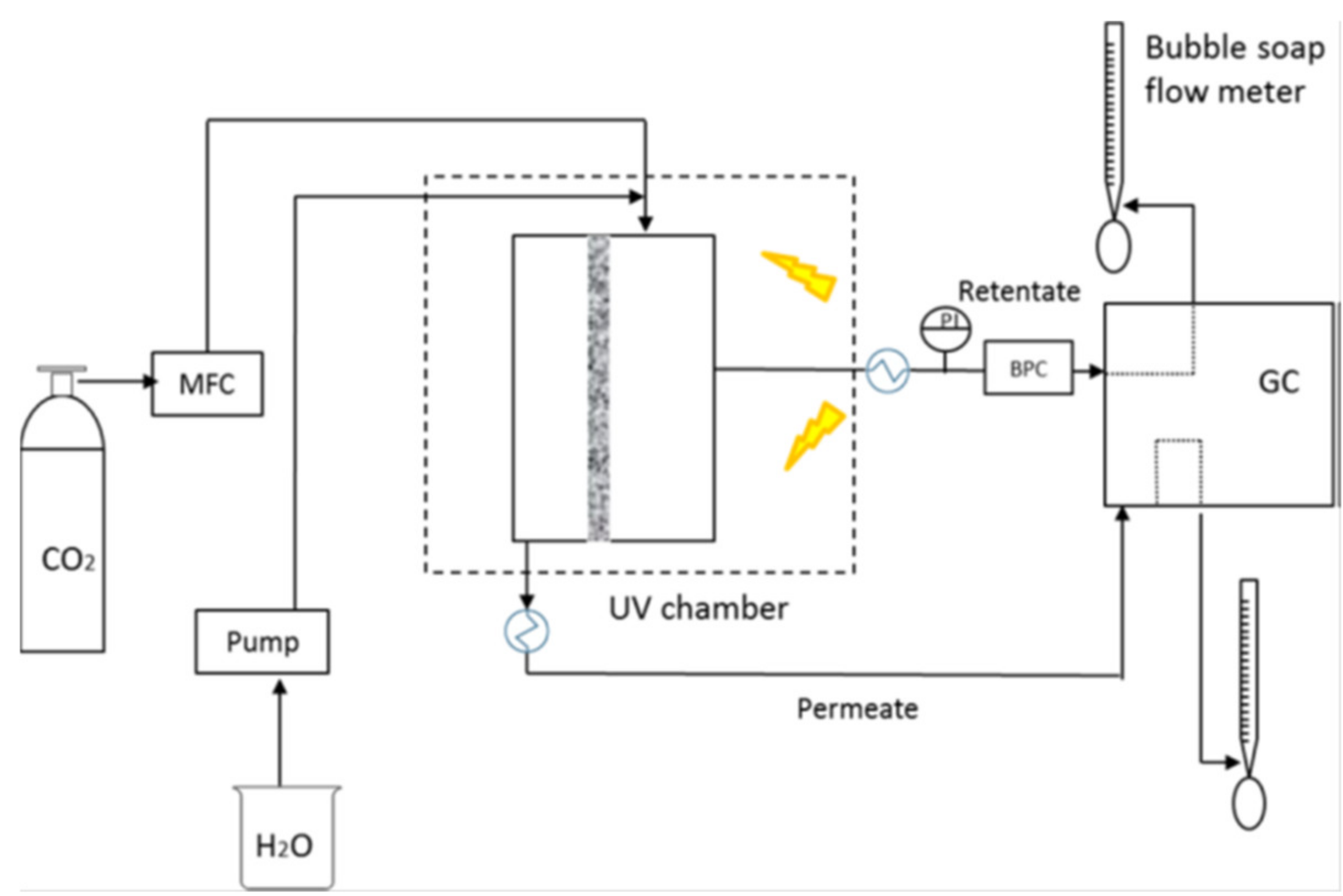
  75. Pomilla, F.R.; Brunetti, A.; Marcì, G.; Garcıá-Loṕez, E.I.; Fontananova, E.; Palmisano, L.; Barbieri, G. CO2 to Liquid Fuels: Photocatalytic Conversion in a Continuous Membrane Reactor. ACS Sustain. Chem. Eng. 2018, 6, 8743–8753. [Google Scholar] [CrossRef]
  76. Chen, C.-Y.; Yu, J.C.-C.; Nguyen, V.-H.; Wu, J.C.-S.; Wang, W.-H.; Kocí, K. Reactor Design for CO2 Photo-Hydrogenation toward Solar Fuels under Ambient Temperature and Pressure. Catalysts 2017, 7, 63. [Google Scholar] [CrossRef]
  77. Lunde, P.J.; Kester, F.L. Rates of methane formation from carbon dioxide and hydrogen over a ruthenium catalyst. J. Catal. 1973, 30, 423–429. [Google Scholar] [CrossRef]
  78. Thampi, K.R.; Kiwi, J.; Gratzel, M. Methanation and photo-methanation of carbon dioxide at room temperature and atmospheric pressure. Nature 1987, 327, 506–508. [Google Scholar] [CrossRef]
  79. Lin, W.; Han, H.; Frei, H. CO2 splitting by H2O to CO and O2 under UV light in TiMCM-41 silicate sieve. J. Phys. Chem. B 2004, 108, 18269–18273. [Google Scholar] [CrossRef]
  80. Qin, G.; Zhang, Y.; Ke, X.; Tong, X.; Sun, Z.; Liang, M.; Xue, S. Photocatalytic reduction of carbon dioxide to formic acid, formaldehyde, and methanol using dye-sensitized TiO2 film. Appl. Catal. B Environ. 2013, 129, 599–605. [Google Scholar] [CrossRef]
  81. Slamet, H.; Nasution, H.W.; Purnama, E.; Kosela, S.; Lazuardi, G. Photocatalytic reduction of CO2 on copper-doped titania catalysts prepared by improved-impregnation method. Catal. Commun. 2005, 6, 313–319. [Google Scholar] [CrossRef]
  82. Mele, G.; Annese, C.; De Riccardis, A.; Fusco, C.; Palmisano, L.; Vasapollo, G.; D’Accolti, L. Turning lipophilic phthalocyanines/TiO2 composites into efficient photocatalysts for the conversion of CO2 into formic acid under UV–vis light irradiation. Appl. Catal. A Chem 2014, 481, 169–172. [Google Scholar] [CrossRef]
  83. Ichikawa, S.; Doi, R. Hydrogen production from water and conversion of carbon dioxide to useful chemicals by room temperature photoelectrocatalysis. Catal. Today 1996, 27, 271–277. [Google Scholar] [CrossRef]
  84. Ola, O.; Maroto-Valer, M.M. Review of Material Design and Reactor Engineering on TiO2 Photocatalysis for CO2 Reduction. J. Photochem. Photobiol. C 2015, 24, 16–42. [Google Scholar] [CrossRef]
  85. Maina, J.W.; Schütz, J.A.; Grundy, L.; Des Ligneris, E.; Yi, Z.; Kong, L.; Pozo-Gonzalo, C.; Ionescu, M.; Dumée, L.F. Inorganic Nanoparticles/Metal Organic Framework Hybrid Membrane Reactors for Efficient Photocatalytic Conversion of CO2. ACS Appl. Mater. Interfaces 2017, 9, 35010–35017. [Google Scholar] [CrossRef] [PubMed]
  86. Maina, J.W.; Pozo-Gonzalo, C.; Kong, L.; Schutz, J.; Hill, M.; Dumee, L.F. Metal Organic Framework Based Catalysts for CO2 Conversion. Mater. Horiz. 2017, 4, 345–361. [Google Scholar] [CrossRef]
  87. Wang, D.; Huang, R.; Liu, W.; Sun, D.; Li, Z. Fe-Based Mofs for Photocatalytic CO2 reduction: Role of Coordination Unsaturated Sites and Dual Excitation Pathways. ACS Catal. 2014, 4, 4254–4260. [Google Scholar] [CrossRef]
  88. Zeng, L.; Guo, X.; He, C.; Duan, C. Metal−Organic Frameworks: Versatile Materials for Heterogeneous Photocatalysis. ACS Catal. 2016, 6, 7935–7947. [Google Scholar] [CrossRef]
  89. Li, Y.; Xu, H.; Ouyang, S.; Ye, J. Metal-Organic Frameworks for Photocatalysis. Phys. Chem. Chem. Phys. 2016, 18, 7563–7572. [Google Scholar] [CrossRef] [PubMed]
  90. Zhao, H.; Yang, X.; Xu, R.; Li, J.; Gao, S.; Cao, R. CdS/NH2-UiO-66 hybrid membrane reactors for the efficient photocatalytic conversion of CO2. J. Mater. Chem. A 2018, 6, 20152–20160. [Google Scholar] [CrossRef]
  91. Wang, K.; Li, Q.; Liu, B.; Cheng, B.; Ho, W.; Yu, J. Sulfur-Doped g-C3N4 with Enhanced Photocatalytic CO2-Reduction Performance. Appl. Catal. B Environ. 2015, 176, 44–52. [Google Scholar] [CrossRef]
  92. Mao, J.; Peng, T.; Zhang, X.; Li, K.; Ye, L.; Zan, L. Effect of Graphitic Carbon Nitride Microstructures on the Activity and Selectivity of Photocatalytic CO2 Reduction Under Visible Light. Catal. Sci. Technol. 2013, 3, 1253–1260. [Google Scholar] [CrossRef]
  93. Dong, G.; Zhang, L. Porous structure dependent photoreactivity of graphitic carbon nitride under visible light. J. Mater. Chem. 2012, 22, 1160–1166. [Google Scholar] [CrossRef]
  94. Liu, L.; Yue, M.; Lu, J.; Hu, J.; Liang, Y.; Cui, W. The Enrichment of Photo-Catalysis Via Self-Assembly Perylenetetracarboxylic Acid Diimide Polymer Nanostructures Incorporating TiO2 Nano-Particles. Appl. Surf. Sci. 2018, 456, 645–656. [Google Scholar] [CrossRef]
  95. Li, M.; Zhang, L.; Wu, M.; Du, Y.; Fan, X.; Wang, M.; Zhang, L.; Kong, Q.; Shi, J. Mesostructured CeO2/g-C3N4 nanocomposites: Remarkably Enhanced Photocatalytic Activity for CO2 Reduction by Mutual Component Activations. Nano Energy 2016, 19, 145–155. [Google Scholar] [CrossRef]
  96. Fu, J.; Zhu, B.; Jiang, C.; Cheng, B.; You, W.; Yu, J. Hierarchical Porous O-Doped g-C3N4 with Enhanced Photocatalytic CO2 Reduction Activity. Small 2017, 13, 1603938. [Google Scholar] [CrossRef] [PubMed]
  97. Qin, J.; Wang, S.; Ren, H.; Hou, Y.; Wang, X. Photocatalytic Reduction of CO2 by Graphitic Carbon Nitride Polymers Derived from Urea and Barbituric Acid. Appl. Catal. B Environ. 2015, 179, 1–8. [Google Scholar] [CrossRef]
  98. Xiao, J.; Han, Q.; Xie, Y.; Yang, J.; Su, Q.; Chen, Y.; Cao, H. Is C3N4 Chemically Stable toward Reactive Oxygen Species in Sunlight-Driven Water Treatment? Environ. Sci. Technol. 2017, 51, 13380–13387. [Google Scholar] [CrossRef] [PubMed]
  99. Pomilla, F.R.; Cortes, M.A.L.R.M.; Hamilton, J.W.J.; Molinari, R.; Barbieri, G.; Marcì, G.; Palmisano, L.; Sharma, P.K.; Brown, A.; Byrne, J.A. An Investigation into the Stability of Graphitic C3N4 as a Photocatalyst for CO2 Reduction. J. Phys. Chem. C 2018, 122, 28727–28738. [Google Scholar] [CrossRef]
  100. Liu, X.; Jian, X.; Yang, H.; Song, X.; Liang, Z. A photocatalytic graphene quantum dots–Cu2O/bipolar membrane as a separator for water splitting. New J. Chem. 2016, 40, 3075–3079. [Google Scholar] [CrossRef]
  101. Vargas-Barbosa, N.M.; Geise, G.M.; Hickner, M.A.; Mallouk, T.E. Assessing the utility of bipolar membranes for use in photoelectrochemical water-splitting cells. ChemSusChem 2014, 7, 3017–3020. [Google Scholar] [CrossRef] [PubMed]
  102. Readi, O.M.K.; Kuenen, H.J.; Zwijnenberg, H.J.; Nijmeijer, K. Novel membrane concept for internal pH control in electrodialysis of amino acids using a segmented bipolar membrane (sBPM). J. Membr. Sci. 2013, 443, 219–226. [Google Scholar] [CrossRef]
  103. Rajesh, A.M.; Kumar, M.; Shahi, V.K. Functionalized biopolymer based bipolar membrane with poly ethylene glycol interfacial layer for improved water splitting. J. Membr. Sci. 2011, 372, 249–257. [Google Scholar] [CrossRef]
  104. Atienzar, P.; Primo, A.; Lavorato, C.; Molinari, R.; García, H. Preparation of Graphene Quantum Dots from Pyrolyzed Alginate. Langmuir 2013, 29, 6141–6146. [Google Scholar] [CrossRef] [PubMed]
  105. Chiarello, G.L.; Forni, L.; Selli, E. Photocatalytic hydrogen production by liquid-and gas-phase reforming of CH3OH over flame-made TiO2 and Au/TiO2. Catal. Today 2009, 144, 69–74. [Google Scholar] [CrossRef]
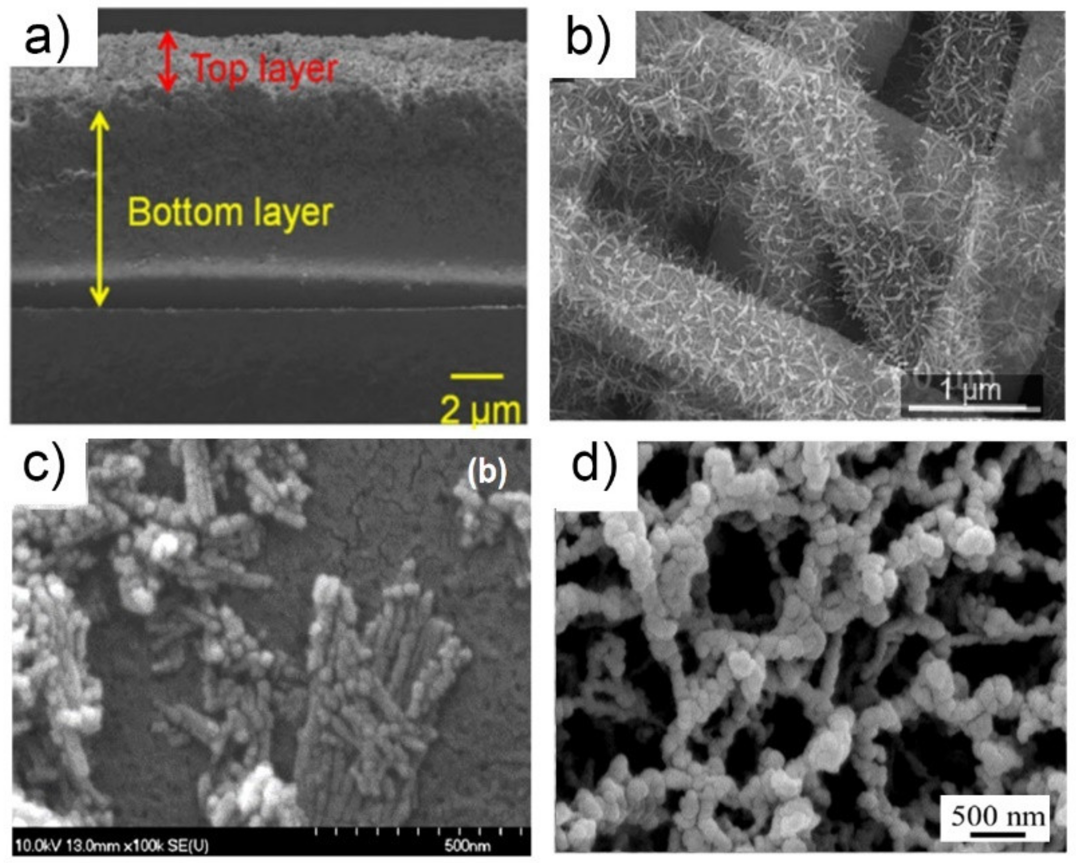
  106. Hattori, M.; Noda, K. All electrochemical fabrication of a bilayer membrane composed of nanotubular photocatalyst and palladium toward high-purity hydrogen production. Appl. Surf. Sci. 2015, 357, 214–220. [Google Scholar] [CrossRef]
  107. Su, C.-Y.; Wang, L.-C.; Liu, W.-S.; Wang, C.-C.; Perng, T.-P. Photocatalysis and Hydrogen Evolution of Al- and Zn-Doped TiO2 Nanotubes Fabricated by Atomic Layer Deposition. ACS Appl. Mater. Interfaces 2018, 10, 33287–33295. [Google Scholar] [CrossRef] [PubMed]
  108. Su, C.Y.; Wang, C.C.; Hsueh, Y.C.; Gurylev, V.; Kei, C.C.; Perng, T.P. Enabling High Solubility of ZnO in TiO2 by Nanolamination of Atomic Layer Deposition. Nanoscale 2015, 7, 19222–19230. [Google Scholar] [CrossRef] [PubMed]
  109. Su, C.Y.; Wang, C.C.; Hsueh, Y.C.; Gurylev, V.; Kei, C.C.; Perng, T.P. Fabrication of Highly Homogeneous Al-doped TiO2 Nanotubes by Nanolamination of Atomic Layer Deposition. J. Am. Ceram. Soc. 2017, 100, 4988–4993. [Google Scholar] [CrossRef]
  110. Lavorato, C.; Argurio, P.; Mastropietro, T.F.; Pirri, G.; Poerio, T.; Molinari, R. Pd/TiO2 doped faujasite photocatalysts for acetophenone transfer hydrogenation in a photocatalytic membrane reactor. J. Catal. 2017, 353, 152–161. [Google Scholar] [CrossRef]
  111. Li, J.; Yang, J.; Wen, F.; Li, C. A visible-light-driven transfer hydrogenation on CdS nanoparticles combined with iridium complexes. Chem. Commun. 2011, 47, 7080–7082. [Google Scholar] [CrossRef] [PubMed]
  112. Herrmann, J.M.; Duchamp, C.; Karkmaz, M.; Thu Hoai, B.; Lachheb, H.; Puzenat, E.; Guillard, C. Environmental green chemistry as defined by photocatalysis. J. Hazard. Mater. 2007, 146, 624–629. [Google Scholar] [CrossRef] [PubMed]
  113. Anpo, M. Utilization of TiO2 photocatalysts in green chemistry. Pure Appl. Chem. 2000, 72, 1265–1270. [Google Scholar] [CrossRef]
  114. Dubey, N.; Rayalu, S.S.; Labhsetwar, N.K.; Naidu, R.R.; Chatti, R.V.; Devotta, S. Photocatalytic properties of zeolite-based materials for the photoreduction of methyl orange. Appl. Catal. A Gen. 2006, 303, 152–157. [Google Scholar] [CrossRef]
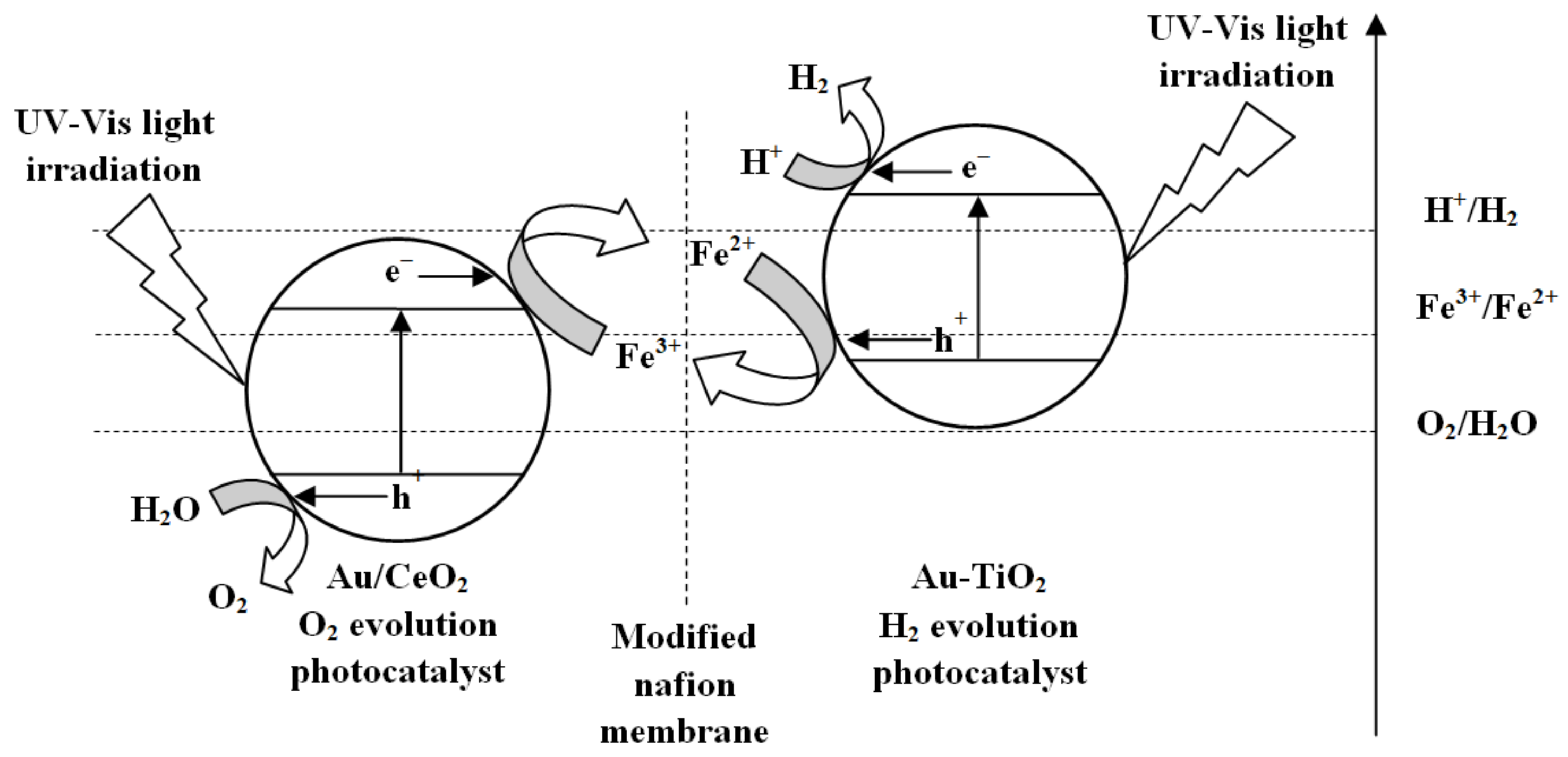
  115. Marino, T.; Figoli, A.; Molino, A.; Argurio, P.; Molinari, R. Hydrogen and Oxygen Evolution in a Membrane Photoreactor Using Suspended Nanosized Au/TiO2 and Au/CeO2. ChemEngineering 2019, 3, 5. [Google Scholar] [CrossRef]
  116. Zhao, X.; Zhang, Y.; Qiu, P.; Wen, P.; Wang, H.; Xu, G.; Han, Y. C-doped Cr2O3/NaY composite membrane supported on stainless steel mesh with enhanced photocatalytic activity for cyclohexane oxidation. J. Mater. Sci. 2018, 53, 6552–6561. [Google Scholar] [CrossRef]
  117. Xu, Y.; Schoonen, M.A.A. The absolute energy positions of conduction and valence bands of selected semiconducting minerals. Am. Mineral. 2000, 85, 543–556. [Google Scholar] [CrossRef]
  118. Shiraishi, Y.; Sugano, Y.; Ichikawa, S.; Hirai, T. Visible light-induced partial oxidation of cyclohexane on WO3 loaded with Pt nanoparticles. Catal. Sci. Technol. 2012, 2, 400–405. [Google Scholar] [CrossRef]
  119. Augugliaro, V.; Camera-Roda, G.; Loddo, V.; Palmisano, G.; Palmisano, L.; Parrino, F.; Puma, M.A. Synthesis of vanillin in water by TiO2 photocatalysis. Appl. Catal. B Environ. 2012, 111, 555–561. [Google Scholar] [CrossRef]
  120. Pickett-Baker, J.; Ozaki, R. Pro-Environmental Products: Marketing Influence on Consumer Purchase Decision. J. Consum. Mark. 2008, 25, 281–293. [Google Scholar] [CrossRef]
  121. Camera-Roda, G.; Augugliaro, V.; Cardillo, A.; Loddo, V.; Palmisano, G.; Palmisano, L. A pervaporation photocatalytic reactor for the green synthesis of vanillin. Chem. Eng. J. 2013, 224, 136–143. [Google Scholar] [CrossRef]
  122. Camera-Roda, G.; Santarelli, F.; Augugliaro, V.; Loddo, V.; Palmisano, G.; Palmisano, L.; Yurdakal, S. Photocatalytic process intensification by coupling with pervaporation. Catal. Today 2011, 161, 209–213. [Google Scholar] [CrossRef]
  123. Camera-Roda, G.; Santarelli, F. Design of a Pervaporation Photocatalytic Reactor for Process Intensification. Chem. Eng. Technol. 2012, 35, 1221–1228. [Google Scholar] [CrossRef]
  124. Böddeker, K.W.; Bengston, G.; Pingel, H.; Dozel, S. Pervaporation of high boilers using heated membranes. Desalination 1993, 90, 249–257. [Google Scholar] [CrossRef]
  125. Böddeker, K.W.; Gatfield, I.L.; Jähnig, J.; Schorm, C. Pervaporation at the vapor pressure limit: Vanillin. J. Membr. Sci. 1997, 137, 155–158. [Google Scholar] [CrossRef]
  126. Camera-Roda, G.; Augugliaro, V.; Loddo, V.; Palmisano, L. Pervaporation membrane reactors. In Handbook of Membrane Reactors: Reactor Types and Industrial Applications; Basile, A., Ed.; Woodhead Publishing Limited: Cambridge, UK, 2013; Volume 2, pp. 107–151. [Google Scholar]
  127. Brazhina, C.; Barbosa, B.; Crespo, G.J. Sustainable recovery of pure natural vanillin from fermentation media in a single pervaporation step. Green Chem. 2011, 13, 2197–2203. [Google Scholar] [CrossRef]
  128. Camera-Roda, G.; Augugliaro, V.; Loddo, V.; Palmisano, G.; Palmisano, L. Production of Aldehydes by Oxidation in Aqueous Medium with Recovery of the Product by Means of Pervaporation. U.S. Patent 20130123546A1, 10 June 2011. [Google Scholar]
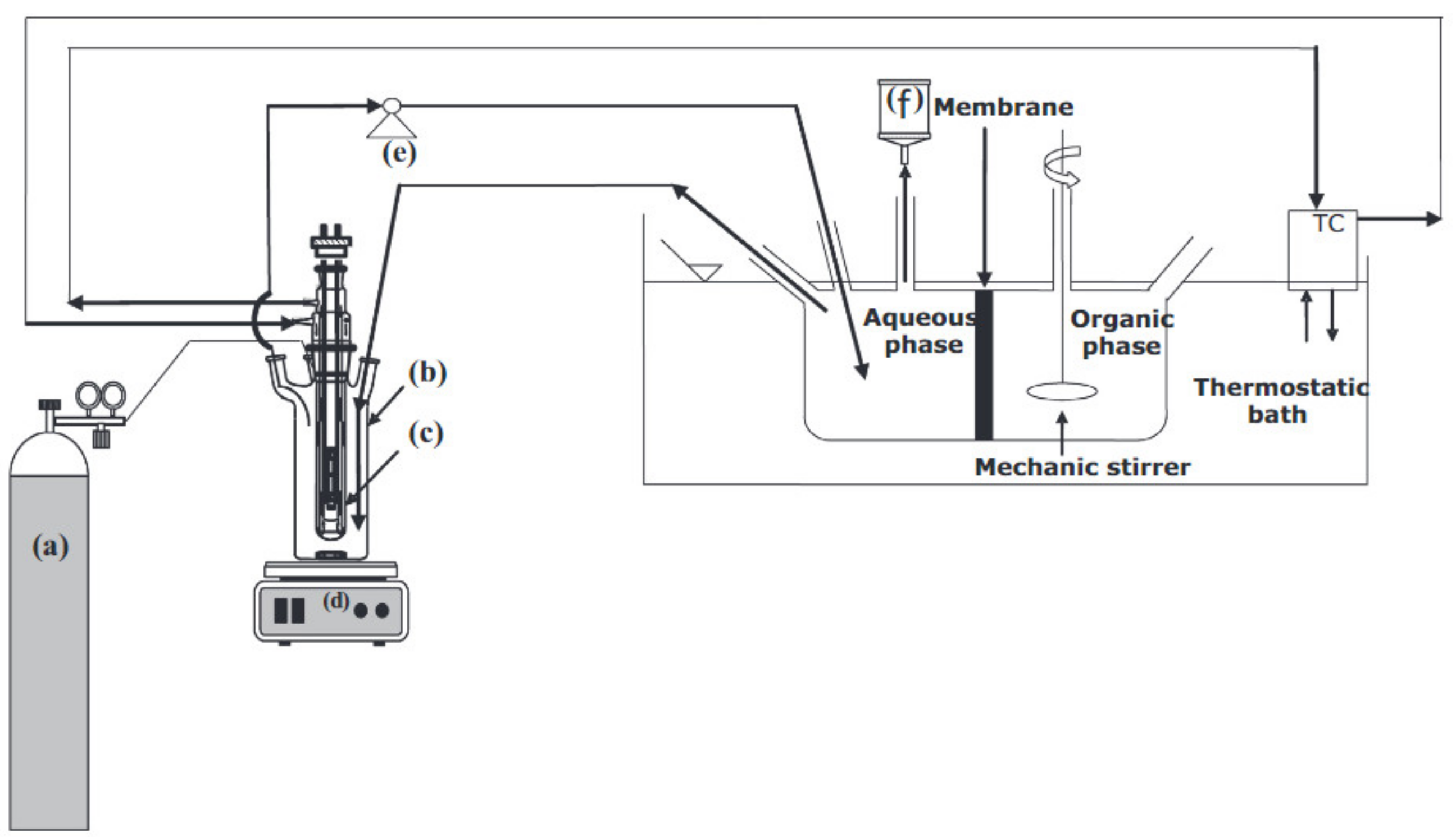
  129. Molinari, R.; Lavorato, C.; Poerio, T. Performance of vanadium based catalyst in a membrane contactor for the benzene hydroxylation to phenol. Appl. Catal. A Gen. 2012, 417, 87–92. [Google Scholar] [CrossRef]
  130. Liu, Y.; Murata, K.; Inaba, M. Direct oxidation of benzene to phenol by molecular oxygen over catalytic systems containing Pd(OAc)2 and heteropolyacid immobilized on HMS or PIM. J. Mol. Catal. A Chem. 2006, 256, 247–255. [Google Scholar] [CrossRef]
  131. Shimizu, K.; Akahane, H.; Kodama, T.; Kitayama, Y. Selective photo-oxidation of benzene over transition metal-exchanged BEA zeolite. Appl. Catal. A Gen. 2004, 269, 75–80. [Google Scholar] [CrossRef]
  132. Molinari, R.; Argurio, P.; Poerio, T. Vanadyl acetylacetonate filled PVDF membranes as the core of a liquid phase continuous process for pure phenol production from benzene. J. Membr. Sci. 2015, 476, 490–499. [Google Scholar] [CrossRef]
  133. Molinari, R.; Palmisano, L.; Loddo, V.; Mozia, S.; Morawski, A.W. Photocatalytic membrane reactors: Configurations, performance and applications in water treatment and chemical production. In Handbook of Membrane Reactors: Reactor Types and Industrial Applications; Basile, A., Ed.; Woodhead Publishing Limited: Cambridge, UK, 2013; Volume 2, pp. 808–845. [Google Scholar]
  134. Pastrana-Martínez, L.M.; Morales-Torres, S.; Figueiredo, J.L.; Faria, J.L.; Silva, A.M.T. Graphene oxide based ultrafiltration membranes for photocatalytic degradation of organic pollutants in salty water. Water Res. 2015, 77, 179–190. [Google Scholar] [CrossRef] [PubMed]
  135. Lv, Y.; Zhang, C.; He, A.; Yang, S.J.; Wu, G.P.; Darling, S.B.; Xu, Z.H. Photocatalytic Nanofiltration Membranes with Self-Cleaning Property for Wastewater Treatment. Adv. Funct. Mater. 2017, 27, 1700251. [Google Scholar] [CrossRef]
  136. Rodríguez-Chueca, J.; Mesones, S.; Marugán, J. Hybrid UV-C/microfiltration process in membrane photoreactorfor wastewater disinfection. Environ. Sci. Pollut. Res. 2018, 1–8. [Google Scholar] [CrossRef]
  137. Horovitz, I.; Avisar, D.; Luster, E.; Lozzi, L.; Luxbacher, T.; Mamane, H. MS2 bacteriophage inactivation using a N-doped TiO2-coated photocatalytic membrane reactor: Influence of water-quality parameters. Chem. Eng. J. 2018, 354, 995–1006. [Google Scholar] [CrossRef]
  138. Adán, C.; Marugán, J.; Mesones, S.; Casado, C.; van Grieken, R. Bacterial inactivation and degradation of organic molecules by titanium dioxide supported on porous stainless steel photocatalytic membranes. Chem. Eng. J. 2017, 318, 29–38. [Google Scholar] [CrossRef]
  139. Jiang, Y.; Liu, D.; Cho, M.; Lee, S.S.; Zhang, F.; Biswas, P.; Fortner, J.D. In Situ Photocatalytic Synthesis of Ag Nanoparticles (nAg) by Crumpled Graphene Oxide Composite Membranes for Filtration and Disinfection Applications. Environ. Sci. Technol. 2016, 50, 2514–2521. [Google Scholar] [CrossRef] [PubMed]
  140. Kazemi, M.; Jahanshahi, M.; Peyravi, M. Hexavalent chromium removal by multilayer membrane assisted by photocatalytic couple nanoparticle from both permeate and retentate. J. Hazard. Mater. 2018, 344, 12–22. [Google Scholar] [CrossRef] [PubMed]
  141. Wang, L.; Zhang, C.; Gao, F.; Mailhot, G.; Pan, G. Algae decorated TiO2/Ag hybrid nanofiber membrane with enhanced photocatalytic activity for Cr(VI) removal under visible light. Chem. Eng. J. 2017, 314, 622–630. [Google Scholar] [CrossRef]
  142. Roso, M.; Boaretti, C.; Bonora, R.; Modesti, M.; Lorenzetti, A. Nanostructured Active Media for Volatile Organic Compounds Abatement: The Synergy of Graphene Oxide and Semiconductor Coupling. Ind. Eng. Chem. Res. 2018, 57, 16635–16644. [Google Scholar] [CrossRef]
  143. Zhang, D.; Dai, F.; Zhang, P.; An, Z.; Zhao, Y.; Chen, L. The photodegradation of methylene blue in water with PVDF/GO/ZnO composite membrane. Mater. Sci. Eng. C 2019, 96, 684–692. [Google Scholar] [CrossRef] [PubMed]
  144. Wei, Y.; Zhu, Y.; Jiang, Y. Photocatalytic self-cleaning carbon nitride nanotube intercalated reduced graphene oxide membranes for enhanced water purification. Chem. Eng. J. 2019, 356, 915–925. [Google Scholar] [CrossRef]
  145. Sanches, S.; Nunes, C.; Passarinho, P.C.; Ferreira, F.C.; Pereira, V.J.; Crespo, J.G. Development of photocatalytic titanium dioxide membranes for degradation of recalcitrant compounds. Chem. Technol. Biotechnol. 2017, 92, 1727–1737. [Google Scholar] [CrossRef]
  146. Paredes, L.; Murgolo, S.; Dzinun, H.; Othman, M.H.D.; Ismail, A.F.; Carballa, M.; Mascolo, G. Application of immobilized TiO2 on PVDF dual layer hollow fibre membrane to improve the photocatalytic removal of pharmaceuticals in different water matrices. Appl. Catal. B Environ. 2019, 240, 9–18. [Google Scholar] [CrossRef]
  147. Guo, B.; Pasco, E.V.; Xagoraraki, I.; Tarabara, V.V. Virus removal and inactivation in a hybrid microfiltration-UV process with a photocatalytic membrane. Sep. Purif. Technol. 2015, 149, 245–254. [Google Scholar] [CrossRef]
  148. Song, L.; Zhu, B.; Jegatheesan, V.; Gray, S.; Duke, M.; Muthukumaran, S. Treatment of secondary effluent by sequential combination of photocatalytic oxidation with ceramic membrane filtration. Environ. Sci. Pollut. Res. 2018, 25, 5191–5202. [Google Scholar] [CrossRef] [PubMed]
  149. Abid, M.F.; Abdulrahman, A.A.; Hamza, N.H. Hydrodynamic and kinetic study of a hybrid detoxification process with zero liquid discharge system in an industrial wastewater treatment. J. Environ. Health Sci. Eng. 2014, 12, 145. [Google Scholar] [CrossRef] [PubMed]
  150. Yatmaz, H.C.; Dizge, N.; Kurt, M.S. Combination of photocatalytic and membrane distillation hybrid processes for reactive dyes treatment. Environ. Technol. 2017, 38, 2743–2751. [Google Scholar] [CrossRef] [PubMed]
  151. Patsios, S.I.; Sarasidis, V.C.; Karabelas, A.J. A hybrid photocatalysis-UF separation process for water purification: Humic acids and polysaccharides degradation. In Proceedings of the International Desalination Association World Congress on Desalination and Water Reuse, Tianjin, China, 20–25 October 2013. [Google Scholar]
  152. Khan, S.; Kim, J.; Sotto, A.; Van der Bruggen, B. Humic acid fouling in a submerged photocatalytic membrane reactor with binary TiO2–ZrO2 particles. J. Ind. Eng. Chem. 2015, 21, 779–786. [Google Scholar] [CrossRef]
  153. Darowna, D.; Wróbel, R.; Morawski, A.W.; Mozia, S. The influence of feed composition on fouling and stability of a polyethersulfone ultrafiltration membrane in a photocatalytic membrane reactor. Chem. Eng. J. 2017, 310, 360–367. [Google Scholar] [CrossRef]
  154. Fernández López, R.; McDonald, J.A.; Khan, S.J.; Le-Clech, P. Removal of pharmaceuticals and endocrine disrupting chemicals by a submerged membrane photocatalysis reactor (MPR). Sep. Purif. Technol. 2014, 127, 131–139. [Google Scholar] [CrossRef]
  155. Sarasidis, V.C.; Plakas, K.V.; Patsios, S.I.; Karabelas, A.J. Investigation of diclofenac degradation in a continuous photo-catalytic membrane reactor. Influence of operating parameters. Chem. Eng. J. 2014, 239, 299–311. [Google Scholar] [CrossRef]
  156. Plakas, K.V.; Sarasidis, V.C.; Patsios, S.I.; Lambropoulou, D.A.; Karabelas, A.J. Novel pilot scale continuous photocatalytic membrane reactor for removal of organic micropollutants from water. Chem. Eng. J. 2016, 304, 335–343. [Google Scholar] [CrossRef]
  157. Espíndola, J.C.; Szymański, K.; Cristóvã, R.O.; Mendes, A.; Vilar, V.J.P.; Mozia, S. Performance of hybrid systems coupling advanced oxidation processes and ultrafiltration for oxytetracycline removal. Catal. Today 2018. [Google Scholar] [CrossRef]
  158. Vatanpour, V.; Karami, A.; Sheydaei, M. Improved visible photocatalytic activity of TiO2 nanoparticles to use in submerged membrane photoreactor for organic pollutant degradation. Int. J. Environ. Sci. Technol. 2018, 1–10. [Google Scholar] [CrossRef]
  159. Laohaprapanon, S.; Matahum, J.; Tayo, L.; You, S.-J. Photodegradation of Reactive Black 5 in a ZnO/UV slurry membrane reactor. J. Taiwan Inst. Chem. Eng. 2015, 49, 136–141. [Google Scholar] [CrossRef]
  160. Shi, Z.; Wang, X.; Peng, T. Removal of methylene blue using photocatalytic slurry reactor coupled with ceramic membrane cross-flow filtration process. Mater. Res. Innov. 2014, 18, 191–195. [Google Scholar] [CrossRef]
  161. O’Neal Stancl, H.; Hristovski, K.; Westerhoff, P. Hexavalent Chromium Removal Using UV-TiO2/Ceramic Membrane Reactor. Environ. Eng. Sci. 2015, 32, 676–683. [Google Scholar] [CrossRef]
  162. Doruk, N.; Yatmaz, H.C.; Dizge, N. Degradation Efficiency of Textile and Wood Processing Industry Wastewater by Photocatalytic Process Using In Situ Ultrafiltration Membrane. CSAWAC 2016, 44, 219–324. [Google Scholar] [CrossRef]
  163. Deveci, E.Ü.; Dizge, N.; Yatmaz, H.C.; Aytepe, Y. Integrated process of fungal membrane bioreactor and photocatalytic membrane reactor for the treatment of industrial textile wastewater. Biochem. Eng. J. 2016, 105, 420–427. [Google Scholar] [CrossRef]
  164. Mozia, S.; Darowna, D.; Szymański, K.; Grondzewska, S.; Borchert, K.; Wróbel, R.; Morawski, A.W. Performance of two photocatalytic membrane reactors for treatment of primary and secondary effluents. Catal. Today 2014, 236A, 135–145. [Google Scholar] [CrossRef]
  165. Szymański, K.; Morawski, A.W.; Mozia, S. Effectiveness of treatment of secondary effluent from a municipal wastewater treatment plant in a photocatalytic membrane reactor and hybrid UV/H2O2—Ultrafiltration system. Chem. Eng. Process 2018, 125, 318–324. [Google Scholar] [CrossRef]
  166. Darowna, D.; Grondzewska, S.; Morawski, A.W.; Mozia, S. Removal of non-steroidal anti-inflammatory drugs from primary and secondary effluents in a photocatalytic membrane reactor. J. Chem. Technol. Biotechnol. 2014, 89, 1265–1273. [Google Scholar] [CrossRef]
  167. Szymański, K.; Morawski, A.W.; Mozia, S. Surface water treatment in hybrid systems coupling advanced oxidation processes and ultrafiltration using ceramic membrane. Desalin. Water Treat. 2017, 64, 302–306. [Google Scholar] [CrossRef]
  168. Ong, C.S.; Lau, W.J.; Goh, P.S.; Ng, B.C.; Ismail, A.F. Investigation of submerged membrane photocatalytic reactor (sMPR) operating parameters during oily wastewater treatment process. Desalination 2014, 353, 48–56. [Google Scholar] [CrossRef]
  169. Jiang, L.; Zhang, X.; Choo, K.H. Submerged microfiltration-catalysis hybrid reactor treatment: Photocatalytic inactivation of bacteria in secondary wastewater effluent. Sep. Purif. Technol. 2018, 198, 87–92. [Google Scholar] [CrossRef]
  170. Wang, J.; Sun, X.; Yuan, Y.; Chen, H.; Wang, H.; Hou, D. A novel microwave assisted photo-catalytic membrane distillation process for treating the organic wastewater containing inorganic ions. J. Water Process Eng. 2016, 9, 1–8. [Google Scholar] [CrossRef]
  171. Meng, X.; Zhang, Z. Bismuth-based photocatalytic semiconductors: Introduction, challenges and possible approaches. J. Mol. Catal. A Chem. 2016, 423, 533–549. [Google Scholar] [CrossRef]
Figure 1. SEM images of PMs prepared by (a) dip-coating [65]; (b) electrospinning—hydrothermal synthesis [68]; (c) physical deposition [69]; (d) chemical vapor deposition [58].
Catalysts 09 00239 g001
Figure 2. Scheme of photocatalytic membrane reactor setup [75].
Catalysts 09 00239 g002
Figure 3. Scheme of the membrane contactor integrated with the batch photoreactor: (a) argon cylinder; (b) photoreactor; (c) medium pressure Hg lamp with cooling jacket; (d) magnetic stirrer; (e) peristaltic pump; (f) degassing system; (TC) temperature controller [110].
Catalysts 09 00239 g003
Figure 4. Diagram of the Z-scheme overall water splitting using Au/CeO2 as a photocatalyst for oxygen generation, Au/TiO2 for hydrogen generation, and Fe3+/Fe2+ as a redox couple [115].
Catalysts 09 00239 g004
Figure 5. Scheme of the photocatalysis-pervaporation set-up [40].
Catalysts 09 00239 g005
Figure 6. Schematic diagram of PMR utilizing a PM with the photoactive support layer [53].
Catalysts 09 00239 g006
Figure 7. PMR equipped with a polymer membrane with photocatalytically active separation layer [134].
Catalysts 09 00239 g007
Figure 8. Schematic diagram of a submerged PMR for diclofenac removal from water [155].
Catalysts 09 00239 g008
Figure 9. Oscillatory PMR for pharmaceuticals removal from water [50].
Catalysts 09 00239 g009
Figure 10. Schematic diagram of the PMR coupled with RO filtration for removal of textile and wood processing industry wastewater. [162].
Catalysts 09 00239 g010
Figure 11. Schematic diagram of the PMR coupled with NF for removal of Congo Red. [32].
Catalysts 09 00239 g011
Figure 12. Schematic diagram of combined photocatalysis/low pressure reverse osmosis (LPRO) system to methyl violet dye removal [149].
Catalysts 09 00239 g012
Figure 13. Schematic diagram of the laboratory scale PMR with ceramic membranes used for HA removal from water [46].
Catalysts 09 00239 g013
Figure 14. Schematic diagram of PMR utilizing microwave assisted photocatalysis and vacuum membrane distillation for wastewater treatment [170].
Catalysts 09 00239 g014
Table 1. The influence of various operation parameters on PMRs performance.
Operation FactorsEffectsRef.
Type of membrane processPMRs utilizing pressure driven membrane processes are more prone to fouling than systems with other driving forces (e.g., pervaporation, membrane distillation, dialysis).[24]
Operating modePMRs utilizing pressure driven membrane techniques:
(a)
pressurized—tendency for membrane fouling caused by photocatalyst particles;
(b)
depressurized—less prone to fouling caused by photocatalyst particles.
[47]
[45]
Operating conditions Aeration: improvement of the process performance (fouling mitigation; increase of photodecomposition efficiency); however, at high aeration rates the bubble cloud can attenuate the UV/VIS light transmission in the photoreactor.[45]
Back-flushing: alleviation of membrane fouling caused by photocatalyst particles or in case of membranes with large pores no positive results.[48]
[47]
Cross flow velocity (CFV): enhancement of membrane performance with increasing CFV as a result of higher shear rates prevents the deposition of photocatalyst cake layer.[49]
Transmembrane pressure (pressure driven membrane techniques):
(a)
Increase of transmembrane pressure (TMP) enhances deposition of photocatalyst particles on a membrane surface and leads to formation of a dense filtration cake;
(b)
Working below the critical flux value can prevent from the deposition of the filtration cake layer on the membrane surface.
[49]
[47]
PhotocatalystUnder unfavorable process conditions, membrane fouling due to the presence of photocatalyst particles, especially in case of pressurized systems.[47]
Fouling mitigation due to decomposition of organic contaminants in case of both PMs and slurry PMRs.[50]
Higher photocatalyst loading can cause increase of permeate flux; however, at too high concentration the screening effect may attenuate the UV/VIS radiation transmission in the photoreactor.[50]
Feed compositionChemical nature of contaminants strictly affects their adsorption on photocatalyst particles thus influencing their removal efficiency and fouling severity.[33]
[46]
Less severe membrane fouling at neutral and acidic pH compared to alkaline conditions.
Table 2. Selected examples of application of PMs in removal of organic contaminants from water.
PollutantMembraneParametersPhotodegradation EfficiencyRef.
Methylene blueatomic-layer-deposited carbon nanotube ZnO-TiO2;C0 = 20 mg L−1, UV irradiation94% in 100 min[57]
hydrophobic CeO2 coated stainless steel membrane;C0 = 10 mg L−1 in oil-water mixture, UV irradiation>99% in 80 min[64]
PVDF/GO/ZnO nanocomposites membraneC0 = 10 mg L−1, xenon light irradiation86.84% in 100 min[143]
Rhodamine Bg-C3N4 NT/rGO NF membraneC0 = 10 mg L−1, VIS irradiation>98% in 300 min[144]
Eosin yellowPSF/N,Pd co-doped TiO2 composite membraneC0 = 100 mg L−1, VIS irradiation>97% in 4 h[30]
IbuprofenCu2O modified PSF UF membraneC0 = 10 mg L−1, VIS irradiationup to 86%[59]
DiclofenacZnO and TiO2 sputtered membranesC0 = 9.3×10⁻⁵ M, UV irradiationalmost complete in 6 h[58]
CarbamazepineN-doped TiO2 coated PMC0 = 1 g L−1, UV and VIS light90% higher reaction rate [53]
TetracyclineZnIn2S4 coated PVDF membraneC0 = 100 µg L−1, VIS irradiation 92% in 36 h[61]
PhenolPES/O-g-C3N4 hybrid membraneC0 = 10 mg L−1, UV and VIS irradiation35.8% in 300 min[66]
Humic acidsTiO2 nanowires/Fe2O3 nanoparticles/GO sheets membrane;C0 = 25 mg L−1, solar radiation92% in 12 h[60]
ceramic membranes coated with TiO2C0 = 0.2 g L−1, UV irradiation98.56% removal[65]
Diuron Chlorfenvinphosmagnetron sputtered TiO2 on ceramic membraneC0 = 1 mg L−1,75% in 3 h[145]
solar radiation78% in 3 h

