Acetylene Abatement Over Micro/Mesoporous Active Carbon-Supported Low-Mercury Catalysts


Abstract
:
1. Introduction
2. Results and Discussion
2.1. Physicochemical Characterizations
2.1.1. BET
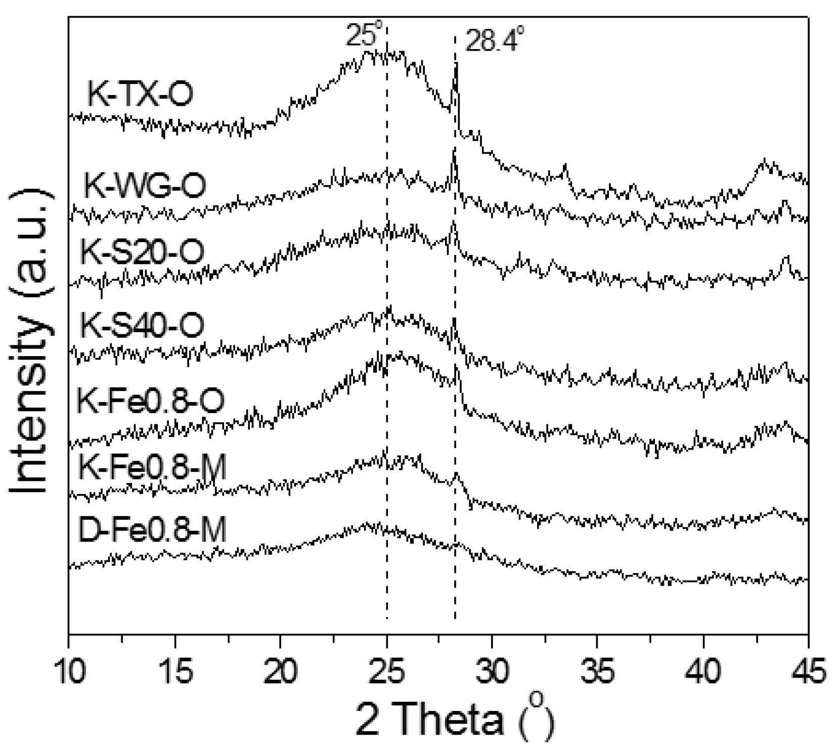
2.1.2. XRD
2.1.3. SEM and Back Scattered Electron (BSE)
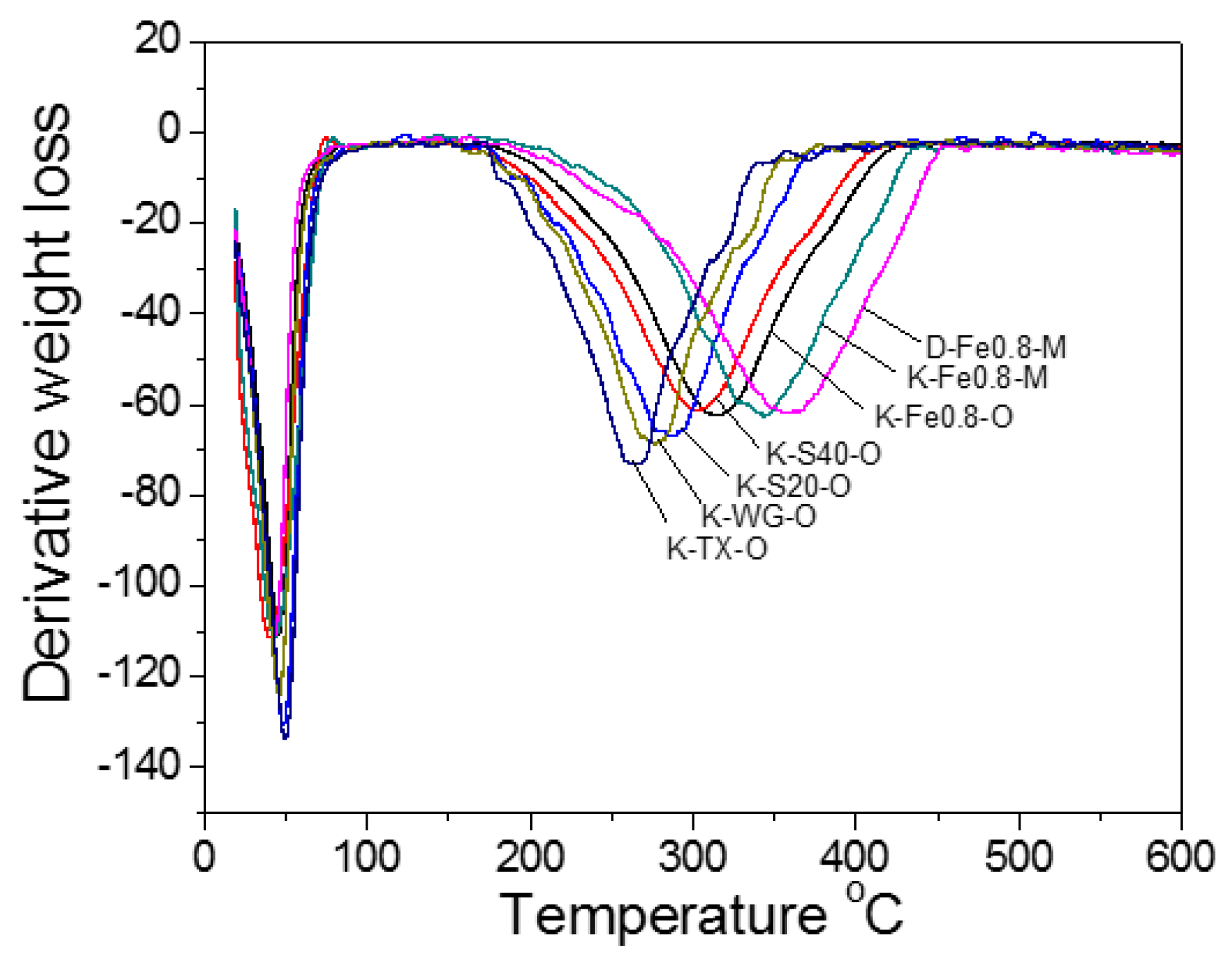
2.1.4. TG
2.2. Activity Measurement
2.2.1. Activity Test
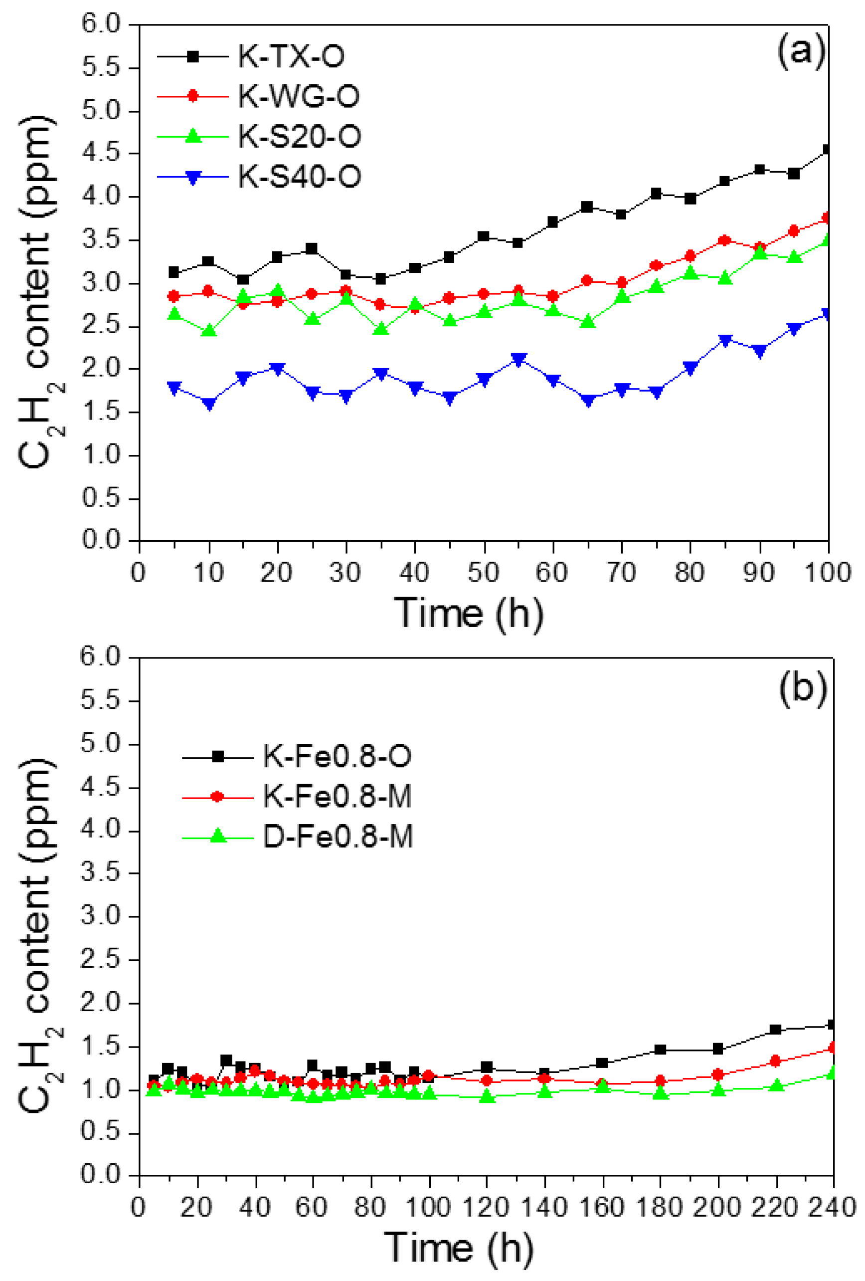
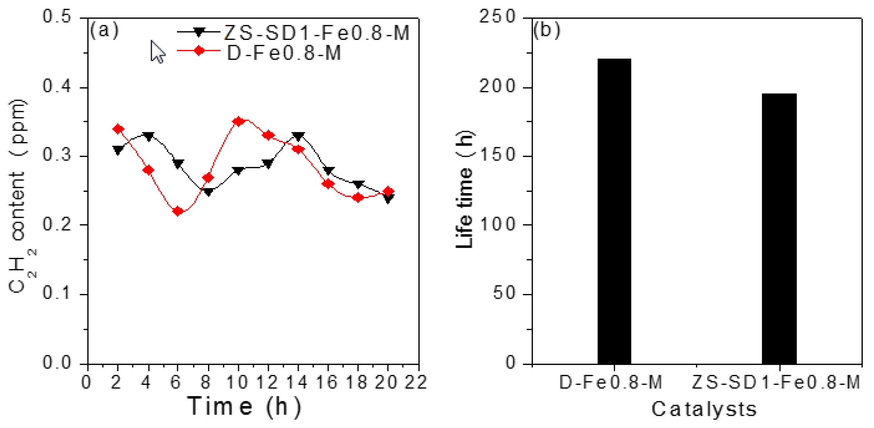
2.2.2. Long-Term Reaction Stability Test
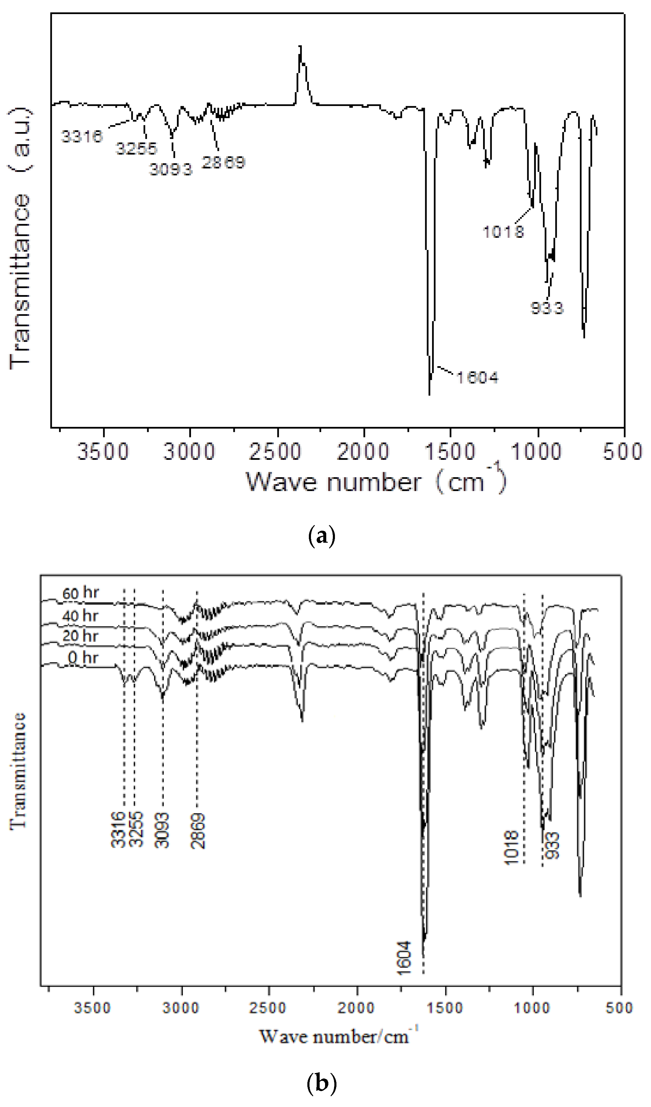
2.2.3. Deactivation and Reactivation of the D-Fe0.8-M
2.3. Correlation between Physicochemical Property and Activity Performance
3. Experimental
3.1. Catalyst Preparation
3.1.1. AC Substrate Preparation
3.1.2. Low-mercury AC-Supported Catalysts Preparation
3.2. Catalyst Characterization
3.3. Activity Test
4. Conclusions
Supplementary Materials
Author Contributions
Funding
Conflicts of Interest
References
- Wolfgang, A. Future semiconductor material requirements and innovations as projected in the ITRS 2005 roadmap. Mater. Sci. Eng. B 2006, 134, 104–108. [Google Scholar]
- Hitoshi, H.; Yasuaki, A.; Shoji, A.; Toru, O.; Wei, F.Q.; Manabu, S.; Kikuo, O. Chemical process of silicon epitaxial growth in a SiHCl3-H2 system. J. Cryst. Growth 1999, 207, 77–86. [Google Scholar]
- Tanimoto, Y. Hydrogen Chloride Manufacturing Method. CN Patent 107848799A, 27 March 2018. [Google Scholar]
- Tanimoto, Y. Hydrogen Chloride Manufacturing Method. CN Patent 107848798A, 27 March 2018. [Google Scholar]
- Zhang, J.R. Method and System for Preparing Hydrogen Chloride Gas with Moisture Content below 10 × 10−6. CN Patent 102838087A, 26 December 2012. [Google Scholar]
- Zhang, J.R. Method and System for Preparing Anhydrous Hydrogen Chloride Gas. CN Patent 101774543A, 14 July 2010. [Google Scholar]
- Zhang, J.R.; Song, W.M. Method for Preparing Electronic Grade Hydrogen Chloride. CN Patent 1511780, 14 July 2004. [Google Scholar]
- Severin, P.J.; Poodt, G.J. Capacitance-Voltage Measurements with a Mercury-Silicon Diode. J. Electrochem. Soc. 1972, 119, 1384–1388. [Google Scholar] [CrossRef]
- Lima, F.G.D.C.; Mescheder, U.; Katona, G.; Leiste, H.; Özel, E.; Müller, C. Influence of silicon doping type on the adhesion of seedless electrodeposited copper layers. Surf. Coat. Technol. 2018, 349, 208–216. [Google Scholar] [CrossRef]
- Tsai, C.C.; Jan, H.R.; Huang, C.H. Influence of surfactant addition for the texture etching process on multi-crystalline silicon wafer. J. Chin. Inst. Eng. 2012, 35, 69–77. [Google Scholar] [CrossRef]
- Dai, B.; Chen, K.; Wang, Y.; Kang, L.; Zhu, M. Boron and nitrogen doping in graphene for the catalysis of acetylene hydrochlorination. ACS Catal. 2015, 5, 2541–2547. [Google Scholar] [CrossRef]
- Li, P.; Li, H.; Pan, X.; Kai, T.; Cui, T.T.; Ding, M.Z.; Bao, X.H. Catalytically active boron nitride in acetylene hydrochlorination. ACS Catal. 2017, 7, 8572–8577. [Google Scholar] [CrossRef]
- Lin, R.; Kaiser, S.K.; Hauert, R.; Perezramirez, J. Descriptors for high-performance nitrogen-doped carbon catalysts in acetylene hydrochlorination. ACS Catal. 2018, 8, 1114–1121. [Google Scholar] [CrossRef]
- Zhi, L.; Li, Y.; Tang, H.; Liu, H.; Pei, W. Deactivation mechanism of low-mercury catalyst for acetylene hydrochlorination. Chem. React. Eng. Technol. 2015, 31, 343–353. [Google Scholar]
- Xu, X.L.; He, H.H.; Zhao, J.; Wang, B.L.; Gu, S.C.; Li, X.N. The ligand coordination approach for improving the stability of low-mercury catalyst in the hydrochlorination of acetylene. Chin. J. Chem. Eng. 2017, 25, 1217–1221. [Google Scholar] [CrossRef]
- Hutchings, G.J.; Haruta, M. A golden age of catalysis: A perspective. Appl. Catal. A 2005, 291, 2–5. [Google Scholar] [CrossRef]
- Mitchenko, S.A.; Krasnyakova, T.V.; Mitchenko, R.S.; Korduban, A.N. Acetylene catalytic hydrochlorination over powder catalyst prepared by pre-milling of K2PtCl4 salt. J. Mol. Catal. A Chem. 2007, 275, 101–108. [Google Scholar] [CrossRef]
- Hutchings, G.J. Gole catalysis in chemical processing. Catal. Today 2002, 72, 11–17. [Google Scholar] [CrossRef]
- Oliver-Meseguer, J.; Domenech-Carbo, A.; Boronat, M.; Leyva-Perez, A.; Corma, A. Partial reduction and selective transfer of hydrogen chloride on catalytic gold nanoparticles. Angew. Chem. Int. Ed. 2017, 56, 6435–6439. [Google Scholar] [CrossRef]
- Zhu, M.; Wang, Q.; Chen, K.; Wang, Y.; Huang, C.; Dai, H.; Yu, F.; Kang, L.; Dai, B. Development of a heterogeneous non-mercury catalyst for acetylene hydrochlorination. ACS Catal. 2015, 5, 5306–5316. [Google Scholar] [CrossRef]
- Conte, M.; Davies, C.J.; Morgan, D.J.; Davies, T.E.; Elias, D.J.; Carley, A.F.; Johnston, P.; Hutchings, G.J. Aqua regia activated Au/C catalysts for the hydrochlorination of acetylene. J. Catal. 2013, 297, 128–136. [Google Scholar] [CrossRef] [Green Version]
- Zhou, K.; Jia, J.; Li, C.; Xu, H.; Zhou, J.; Luo, G.H.; Wei, F. Low content Au-based catalyst for hydrochlorination of C2H2 and its industrial scale-up for future PVC process. Green Chem. 2014, 17, 356–364. [Google Scholar] [CrossRef]
- Wang, Y.J.; Tian, Y.; Zang, W.C.; Jian, X.D. Study on treatment and recycling of mercury from waste mercury catalysts in China. Procedia Environ. Sci. 2016, 31, 432–439. [Google Scholar] [CrossRef]
- Chen, M.; Kui, X.; Liao, J.; Chen, X. Effects of Cd cocatalytic mechanism in maltielement catalytic system on performance of low-level mercury catalysts. Polyvinyl Chloride 2014, 42, 26–29. [Google Scholar]
- Xu, X.L.; Zhao, J.; Lu, C.S.; Zhang, T.T.; Di, X.X.; Gu, S.C.; Li, X.N. Improvement of the stability of Hg/AC catalysts by CsCl for the high-temperature hydrochlorination of acetylene. Chin. Chem. Lett. 2016, 27, 822–826. [Google Scholar] [CrossRef]
- Zhou, Y.; Yang, Q.; Luo, Q.; Jiang, W.W. Preparation and optimization of a new-type low-mercury catalyst for hydrochlorination of acetylene. Appl. Chem. Ind. 2011, 40, 2147. [Google Scholar]
- Dong, X.B.; Chao, S.L.; Wan, F.F.; Guan, Q.X.; Wang, G.C.; Li, W. Sulfur and nitrogen co-doped mesoporous carbon with enhanced performance for acetylene hydrochlorination. J. Catal. 2018, 359, 161–170. [Google Scholar] [CrossRef]
- Liu, Z.; Ling, L.; Qiao, W.; Lu, C.; Dong, W.; Lang, L. Effects of various metals and their loading methods on the mesopore formation in pitch-based spherical activated carbon. Carbon 1999, 37, 1333–1335. [Google Scholar] [CrossRef]
- Liu, Z.; Ling, L.; Qiao, W.; Liu, L. Preparation of pitch-based spherical activated carbon with developed mesopore by the aid of ferrocene. Carbon 1999, 37, 663–667. [Google Scholar] [CrossRef]
- Lowell, S.; Shields, J.E.; Thomas, M.A.; Thommes, M. Characterization of Porous Solids and Powders: Surface Area, Pore Size and Density; Springer: Dordrecht, The Netherlands, 2005; Volume 16, p. 1620. [Google Scholar]
- Zhu, X.; Yu, S.; Xu, K.; Zhang, Y.; Zhang, L.; Lou, G. Sustainable activated carbons from dead ginkgo leaves for supercapacitor electrode active materials. Chem. Eng. Sci. 2018, 181, 36–45. [Google Scholar] [CrossRef]
- Wade, C.B.; Thurman, C.; Freas, W.; Student, J.; Matty, D.; Mohantya, D.K. Preparation and characterization of high efficiency modified activated carbon for the capture of mercury from flue gas in coal-fired power plants. Fuel Process. Technol. 2012, 97, 107–117. [Google Scholar] [CrossRef]
- Xie, Y.C.; Yang, N.F.; Liu, Y.J.; Tang, Y.Q. Spontaneous dispersion of some active components onto the surfaces of carriers. Sci. China Ser. B 1983, 26, 337–350. [Google Scholar]
- Jiang, L.; Chen, B.H.; Zhang, J.R.; Fu, J.Q. Effect of activated carbon pore size distribution on low-mercury catalyst performance for acetylene hydrochlorination. J. Chem. Ind. Eng. 2018, 69, 423–428. [Google Scholar]
- Wood, J.; Alldrick, M.J.; Winterbottom, J.M. Diffuse reflectance infrared Fourier transform spectroscopy (DRIFTS) study of ethyne hydrogenation on Pd/Al2O3. Catal. Today 2007, 128, 52–62. [Google Scholar] [CrossRef]
- Wei, H.; William, P.; Raul, F.L. Selective hydrogenation of acetylene in the presence of ethylene on K+-β-zeolite supported Pd and Pd/Ag catalysts. J. Catal. 2007, 246, 40–51. [Google Scholar]


| Samples | a SBET/m2 g−1 | b Vtotal/cm3 g−1 | c Vmicro/cm3 g−1 | d Vmeso/cm3 g−1 | Vmeso (Vtotal)−1/% | e D/nm |
|---|---|---|---|---|---|---|
| K-TX-O | 1545 | 0.81 | 0.58 | 0.23 | 28.3 | 1.16 |
| K-WG-O | 2137 | 1.31 | 0.97 | 0.35 | 26.3 | 0.96 |
| K-S20-O | 1619 | 0.78 | 0.40 | 0.38 | 49.1 | 2.01 |
| K-S40-O | 1943 | 1.18 | 0.44 | 0.74 | 62.8 | 4.34 |
| K-Fe0.8-O | 2019 | 1.34 | 0.40 | 0.94 | 70.3 | 5.21 |
| K-Fe0.8-M | 1802 | 1.17 | 0.26 | 0.91 | 77.6 | 5.45 |
| D-Fe0.8-M | 1723 | 1.03 | 0.25 | 0.78 | 75.5 | 5.12 |
| SD1-Fe0.8-M | 1215 | 0.71 | 0.11 | 0.60 | 84.8 | 6.36 |
| ZS-SD1-Fe0.8-M | 1498 | 0.82 | 0.116 | 0.704 | 85.8 | 7.11 |
© 2018 by the authors. Licensee MDPI, Basel, Switzerland. This article is an open access article distributed under the terms and conditions of the Creative Commons Attribution (CC BY) license (http://creativecommons.org/licenses/by/4.0/).
Share and Cite
Jiang, L.; Liu, N.; Dai, C.; Xu, R.; Chen, B.; Zhang, J. Acetylene Abatement Over Micro/Mesoporous Active Carbon-Supported Low-Mercury Catalysts. Catalysts 2018, 8, 610. https://doi.org/10.3390/catal8120610
Jiang L, Liu N, Dai C, Xu R, Chen B, Zhang J. Acetylene Abatement Over Micro/Mesoporous Active Carbon-Supported Low-Mercury Catalysts. Catalysts. 2018; 8(12):610. https://doi.org/10.3390/catal8120610
Chicago/Turabian StyleJiang, Luo, Ning Liu, Chengna Dai, Ruinian Xu, Biaohua Chen, and Jirui Zhang. 2018. "Acetylene Abatement Over Micro/Mesoporous Active Carbon-Supported Low-Mercury Catalysts" Catalysts 8, no. 12: 610. https://doi.org/10.3390/catal8120610