Gold/Iron Carbonyl Clusters for Tailored Au/FeOx Supported Catalysts


Abstract
:
1. Introduction
2. Results and Discussion
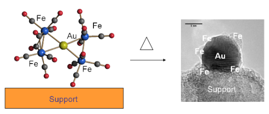
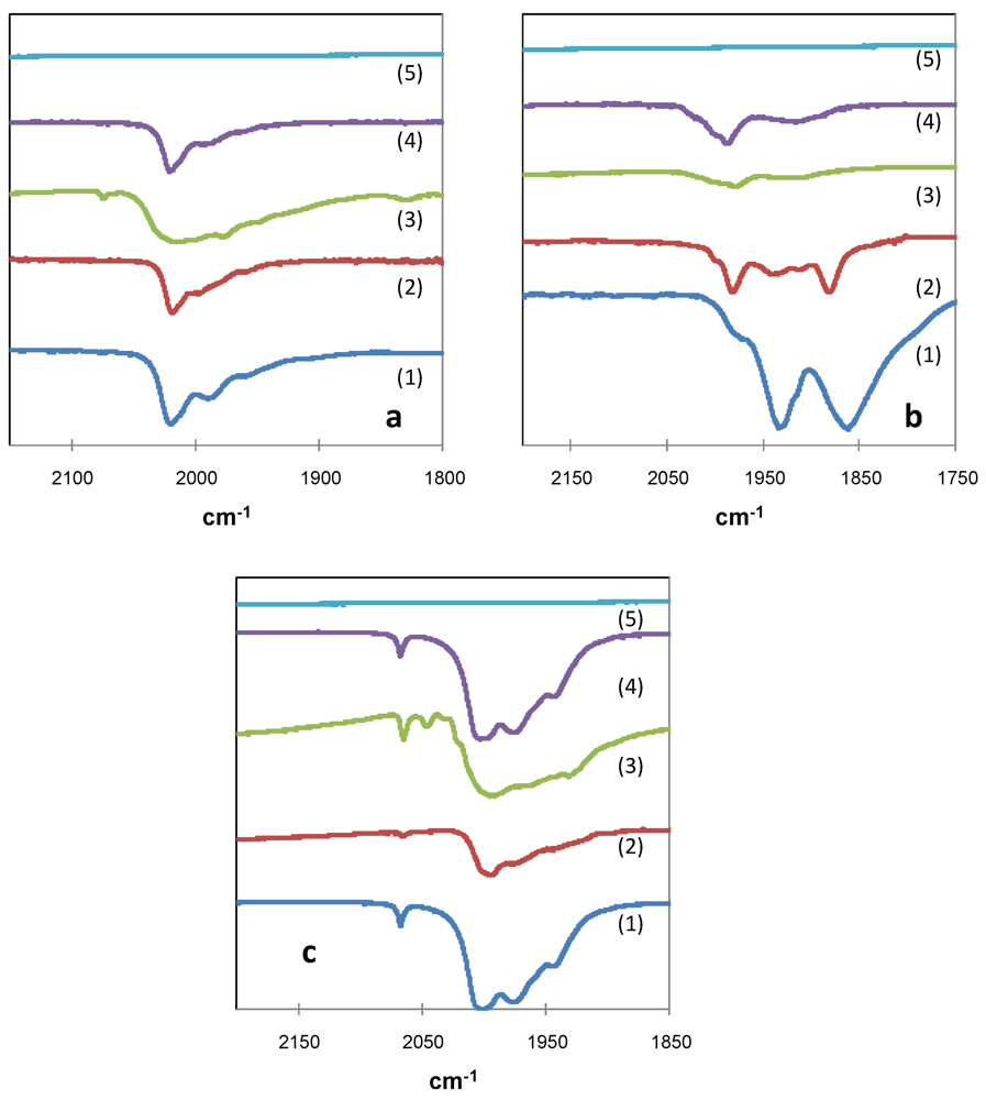
2.1. Interaction of Carbonyl Clusters with Different Supports


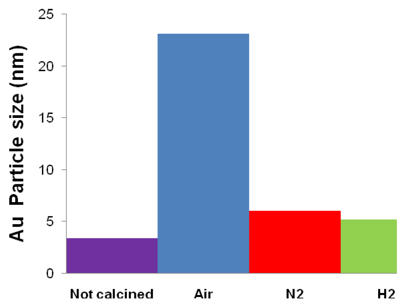
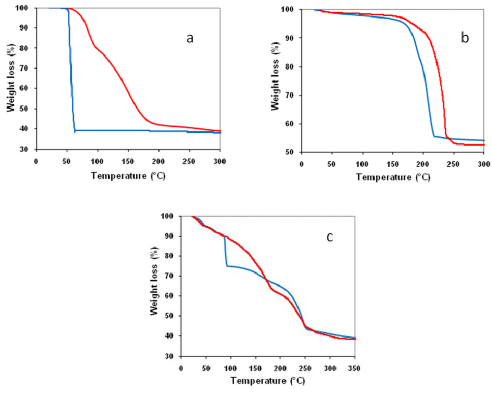
2.2. Effect of Catalyst Thermal Treatment
 ) in air and (
  ) under nitrogen.
) in air and ( ) under nitrogen.
) under nitrogen.
) in air and ( ) under nitrogen. ) in air and ( ) under nitrogen.
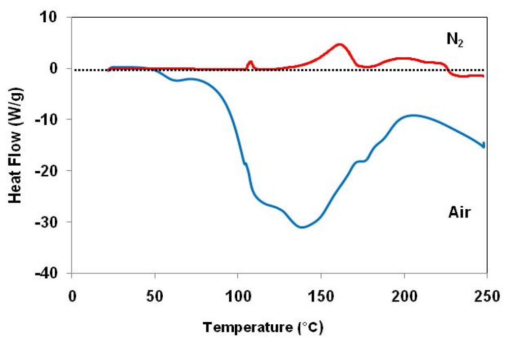

| Catalyst | Drying conditions | Thermal treatment conditions | Surface Area (m2/g) | Au particle size (nm) |
|---|---|---|---|---|
| Fe2.3Au2-Ce-D | Air at 100 °C | - | - | 7.7 |
| Fe2.3Au2-Ce-D-200 | Air at 100 °C | N2 at 200 °C | 64 | 4.6 |
| Fe2.3Au2-Ce-D-400 | Air at 100 °C | N2 at 400 °C | 73 | 4.8 |
 )[NEt4][HFe3(CO)11]; (
  )[NEt4][AuFe4(CO)16] and (
  )[NEt4]4[Au4Fe4(CO)16] cluster salts.
)[NEt4][HFe3(CO)11]; ( )[NEt4][AuFe4(CO)16] and ( )[NEt4]4[Au4Fe4(CO)16] cluster salts.
)[NEt4]4[Au4Fe4(CO)16] cluster salts.
)[NEt4][HFe3(CO)11]; ( )[NEt4][AuFe4(CO)16] and ( )[NEt4]4[Au4Fe4(CO)16] cluster salts.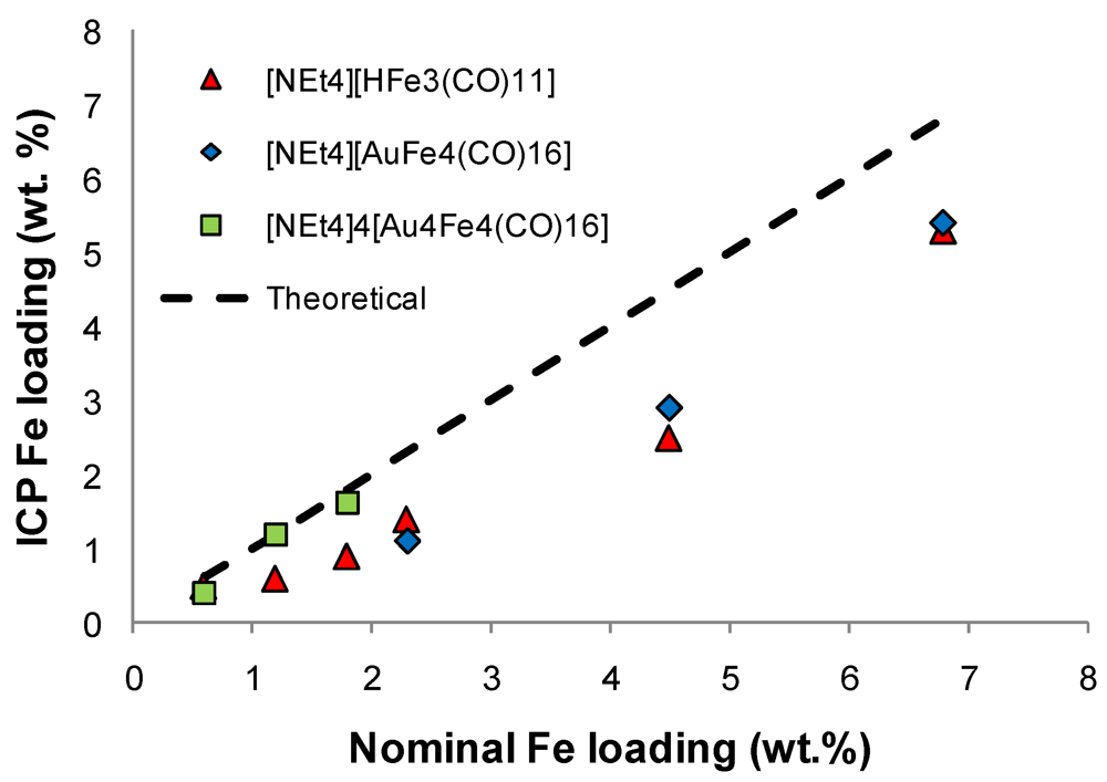
| Catalyst | Drying conditions | Thermal treatment conditions | Nominal Fe loading (wt.%) | Measured Fe loading (wt.%) |
|---|---|---|---|---|
| Fe2.3Au2-Ce-D | Air at 100 °C | - | 2.3 | 1.9 |
| Fe2.3Au2-Ce-D-400 | Air at 100 °C | N2 at 400 °C | 1.6 | |
| Fe2.3Au2-Ce-W | Flowing Wet Air | - | 2.3 | |
| Fe2.3Au2-Ce-W-400 | Flowing Wet Air | N2 at 400 °C | 2.0 |
| Catalyst | Surface Area (m2/g) | Au particle size (nm) |
|---|---|---|
| Fe2.3Au2-Ce-D | - | 7.7 |
| Fe2.3Au2-Ce-D-400 | 73 | 4.8 |
| Fe2.3Au2-Ce-W | - | 8.5 |
| Fe2.3Au2-Ce-W-400 | 70 | 7.1 |
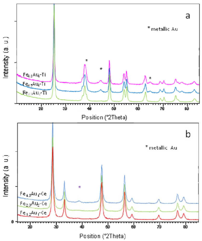
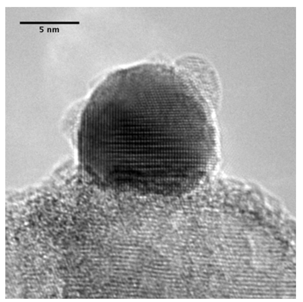
2.3. Characterization of Supported Gold/Iron Catalysts

| Catalyst | Au particle size Fresh (nm) | Au particle size Spent (nm) |
|---|---|---|
| Fe0.6Au2-Ti | 6.0 | 6.0 |
| Fe1.2Au4-Ti | 6.6 | 6.7 |
| Fe1.8Au6-Ti | 7.4 | 7.6 |
| Fe2.3Au2-Ti | <3.0 | 3.7 |
| Fe4.5Au4-Ti | 6.9 | 8.7 |
| Fe6.8Au6-Ti | 7.0 | 7.3 |
| Fe1.2Au1-Ce | <3.0 | 3.0 |
| Fe2.3Au2-Ce | 4.8 | 5.0 |
| Fe4.5Au4-Ce | 9.0 | 9.1 |
| Catalysts | Atomic concentration ratios | Binding Energy (eV) | ||
|---|---|---|---|---|
| Au/Fe XPS | Au/Fe ICP | Au 4f | Fe 2p | |
| Fe2.3Au2-Ti | 0.12 | 0.52 | 83.9 | 710.5 |
| Fe2.3Au2-Ti-s | 0.16 | 0.52 | 83.6 | 710.2 |
| Fe4.5Au4-Ti | 0.07 | 0.47 | 84.0 | 710.6 |
| Fe4.5Au4-Ti-s | 0.07 | 0.47 | 83.9 | 710.3 |
| Fe4.5-Ti | / | / | / | 710.6 |
| Fe1.2Au1-Ce | 0.03 | 0.40 | 83.9 | 710.6 |
| Fe2.3Au2-Ce | 0.04 | 0.30 | 83.8 | 710.4 |
| Fe4.5Au4-Ce | 0.03 | 0.24 | 83.8 | 710.4 |
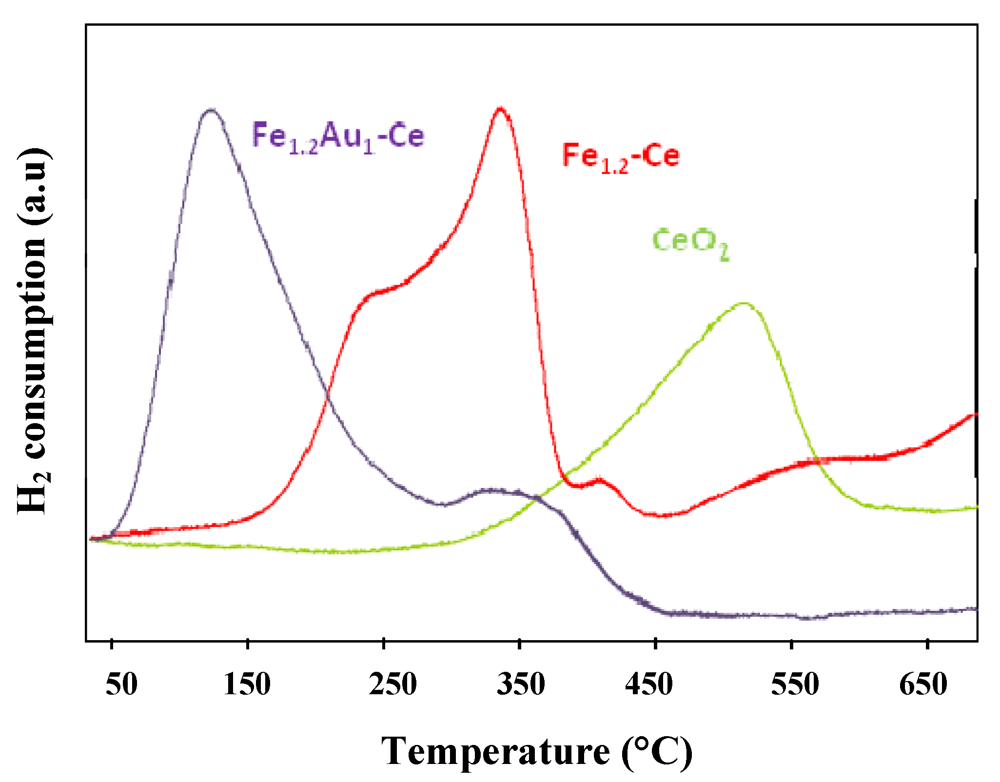
 ) CeO2, (
  ) Fe1.2-Ce and (
  ) Fe1.2Au1-Ce samples.
2.4. Catalysis by Supported Bimetallic Clusters
2.4.1. Toluene and Methanol Combustion
) in function of gold loading for Au/FeOx/CeO2 samples.
) in function of gold loading for Au/FeOx/CeO2 samples. 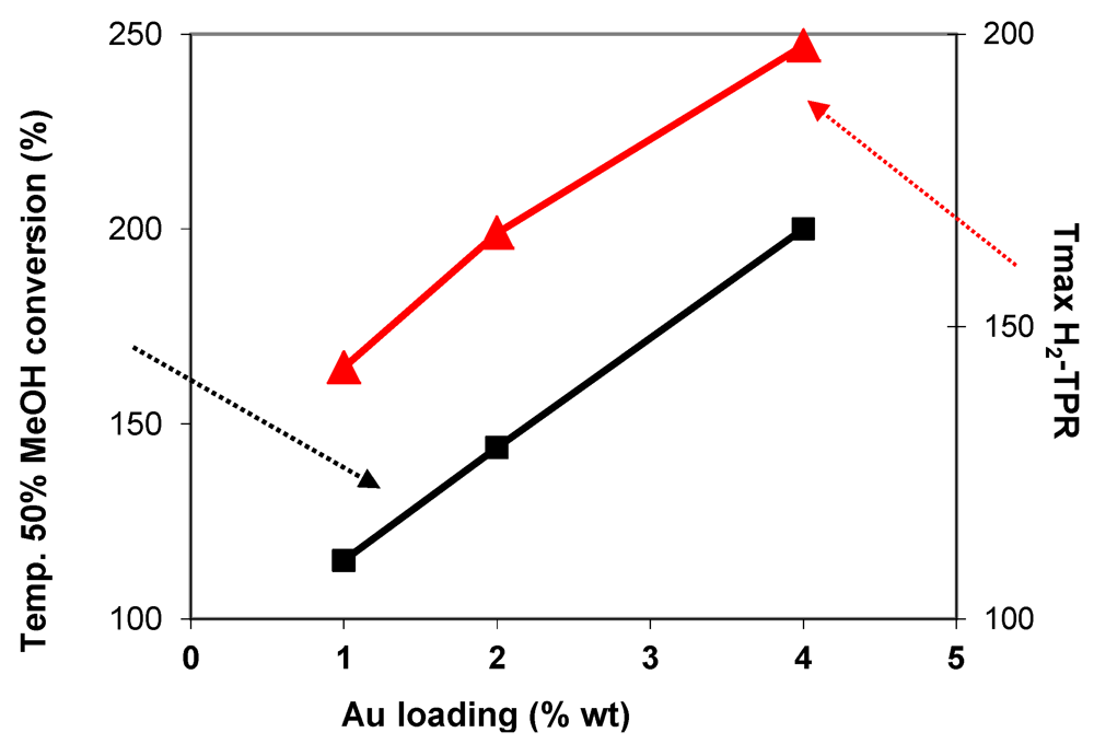
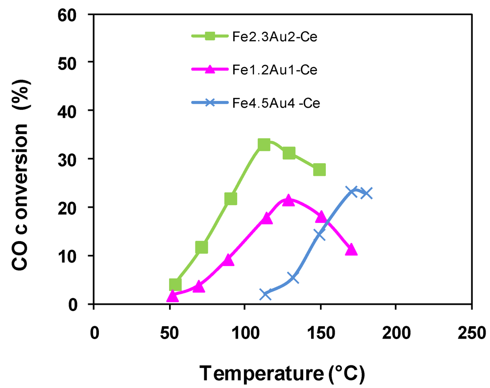
2.4.2. Catalytic Oxidation of CO in the Presence of H2 (PROX)
); Fe2.3Au2-Ce ( ); Fe4.5Au4-Ce (  ).
); Fe2.3Au2-Ce ( ); Fe4.5Au4-Ce ( ).
).
); Fe2.3Au2-Ce ( ); Fe4.5Au4-Ce ( ).
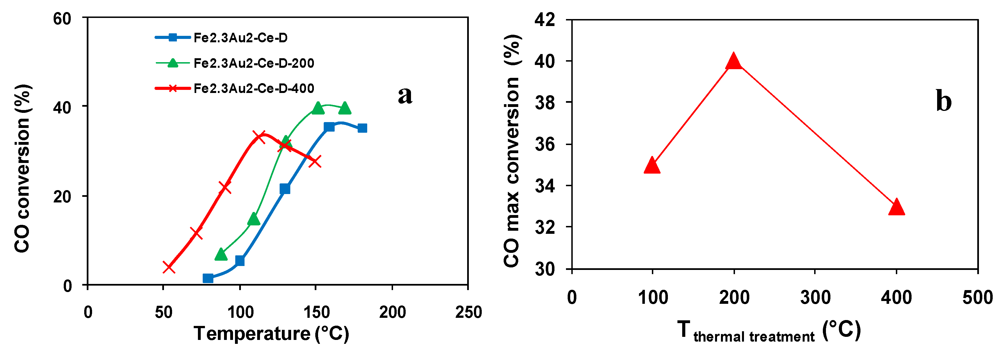
 ); Fe2.3Au2-Ce-D-200 (
  ), Fe2.3Au2-Ce-D-400 (
  ).
); Fe2.3Au2-Ce-D-200 ( ), Fe2.3Au2-Ce-D-400 ( ).
).
); Fe2.3Au2-Ce-D-200 ( ), Fe2.3Au2-Ce-D-400 ( ).


3. Experimental Section
3.1. Catalyst Preparation
3.2. Characterization of the Catalysts
3.3. Catalytic Activity of Supported Clusters for Toluene and Methanol
3.4. Catalytic Activity of Supported Clusters for PROX Reaction
4. Conclusions
Acknowledgments
References
- Haruta, M. Catalysis of gold nanoparticles deposited on metal oxides. CATTECH 2002, 6, 102–115. [Google Scholar] [CrossRef]
- Hashmi, A.S.K.; Hutchings, G.J. Gold catalysis. Angew. Chem. Int. Ed. 2006, 45, 7896–7936. [Google Scholar]
- Centeno, M.A; Paulis, M.; Montes, M.; Odriozola, J.A. Catalytic combustion of volatile organic compounds on gold/titanium oxynitride catalysts. Appl. Catal. B 2005, 61, 177–183. [Google Scholar] [CrossRef]
- Lakshmanan, P.; Delannoy, L.; Richard, V.; Méthivier, C.; Potvin, C.; Louis, C. Total oxidation of propene over Au/xCeO2-Al2O3 catalysts: Influence of the CeO2 loading and the activation treatment. Appl. Catal. B 2010, 94, 117–124. [Google Scholar] [CrossRef]
- Minicò, S.; Scirè, S.; Crisafulli, C.; Galvagno, S. Influence of catalyst pretreatments on volatile organic compounds oxidation over gold/iron oxide. Appl. Catal. B 2001, 34, 277–285. [Google Scholar] [CrossRef]
- Minicò, S.; Scirè, S.; Crisafulli, C.; Maggiore, R.; Galvagno, S. Catalytic combustion of volatile organic compounds on gold/iron oxide catalysts. Appl. Catal. B 2000, 28, 245–251. [Google Scholar] [CrossRef]
- Laguna, O.H.; Romero-Sarria, F.; Centeno, M.A.; Odriozola, J.A. Gold supported on metal-doped ceria catalysts (M = Zr, Zn and Fe) for the preferential oxidation of CO (PROX). J. Catal. 2010, 276, 360–370. [Google Scholar]
- Guczi, L. Bimetallic nano-particles: Featuring structure and reactivity. Catal. Today 2005, 101, 53–64. [Google Scholar] [CrossRef]
- Bordes, E. Synergistic effects in selective oxidation catalysis: Does phase cooperation result in site isolation? Top. Catal. 2001, 15, 131–137. [Google Scholar]
- Alexeev, O.S.; Gates, B.C. Supported bimetallic cluster catalysts. Ind. Eng. Chem. Res. 2003, 42, 1571–1587. [Google Scholar] [CrossRef]
- Edwards, J.K.; Solsona, B.E.; Landon, P.; Carley, A.F.; Herzing, A.; Kiely, C.J.; Hutchings, G.J. Direct synthesis of hydrogen peroxide from H2 and O2 using TiO2-supported Au-Pd catalysts. J. Catal. 2005, 236, 69–79. [Google Scholar]
- Bianchi, C.L.; Canton, P.; Dimitratos, N.; Porta, F.; Prati, L. Selective oxidation of glycerol with oxygen using mono and bimetallic catalysts based on Au, Pd and Pt metals. Catal. Today 2005, 102–103, 203–212. [Google Scholar]
- Venezia, A.M.; La Parola, V.; Deganello, G.; Pawelec, B.; Fierro, J.L.G. Synergetic effect of gold in Au/Pd catalysts during hydrodesulfurization reactions of model compounds. J. Catal. 2003, 215, 317–325. [Google Scholar]
- Pasini, T.; Piccinini, M.; Blosi, M.; Bonelli, R.; Albonetti, S.; Dimitratos, N.; Lopez-Sanchez, J.A.; Sankar, M.; He, Q.; Kiely, C.J.; et al. Selective oxidation of 5-hydroxymethyl-2-furfural using supported gold-copper nanoparticles. Green Chem. 2011, 13, 2091–2099. [Google Scholar]
- Carrettin, S.; Hao, Y.; Aguilar-Guerrero, V.; Gates, B.C.; Trasobares, S.; Calvino, J.; Corma, A. Increasing the number of oxygen vacancies on TiO2 by doping with iron increases the activity of supported gold for CO oxidation. Chem. Eur. J. 2007, 13, 7771–7779. [Google Scholar]
- Moreau, F.; Bond, G.C. Preservation of the activity of supported gold catalysts for CO oxidation. Top. Catal. 2007, 44, 95–101. [Google Scholar]
- Gluhoi, A.C.; Bogdanchikova, N.; Nieuwenhuys, B.E. The effect of different types of additives on the catalytic activity of Au/Al2O3 in propene total oxidation: Transition metal oxides and ceria. J. Catal. 2005, 229, 154–162. [Google Scholar]
- Penkova, A.; Chakarova, K.; Laguna, O.H.; Hadjiivanov, K.; Romero-Sarria, F.; Centeno, M.A.; Odriozola, J.A. Redox chemistry of gold in a Au/FeOx/CeO2 CO oxidation catalyst. Catal. Commun. 2009, 10, 1196–1202. [Google Scholar] [CrossRef]
- Laguna, O.H.; Centeno, M.A.; Arzamendi, G.; Gandia, L.M.; Romero-Sarria, F.; Odriozola, J.A. Iron-modified ceria and Au/ceria catalysts for total and preferential oxidation of CO (TOX and PROX). Catal. Today 2010, 157, 155–159. [Google Scholar]
- Siani, A.; Captain, B.; Adams, R.D.; Alexeev, O.S.; Amiridis, M.D. Synthesis and Structural Characterization of SiO2-Supported PtFe Catalysts Prepared from PtFe2(C8H12)(CO)8. Top. Catal. 2011, 54, 318–333. [Google Scholar]
- Schay, Z.; Lázár, K.; Mink, J.; Guczi, L. Spectroscopic and catalytic studies on metal carbonyl clusters supported on Cab-O-Sil. II. Impregnation and decomposition of Ru3(CO)12 and the mixture of Ru3(CO)12 and Fe3(CO)12. J. Catal. 1984, 87, 179–195. [Google Scholar]
- Guczi, L.; Beck, A. Elementary steps in the formation of bimetallic catalysts derived from carbonyl clusters. Polyhedron 1988, 22–23, 2387–2392. [Google Scholar] [CrossRef]
- Guczi, L.; Beck, A.; Dobos, S. Metal clusters: A model for a molecular surface switch in the genesis of highly dispersed metal particles. J. Mol. Catal. 1992, 74, 317–322. [Google Scholar] [CrossRef]
- Femoni, C.; Kaswalder, F.; Iapalucci, M.C.; Longoni, G.; Zacchini, S. The possible role of metal carbonyl clusters in nanoscience and nanotechnologies. Coord. Chem. Rev. 2006, 250, 1580–1604. [Google Scholar]
- Femoni, C.; Iapalucci, M.C.; Longoni, G.; Tiozzo, C.; Zacchini, S. An organometallic approach to gold nanoparticles: Synthesis and X-ray structure of CO-protected Au21Fe10, Au22Fe12, Au28Fe14, and Au34Fe14 clusters. Angew. Chem. Int. Ed. 2008, 47, 6666–6669. [Google Scholar]
- Lopez-Acevedo, O.; Rintala, J.; Virtanen, S.; Femoni, C.; Tiozzo, C.; Grönbeck, H.; Pettersson, M.; Häkkinen, H. Characterization of iron-carbonyl-protected gold clusters. J. Am. Chem. Soc. 2009, 131, 12573–12575. [Google Scholar]
- Femoni, C.; Iapalucci, M.C.; Longoni, G.; Tiozzo, C.; Wolowska, J.; Zacchini, S.; Zazzaroni, E. New hybrid semiconductor materials based on viologen salts of bimetallic Fe-Pt and Fe-Au carbonyl clusters: First structural characterization of the diradicalπ-dimer of the diethyl viologenmonocation and EPR evidence of its triplet state. Chem. Eur. J. 2007, 13, 6544–6554. [Google Scholar] [CrossRef]
- Albonetti, S.; Bonelli, R.; Epoupa Mengou, J.; Femoni, C.; Tiozzo, C.; Zacchini, S. Gold/Iron carbonyl clusters as precursors for TiO2 supported catalysts. Catal. Today 2008, 137, 483–488. [Google Scholar]
- Albonetti, S.; Bonelli, R.; Delaigle, R.; Femoni, C.; Gaigneaux, E.M.; Morandi, V.; Orlandi, L.; Tiozzo, C.; Zacchini, S.; Trifirò, F. Catalytic combustion of toluene over cluster-derived gold/iron catalysts. Appl. Catal. A 2010, 372, 138–146. [Google Scholar] [CrossRef]
- Albonetti, S.; Bonelli, R.; Morandi, V.; Ortolani, L.; Riccobene, P.M.; Scirè, S.; Zacchini, S. Design of nano-sized FeOx and Au/FeOx catalysts supported on CeO2 for total oxidation of VOC. Appl. Catal. A 2011, 395, 10–18. [Google Scholar] [CrossRef]
- Guczi, L.; Frey, K.; Beck, A.; Peto, G.; Daroczi, C.S.; Kruse, N.; Chnakin, S. Iron oxide overlayers on Au/SiO2/Si(1 0 0): Promoting effect of Au on the catalytic activity of iron oxide in CO oxidation. Appl. Catal. A 2005, 291, 116–125. [Google Scholar] [CrossRef]
- Munteanu, G.; Ilieva, L.; Andreeva, D. Kinetic parameters obtained from TPR data for α-Fe2O3 and Au/α-Fe2O3 systems. Thermochim. Acta 1997, 291, 171–177. [Google Scholar] [CrossRef]
- Jozwiak, W.K.; Kaczmarek, E.; Maniecki, T.P.; Ignaczak, W.; Maniukiewicz, W. Reduction behavior of iron oxides in hydrogen and carbon monoxide atmospheres. Appl. Catal. A 2007, 326, 17–27. [Google Scholar] [CrossRef]
- Li, K.Z.; Wang, H.; Wey, Y.G. Selective oxidation of carbon using iron-modified cerium oxide. J. Phys. Chem. C 2009, 113, 15288–15297. [Google Scholar]
- Kaneko, H.; Miura, T.; Ishihara, H.; Taku, S.; Yokoyama, T.; Nakajima, H.; Tamaura, Y. Reactive ceramics of CeO2-MOx (M = Mn, Fe, Ni, Cu) for H2 generation by two-step water splitting using concentrated solar thermal energy. Energy 2007, 32, 656–663. [Google Scholar] [CrossRef]
- Scirè, S.; Minicò, S.; Crisafulli, C.; Satriano, C.; Pistone, A. Catalytic combustion of volatile organic compounds on gold/cerium oxide catalyst. Appl. Catal. B 2003, 40, 43–49. [Google Scholar] [CrossRef]
- Scirè, S.; Crisafulli, C.; Minicò, S.; Condorelli, G.; di Mauro, G.A. Selective oxidation of CO in H2-rich stream over gold/iron oxide: An insight on the effect of catalyst pretreatment. J. Mol. Catal. A 2008, 284, 24–32. [Google Scholar] [CrossRef]
- Guczi, L.; Beck, A.; Frey, K. Role of promoting oxide morphology dictating the activity of Au/SiO2 catalyst in CO oxidation. Gold Bull. 2009, 42, 5–12. [Google Scholar] [CrossRef]
- Albano, V.G.; Calderoni, F.; Iapalucci, M.C.; Longoni, G.; Monari, M. Synthesis of [AuFe2(CO)8]3− and [Au4Fe4(CO)16]4−: X-ray structure of the [Au4Fe4(CO)16]4− cluster anion in its [NEt4]+ salt. J. Chem. Soc. Chem. Commun. 1995, 4, 433–434. [Google Scholar]
- Albano, V.G.; Aureli, R.; Iapalucci, M.C.; Laschi, F.; Longoni, G.; Monari, M.; Zanello, P. Synthesis, characterization and electrochemical behaviour of the [Fe4Au(CO)16]n− (n = 1,2,3) clusters. X ray structure of [NMe3CH2Ph][Fe4Au(CO)16]Cl. J. Chem. Soc. Chem. Commun. 1993, 19, 1501–1502. [Google Scholar]
- Bonelli, R.; Lucarelli, C.; Pasini, T.; Liotta, L.F.; Zacchini, S.; Albonetti, S. Total oxidation of volatile organic compounds on Au/FeOx catalysts supported on mesoporous SBA-15 silica. Appl. Catal. A 2011, 400, 54–60. [Google Scholar] [CrossRef]
- Farmery, K.; Kilner, M.; Greatrex, R.; Greenwood, N.N. Structural studies of the carbonylate and carbonyl hydride anions of iron. J. Chem. Soc. A 1969, 2339–2345. [Google Scholar]
- Albonetti, S.; Bonelli, R.; Delaigle, R.; Gaigneaux, E.M.; Femoni, C.; Riccobene, P.M.; Scirè, S.; Tiozzo, C.; Zacchini, S.; Trifirò, F. Design of nano-sized FeOx and Au/FeOx supported catalysts for total oxidation of VOC and preferential oxidation of CO. Stud. Surf. Sci. Catal. 2010, 175, 786–788. [Google Scholar]
© 2012 by the authors; licensee MDPI, Basel, Switzerland. This article is an open-access article distributed under the terms and conditions of the Creative Commons Attribution license (http://creativecommons.org/licenses/by/3.0/).
Share and Cite
Bonelli, R.; Zacchini, S.; Albonetti, S. Gold/Iron Carbonyl Clusters for Tailored Au/FeOx Supported Catalysts. Catalysts 2012, 2, 1-23. https://doi.org/10.3390/catal2010001
Bonelli R, Zacchini S, Albonetti S. Gold/Iron Carbonyl Clusters for Tailored Au/FeOx Supported Catalysts. Catalysts. 2012; 2(1):1-23. https://doi.org/10.3390/catal2010001
Chicago/Turabian StyleBonelli, Rosa, Stefano Zacchini, and Stefania Albonetti. 2012. "Gold/Iron Carbonyl Clusters for Tailored Au/FeOx Supported Catalysts" Catalysts 2, no. 1: 1-23. https://doi.org/10.3390/catal2010001
APA StyleBonelli, R., Zacchini, S., & Albonetti, S. (2012). Gold/Iron Carbonyl Clusters for Tailored Au/FeOx Supported Catalysts. Catalysts, 2(1), 1-23. https://doi.org/10.3390/catal2010001