Article

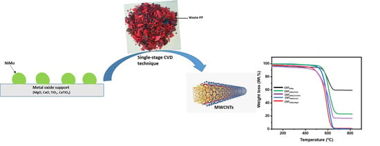
Effect of Different Catalyst Supports on the Quality, Yield and Morphology of Carbon Nanotubes Produced from Waste Polypropylene Plastics

by
Helen Uchenna Modekwe
1,
Messai Adenew Mamo
2,
Kapil Moothi
1 and
Michael Olawale Daramola
3,*
1
Department of Chemical Engineering, Faculty of Engineering and the Built Environment, Doornfontein Campus, University of Johannesburg, P. O. Box 17011, Johannesburg 2028, South Africa
2
Research Centre for Synthesis and Catalysis, Department of Chemical Science, Doornfontein Campus, Faculty of Science, University of Johannesburg, P. O. Box 17011, Johannesburg 2028, South Africa
3
Department of Chemical Engineering, Faculty of Engineering, Built Environment and Information Technology, University of Pretoria, Private Bag X20, Hatfield, Pretoria 0028, South Africa
*
Author to whom correspondence should be addressed.
Catalysts 2021, 11(6), 692; https://doi.org/10.3390/catal11060692
Submission received: 13 April 2021 / Revised: 2 May 2021 / Accepted: 4 May 2021 / Published: 30 May 2021

Abstract

:
The role of the effect of the support on the reactivity of heterogeneous catalysts cannot be over-emphasized. Therefore, the study documented in this article investigated the effect of different metal oxide supports (MgO, CaO and TiO2) and mixed oxide supports (CaTiO3) on the performance of a bimetallic NiMo catalyst prepared via the sol–gel method during the catalytic growth of carbon nanotubes (CNTs) from waste polypropylene (PP). Waste PP was pyrolyzed at 700 °C in a single-stage chemical vapor deposition reactor and off-gas was utilized in-situ as a cheap carbon feedstock for the growth of CNTs under similar conditions for all the prepared NiMo catalysts (supported and unsupported). The structures of the prepared catalysts and deposited carbon were extensively characterized using X-ray diffraction (XRD), temperature-programmed reduction (TPR), transmission electron microscopy (TEM), thermogravimetric analysis (TGA), etc. The catalytic performance of NiMo supported and unsupported catalysts was evaluated in terms of the yield, purity, and morphology of synthesized CNTs. The results revealed that the stabilizing role of supports is fundamental in preventing nanoparticle agglomeration and aggregation, thereby resulting in improved yield and quality of CNTs. Supported NiMo catalysts produced better aligned graphitic and high-quality CNTs. The NiMo/CaTiO3 catalyst produced the highest carbon of 40.0%, while unsupported NiMo produced low-quality CNTs with the lowest carbon yield of 18.4%. Therefore, the type of catalyst support and overall stability of catalytic materials play significant roles in the yield and quality of CNTs produced from waste PP.

Graphical Abstract

1. Introduction

Polypropylene represents the second largest polymer market worldwide, accounting for more than 25% of the global polymer demand, on an estimated annual average growth rate of around 5.2% [1,2,3]. Recycling technologies for waste PP materials and products are usually low-grade since waste PP is limited to a small number of reprocessing and reuse cycles as these products lose some of their essential properties, such as strength and stability, after a number of recycling cycles; nevertheless, the carbon content remains intact [4]. From economic and environmental points of view, low-value waste PP has been widely studied as an inexpensive feedstock for high-value-added carbon nanotubes [5,6,7]. Recently, Cai et al. investigated and compared CNT production over an Fe/Al2O3 catalyst during the catalytic pyrolysis of different types of plastic wastes comprising polypropylene, polyethylene (PE), i.e., low-density polyethylene (LDPE) and high-density polyethylene (HDPE), and polystyrene (PE), i.e., (high-impact and general-purpose). The authors reported that PP and PE are more suitable for CNT synthesis, based on the formation of better-quality, higher-yield, and smooth CNTs when compared to CNTs obtained using PS feedstocks [8]. Since carbon nanotubes were first discovered by Ijima, a great deal of research has been undertaken in this field on several potential applications of CNTs which are very plausible given their tremendous chemical, electrical, optical, thermal, and mechanical properties [9]. Currently, plastic-derived CNTs are rarely used in commercial applications because they lack identical structures and property uniformity.
Since there is a recognizable dependence of the CNTs’ diameter on the catalyst particle size, significant efforts have been made by researchers over the past two decades and more to synthesize CNTs with a nearly uniform diameter by controlling the dispersion of active metals in the catalyst, which is believed to be responsible for CNT growth [10,11]. Ni-based catalysts are well studied as favorable catalysts in the conversion of hydrocarbons into CNTs due to their effective catalytic activity, non-toxicity, and relatively low cost [12]. The synergistic action of two metals enhances their overall catalytic activity and selectivity [13]. Bimetallic catalysts of Ni, such as Ni-Fe, Ni-Mg, Ni-Cu, Ni-Al, Ni-Mo, and Ni-Co, have been widely studied. Amongst them, Mo metal has been demonstrated to assist in reducing the synthesis temperature associated with the production of CNTs by enhancing the mobility of active metal particles over the support and also help in controlling wall graphitization, number, and yield of CNTs [14,15].
Catalyst supports play a dominant role in stabilizing and enhancing the catalytic properties of the active metal catalyst in catalytic hydrocarbon conversion processes. Thermal and chemical stability of the support material are essential criteria in selecting support materials for CNT synthesis in a CVD process; additionally, surface area and porosity are also important. Suitable metal oxide supports or mixed oxides such as Al2O3, SiO2, MgO, CaO, TiO2, TiO2-Al2O3, and CaTiO3 could effectively fine tune the electronic properties of the active metal phases [16]. Li et al. investigated the synergistic effect between Mg and Mo in Ni-Mo-MgO catalysts during the one-step carbonization of polystyrene into CNTs. The authors reported that the addition of Mo resulted in the formation of small-sized catalyst particles, which resulted in the formation of carbon spheres, whereas the addition of Mg showed no effect on the catalyst particle size but efficiently improved the carbon solubility and yield. However, combining Mo and Mg resulted in the growth of CNTs of optimal yield and morphology [17].
In a metal-supported catalyst, the metal particles are at the support surface, but are partially embedded within the catalyst matrix. The more metal particles are strongly attached to the support surface, the higher the chances if minimizing sintering, sustaining good dispersion and mobility of catalyst active metal phases, and stabilizing the size distribution of the active particle and also resisting catalyst deactivation [11,18,19]. Therefore, the active metal–support interaction is one of the factors that controls the stability of a catalytic material in preventing metal particle sintering [20], as well as the morphology, size, and yield of CNTs during their growth. Nahil and co-workers studied the influence of different metals (Mg, Ce, Zn, Mn or Ca) added to Ni-based catalysts (Ni-Metal-Al) in the production of CNTs from waste PP. Amongst the catalysts investigated, the Ni-Mn-Al catalyst gave the highest deposition of filamentous carbon. The nature of the interaction between Ni particles and the support was reported to be the most critical for their improved activity [7]. During CNTs’ growth, the kind of interaction existing between the catalyst metal and support results in two distinctive growth models. The interaction could be strong or weak, leading to nanotubes of “base growth model” or “tip growth model”, respectively [21].
Though several results have been reported in the literature on the performance of different catalyst supports during the catalytic conversion of PP into CNTs using a CVD setup, there are disparities in the reported results. In addition, there is no adequate comparison of the effect of different catalyst supports and the catalysts thereof on the reactivity of these catalysts during the catalytic conversion of waste PP to CNTs. This omission could be attributed to the fact that different studies have employed different synthesis/reaction conditions. For instance, different authors have used different reaction times, concentrations or loadings, temperatures, gas (inert) environments, etc., during the conversion, thereby resulting in CNTs of different quality and yield. Additionally, different studies have employed different methods in the quantification of CNT yield and polymer converted to CNTs, etc. [22].
Motivated by the above statements, the effect of four different catalyst supports (metal oxides and mixed oxide materials: MgO, TiO2, CaO, and CaTiO3) on the performance of a bimetallic NiMo catalyst during the synthesis of CNTs from waste PP was studied. The quality, yield, and morphology of PP waste-derived CNTs were explored to establish a relationship between the Ni-Mo catalyst, the different catalyst supports, and their corresponding catalytic activity. The catalytic performance of the NiMo catalyst, supported on different metal oxide and mixed oxide supports for CNT growth from waste PP, has not been explicitly investigated. This work aimed to systematically compare and present clear information on the effect of different catalyst supports, specifically on how it affects the yield, morphology, and crystallinity (quality) of CNTs produced from waste PP under similar growth conditions, using a single-stage CVD reactor. Therefore, the objective of the present work was to compare the activities of the NiMo parent catalyst supported on different supports for the synthesis of CNTs from waste PP plastics. The novelty of this study lies in its presentation of first-hand information on the performance of different supported NiMo catalysts towards the growth of waste PP-derived CNTs. The NiMo catalyst was chosen because optimum loading and composition have been carefully studied by other researchers [23,24]. All four supported NiMo catalysts under study were prepared using similar Ni, Mo, and support metal loadings.

2. Results and Discussion

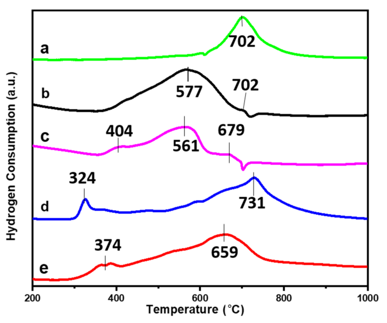
2.1. Characterization of Catalysts

The XRD patterns of the Ni-Mo catalyst supported on CaO, TiO2, MgO, and CaTiO3 and unsupported NiMo are comparatively shown in Figure 1. The respective phases of interest present in all the calcined catalysts are identified and labeled. There is a remarkable degree of similarity in the crystal position of some of the diffraction peaks of the catalysts under study. Characteristic diffraction peaks associated with cubic phase crystalline structures of NiO (PDF 00-432-9325) were detected at 2θ = 37.5°, 43.0°, 62.8°, 75.4°, and 79.2°, which corresponded to the (111), (200), (2,2,0), (3,1,1), and (2,2,2) diffraction planes, respectively, for all the catalysts. For the NiMo/TiO2 catalyst, well-resolved diffraction peaks at 2θ = 24.3°, 33.7°, 37.6°, and 49.4° were observed, which corresponded to the hexagonal crystalline structure of ilmenite (nickel titanate), NiTiO3 (PDF 01-075-3757). Peaks associated with NiMoO4 species (PDF 01-086-0361) were observed for all catalysts under study. For the NiMo/CaTiO3 catalyst, diffraction peaks of cubic perovskite-like Ca(TiO3) structure phases overlapped with NiMoO4 and NiO peaks, as observed in Figure 1E. Again, similar peaks were observed to coincide in the NiMo/MgO catalyst in Figure 1B. These overlaps could be attributed to the degree of dispersion of NiO and MoO3 species on the surfaces of CaTiO3 and MgO supports. The crystallite size of the NiO phase present in all prepared catalysts is shown in Table 1. NiMo/CaTiO3 and NiMo/MgO catalysts displayed the highest metal crystallite-sized particles among all catalysts under study, probably due to the agglomeration of metal particles. It is also worth mentioning that a similar average crystallite size of the NiO phase (9.2–11.4 nm) was also reported for the NiMo-supported CaTiO3 catalyst with analogously overlapped phases [25].
Nitrogen adsorption–desorption isotherms of NiMo supported and unsupported catalysts exhibited type IV isotherms with H3 hysteresis loops associated with mesoporous materials (2 nm ˂ pore size ˂ 50 nm); see Supplementary Materials Figure S1. The type-H3 hysteresis loop at high relative pressure P/Po, resulting from complete filling and emptying of mesopores by capillary condensation, indicated that all catalysts had slit-shaped mesoporous structures [26,27]. Apart from the NiMo/TiO2 and NiMo/CaTiO3 isotherms, other catalysts’ isotherms show steep capillary condensation steps, indicating non-uniformity of their mesopores [28]. It could be seen that there was a sudden intersection of the desorption branch with the adsorption branch at a relative pressure of around 0.63 for the NiMo/MgO catalyst, which may be a result of pore blockage due to the different metal cations present in the bulk surfaces, resulting in pores being inaccessible [29,30]. The NiMo/CaTiO3 catalyst showed hysteresis loop closure at P/Po = 0.88, indicating the presence of large mesopores. The surface area, pore size, and pore volume of all calcined catalysts under study are shown in Table 1. It could be observed that all catalysts displayed decreased BET specific surface area compared to the unsupported NiMo catalyst (72.5 m2g−1). The observed decrease in the BET surface area of the supported catalyst could be due to the blocking of mesopores arising from the introduction of more metal species from the support materials. A similar low-BET surface area of 23.68 m2g−1 was reported by [31] for a NiO/TiO2 catalyst. Li et al. [28] also synthesized NiMo-supported TiO2 catalysts promoted with potassium via the incipient wet impregnation technique and the authors reported a low BET surface area between 39.7 and 45.7 m2g−1 for their catalysts. In our previous study [25], NiMo-supported CaTiO3 catalysts synthesized by the sol–gel method also showed a low BET surface area between 7.7 and 17.4 m2g−1.
SEM images of all prepared supported and unsupported NiMo catalysts are shown in Figure 2. All catalysts showed either a dense platelet, flake-like, or foamy morphology. EDS analysis elucidated the elemental components of all catalysts under study, as shown in Table 2. Further insights into the morphology of the different NiMo-supported and unsupported catalysts were obtained using TEM analysis and the results are presented in Figure 3. Accordingly, unsupported NiMo particles showed agglomerated structures with an average particle size of 10–24 nm. Particles of NiMo/MgO and NiMo/TiO2 are of spherical morphology with particle sizes of 10–26 nm and 8–22 nm, respectively. NiMo/CaO possessed well-dispersed, sponge-like particles with a particle size distribution of 6–16 nm, while the NiMo/CaTiO3 catalyst showed fairly dispersed metal particles on the surfaces of the supports, with some patches of aggregated particles with sizes of 8–28 nm. The SAED pattern is shown in Figure 3F–J; all catalysts presented concentric circles of polycrystalline, nanostructured material for all NiMo catalysts under study. Diffraction rings are assigned to the characteristic hkl values or typical planes of Ni [32,33]. The obtained SAED data (Figure 3F-J) correlate with the diffraction data obtained from XRD in Figure 1, which also reveal the existence of other phases in NiMo-supported and unsupported catalysts.
The H2-TPR profile of all NiMo catalysts studied is shown in Figure 4. All catalysts presented different reduction profiles, indicating differences in the interaction between the active phase and the different supports; nevertheless, all catalyst profiles exhibited a single, well-defined reduction signal below 750 °C. The reduction profile of the unsupported NiMo catalyst displayed a weak shoulder at 374 °C, indicating the reduction of Ni2+ species to Ni0, and a major high-temperature reduction maximum peak at 659 °C. According to the literature [34,35,36], it is known that the reduction of Ni2+ to its metallic stable state is a one-step reduction (i.e., Ni2+ → Ni0) at around 300–400 °C, while the reduction of MoO3 species is more complex, Mo6+ → Mo4+ → Mo0, and as such requires higher reduction temperatures [37]. Therefore, the first shoulder peak could be attributed to the complete reduction of weakly bound nickel species in the NiMo and NiO phases from Ni2+ to Ni0 and could also be ascribed to the partial reduction of MoO3 (Mo6+ to Mo4+). Li et al. [28] stated that the reduction of Mo6+ to Mo4+ occurs at temperatures below 450 °C. A well-defined high-temperature peak at 659 °C could be attributed to the complete reduction of the MoO3—that is, Mo4+ to Mo0 species. For NiMo-supported CaTiO3 and MgO catalysts, the reduction temperatures for the major reduction peaks shifted to higher temperatures, as shown in Figure 4a,d; these results could be attributed to the increased strong interactions between the support and Ni-Mo oxide catalyst structure, resulting in overlapping phases. The strong interaction could be also due to the high structural stability constituted by both MgO and CaTiO3 matrices; it is known that there is restricted reducibility of the NiMg complex [38], which is in agreement with the XRD result. Another notable and important observation was made in Figure 4b,c, for the NiMo/TiO2 and NiMo/CaO catalysts, respectively. For the NiMo/TiO2 catalyst, the well-resolved reduction peak at 577 °C is ascribed to the reduction of NiTiO3 and a shoulder at 702 °C is also attributed to the complete reduction of metastable NiMoO4 (MoO3) phases, as observed in Figure 1 (XRD profile), since NiMoO4 phases are metastable at temperatures around 700 °C [31,34,39].

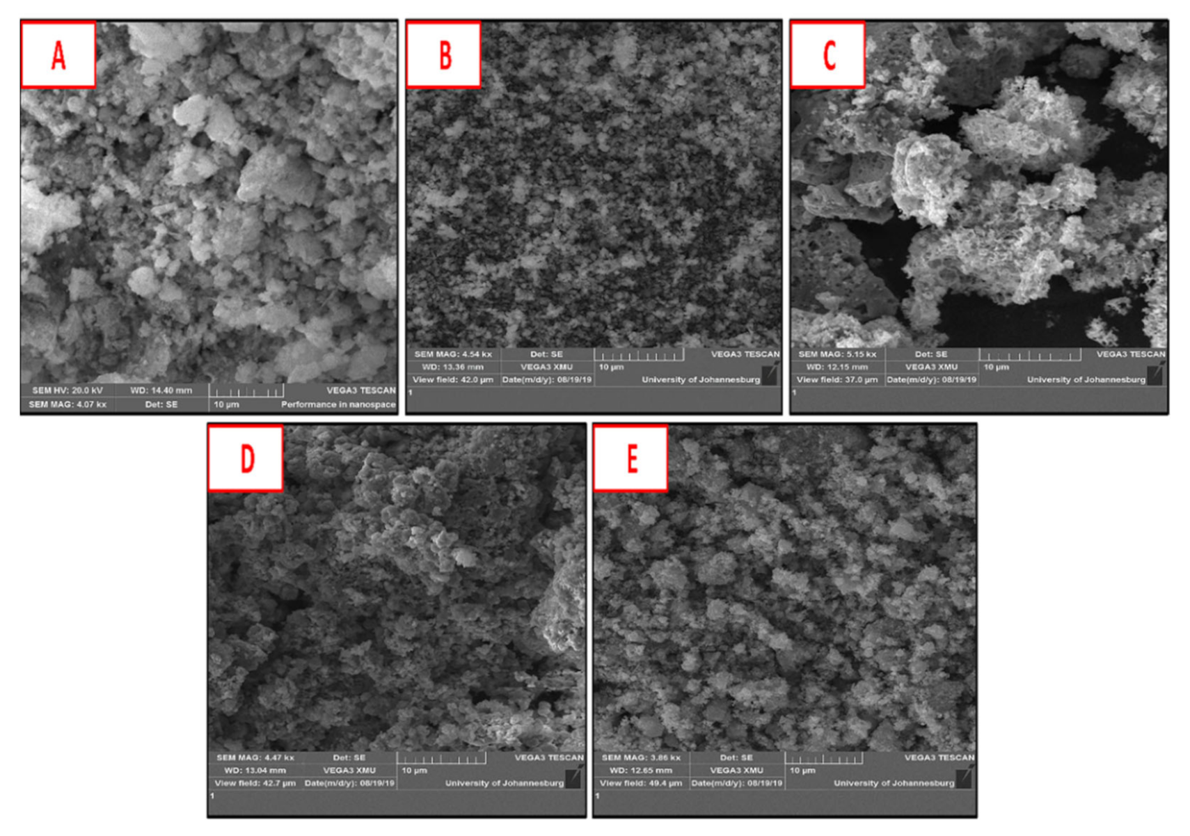
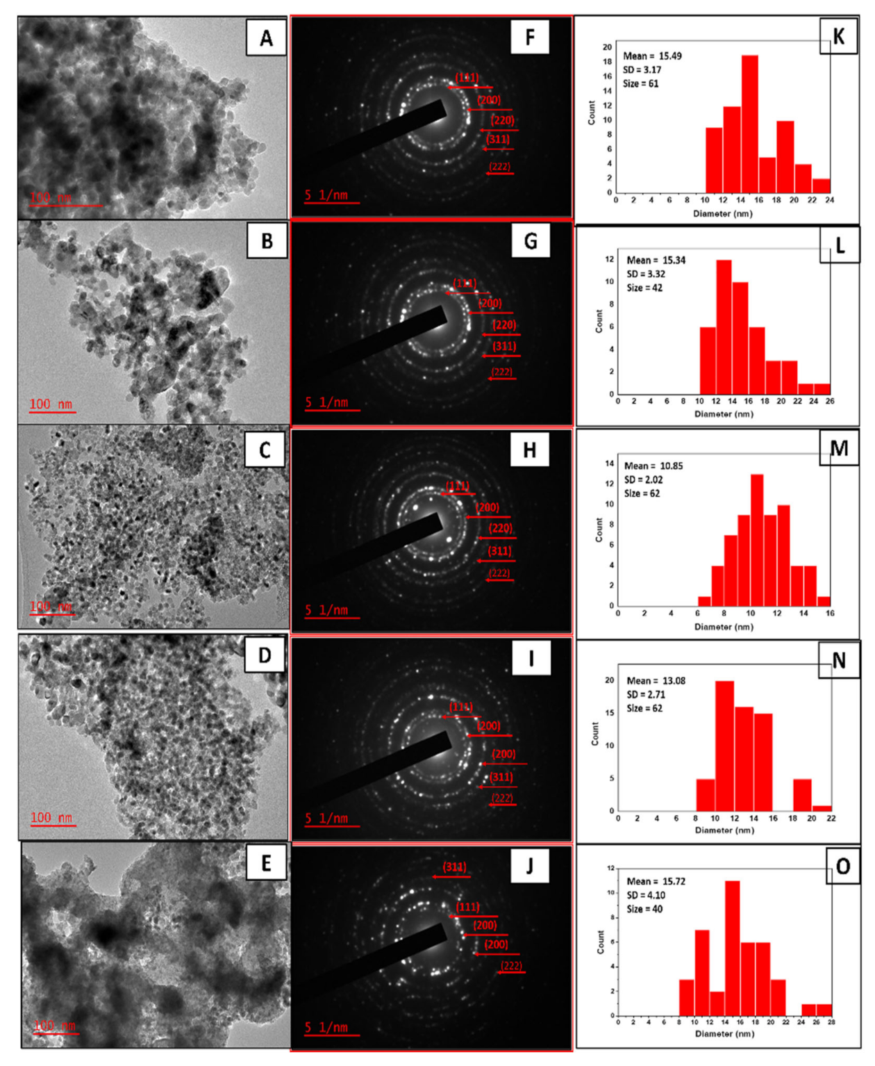
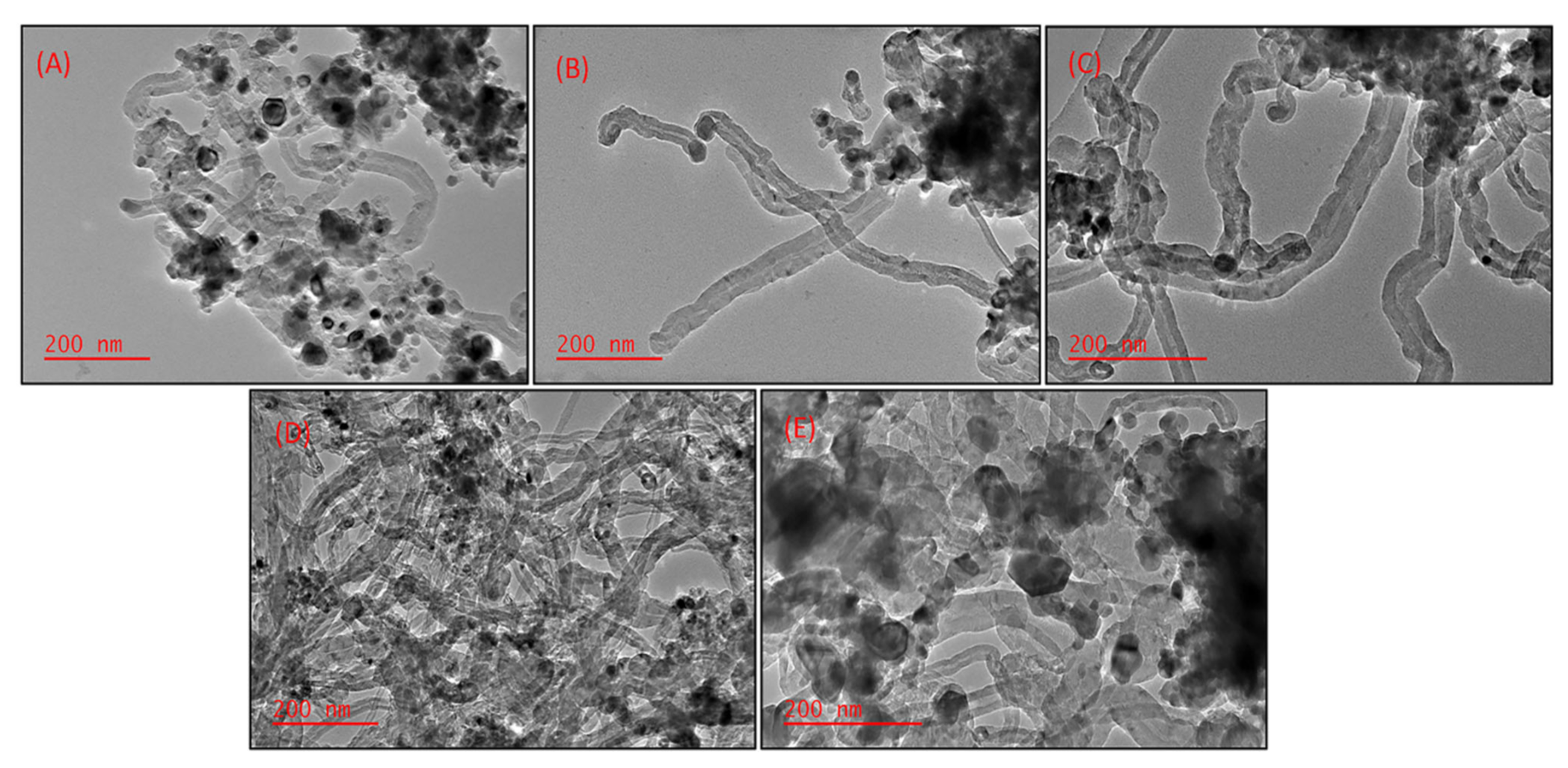
2.2. Effect of Different Supports on the Morphology of CNTs

Figure 5 depicts TEM micrographs and outer diameter distribution histograms of all as-produced carbon nanomaterials. All deposited carbon on the surfaces of NiMo-supported and unsupported catalysts exhibited hollow filamentous nanostructures, suggesting multi-walled CNTs (MWCNTs). It could be observed that all as-grown MWCNTs displayed tip-growth mode, with the metal nanoparticle propagating at the tip of the tubes, except for MWCNTs deposited on the NiMo/CaTiO3 catalyst—that is, (CNTNiMo/CaTiO3)—which showed base growth mode, depicting a moderately strong interaction with the support, which agrees with the TPR result. Figure 5F–J depict the outer diameter distribution histograms of all nanotubes deposited over supported and unsupported NiMo catalysts. All MWCNTs obtained over supported NiMo catalysts exhibited nanotubes with almost near-uniform range diameters, except for CNTNiMo deposited on the surface of the unsupported NiMo catalyst, which displayed a wide average outer diameter of approximately 25.08 nm ± 7.538 nm, as shown in Table 3. Shen and Lua [40] and Ni et al. [41] observed that the size of Ni catalysts usually changes at temperatures above 500 °C, resulting in Ni catalysts being rapidly deactivated because of the thermal fluctuation during CNT production. Similarly, Zhang and co-workers [24] suggested that at high temperatures, originally small particle-sized Ni nanoparticles have a tendency to assemble and form large clusters of particles during CNT nucleation and growth. These large, clustered particles could result in the formation of CNTs with a large diameter range since, according to the literature, CNTs’ diameter depends on the particle size of the active metal on the catalyst support [42,43]. Therefore, the non-existence of the stabilizing effect of the catalyst support in the unsupported NiMo catalyst could be the reason for the agglomeration of active metal particles during in-situ reduction and CNT synthesis, leading to the formation of CNTs with a larger diameter range [24,36]. As shown in Figure 5A,B after CNTNiMo/CaO and CNTNiMo/MgO were purified, the lengths of nanotubes were shortened: this is due to the acid treatment and purification process. Meanwhile, nanotubes deposited on the unsupported NiMo catalyst—that is, CNTNiMo—are bendy, with more encapsulated metal particles being observed. Therefore, the above results suggest that the morphology of MWCNTs strongly depends on the type of catalyst support.
A similar result was reported by Takenaka et al. [43], who studied the catalytic performance (activity, lifetime, and CNT yield) of Co-supported MgO, Al2O3, SiO2, and TiO2 catalysts during methane decomposition at 500 °C. They suggested that the catalytic activity of Co-supported catalysts depended on the type of catalytic support. Wang and co-workers [44] also investigated the effect of different supports on the selectivity control towards single-wall carbon nanotubes’ (SWCNTs) growth from carbonyl (CO), and they proposed that different supports either disrupt or enhance the synergistic effect between Co and Mo species, resulting in the formation of different Co phases, which were responsible for differences in their observed selectivity towards SWCNTs’ growth. Furthermore, they indicated that the SiO2 and MgO support improved the selectivity towards SWCNTs with a narrow diameter range, while Co-Mo supported on Al2O3 and TiO2 perturbs the interaction between Co and Mo species, resulting in the formation of predominantly MWCNTs; hence, they are not selective for SWCNTs’ growth.
XRD could be utilized to determine the morphology, degree of alignment, and structural features of CNTs. According to Cao et al. [45], a reduction in the peak intensity of (002), I(002), describes higher nanotube alignment. In line with the XRD result in Figure 6, the intensities of (002) peak, I(002), are shown in Table 3. It could be observed that CNTNiMo/CaTiO3 are more aligned, while CNTNiMo/MgO showed the least nanotube alignment compared to other as-synthesized CNTs deposited on the surfaces of all the catalysts under study. Similarly, I(002) could be used to relate the number of walls in CNTs, and the decreased intensity of the (002) peak is associated with thin-walled CNTs and vice versa [46,47]. Therefore, from the values obtained for I(002), presented in Table 3, CNTNiMo/CaTiO3 had the smallest number of walls compared to CNTNiMo/MgO, which had the largest number of walls.

2.3. Effect of Different Supports on the Yield of CNTs

The carbon yield over each of the catalysts was obtained using Equation (1) and their corresponding results are presented in Table 3. It could be observed that deposited carbon (CNTNiMo) on the surface of the unsupported NiMo catalyst demonstrated the lowest yield, while CNTNiMo/CaTiO3 deposited on the surface of the NiMo/CaTiO3 catalyst displayed the highest yield. These results could be related to the reports by [43,44] in which the synergism between the Ni and Mo particles could be greatly impaired due to the non-stabilizing effect of the support. Hence, at high temperatures, large metal nanoparticles could be formed, which were reported to be inactive for CNT growth. Therefore, in this case, most of the aggregated active metals were not involved in the nucleation and growth of CNTs, resulting in a poor CNT yield.
The oxidation properties of nanotubes obtained on the surfaces of NiMo-supported and unsupported catalysts were examined by temperature-programmed oxidation (TPO) and are depicted in Figure 7. The more carbon content in the synthesized sample, the less metal content after oxidation and vice versa. The amount of metal catalyst remaining in each of the as-synthesized nanotubes deposited over unsupported and supported NiMo catalysts after oxidation was determined using TGA and results were obtained in the order CNTNiMo (58%), CNTNiMo/TiO2 (22%), CNTNiMo/CaTiO3 (15%), CNTNiMo/MgO (2%), and CNTNiMo/CaO (˂0.5%). It could be observed that CNTNiMo displayed the highest amount of metal content present, suggesting that it had the lowest metal-assisted carbon growth, which could be the reason for its low CNT yield as shown in Table 3. This could also be attributed to the excessive agglomeration of active metal available for the nucleation and growth of CNTs, which could be also confirmed by the TEM result in Figure 5E. Conversely, CNTNiMo/CaO and CNTNiMo/MgO displayed the greatest weight loss during oxidation: this could suggest that acid purification is beneficial in removing all the metal catalyst present in as-produced carbon deposits [11] but also detrimental to the nanotube structures due to opening up of the tube tips, as observed in Figure 5A,B. The derivative TGA plot in Figure 7B showed that most of the MWCNTs begin to oxidize at temperatures above 450 °C. A similar finding was reported by Xu et al. [48]; they proposed that the oxidation of CNTs commenced at a higher temperature above 400 °C, while a lower temperature (200–400 °C) was related to the oxidation of amorphous carbon. The appearance of high-temperature shoulder peaks at ~483 °C and ~530 °C for CNTNiMo/MgO and CNTNiMo/CaTiO3, respectively, could imply the decomposition of various species of carbon present (structured carbon species) or suggestive of the presence of two dissimilar lengths of CNTs in the samples [49,50]. This is in agreement with the XRD result presented in Figure 6 confirming the presence of other graphite phases.

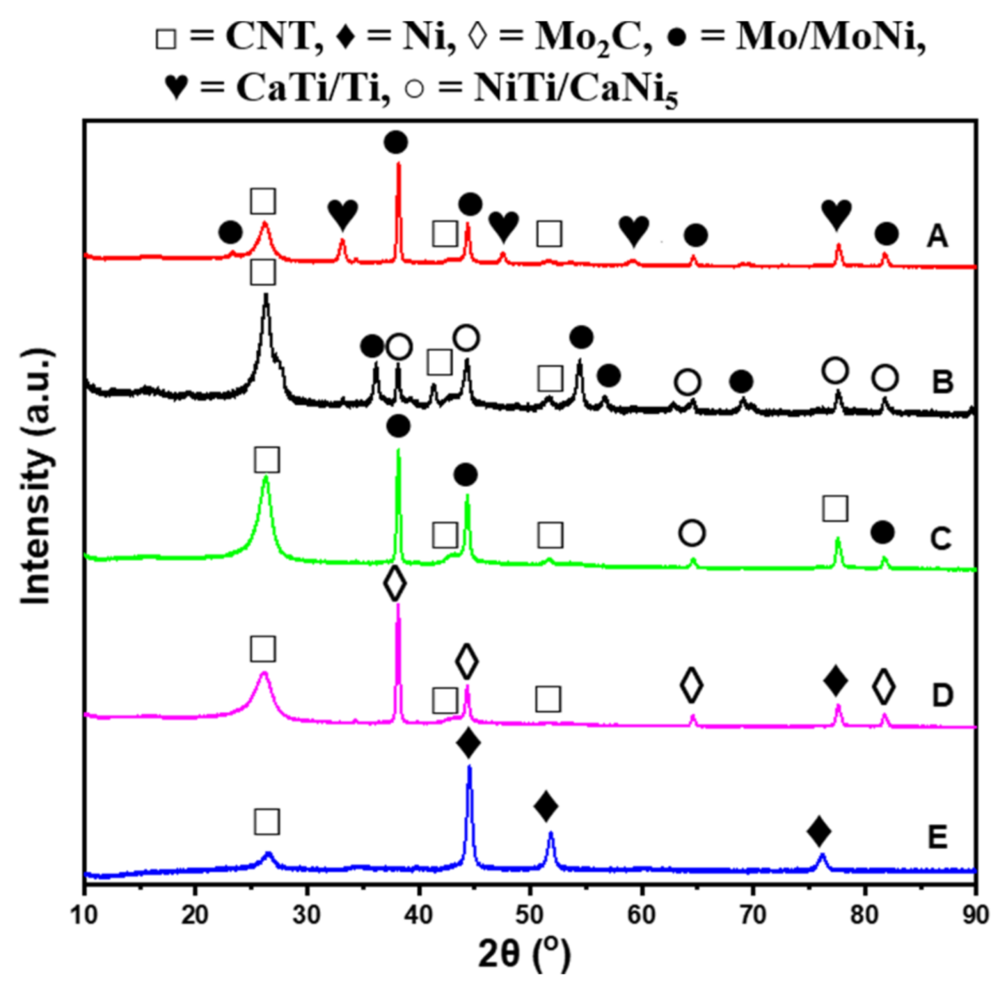
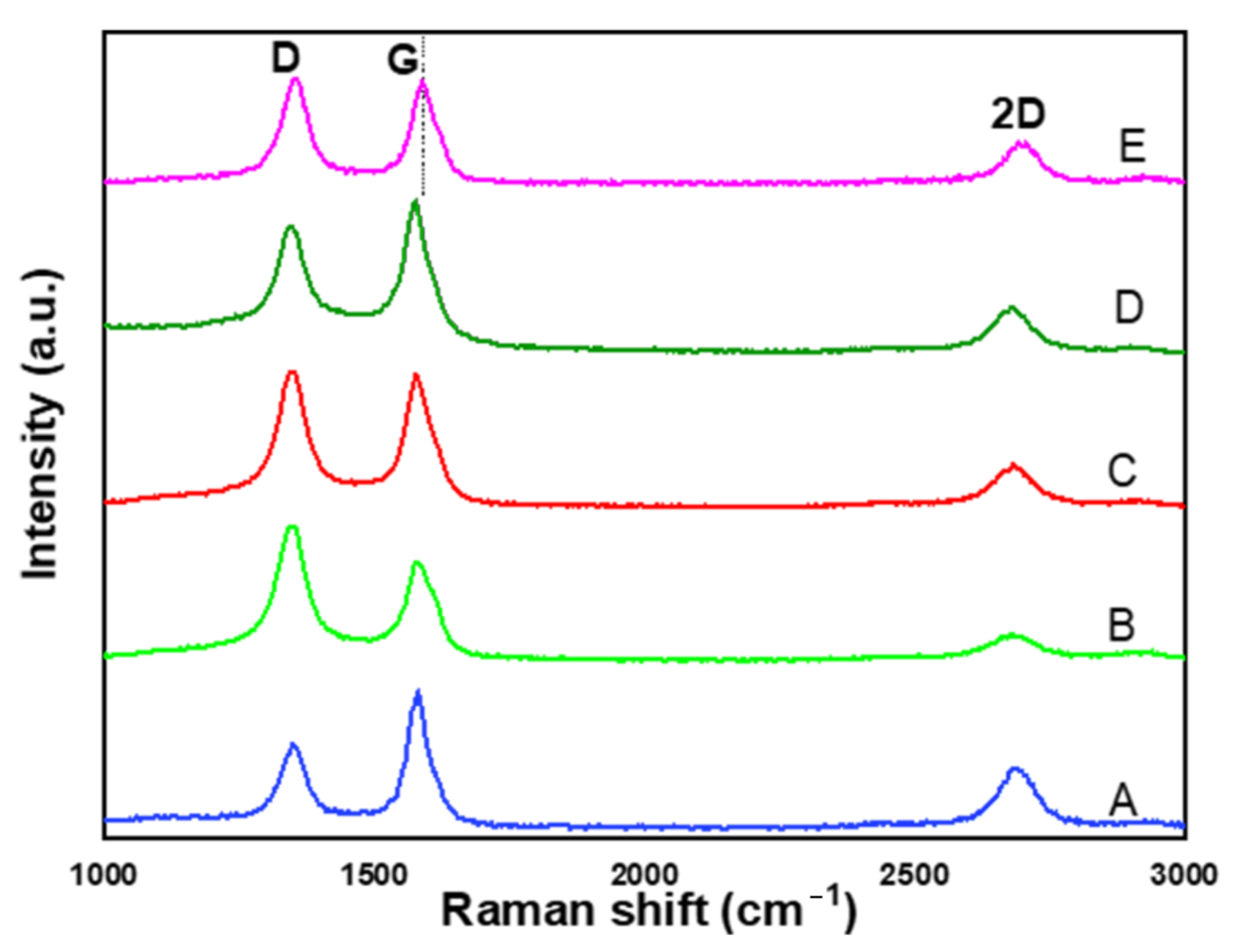
2.4. Effect of Different Supports on the Purity and Graphitization Degree of CNTs

Raman analysis was performed to evaluate the purity (crystallinity), structure, and graphitization degree of MWCNTs deposited over supported and unsupported NiMo catalysts. Figure 7 displayed Raman spectra of as-synthesized MWCNTs. The D-band at around 1352 cm−1 is ascribed to the breathing vibrations of sp3 hybridized carbon from defective or amorphous (non-crystalline) carbon in MWCNTs, while the G-band at around 1580 cm−1 is caused by the tangential vibrations of sp2 hybridized carbon atoms of graphite layers. However, deviation in the G-band (dotted lines), as shown in Figure 8E, at around 1590.8 cm−1 could be attributed to a change in the structural nature of the nanotubes [51]; this is in good agreement with the XRD and TGA results. The shoulder on the right side of the G-band in Figure 8B could be attributed to the increase in the disordered graphite structure and/or variation in the pattern (transverse or longitudinal) mode in the nanotubes’ direction [52]. Again, deconvolution was performed to reveal the position of hidden/overlapped peaks [53] (see the deconvoluted Raman spectra in Supplemenary Materials Figure S2). The 2D band is associated with two-phonon, second-order scattering processes and is an indicator of the increasing defect density of CNTs [54]. The peak intensity ratio IG/ID is used to determine the graphitization degree of graphene planes [55], where a higher IG/ID ratio is an indicator of a higher degree of structural ordering and fewer defects inside the graphene sheet, while higher ID/IG suggests more defects in CNTs [24,56]. As shown in Figure 8 and Table 3, CNTNiMo/CaTiO3 possesses more graphitic CNTs with fewer defects and/or less amorphous carbon, while CNTNiMo had the most defective CNTs and more amorphous carbon within its graphite sheets—this result is consistent with the obtained TGA results.
The stability of carbon samples during oxidation is associated with the degree of crystallinity of CNTs and is linked to the existence of a purer tube shell and fewer defects at the ends of nanotubes. Generally, more thermally stable CNTs suggests higher structural ordering and a lower number of defects [12]. As could be observed from the derivative TGA plot in Figure 7B, the oxidation peaks of CNTs synthesized from supported NiMo catalysts shifted to higher temperatures, suggesting that the presence of the support in the NiMo parent catalyst resulted in increased thermal stability and graphitization degree of all as-produced MWCNTs. Hence, MWCNTs deposited over NiMo/CaTiO3 (CNTNiMo/CaTiO3) showed the most thermally stable MWCNTs at 629 °C, while CNTNiMo, CNTNiMo/CaO, CNTNiMo/TiO2, and CNTNiMo/MgO displayed thermally stable MWCNTs at 603 °C, 601 °C, 606 °C, and 591 °C, respectively.
To further elucidate the phase structure and crystallinity of synthesized CNTs over supported and unsupported NiMo catalysts, XRD analysis was carried out as shown in Figure 6. Diffraction peaks of CNTs (PDF 00-058-1638) detected at 2θ = 26.28°, which corresponds to the (002) diffraction plane, were obtained for all MWCNTs deposited on the surfaces of supported and unsupported NiMo catalysts. Other diffraction planes of CNTs were detected at 2θ = 43°, 53.6°, and 77.5°, which corresponds to (100), (004), and (110) planes, respectively. From the XRD patterns, some other graphite peaks were obtained (PDF 00-041-1487, PDF 01-075-1621, PDF 00-056-0159, and PDF 01-073-598), most of which overlapped with CNT peaks. It is worth mentioning that for CNTNiMo/MgO, four (4) diffraction peaks typical of Mo2C (PDF 01-071-6028) were obtained, as shown in Figure 6D. Such peaks (Mo2C), as reported by many researchers [23,48,57], are instrumental in the growth of CNTs. The (100) peak, which reflects the existence of in-plane regularity and curvature within the graphene layers [58], was absent in CNTNiMo. This could be the reason for the shoulder in Figure 7B emanating from the different wave modes present within the graphene layers. The inter-planar distance, d(002)—that is, the distance between graphene layers—is used to relate the regularity between graphene layers and it is a measure of the graphitization degree of nanotubes [45]. The interlayer orbital interaction results in conductivity of the graphite and the presence of impurities located between graphene layers could result in structural roughness of CNTs [58]. All synthesized nanotubes have interlayer spacing between the graphene layers that is almost similar to the theoretical (0.34 nm) graphene layer spacing for MWCNTs [59], as shown in Table 3. As could be observed, CNTNiMo showed an interlayer distance d(002) value of 0.335 nm, which is typical of graphite, which indicates a related weak interaction between different tube (graphene) walls in MWCNTs [59,60]. CNTNiMo/CaTiO3 depicted a more ordered interlayer arrangement than CNTNiMo/CaO, CNTNiMo/MgO, and CNTNiMo/TiO2. These results correlate with the TGA and Raman results.
The TEM images of the spent catalysts before purification are depicted in Figure 9, and their corresponding Ni crystallite sizes were obtained from XRD analysis. In addition, the average Ni particle size distributions obtained from TEM analysis using ImageJ software are given in Table 4. The XRD data showed that the Ni crystallite size in the unsupported NiMo catalyst was almost double (2 times) the crystallite size of NiO obtained for the calcined NiMo catalyst (see Table 1), suggesting that the Ni particles are thermally unstable during in-situ reduction and at CNT synthesis temperatures. These observations are supported by the report of Ni et al. [41], where Ni catalyst particle size was adversely affected at temperatures between 500 and 540 °C, resulting in low quality in the crystallinity of CNTs. For all supported NiMo catalysts, after in-situ reduction and subsequent CNT synthesis, there was no obvious change in Ni crystallite size or the average particle size distribution of the active phase. This indicates that Ni particles are thermally stable under reductive and synthesis temperatures due to the stabilizing effect of the support. Comparing peaks for residual catalysts in Figure 6, it could be observed that peaks in NiMo-supported catalysts clearly become significantly weaker, demonstrating that the degree of dispersion of the metal active sites is improved by reduction treatment, which resulted in decreased particle size in the catalyst and subsequent better activity.

3. Materials and Methods

3.1. Materials

Waste PP (e.g., food containers for household use) was obtained from the refuse deposition/collection center within the Doornfontein campus of the University of Johannesburg (Johannesburg, Gauteng, South Africa). Surface paint designs were cleaned with acetone in order to remove the painted design from the surfaces of obtained waste PP materials. Thereafter, waste PP was washed, dried, and cut into smaller sizes using a pair of scissors.
The following reagents were utilized in the preparation of catalysts: metal precursors from their salts used were of analytical grade—nickel (II) nitrate hexahydrate (99%), ammonium molybdate tetrahydrate (99%), magnesium nitrate hexahydrate (99%), calcium carbonate (all reagents were obtained from Associated Chemical Enterprises (Pty) Limited, Johannesburg, South Africa); titanium (IV) isopropoxide (TTIP) (97%) (provided by Sigma-Aldrich Ltd., Johannesburg, South Africa); foaming agent—citric acid anhydrous, AR (supplied by Rochelle Chemicals & Laboratory Equipment C.C.); solvents—ethanol (70%) and distilled water. All reagents were used as supplied without additional purification.

3.2. Catalyst Preparation

The sol–gel method was employed in the preparation of catalysts following the method reported by Bajad et al. [5], with some modifications. Metal loadings with molar ratios 5/0.1/1 were maintained for the Ni/Mo/M catalyst (where M is the corresponding metal content of metal oxide or mixed metal oxide support). The same ratio was maintained for all catalysts being investigated. Furthermore, for comparison, an unsupported bimetallic Ni-Mo catalyst was also prepared using a similar Ni/Mo metal loading with molar ratio 5/0.1. For example, to prepare the NiMo/MgO catalyst, a calculated amount of Mg(NO3)2.6H2O was firstly dispersed in ethanol. Then, known quantities of Ni(NO3)2.6H2O and (NH4)6Mo7O24.4H2O were dissolved in distilled water and then poured into the Mg(NO3)2.6H2O solution. Subsequently, 4.0 g of anhydrous citric acid was added into the mixture and all content vigorously stirred using a magnetic stirrer at 60 °C for 6 h. The produced gel was dried overnight at 100 °C in an oven. Similar procedure and molar ratios were maintained for CaO- and TiO2-supported Ni-Mo catalysts. The CaTiO3-supported Ni-Mo catalyst was prepared analogously to the procedure described in our previous study [25]. Preparation protocol for all catalysts is shown in Table 5. All resultant oven-dried green products were ground to powder using an agate mortar and pestle, followed by calcination in air at 600 °C for 4 h to remove organic and inorganic matrix and obtain the desired constituent metal oxide system. Afterwards, calcined catalysts were sieved to particle sizes in the range of 50–180 microns and stored for further use. Obtained catalysts were denoted as NiMo/MgO, NiMo/CaO, NiMo/TiO2, and NiMo/CaTiO3.

3.3. Synthesis of CNTs

The production of CNTs from waste PP was carried out in a single-stage CVD reactor, as shown in Supplementary Materials Figure S1, according to the procedure already described in detail elsewhere [61]. Around 0.5 g of calcined catalyst was distributed evenly on a quartz boat placed at the center of the reactor. The furnace was ramped at 10 °C/min and was heated to a growth temperature of 700 °C. When the set temperature was reached, the catalyst was reduced in-situ for 1 h to obtain the catalyst in its metallic state under H2/Ar gas mixtures at gas flow of 110 mL/min. Afterwards, the boat containing around 1.0 g of waste PP as a carbon source was introduced some centimeters away (relatively low-temperature region) from the position of the boat containing the catalyst and the growth of carbon nanomaterial was allowed for 0.5 h. Thereafter, the setup was cooled down overnight under an argon atmosphere. Each experiment was repeated for accuracy of results and repeatability. The yield of CNT deposits on each of the catalysts was obtained based on the mass of feedstock (polymer used) using Equation (1), as described elsewhere [25]:
CNTs   Yield   % = mass   of   carbon   product     mass   of   catalyst   used mass   of   polymer   used × 100   %
All grown CNTs were labeled according to the catalyst on which they were deposited, as shown in Table 3.

3.4. Characterization of Catalysts

Both surface and internal morphologies of catalysts were obtained using a VEGA 3 TESCAN scanning electron microscope (SEM) (TESCAN, Brno, Czech Republic) attached to an energy-dispersive X-ray spectroscope and JEM-2100 transmission electron microscope (TEM) (JEOL, Tokyo, Japan), respectively. Selected area electron diffraction (SAED) patterns of all catalysts were also acquired on TEM. Average particle size distributions of catalyst were obtained from the TEM images using ImageJ software.
Phase structures of all catalysts under study were obtained using the Rigaku Ultima 1V X-Ray Diffractometer (RIGAKU, Tokyo, Japan) operated at 40 kV and 30 mA using Cu Kα radiation (λ = 1.54 Å); samples were scanned at 2θ range of 10° to 90°. Peaks were identified and matched using PDXL software.
N2 physisorption analysis at −196 °C was carried out using Micromeritics TriStar II Plus (Micromeritics, Norcross, GA, USA) to check for the Brunauer–Emmett–Teller (BET) surface area and surface properties of all catalysts under study.
The reducibility of all calcined catalysts was determined using the H2-temperature-programmed reduction technique (H2-TPR). H2 consumption by the metallic oxide part of all catalysts was tracked by a thermal conductivity detector (TCD) using an in-house built instrument. Precisely, 0.1 g of each catalyst sample was degassed under helium at 300 °C for 60 minutes and afterwards heated to 800 °C under 10 vol% H2/90 vol% Ar gas mixture for 2 h [62].

3.5. Characterization of CNTs

Microstructures of as-grown carbon on the surface of each catalyst were acquired using a JEM-2100 transmission electron microscope (TEM) (JEOL, Tokyo, Japan). Additionally, the outer diameter distribution of all obtained CNTs was obtained using ImageJ software.
Temperature-programmed oxidation (TPO) via TGA (thermogravimetric analysis) HITACHI STA-7200RV (HITACHI, Tokyo, Japan) was utilized to evaluate the thermal stability of all obtained carbon nanomaterials grown on the surfaces of each catalyst. During analysis, around 5.0 mg of each carbon sample was heated in air with a flow rate of 20 ml/min and ramped at 10 °C/min from 30 °C to 900 °C [15].
Raman spectroscopy of synthesized CNTs was carried out to evaluate their graphitic nature/quality; spectrograms were obtained at a Raman shift range of 1000 to 3000 cm−1 at 532 nm wavelength using a WITec focus innovations Raman Spectrometer (WITec, Ulm, Germany).
The crystallinity as well as morphology of all obtained carbon nanomaterials deposited on each catalyst were determined by XRD using the Rigaku Ultima 1V X-ray diffractometer (XRD) (RIGAKU, Tokyo, Japan) operated with Cu Kα (λ = 1.54 Å) radiation, in the 2θ range of 10° to 90°.

4. Conclusions

The effect of different catalyst supports in an NiMo catalyst during the production of CNTs has been demonstrated and reported in this article. All supported catalysts studied and reported displayed moderate metal–support interaction (i.e., the interaction was not too strong or too weak), attributable to the stabilizing effect of the supports, thereby enhancing the activities of the catalysts, as supported by the TPR and XRD results. Supports are instrumental to obtaining higher-yield CNTs. For example, the use of a supported NiMo/CaTiO3 catalyst displayed the highest carbon yield of around 40.0% with good-quality and well-aligned CNTs, while unsupported NiMo displayed the lowest yield of 18.4%. The difference in the yield of deposited CNTs over supported and unsupported NiMo catalysts could be attributed to the large percentage of active metal nanoparticles that were not utilized in the nucleation and growth of CNTs in the unsupported NiMo catalyst, as showcased by the TPO results. The use of the NiMo/CaTiO3 catalyst was more effective in the formation of higher-yield and better graphitized CNTs than using NiMo/TiO2, NiMo/CaO, and NiMo/MgO catalysts. The outstanding performance of the NiMo/CaTiO3 catalyst utilized in growing CNTs during the decomposition of waste PP could be correlated to the prevalence of metastable phases present and the large, ordered pore sizes of the catalyst, which makes them less prone to catalyst deactivation, resulting in improved dispersion and activity compared to other catalysts. Therefore, the catalytic performance of the NiMo catalyst strongly depends on the type of support material employed during CNT growth from waste PP.

Supplementary Materials

The following are available online at https://www.mdpi.com/article/10.3390/catal11060692/s1: Figure S1: Nitrogen adsorption/desorption isotherms of all prepared NiMo supported and unsupported catalysts, Figure S2: Raman spectra of as-synthesized CNTs with deconvoluted spectra are available as supplementary information for the article.

Author Contributions

Conceptualization, H.U.M., M.O.D. and K.M.; methodology, M.A.M.; formal analysis, H.U.M.; investigation, H.U.M.; resources, K.M.; writing—original draft preparation, H.U.M.; writing—review and editing, M.O.D., H.U.M. and M.A.M.; supervision, K.M., M.A.M. and M.O.D. All authors have read and agreed to the published version of the manuscript.

Funding

This research was funded by the UNIVERSITY OF JOHANNESBURG, South Africa, under the Global Excellence Stature, Fourth Industrial Revolution (GES 4IR) scholarship.

Conflicts of Interest

The authors declare no conflict of interest.

References

  1. Gahleitner, M.; Paulik, C. Polypropylene and other Polyolefins. In Brydson’s Plastics Materials; Elsevier Ltd.: Kidlington, UK, 2017; pp. 279–309. ISBN 9780323358248. [Google Scholar]
  2. Maddah, H.A. Polypropylene as a promising plastics: A Review. Am. J. Polym. Sci. 2016, 6, 1–11. [Google Scholar] [CrossRef]
  3. Posch, D.W. Polyolefins. In Applied Plastics Engineering Handbook; Elsevier Inc.: Kidlington, UK, 2017; pp. 27–53. ISBN 9780323390408. [Google Scholar]
  4. Singh, N.; Hui, D.; Singh, R.; Ahuja, I.; Feo, L.; Fraternali, F. Recycling of plastic solid waste: A state of art review and future applications. Compos. Part B Eng. 2017, 115, 409–422. [Google Scholar] [CrossRef]
  5. Bajad, G.S.; Tiwari, S.K.; Vijayakumar, R. Synthesis and characterization of CNTs using polypropylene waste as precursor. Mater. Sci. Eng. B 2015, 194, 68–77. [Google Scholar] [CrossRef]
  6. Gong, J.; Liu, J.; Wan, D.; Chen, X.; Wen, X.; Mijowska, E.; Jiang, Z.; Wang, Y.; Tang, T. Catalytic carbonization of polypropylene by the combined catalysis of activated carbon with Ni2O3 into carbon nanotubes and its mechanism. Appl. Catal. A Gen. 2012, 449, 112–120. [Google Scholar] [CrossRef]
  7. Nahil, M.A.; Wu, C.; Williams, P.T. Influence of metal addition to Ni-based catalysts for the co-production of carbon nanotubes and hydrogen from the thermal processing of waste polypropylene. Fuel Process. Technol. 2015, 130, 46–53. [Google Scholar] [CrossRef]
  8. Cai, N.; Li, X.; Xia, S.; Sun, L.; Hu, J.; Bartocci, P.; Fantozzi, F.; Williams, P.T.; Yang, H.; Chen, H. Pyrolysis-catalysis of different waste plastics over Fe/Al2O3 catalyst: High-value hydrogen, liquid fuels, carbon nanotubes and possible reaction mechanisms. Energy Convers. Manag. 2021, 229, 113794. [Google Scholar] [CrossRef]
  9. Deng, J.; You, Y.; Sahajwalla, V.; Joshi, R.K. Transforming waste into carbon-based nanomaterials. Carbon 2016, 96, 105–115. [Google Scholar] [CrossRef]
  10. Raman and TGA Study of Carbon Nanotubes Synthesized Over Mo/Fe Catalyst on Aluminium Oxide, Calcium Carbonate and Magnesium Oxide Support. Chem. Sci. Trans. 2013, 2, 1160–1173. [CrossRef] [Green Version]
  11. Yeoh, W.-M.; Lee, K.-Y.; Chai, S.-P.; Lee, K.-T.; Mohamed, A.R. Effective synthesis of carbon nanotubes via catalytic decomposition of methane: Influence of calcination temperature on metal–support interaction of Co–Mo/MgO catalyst. J. Phys. Chem. Solids 2013, 74, 1553–1559. [Google Scholar] [CrossRef]
  12. Yao, D.; Wu, C.; Yang, H.; Zhang, Y.; Nahil, M.A.; Chen, Y.; Williams, P.T.; Chen, H. Co-production of hydrogen and carbon nanotubes from catalytic pyrolysis of waste plastics on Ni-Fe bimetallic catalyst. Energy Convers. Manag. 2017, 148, 692–700. [Google Scholar] [CrossRef]
  13. Munnik, P.; De Jongh, P.E.; De Jong, K.P. Recent Developments in the Synthesis of Supported Catalysts. Chem. Rev. 2015, 115, 6687–6718. [Google Scholar] [CrossRef]
  14. Shah, K.A.; Malik, M.A.; Andrabi, S.M.A.; Shah, M.A. A Study of Catalyst Preparation Methods for Synthesis of Carbon Nanotubes. Chem. Sci. Trans. 2016, 5, 1–7. [Google Scholar] [CrossRef]
  15. Lobiak, E.; Shlyakhova, E.; Bulusheva, L.; Plyusnin, P.; Shubin, Y.; Okotrub, A. Ni–Mo and Co–Mo alloy nanoparticles for catalytic chemical vapor deposition synthesis of carbon nanotubes. J. Alloys Compd. 2015, 621, 351–356. [Google Scholar] [CrossRef]
  16. Kubička, D.; Horáček, J.; Setnička, M.; Bulánek, R.; Zukal, A.; Kubičková, I. Effect of support-active phase interactions on the catalyst activity and selectivity in deoxygenation of triglycerides. Appl. Catal. B Environ. 2014, 145, 101–107. [Google Scholar] [CrossRef]
  17. Li, G.; Tan, S.; Song, R.; Tang, T. Synergetic Effects of Molybdenum and Magnesium in Ni–Mo–Mg Catalysts on the One-Step Carbonization of Polystyrene into Carbon Nanotubes. Ind. Eng. Chem. Res. 2017, 56, 11734–11744. [Google Scholar] [CrossRef]
  18. Ashik, U.; Daud, W.W.; Hayashi, J.-I. A review on methane transformation to hydrogen and nanocarbon: Relevance of catalyst characteristics and experimental parameters on yield. Renew. Sustain. Energy Rev. 2017, 76, 743–767. [Google Scholar] [CrossRef]
  19. Ahmad, S.; Liao, Y.; Hussain, A.; Zhang, Q.; Ding, E.-X.; Jiang, H.; Kauppinen, E.I. Systematic investigation of the catalyst composition effects on single-walled carbon nanotubes synthesis in floating-catalyst CVD. Carbon 2019, 149, 318–327. [Google Scholar] [CrossRef]
  20. Najafishirtari, S.; Guglieri, C.; Marras, S.; Scarpellini, A.; Brescia, R.; Prato, M.; Righi, G.; Franchini, A.; Magri, R.; Manna, L.; et al. Metal-support interaction in catalysis: The influence of the morphology of a nano-oxide domain on catalytic activity. Appl. Catal. B Environ. 2018, 237, 753–762. [Google Scholar] [CrossRef]
  21. Doustan, F.; Pasha, M.A. Growth of carbon nanotubes over Fe-Co and Ni-Co catalysts supported on different phases of TiO2 substrate by thermal CVD. Full-Nanotub. Carbon Nanostruct. 2016, 24, 25–33. [Google Scholar] [CrossRef]
  22. Zhuo, C.; Levendis, Y.A. Upcycling waste plastics into carbon nanomaterials: A review. J. Appl. Polym. Sci. 2014, 131, 1–14. [Google Scholar] [CrossRef]
  23. Bajad, G.; Guguloth, V.; Vijayakumar, R.P.; Bose, S. Conversion of plastic waste into CNTs using Ni/Mo/MgO catalyst—An optimization approach by mixture experiment. Full-Nanotub. Carbon Nanostruct. 2015, 24, 162–169. [Google Scholar] [CrossRef]
  24. Zhang, Q.; Liu, Y.; Hu, L.; Qian, W.-Z.; Luo, G.-H.; Wei, F. Synthesis of thin-walled carbon nanotubes from methane by changing the Ni/Mo ratio in a Ni/Mo/MgO catalyst. New Carbon Mater. 2008, 23, 319–325. [Google Scholar] [CrossRef]
  25. Modekwe, H.U.; Mamo, M.A.; Daramola, M.O.; Moothi, K. Catalytic Performance of Calcium Titanate for Catalytic Decomposition of Waste Polypropylene to Carbon Nanotubes in a Single-Stage CVD Reactor. Catalysts 2020, 10, 1030. [Google Scholar] [CrossRef]
  26. Liu, H.; Seaton, N. Determination of the connectivity of porous solids from nitrogen sorption measurements—III. Solids containing large mesopores. Chem. Eng. Sci. 1994, 49, 1869–1878. [Google Scholar] [CrossRef]
  27. Sing, K.S.; Williams, R.T. Physisorption Hysteresis Loops and the Characterization of Nanoporous Materials. Adsorpt. Sci. Technol. 2004, 22, 773–782. [Google Scholar] [CrossRef]
  28. Li, M.; Song, J.; Yue, F.; Pan, F.; Yan, W.; Hua, Z.; Li, L.; Yang, Z.; Li, L.; Wen, G.; et al. Complete Hydrodesulfurization of Dibenzothiophene via Direct Desulfurization Pathway over Mesoporous TiO2-Supported NiMo Catalyst Incorporated with Potassium. Catalysts 2019, 9, 448. [Google Scholar] [CrossRef] [Green Version]
  29. De Boer, J.; Heuvel, A.V.D.; Linsen, B. Studies on pore systems in catalysts IV. The two causes of reversible hysteresis. J. Catal. 1964, 3, 268–273. [Google Scholar] [CrossRef]
  30. Subbotin, A.N.; Subbotina, I.R.; Golosman, E.Z. Hysteresis phenomena in heterogeneous exothermal catalytic reactions and methods for decreasing the overheating of catalyst nanoclusters. Mendeleev Commun. 2015, 25, 216–218. [Google Scholar] [CrossRef]
  31. Pudukudy, M.; Yaakob, Z.; Kadier, A.; Takriff, M.S.; Hassan, N.S.M. One-pot sol–gel synthesis of Ni/TiO2 catalysts for methane decomposition into COx free hydrogen and multiwalled carbon nanotubes. Int. J. Hydrogen Energy 2017, 42, 16495–16513. [Google Scholar] [CrossRef]
  32. Zhuang, Z.; Giles, S.A.; Zheng, J.; Jenness, G.R.; Caratzoulas, S.; Vlachos, D.G.; Yan, Y. Nickel supported on nitrogen-doped carbon nanotubes as hydrogen oxidation reaction catalyst in alkaline electrolyte. Nat. Commun. 2016, 7, 10141. [Google Scholar] [CrossRef] [Green Version]
  33. Nairan, A.; Zou, P.; Liang, C.; Liu, J.; Wu, D.; Liu, P.; Yang, C. NiMo Solid Solution Nanowire Array Electrodes for Highly Efficient Hydrogen Evolution Reaction. Adv. Funct. Mater. 2019, 29, 1903747. [Google Scholar] [CrossRef]
  34. Fan, X.; Liu, D.; Zhao, Z.; Li, J.; Liu, J. Influence of Ni/Mo ratio on the structure-performance of ordered mesoporous Ni-Mo-O catalysts for oxidative dehydrogenation of propane. Catal. Today 2020, 339, 67–78. [Google Scholar] [CrossRef]
  35. Méndez, F.J.; Bravo-Ascención, G.; González-Mota, M.; Puente-Lee, I.; Bokhimi, X.; Klimova, T.E. NiMo catalysts supported on Al, Nb, Ti or Zr-containing MCM-41 for dibenzothiophene hydrodesulfurization. Catal. Today 2020, 349, 217–227. [Google Scholar] [CrossRef]
  36. Wang, J.; Shen, B.; Lan, M.; Kang, D.; Wu, C. Carbon nanotubes (CNTs) production from catalytic pyrolysis of waste plastics: The influence of catalyst and reaction pressure. Catal. Today 2020, 351, 50–57. [Google Scholar] [CrossRef]
  37. Damyanova, S.; Spojakina, A.; Jiratova, K. Effect of mixed titania-alumina supports on the phase composition of NiMo/TiO2Al2O3 catalysts. Appl. Catal. A Gen. 1995, 125, 257–269. [Google Scholar] [CrossRef]
  38. González-Cortés, S.L.; Aray, I.; Rodulfo-Baechler, S.M.A.; Lugo, C.A.; Del Castillo, H.L.; Loaiza-Gil, A.; Imbert, F.E.; Figueroa, H.; Pernía, W.; Rodríguez, A.; et al. On the structure and surface properties of NiO/MgO–La2O3 catalyst: Influence of the support composition and preparation method. J. Mater. Sci. 2007, 42, 6532–6540. [Google Scholar] [CrossRef]
  39. Salinas, D.A.; Marchena, C.L.; Pierella, L.B.; Pecchi, G. Catalytic oxidation of 2-(methylthio)-benzothiazole on alkaline earth titanates, ATiO3 (A = Ca, Sr, Ba). Mol. Catal. 2017, 438, 76–85. [Google Scholar] [CrossRef]
  40. Shen, Y.; Lua, A.C. Sol–gel synthesis of Ni and Ni supported catalysts for hydrogen production by methane decomposition. RSC Adv. 2014, 4, 42159–42167. [Google Scholar] [CrossRef]
  41. Ni, L.; Kuroda, K.; Zhou, L.-P.; Kizuka, T.; Ohta, K.; Matsuishi, K.; Nakamura, J. Kinetic study of carbon nanotube synthesis over Mo/Co/MgO catalysts. Carbon 2006, 44, 2265–2272. [Google Scholar] [CrossRef] [Green Version]
  42. Liu, X.; Zhang, Y.; Nahil, M.A.; Williams, P.T.; Wu, C. Development of Ni- and Fe- based catalysts with different metal particle sizes for the production of carbon nanotubes and hydrogen from thermo-chemical conversion of waste plastics. J. Anal. Appl. Pyrolysis 2017, 125, 32–39. [Google Scholar] [CrossRef]
  43. Takenaka, S.; Ishida, M.; Serizawa, M.; Tanabe, A.E.; Otsuka, K. Formation of Carbon Nanofibers and Carbon Nanotubes through Methane Decomposition over Supported Cobalt Catalysts. J. Phys. Chem. B 2004, 108, 11464–11472. [Google Scholar] [CrossRef]
  44. Wang, B.; Yang, Y.; Li, L.-J.; Chen, Y. Effect of different catalyst supports on the (n,m) selective growth of single-walled carbon nanotube from Co–Mo catalyst. J. Mater. Sci. 2009, 44, 3285–3295. [Google Scholar] [CrossRef]
  45. Cao, A.; Xu, C.; Liang, J.; Wu, D.; Wei, B. X-ray diffraction characterization on the alignment degree of carbon nanotubes. Chem. Phys. Lett. 2001, 344, 13–17. [Google Scholar] [CrossRef]
  46. Che, B.D.; Nguyen, B.Q.; Nguyen, L.-T.T.; Nguyen, H.T.; Nguyen, V.Q.; Van Le, T.; Nguyen, N.H. The impact of different multi-walled carbon nanotubes on the X-band microwave absorption of their epoxy nanocomposites. Chem. Central J. 2015, 9, 1–13. [Google Scholar] [CrossRef] [Green Version]
  47. Lehman, J.H.; Terrones, M.; Mansfield, E.; Hurst, K.E.; Meunier, V. Evaluating the characteristics of multiwall carbon nanotubes. Carbon 2011, 49, 2581–2602. [Google Scholar] [CrossRef]
  48. Xu, X.; Huang, S.; Yang, Z.; Zou, C.; Jiang, J.; Shang, Z. Controllable synthesis of carbon nanotubes by changing the Mo content in bimetallic Fe–Mo/MgO catalyst. Mater. Chem. Phys. 2011, 127, 379–384. [Google Scholar] [CrossRef]
  49. Mansfield, E.; Kar, A.; Hooker, S.A. Applications of TGA in quality control of SWCNTs. Anal. Bioanal. Chem. 2010, 396, 1071–1077. [Google Scholar] [CrossRef]
  50. Charisiou, N.D.; Douvartzides, S.L.; Siakavelas, G.I.; Tzounis, L.; Sebastian, V.; Stolojan, V.; Hinder, S.J.; Baker, M.A.; Polychronopoulou, K.; Goula, M.A. The Relationship between Reaction Temperature and Carbon Deposition on Nickel Catalysts Based on Al2O3, ZrO2 or SiO2 Supports during the Biogas Dry Reforming Reaction. Catalysts 2019, 9, 676. [Google Scholar] [CrossRef] [Green Version]
  51. Dresselhaus, M.; Dresselhaus, G.; Saito, R.; Jorio, A. Raman spectroscopy of carbon nanotubes. Phys. Rep. 2005, 409, 47–99. [Google Scholar] [CrossRef]
  52. Yusof, Y.; Zaidi, M.I.; Johan, M.R. Enhanced Structural, Thermal, and Electrical Properties of Multiwalled Carbon Nanotubes Hybridized with Silver Nanoparticles. J. Nanomater. 2016, 2016, 6141496. [Google Scholar] [CrossRef]
  53. Liu, H.; Yan, L.; Chang, Y.; Fang, H.; Zhang, T. Spectral Deconvolution and Feature Extraction with Robust Adaptive Tikhonov Regularization. IEEE Trans. Instrum. Meas. 2013, 62, 315–327. [Google Scholar] [CrossRef]
  54. Pelech, I.; Narkiewicz, U.; Kaczmarek, A.; Jedrzejewska, A. Preparation and characterization of multi-walled carbon nano-tubes grown on transition metal catalysts. Polish J. Chem. Technol. 2014, 16, 117–122. [Google Scholar] [CrossRef] [Green Version]
  55. Gong, J.; Feng, J.; Liu, J.; Jiang, Z.; Chen, X.; Mijowska, E.; Wen, X.; Tang, T. Catalytic carbonization of polypropylene into cup-stacked carbon nanotubes with high performances in adsorption of heavy metallic ions and organic dyes. Chem. Eng. J. 2014, 248, 27–40. [Google Scholar] [CrossRef]
  56. Gong, J.; Liu, J.; Chen, X.; Jiang, Z.; Wen, X.; Mijowska, E.; Tang, T. Converting real-world mixed waste plastics into porous carbon nanosheets with excellent performance in the adsorption of an organic dye from wastewater. J. Mater. Chem. A 2015, 3, 341–351. [Google Scholar] [CrossRef]
  57. Li, Y.; Zhang, X.; Tao, X.; Xu, J.; Huang, W.; Luo, J.; Luo, Z.; Li, T.; Liu, F.; Bao, Y.; et al. Mass production of high-quality multi-walled carbon nanotube bundles on a Ni/Mo/MgO catalyst. Carbon 2005, 43, 295–301. [Google Scholar] [CrossRef]
  58. Das, R.; Hamid, S.B.A.; Ali, E.; Ramakrishna, S.; Yongzhi, W. Carbon Nanotubes Characterization by X-ray Powder Diffraction—A Review. Curr. Nanosci. 2014, 11, 23–35. [Google Scholar] [CrossRef] [Green Version]
  59. Wang, S.; Conant, G.C.; Ou, R.; Beerntsen, B.T. Cloning and characterization of the peptidoglycan recognition protein genes in the mosquito, Armigeres subalbatus (Diptera: Culicidae). J. Med Èntomol. 2012, 49, 656–671. [Google Scholar] [CrossRef]
  60. Kharissova, O.V.; Kharisov, B.I. Variations of interlayer spacing in carbon nanotubes. RSC Adv. 2014, 4, 30807–30815. [Google Scholar] [CrossRef]
  61. Modekwe, H.; Mamo, M.; Moothi, K.; Daramola, M. Synthesis of bimetallic NiMo/MgO catalyst for catalytic conversion of waste plastics (polypropylene) to carbon nanotubes (CNTs) via chemical vapour deposition method. Mater. Today Proc. 2021, 38, 549–552. [Google Scholar] [CrossRef]
  62. Iloy, R.A.; Jalama, K. Effect of Operating Temperature, Pressure and Potassium Loading on the Performance of Silica-Supported Cobalt Catalyst in CO2 Hydrogenation to Hydrocarbon Fuel. Catalysts 2019, 9, 807. [Google Scholar] [CrossRef] [Green Version]
Figure 1. XRD profile of all prepared catalysts: NiMo (A), NiMo/MgO (B), NiMo/CaO (C), NiMo/TiO2 (D), and NiMo/CaTiO3 (E).
Catalysts 11 00692 g001
Figure 2. SEM images of prepared catalysts: NiMo (A); NiMo/MgO (B); NiMo/CaO (C); NiMo/TiO2 (D); and NiMo/CaTiO3 (E).
Catalysts 11 00692 g002
Figure 3. TEM micrographs (AE), SAED pattern (FJ), and particle size distribution (PSD) histograms (KO) of all prepared catalysts: NiMo (A), NiMo/MgO (B), NiMo/CaO (C), NiMo/TiO2 (D), and NiMo/CaTiO3 (E).
Catalysts 11 00692 g003
Figure 4. H2-temperature programmed reduction (TPR) profile of all prepared catalysts: NiMo/CaTiO3 (a), NiMo/TiO2 (b), NiMo/CaO (c), NiMo/MgO (d), and NiMo (e).
Catalysts 11 00692 g004
Figure 5. TEM images (AE) and the corresponding diameter distribution histogram (FJ) of as-deposited nanomaterial on the surface of each catalyst: CNTNiMo/MgO (A); CNTNiMo/CaO (B); CNTNiMo/TiO2 (C); CNTNiMo/CaTiO3 (D); and CNTNiMo (E).
Catalysts 11 00692 g005
Figure 6. Phase structures of synthesized CNTs over different catalysts: (A) CNTNiMo/CaTiO3, (B) CNTNiMo/TiO2, (C) CNTNiMo/CaO, (D) CNTNiMo/MgO, and (E) CNTNiMo.
Catalysts 11 00692 g006
Figure 7. Temperature-programmed oxidation (TPO) (A) and derivative TG plot (B) of all deposited CNTs over different catalysts.
Catalysts 11 00692 g007
Figure 8. Raman spectra of synthesized CNTs: (A) CNTNiMo/CaTiO3, (B) CNTNiMo, (C) CNTNiMo/CaO, (D) CNTNiMo/TiO2, and (E) CNTNiMo/MgO.
Catalysts 11 00692 g008
Figure 9. TEM micrographs of spent NiMo catalysts before purification: (A) NiMo, (B) NiMo/MgO, (C) NiMo/CaO, (D) NiMo/TiO2, and (E) NiMo/CaTiO3.
Catalysts 11 00692 g009
Table 1. Textural characteristics of supported and unsupported NiMo catalysts.
CatalystBET Surface Area (m2g−1)Pore Volume (cm3g−1)Pore Size
(nm)
NiO Crystallite Size (nm)
NiMo72.50.34712.07.7
NiMo/MgO56.60.26712.011.8
NiMo/CaO16.00.08514.36.3
NiMo/TiO227.50.0949.05.8
NiMo/CaTiO319.40.12922.311.3
Table 2. Energy-dispersive x-ray spectroscopy (EDS) result of all calcined catalysts.
CatalystWeight (%)
NiMoMgCaTiO
NiMo/MgO44.5110.5316.76--28.20
NiMo/CaO44.5910.97-15.51-28.93
NiMo/TiO244.4010.50--16.0129.09
NiMo/CaTiO341.529.55-15.0214.2919.62
NiMo44.909.00---46.10
Table 3. Properties of as-synthesized MWCNTs deposited on the surfaces of unsupported and supported NiMo catalysts.
SampleCNTs Yield
(%)
CNTs Average
Outer Diameter
(nm)
d(002)
(nm)
Intensity
Ratio
IG/ID
Intensity Ratio ID/IGI(002)
(a.u.)
CNTNiMo18.425.08 ± 7.5380.3350.931.174814
CNTNiMo/MgO33.325.54 ± 6.3970.3390.991.0113,802
CNTNiMo/CaO31.019.36 ± 3.8970.3381.001.0012,499
CNTNiMo/TiO237.022.08 ± 3.4480.3391.070.934871
CNTNiMo/CaTiO340.024.01 ± 4.8900.3401.250.804744
Table 4. Ni crystallite size obtained from XRD and average Ni particle size distribution from TEM analysis of all spent catalysts after reduction and CNT synthesis.
CatalystsNi Average Particle Size of Spent Catalyst (nm)Ni Crystallite Size of Spent Catalyst (nm)
NiMo/MgO15.8–26.011.08
NiMo/CaO6.0–13.07.02
NiMo/TiO213.0–20.06.10
NiMo/CaTiO310.6–17.710.52
NiMo22.0–42.012.65
Table 5. Metal loadings in the preparation protocol for supported and unsupported NiMo catalysts.
CatalystNi
(mol)
Mo
(mol)
Support
(mol)
Corresponding CNTs Notation
NiMo50.1-CNTNiMo
NiMo/MgO50.11CNTNiMo/MgO
NiMo/CaO50.11CNTNiMo/CaO
NiMo/TiO250.11CNTNiMo/TiO2
NiMo/CaTiO350.11CNTNiMo/CaTiO3
Publisher’s Note: MDPI stays neutral with regard to jurisdictional claims in published maps and institutional affiliations.

