A Novel Catalytic Micro-Combustor Inspired by the Nasal Geometry of Reindeer: CFD Modeling and Simulation


1
Istituto di Ricerche sulla Combustione, Consiglio Nazionale delle Ricerche (CNR), Piazzale V. Tecchio 80, 80125 Napoli, Italy
2
Dipartimento di Ingegneria Chimica, dei Materiali e della Produzione Industriale, Università degli Studi di Napoli Federico II, Piazzale V. Tecchio 80, 80125 Napoli, Italy
*
Authors to whom correspondence should be addressed.
Catalysts 2020, 10(6), 606; https://doi.org/10.3390/catal10060606
Submission received: 30 April 2020
/
Revised: 22 May 2020
/
Accepted: 28 May 2020
/
Published: 31 May 2020
(This article belongs to the Special Issue Novel Structured Catalytic Reactors)
Abstract
:A three-dimensional CFD model of a novel configuration of catalytic micro-combustor inspired by the nasal geometry of reindeer was developed using the commercial code ANSYS Fluent 19.0. The thermal behavior of this nature-inspired (NI) configuration was investigated through simulations of lean propane/air combustion performed at different values of residence time (i.e., inlet gas velocity) and (external convective) heat transfer coefficient. Simulations at the same conditions were also run for a standard parallel-channel (PC) configuration of equivalent dimensions. Numerical results show that the operating window of stable combustion is wider in the case of the NI configuration. In particular, the blow-out behavior is substantially the same for the two configurations. Conversely, the extinction behavior, which is dominated by competition between the heat losses towards the external environment and the heat produced by combustion, differs. The NI configuration exhibits a greater ability than the PC configuration to keep the heat generated by combustion trapped inside the micro-reactor. As a consequence, extinction occurs at higher values of residence time and heat transfer coefficient for this novel configuration.
1. Introduction
Hydrocarbon-fueled micro-combustors have been proposed to replace batteries in portable electronic devices [1,2], their main advantage being related to the high gravimetric energy density of hydrocarbons. In addition, micro-combustors/reactors in parallel arrangement can be used as an alternative to conventional devices to achieve an inherently safer operation [3].
The main issue of micro-combustors is thermal management. When reducing the reactor scale from macro to micro, the surface area-to-volume ratio increases. This may lead to an increase of heat losses towards the external environment with respect to the heat generated by combustion, thus reducing the operating window of stable combustion. In order to enlarge the stability limits, the catalytic coating of the walls of the micro-combustor has been proposed. It has been shown that the presence of a catalyst allows for a significant improvement in thermal performance with respect to homogeneous micro-combustors [2]. However, the stability of catalytic micro-combustors still remains an issue [4,5,6,7,8,9].
In order to improve the stability of micro-combustors, several alternative configurations have been proposed. In particular, to enhance the heat recirculation from the hot zones to the cold zones, reverse-flow [10], heat-recirculating [11,12] and Swiss-roll [13,14] micro-reactors were investigated. On the basis of the localization of heat losses, a selective coating of the channels of the micro-combustor has also been proposed, thus saving catalyst: since the main source of heat losses is localized at the external surface of the outer channels, only these channels were coated with the catalyst, whereas the inner channels were left uncoated, being protected from heat losses by the outer ones [15,16,17,18]. It has been shown that, in partially coated configurations, the catalyst can be used essentially as a “pilot” of homogeneous combustion warranting ignition and, at the same time, a relatively higher temperature and, thus, improved stability [15,16,17,18,19].
With the aim of developing more stable catalytic micro-combustors, recently, Kaisare’s group studied a spiral configuration by means of both two-dimensional [20] and three-dimensional [21] CFD simulations. This configuration was obtained by curling up a straight channel into a spiral, thus providing large ratios of internal heat exchange area to external heat loss area. In the spiral micro-reactor, the flow enters the spiral geometry through the inlet at the center and exits tangentially through the outlet. Comparison with the straight channel has shown that the spiral is more stable due to two mechanisms: transverse heat recirculation taking place from hot products to the cold feed between adjacent turns of the spiral, and better protection of the central combustion zone from heat losses [20,21]. The spiral is indeed characterized by a higher temperature and a higher contribution from homogeneous chemistry [21].
In this context, nature can play a significant role in inspiring more energy-efficient equipment. Magnanelli et al. [22] have shown how reindeer can inspire a novel industrial design with high heat efficiency. Indeed, reindeer in the arctic region live under very harsh conditions and may face temperatures below −40 °C. Therefore, in order to survive, conservation of body heat is crucial. The reindeer nasal geometry/mechanism for heat and mass exchange during respiration plays a key role in this respect. The perpendicular section of the reindeer nose has a spiral geometry. Air enters perpendicularly to the spiral and is efficiently and quickly heated.
Inspired by the efficient heat management of the reindeer nasal geometry, we here propose a novel spiral catalytic micro-combustor. To investigate the thermal behavior of this nature-inspired configuration, we developed a three-dimensional CFD model. Simulations of lean propane/air combustion were performed at different values of inlet gas velocity (i.e., residence time) and (external convective) heat transfer coefficient. For the sake of comparison, simulations at the same conditions were also run for a standard parallel-channel (PC) configuration of equivalent dimensions.
2. Results and Discussion
In this section, simulation results obtained for the parallel-channel (PC) configuration and the nature-inspired (NI) configuration are presented and discussed. We start from the results of simulations run at different values of inlet gas velocity, vin (i.e., residence time, τ = length of the reactor/inlet gas velocity—L/vin) (Section 2.1). These results show differences in terms of thermal behavior between the two configurations. The nature of these differences is supposed and, then, confirmed by the results of simulations run at different values of (external convective) heat transfer coefficient, hext (Section 2.2).
2.1. Effect of the Inlet Gas Velocity (i.e., Residence Time)
Figure 1 and Figure 2 show the maps of (top) propane molar fraction and (bottom) temperature as calculated over different cross-sections of the micro-reactor at different values of inlet gas velocity, vin (i.e., residence time, τ), for the parallel-channel (PC) configuration and the nature-inspired (NI) configuration, respectively.
There are aspects common to both configurations. In particular, from the maps of propane molar fraction, it can be seen that, as the inlet gas velocity is increased, the reaction front is progressively shifted downstream until it reaches a condition of non-complete fuel conversion that is well evident at vin = 30 m/s. Accordingly, at a fixed axial position, temperature decreases with increasing inlet gas velocity. Indeed, as the inlet gas velocity is increased, the residence time decreases and, thus, blow-out is approached. Overall, the results of Figure 1 and Figure 2 suggest that the blow-out behavior is substantially the same for both PC and NI configurations. This is confirmed when looking at Figure 3 and Figure 4 showing the maximum wall temperature, Twall_max, the bulk temperature (at the exit section), Tbulk, and the propane conversion, xC3H8, as a function of the residence time, τ, for the PC configuration and the NI configuration, respectively.
In both cases, blow-out occurs at the same value of residence time (τ = 0.0033 s, i.e., vin = 15 m/s). Conversely, as far as extinction is concerned, the two configurations exhibit rather different behaviors. In particular, extinction occurs at τ = 0.5 s (i.e., vin = 0.1 m/s) in the case of the PC configuration and at a higher value of residence time, τ = 1 s (i.e., vin = 0.05 m/s), in the case of the NI configuration. These differences in extinction behavior are likely to be related to the greater ability of the NI configuration to keep the heat generated by combustion trapped inside the micro-reactor.
2.2. Effect of the (External Convective) Heat Transfer Coefficient
On the basis of the results obtained from simulations run by varying the inlet gas velocity (i.e., the residence time), we have supposed that the differences between the PC configuration and the NI configuration stem mainly from their different ability to keep the heat produced by combustion trapped inside the micro-reactor. In order to confirm this supposition, we performed simulations at different values of (external convective) heat transfer coefficient.
For both configurations, Twall_max, Tbulk, and xC3H8 are plotted as a function of the dimensionless parameter R in Figure 5, Figure 6 and Figure 7, respectively. The parameter R is defined as
where hext is the heat transfer coefficient, Aext is the external surface area, Tin is the inlet gas temperature, Q is the inlet flow rate of propane, and ΔHcomb is its heat of combustion.
As R increases (i.e., as the heat losses towards the external environment increase with respect to the heat produced by combustion), extinction is approached. In the case of the PC configuration, extinction occurs at R = 0.013. Conversely, for the NI configuration, extinction is not found under the simulation conditions investigated, confirming that this configuration exhibits much better thermal stability and performance than the PC configuration. As R increases, both Twall_max and Tbulk decrease; however, xC3H8 remains very close to 100% over the whole range of R values explored. In addition, at fixed R, both Twall_max and Tbulk are higher in the case of the NI configuration. This trend can also be observed from the temperature maps of Figure 8, computed for both PC and NI configurations at two different values of R.
3. Mathematical Model
The thermal behavior of the two configurations of catalytic micro-combustor shown in Figure 9, the parallel-channel (PC) configuration (top) and the nature-inspired (NI) configuration (bottom), was simulated through a three-dimensional CFD model. Figure 9 also shows an image of the cross-section of a reindeer nose (at around 10 cm into the nose), from which we took inspiration for the novel micro-reactor configuration proposed here. Notice the spiral shape of the nasal turbinates.
It is worth stressing that, in the case of the reindeer nose, air enters perpendicularly to the spiral. The same occurs when the fuel/air mixture enters the micro-reactor with the NI configuration. Conversely, in the case of the spiral micro-combustor investigated by Kaisare’s group, the flow enters the spiral geometry through the inlet at the center and exits tangentially through the outlet [20,21], thus following a path that is completely different from that of the spiral configuration of Figure 9.
Table 1 gives the values of the most important geometrical parameters for both configurations: the distance between catalytic walls, d; the thickness of the catalytic walls, δw; the length of the catalytic micro-combustor, L; the total catalytic surface area, Acat; the ratio between the total catalytic surface area and the volume of the micro-reactor, Acat/V; and the external surface area, Aext. These parameters were set to the same values, or to values as close as possible, compatibly with the constraints imposed by the domain construction for the two different configurations.
The three-dimensional CFD model adopted in this work simulates the coupling of the fluid flow and the chemical processes at the gas–solid interface and in the gas phase for lean propane/air combustion. It solves the mass, momentum, chemical species, and energy conservation equations in the fluid (coupled with the ideal gas equation), along with the energy conservation equation in the solid walls. Laminar flow was assumed. (The validity of this assumption is discussed at the end of this section.) Steady-state simulations were run. The model equations are listed below (vector notation was used).
Fluid Phase
Mass
where ρ is the density and is the velocity.
Momentum
where p is the static pressure and is the stress tensor given by
where μ is the molecular viscosity and I is the unit tensor. (The second term on the right-hand side is the effect of volume dilation.)
Chemical species—for the ith species (an equation was solved for the N-1 species, where N is the total number of chemical species present in the system):
where , , and are the mass fraction, the diffusion flux, and the net rate of production by homogeneous (i.e., volumetric) chemical reaction of the ith species, respectively. is given by
where D is the diffusion coefficient.
Energy
with
where h is the sensible enthalpy defined as
with
where Cp,i is the specific heat of the ith species and Tref is the reference temperature (298.15 K).
In Equation (7), k is the fluid thermal conductivity and Sh is the source of energy due to volumetric chemical reaction.
Solid Phase
Energy
where kw is the solid thermal conductivity and Tw is the solid temperature.
At the inlet, a fixed flat velocity profile was assumed. For species and energy, Danckwerts boundary conditions were used. At the exit, the static pressure was imposed, and far-field conditions were specified for the remaining variables.
At the fluid–wall interface, a no-slip boundary condition was assigned (the fluid has zero velocity relative to the boundary) and coupled to the species balances (the mass flux of each gas species due to diffusion to/from the surface is balanced with its rate of consumption/production on the surface):
and the energy balance:
where is the superficial heat production rate.
Newton’s law of convection was used at the outer surface of the walls:
where hext is the (external convective) heat transfer coefficient, Tw,ext is the temperature at the external wall surface, and Ta,ext is the external temperature (300 K).
The reaction rate of homogeneous propane combustion was calculated according to the single-step reaction rate by Westbrook and Dryer [23]:
where the activation energy is expressed in J/kmol and the species concentrations in kmol/m3.
A single-step reaction rate was also assumed for catalytic propane combustion [24]:
where the activation energy is expressed in J/kmol and the concentration of propane in kmol/m2.
For the molecular viscosity, the temperature dependence reported by Canu [25] for nitrogen was adopted. The fluid specific heat and thermal conductivity were calculated by a mass fraction-weighted average of species properties. The specific heat of each species was calculated as a piecewise fifth-power polynomial function of temperature.
The model equations were discretized using a finite-volume formulation on the structured meshes shown in Figure 10. The mesh convergence was checked, and halving the element size resulted in differences within 10%.
The spatial discretization used first-order schemes for all terms, except for the diffusion terms that were treated with a second-order central difference scheme. Parallel computations were performed by means of the segregated solver of the CFD code ANSYS Fluent 19.0 (https://www.ansys.com/products/fluids/ansys-fluent).
Simulations were run at different values of inlet gas velocity, vin (i.e., residence time, τ = length of the reactor/inlet gas velocity—L/vin), and heat transfer coefficient, hext. The effect of vin was explored by setting hext = 20 W/m2 K, whereas the effect of hext was explored by setting vin = 0.5 m/s. Further simulation conditions are detailed in Table 2.
In all the simulations, the flow is laminar. A Reynolds number, Re, can be defined assuming the inlet velocity as the mean flow velocity and the distance between catalytic walls as the characteristic length:
The highest value of Re is obtained at the inlet of the micro-combustor, i.e., at the lowest value of temperature, since as temperature increases, the gas density decreases and the molecular viscosity increases. At the inlet temperature of 300 K and at atmospheric pressure, the density and viscosity of the fluid (this latter is calculated with the formula reported by Canu [25] for nitrogen) are equal to 1.18 kg/m3 and 1.78 × 10⁻⁵ Pa s, respectively. Thus, in the velocity range investigated (0.05–30 m/s), the highest value of Re is equal to around 1560, which is well below the limit value of transition to turbulent regime.
4. Conclusions
A three-dimensional CFD model of a novel catalytic micro-combustor was developed. The geometrical configuration of the novel micro-combustor was inspired by the nose of reindeer, which efficiently heats air, thus allowing their survival in the arctic region in spite of very harsh temperature conditions (even below −40 °C). The thermal behavior of this nature-inspired (NI) configuration was investigated through simulations of lean propane/air combustion performed at different values of residence time (i.e., inlet gas velocity) and (external convective) heat transfer coefficient. For the sake of comparison, simulations at the same conditions were also run for a standard parallel-channel (PC) configuration of equivalent dimensions.
Numerical results have shown that blow-out is not significantly affected by the geometrical configuration. Conversely, extinction, which is dominated by competition between the heat losses towards the external environment and the heat produced by combustion, occurs at higher values of residence time and heat transfer coefficient in the case of the NI configuration. This is due to the fact that the NI configuration exhibits a greater ability than the PC configuration to keep the heat generated by combustion trapped inside the micro-reactor.
These results confirm that nature can play a key role in inspiring energy-efficient configurations to improve the thermal stability and performance of catalytic micro-combustors.
Author Contributions
Conceptualization, A.D.B.; methodology, V.D.S.; software, V.D.S. and M.T.; investigation, V.D.S. and A.D.B.; resources, V.D.S. and A.D.B.; writing—original draft preparation, V.D.S. and A.D.B.; writing—review and editing, V.D.S., M.T. and A.D.B. All authors have read and agreed to the published version of the manuscript.
Funding
This research received no external funding.
Acknowledgments
The authors gratefully acknowledge Luigi Muriello for his valuable technical assistance in the computing activity.
Conflicts of Interest
The authors declare no conflict of interest.
References
- Fernandez-Pello, A.C. Micropower generation using combustion: Issues and approaches. Prog. Energy Combust. Sci. 2002, 29, 883–899. [Google Scholar] [CrossRef] [Green Version]
- Kaisare, N.S.; Vlachos, D.G. A review on microcombustion: Fundamentals, devices and applications. Prog. Energy Combust. Sci. 2012, 38, 321–359. [Google Scholar] [CrossRef]
- Kletz, T.; Amyotte, P. Process Plants: A Handbook for Inherently Safer Design, 2nd ed.; CRC Press (Taylor & Francis Group): Boca Raton, FL, USA; London, UK; New York, NY, USA, 2010; p. 53. [Google Scholar]
- Norton, D.G.; Wetzel, E.D.; Vlachos, D.G. Thermal management in catalytic microreactors. Ind. Eng. Chem. Res. 2006, 45, 76–84. [Google Scholar] [CrossRef]
- Karagiannidis, S.; Mantzaras, J.; Jackson, G.; Boulouchos, K. Hetero-/homogeneous combustion and stability maps in methane-fueled catalytic microreactors. Proc. Combust. Inst. 2007, 31, 3309–3317. [Google Scholar] [CrossRef]
- Kaisare, N.S.; Deshmukh, S.R.; Vlachos, D.G. Stability and performance of catalytic microreactors: Simulations of propane catalytic combustion on Pt. Chem. Eng. Sci. 2008, 63, 1098–1116. [Google Scholar] [CrossRef]
- Di Benedetto, A.; Di Sarli, V. Steady-state multiplicity in catalytic microcombustors. Ind. Eng. Chem. Res. 2010, 49, 2130–2134. [Google Scholar] [CrossRef]
- Di Benedetto, A.; Di Sarli, V.; Russo, G. Effect of geometry on the thermal behavior of catalytic micro-combustors. Catal. Today 2010, 155, 116–122. [Google Scholar] [CrossRef]
- Barbato, P.S.; Di Benedetto, A.; Di Sarli, V.; Landi, G.; Pirone, R. High-pressure methane combustion over a perovskyte catalyst. Ind. Eng. Chem. Res. 2012, 51, 7547–7558. [Google Scholar] [CrossRef]
- Kaisare, N.S.; Vlachos, D.G. Extending the region of stable homogeneous micro-combustion through forced unsteady operation. Proc. Combust. Inst. 2007, 31, 3293–3300. [Google Scholar] [CrossRef]
- Federici, J.A.; Wetzel, E.D.; Geil, B.R.; Vlachos, D.G. Single channel and heat recirculation catalytic microburners: An experimental and computational fluid dynamics study. Proc. Combust. Inst. 2009, 32, 3011–3018. [Google Scholar] [CrossRef]
- Chen, J.; Song, W.; Xu, D. Thermal management in catalytic heat-recirculating micro-combustors: A computational fluid dynamics study. Appl. Therm. Eng. 2019, 160, 114073. [Google Scholar] [CrossRef]
- Kim, N.I.; Kato, S.; Kataoka, T.; Yokomori, T.; Maruyama, S.; Fujimori, T.; Maruta, K. Flame stabilization and emission of small Swiss-roll combustors as heaters. Combust. Flame 2005, 141, 229–240. [Google Scholar] [CrossRef]
- Zhong, B.-J.; Wang, J.-H. Experimental study on premixed CH4/air mixture combustion in micro Swiss-roll combustors. Combust. Flame 2010, 157, 2222–2229. [Google Scholar] [CrossRef]
- Di Benedetto, A.; Landi, G.; Di Sarli, V.; Barbato, P.S.; Pirone, R.; Russo, G. Methane catalytic combustion under pressure. Catal. Today 2012, 197, 206–213. [Google Scholar] [CrossRef]
- Landi, G.; Di Benedetto, A.; Barbato, P.S.; Russo, G.; Di Sarli, V. Transient behavior of structured LaMnO3 catalyst during methane combustion at high pressure. Chem. Eng. Sci. 2014, 116, 350–358. [Google Scholar] [CrossRef]
- Barbato, P.S.; Di Sarli, V.; Landi, G.; Di Benedetto, A. High pressure methane catalytic combustion over novel partially coated LaMnO3-based monoliths. Chem. Eng. J. 2015, 259, 381–390. [Google Scholar] [CrossRef]
- Di Sarli, V.; Barbato, P.S.; Di Benedetto, A.; Landi, G. Start-up behavior of a LaMnO3 partially coated monolithic combustor at high pressure. Catal. Today 2015, 242, 200–210. [Google Scholar] [CrossRef]
- Di Benedetto, A.; Di Sarli, V.; Russo, G. A novel catalytic-homogenous micro-combustor. Catal. Today 2009, 147, S156–S161. [Google Scholar] [CrossRef]
- Kunte, A.; Raghu, A.K.; Kaisare, N.S. A spiral microreactor for improved stability and performance for catalytic combustion of propane. Chem. Eng. Sci. 2018, 187, 87–97. [Google Scholar] [CrossRef]
- Yedala, N.; Raghu, A.K.; Kaisare, N.S. A 3D CFD study of homogeneous-catalytic combustion of hydrogen in a spiral microreactor. Combust. Flame 2019, 206, 441–450. [Google Scholar] [CrossRef]
- Magnanelli, E.; Wilhelmsen, Ø.; Acquarone, M.; Folkow, L.P.; Kjelstrup, S. The nasal geometry of the reindeer gives energy-efficient respiration. J. Non-Equilib. Thermodyn. 2017, 42, 59–78. [Google Scholar] [CrossRef] [Green Version]
- Westbrook, C.K.; Dryer, F.L. Simplified reaction mechanisms for the oxidation of hydrocarbon fuels in flames. Combust. Sci. Technol. 1981, 27, 31–43. [Google Scholar] [CrossRef]
- Spadaccini, C.M.; Peck, J.; Waitz, I.A. Catalytic combustion systems for microscale gas turbine engines. J. Eng. Gas Turbines Power 2007, 129, 49–60. [Google Scholar] [CrossRef] [Green Version]
- Canu, P. Simulation and interpretation of catalytic combustion experimental data. Catal. Today 2001, 64, 239–252. [Google Scholar] [CrossRef]
Figure 1.
Maps of (top) propane molar fraction, XC3H8, and (bottom) temperature, T, as calculated over different cross-sections of the micro-reactor (i.e., at 0 mm—inlet section; 10, 20, 30, 40, and 50 mm—exit section) at different values of inlet gas velocity (i.e., residence time). Parallel-channel (PC) configuration: hext = 20 W/m2 K.
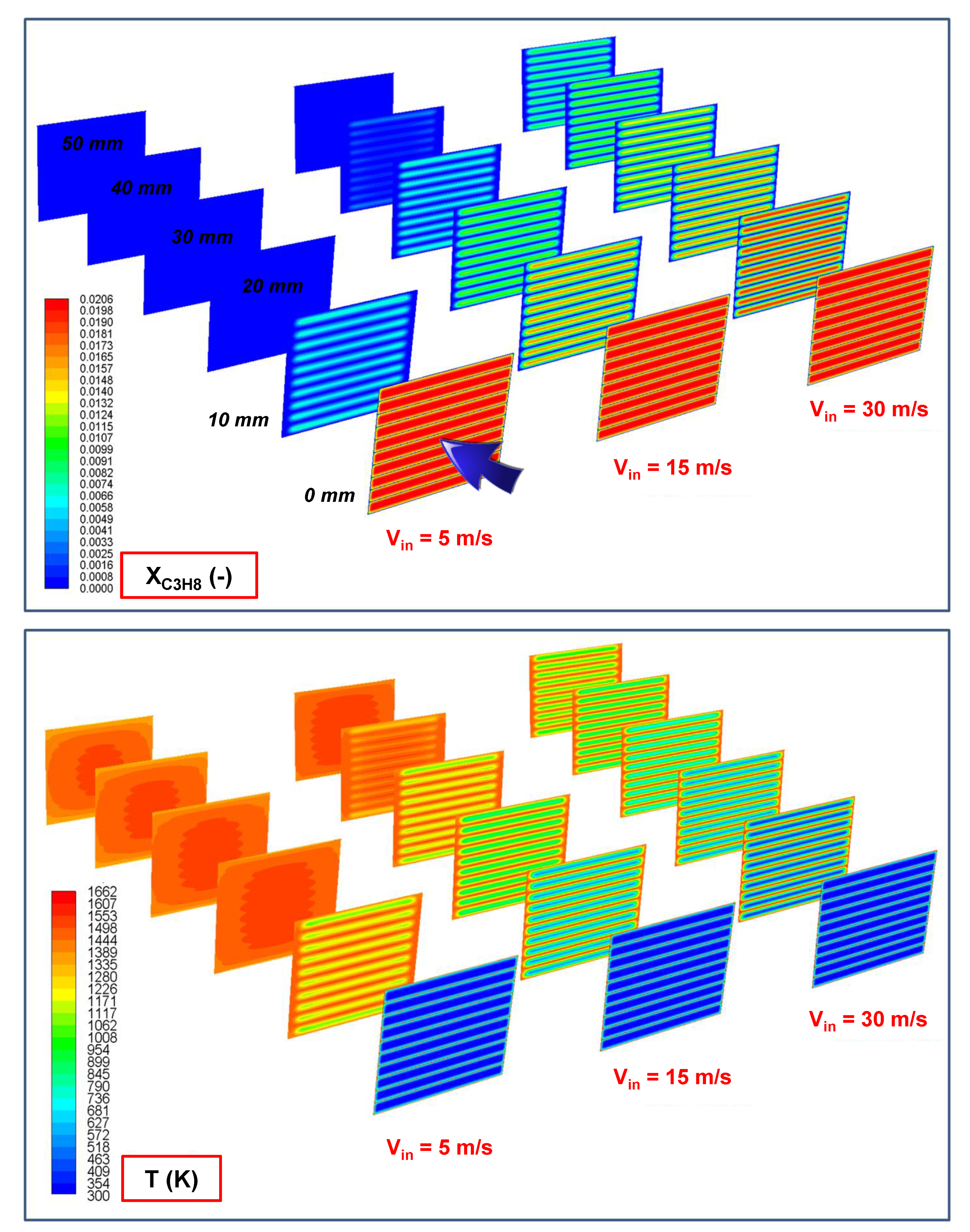
Figure 2.
Maps of (top) propane molar fraction, XC3H8, and (bottom) temperature, T, as calculated over different cross-sections of the micro-reactor (i.e., at 0 mm—inlet section; 10, 20, 30, 40, and 50 mm—exit section) at different values of inlet gas velocity (i.e., residence time). Nature-inspired (NI) configuration: hext = 20 W/m2 K.

Figure 3.
Maximum wall temperature, Twall_max, bulk temperature (at the exit section), Tbulk, and propane conversion, xC3H8, as a function of the residence time, τ. PC configuration: hext = 20 W/m2 K.
Figure 3.
Maximum wall temperature, Twall_max, bulk temperature (at the exit section), Tbulk, and propane conversion, xC3H8, as a function of the residence time, τ. PC configuration: hext = 20 W/m2 K.
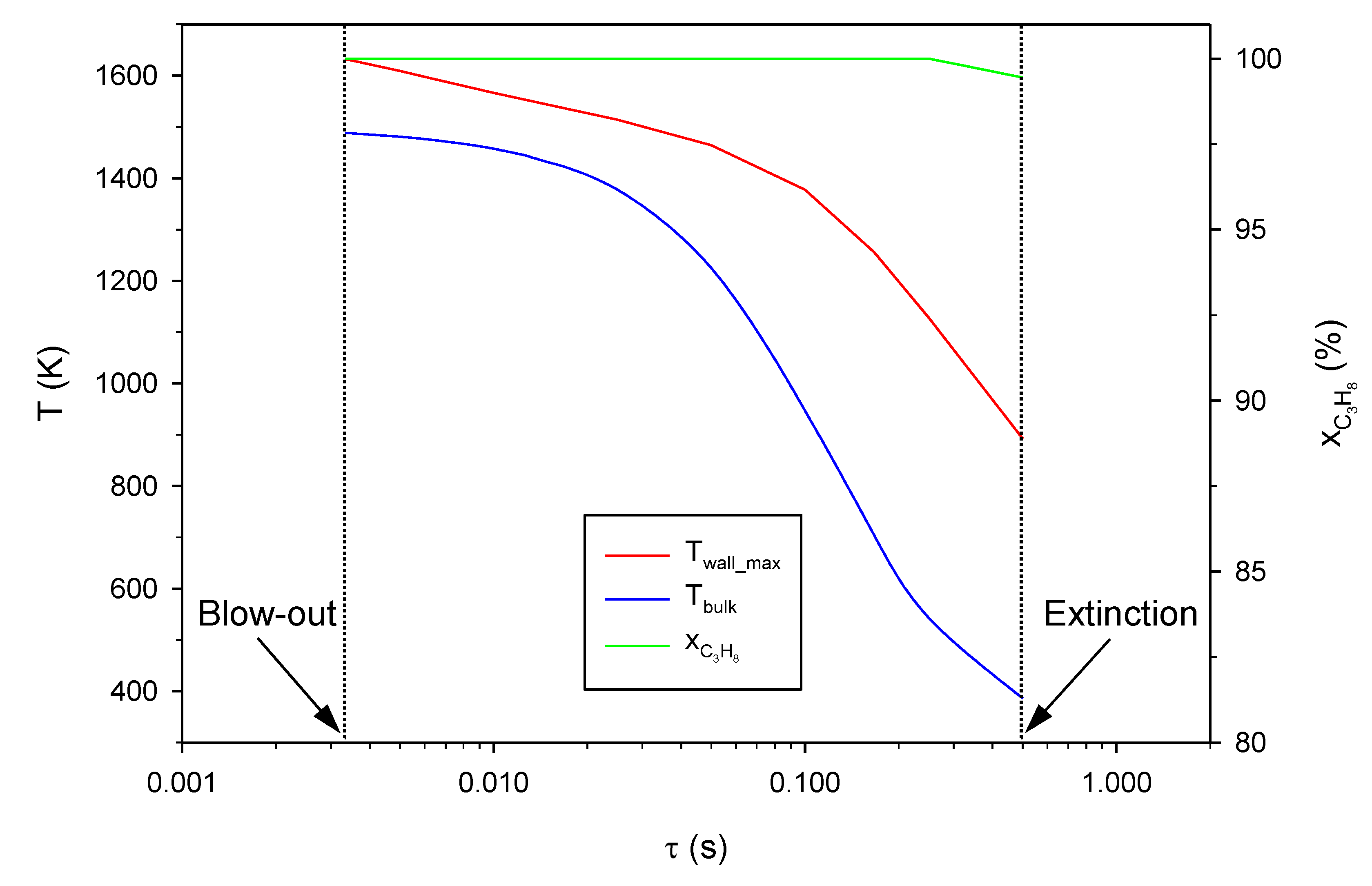
Figure 4.
Maximum wall temperature, Twall_max, bulk temperature (at the exit section), Tbulk, and propane conversion, xC3H8, as a function of the residence time, τ. NI configuration: hext = 20 W/m2 K.
Figure 4.
Maximum wall temperature, Twall_max, bulk temperature (at the exit section), Tbulk, and propane conversion, xC3H8, as a function of the residence time, τ. NI configuration: hext = 20 W/m2 K.
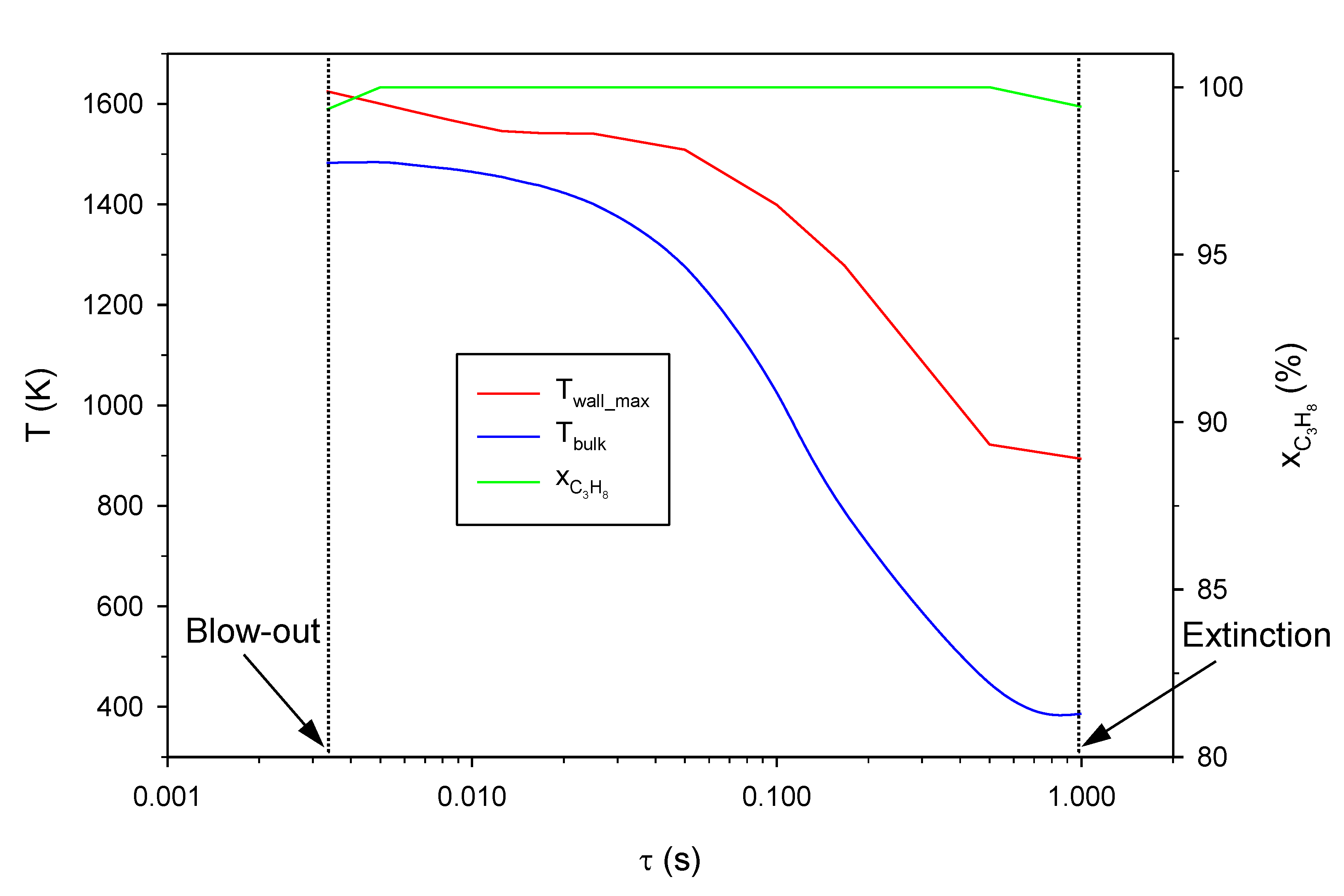
Figure 5.
Maximum wall temperature, Twall_max, as a function of R: comparison between PC and NI configurations (vin = 0.5 m/s).
Figure 5.
Maximum wall temperature, Twall_max, as a function of R: comparison between PC and NI configurations (vin = 0.5 m/s).

Figure 6.
Bulk temperature (at the exit section), Tbulk, as a function of R: comparison between PC and NI configurations (vin = 0.5 m/s).
Figure 6.
Bulk temperature (at the exit section), Tbulk, as a function of R: comparison between PC and NI configurations (vin = 0.5 m/s).
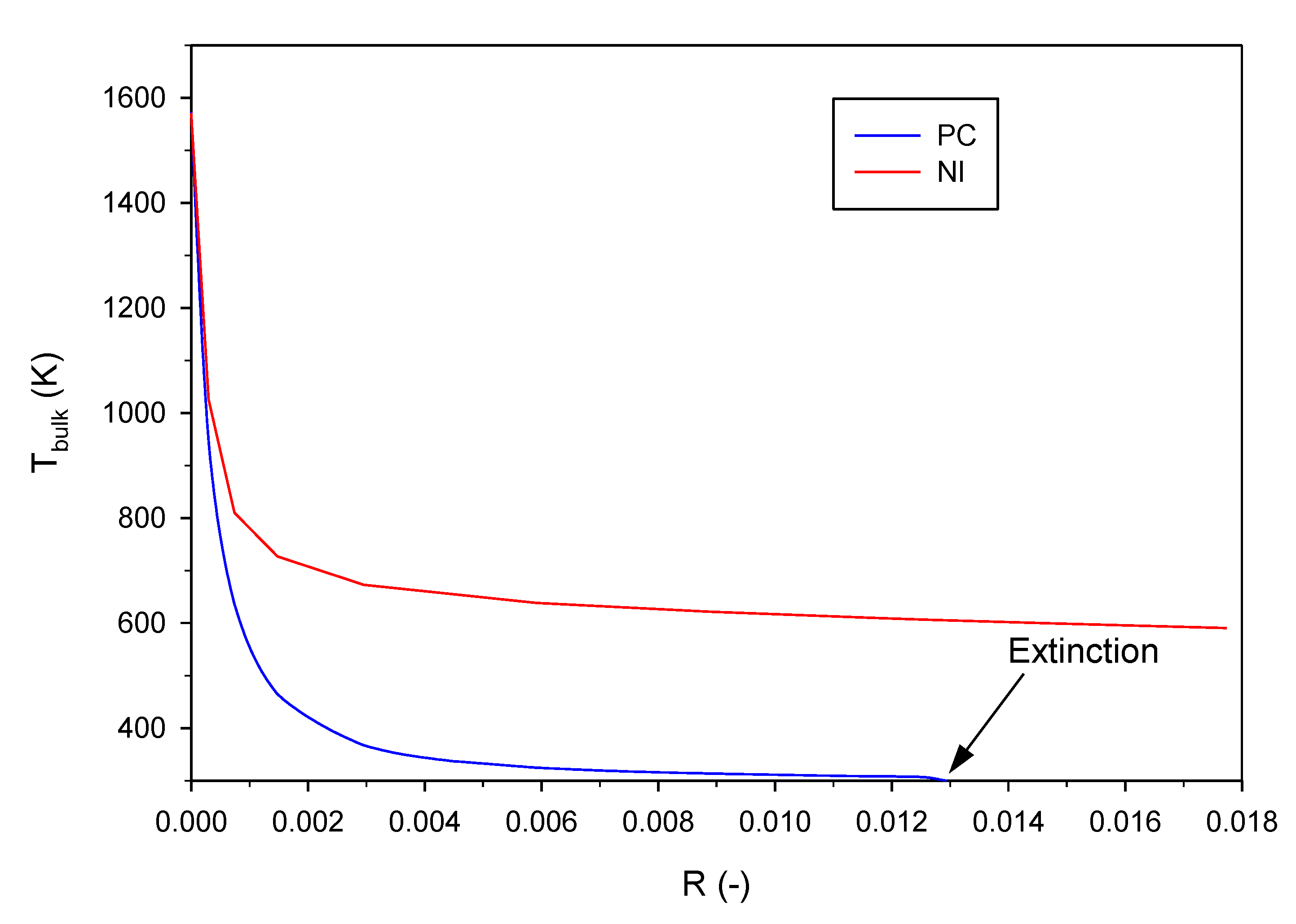
Figure 7.
Propane conversion, xC3H8, as a function of R: comparison between PC and NI configurations (vin = 0.5 m/s).
Figure 7.
Propane conversion, xC3H8, as a function of R: comparison between PC and NI configurations (vin = 0.5 m/s).
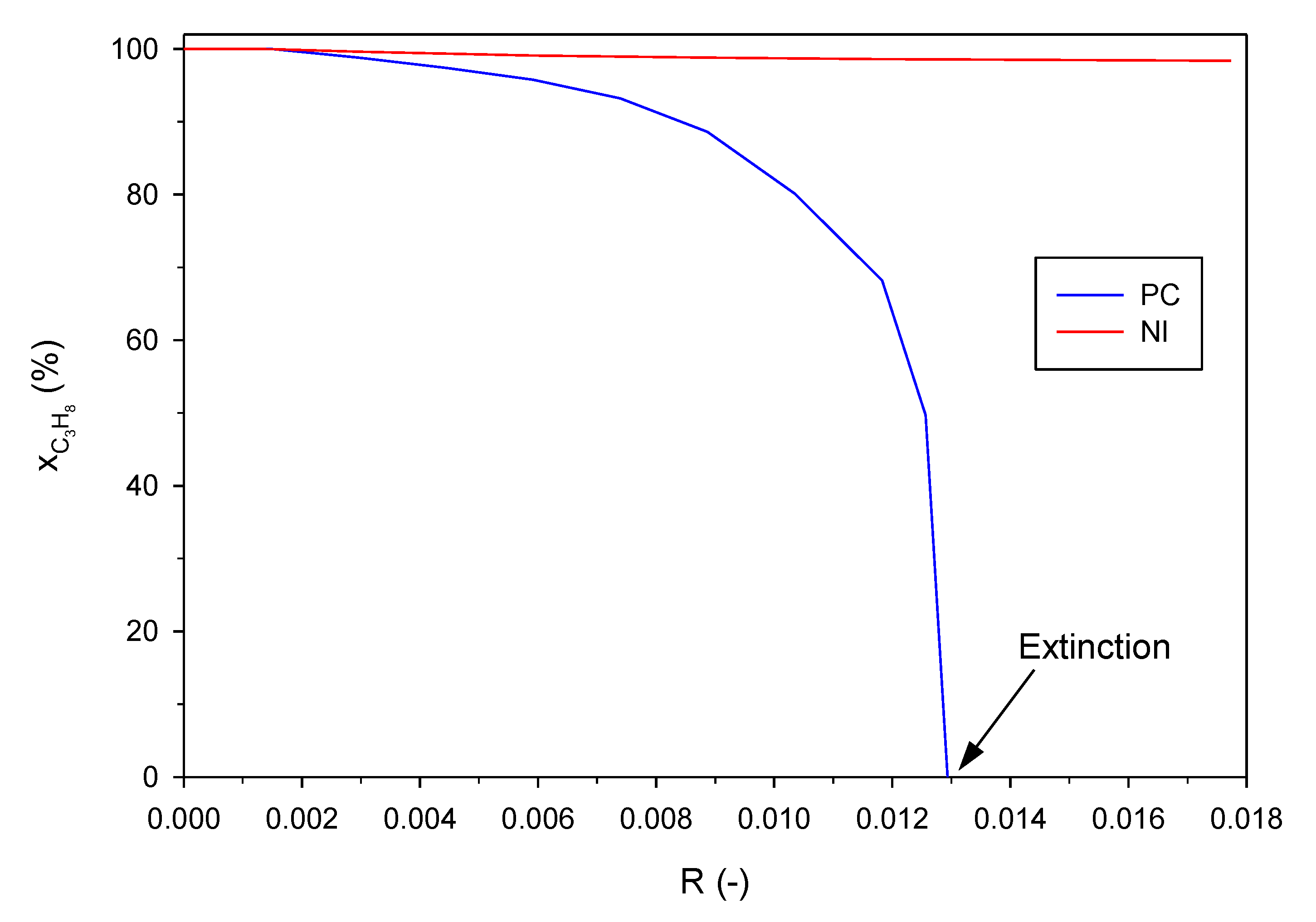
Figure 8.
Temperature maps computed for both PC and NI configurations at two different values of R (vin = 0.5 m/s).
Figure 8.
Temperature maps computed for both PC and NI configurations at two different values of R (vin = 0.5 m/s).
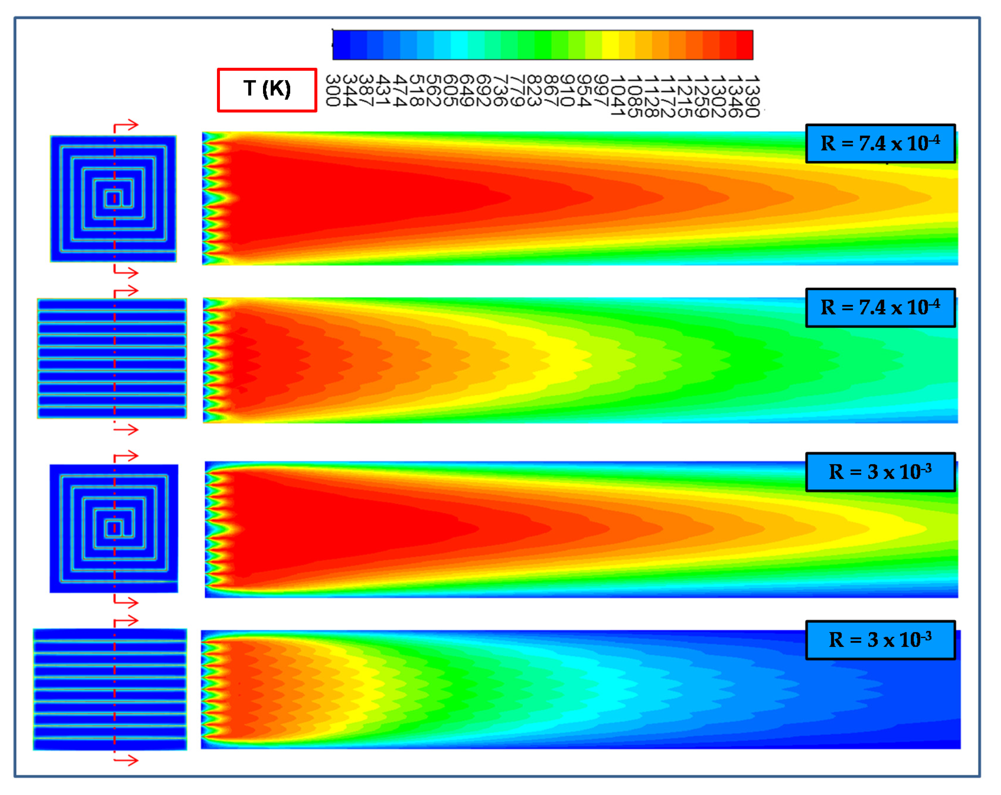
Figure 9.
Computational domains of (top) parallel-channel (PC) configuration and (bottom) nature-inspired (NI) configuration; the magnified image with red edges shows some geometrical details; an image of the cross-section of a reindeer nose (at around 10 cm into the nose) is also shown (from Magnanelli et al. [22]).
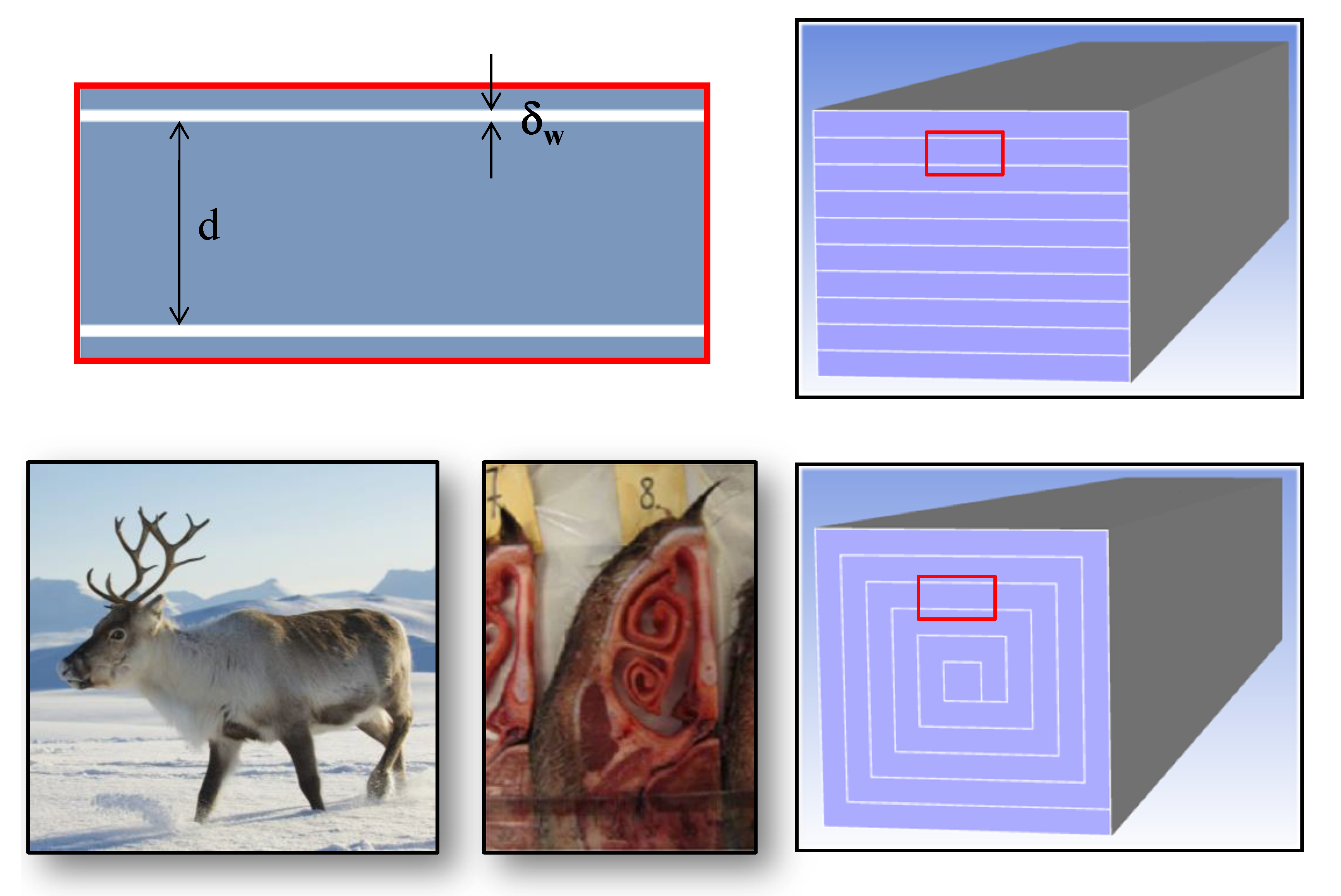
Figure 10.
Computational grids for parallel-channel (PC) configuration and nature-inspired (NI) configuration.
Figure 10.
Computational grids for parallel-channel (PC) configuration and nature-inspired (NI) configuration.


Table 1.
Values of the most important geometrical parameters for parallel-channel (PC) configuration and nature-inspired (NI) configuration.
Table 1.
Values of the most important geometrical parameters for parallel-channel (PC) configuration and nature-inspired (NI) configuration.
| Parameter | Value |
|---|---|
| Distance between catalytic walls, d (mm) | 0.783 |
| Thickness of the catalytic walls, δw (mm) | 0.045 |
| Length of the micro-reactor, L (mm) | 50 |
| Total catalytic surface area of the micro-reactor, Acat (mm2) | 11053 |
| Total catalytic surface area/volume of the micro-reactor, PC/NI, Acat/V (mm−1) | 2.56/2.42 |
| External surface area of the micro-reactor, PC/NI, Aext (mm2) | 1868/1911 |
Table 2.
Further simulation conditions.
| Parameter | Value |
|---|---|
| Inlet gas temperature, Tin (K) | 300 |
| Inlet fuel equivalence ratio (-) | 0.5 |
| Solid thermal conductivity, kw (W/m K) | 18 1 |
1 Walls were assumed as made of silicon carbide (SiC).
© 2020 by the authors. Licensee MDPI, Basel, Switzerland. This article is an open access article distributed under the terms and conditions of the Creative Commons Attribution (CC BY) license (http://creativecommons.org/licenses/by/4.0/).
Share and Cite
MDPI and ACS Style
Di Sarli, V.; Trofa, M.; Di Benedetto, A. A Novel Catalytic Micro-Combustor Inspired by the Nasal Geometry of Reindeer: CFD Modeling and Simulation. Catalysts 2020, 10, 606. https://doi.org/10.3390/catal10060606
AMA Style
Di Sarli V, Trofa M, Di Benedetto A. A Novel Catalytic Micro-Combustor Inspired by the Nasal Geometry of Reindeer: CFD Modeling and Simulation. Catalysts. 2020; 10(6):606. https://doi.org/10.3390/catal10060606
Chicago/Turabian StyleDi Sarli, Valeria, Marco Trofa, and Almerinda Di Benedetto. 2020. "A Novel Catalytic Micro-Combustor Inspired by the Nasal Geometry of Reindeer: CFD Modeling and Simulation" Catalysts 10, no. 6: 606. https://doi.org/10.3390/catal10060606
Note that from the first issue of 2016, this journal uses article numbers instead of page numbers. See further details here.