Designing Domain-Specific Heterogeneous Architectures from Dataflow Programs


Abstract
:1. Introduction
- A generic method to design domain-specific heterogeneous manycore architectures with an emphasis on custom-designed tiles was proposed.
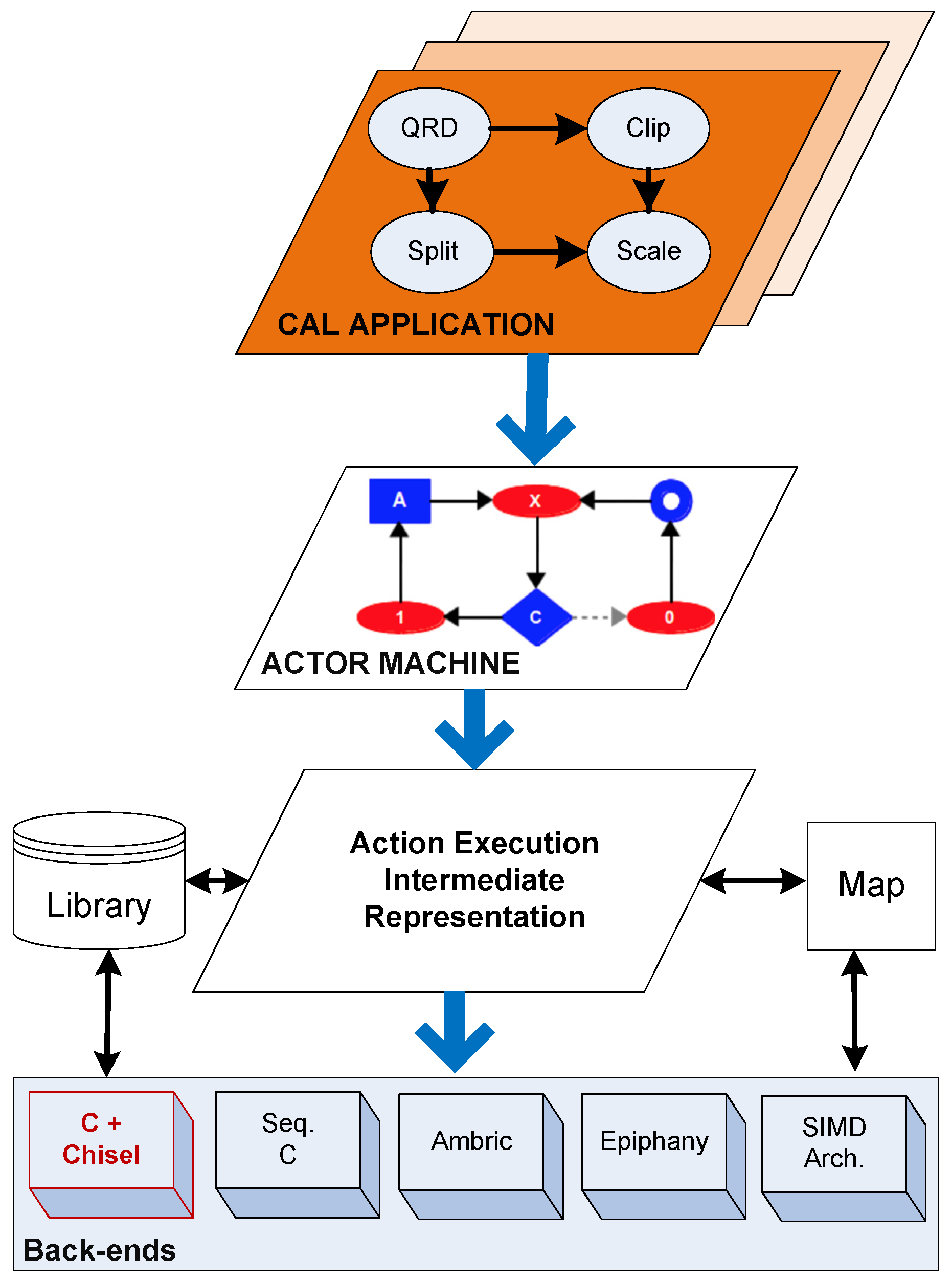
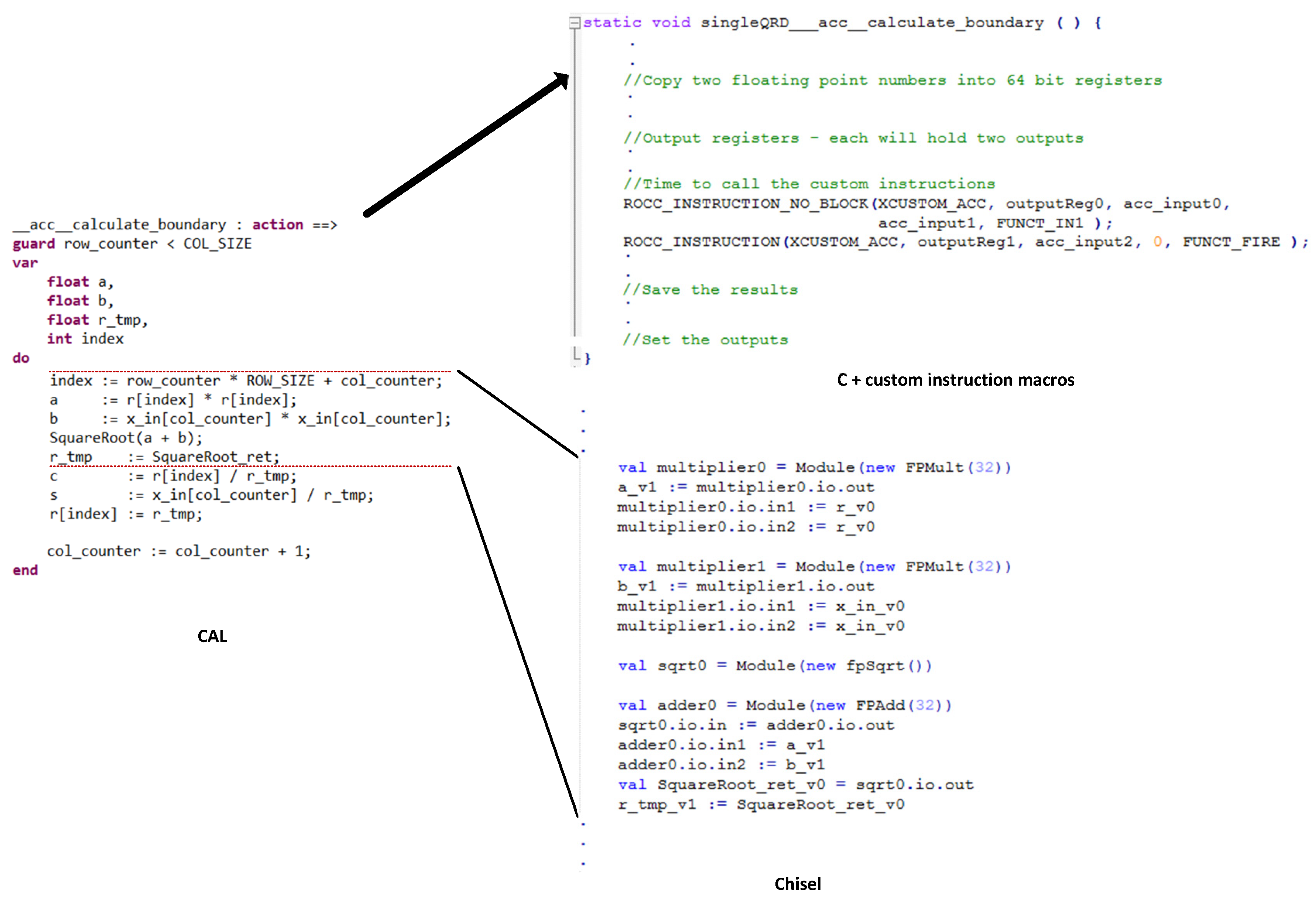
- An approach to design augmented cores (tiles) via instruction extension and hardware acceleration was realized, including development of a code generation tool to automate hardware accelerator generation directly from a dataflow application. This tool performs hardware/software codesign and generates C and Chisel code from CAL applications.
- The design method was evaluated using two case studies from baseband processing and radar signal processing. For these case studies, hand-written and automatically generated accelerators are used. The accelerators are integrated into a RISC-V core.
2. Related Works
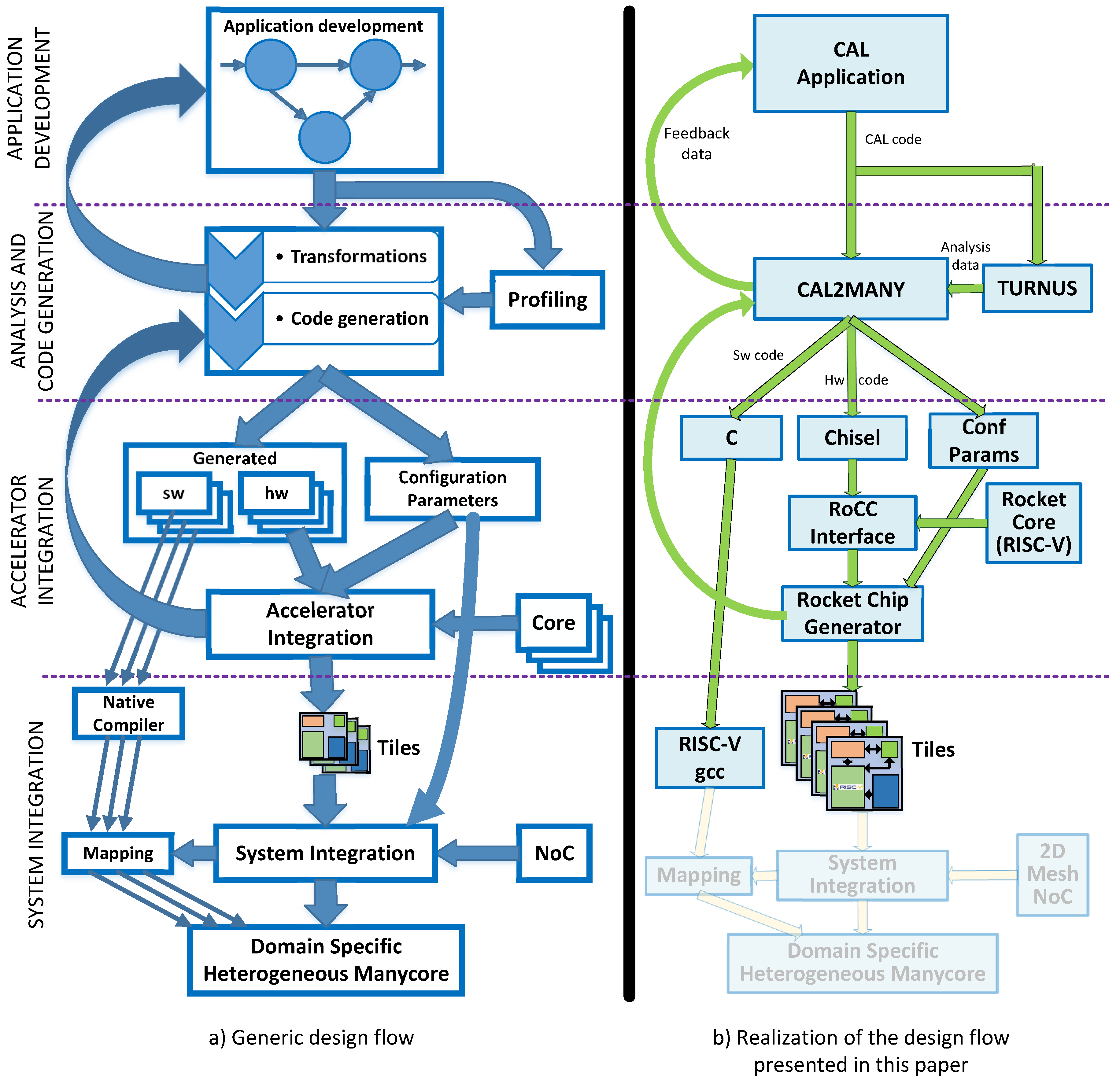
3. Design Approach
- Application development
- Analysis and code generation
- Accelerator integration
- System integration
3.1. Generic Design Flow
3.1.1. Application Development
3.1.2. Analysis
3.1.3. Code Generation
3.1.4. Accelerator Integration
3.1.5. System Integration
3.2. Realization of the Design Flow
3.2.1. Application Development
3.2.2. Analysis
3.2.3. Code Generation
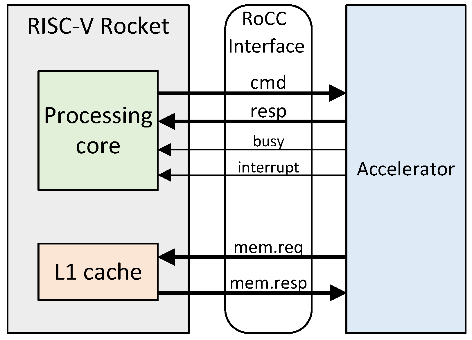
3.2.4. Accelerator Integration
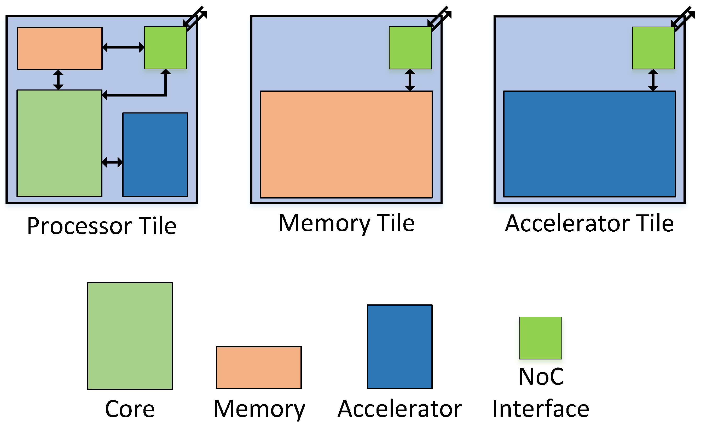
- Processor Tile, consisting of a processing core, local memory and optionally an accelerator
- Memory Tile, consisting of only memory
- Accelerator Tile, consisting of only an accelerator
3.2.5. System Integration
4. Case Studies and Implementations
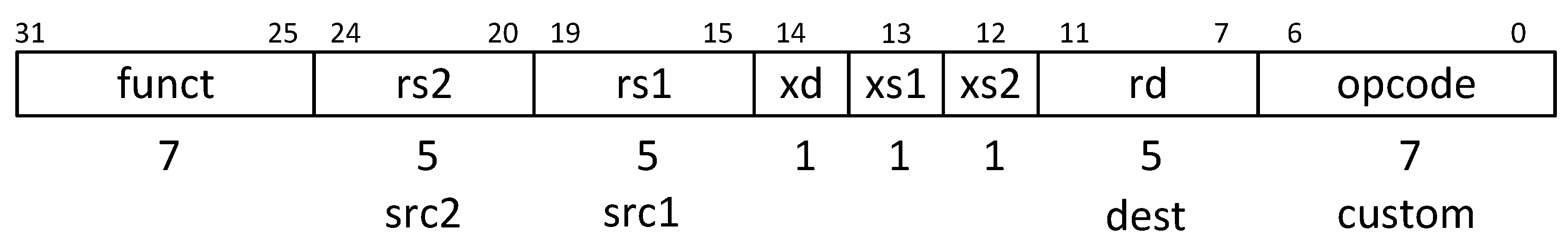
- Connect the RoCC interface to the I/O of the accelerator.
- Adjust the core configuration and binding the accelerator to a custom instruction.
- Adjust the platform configuration to use the new core configuration which includes the accelerator.
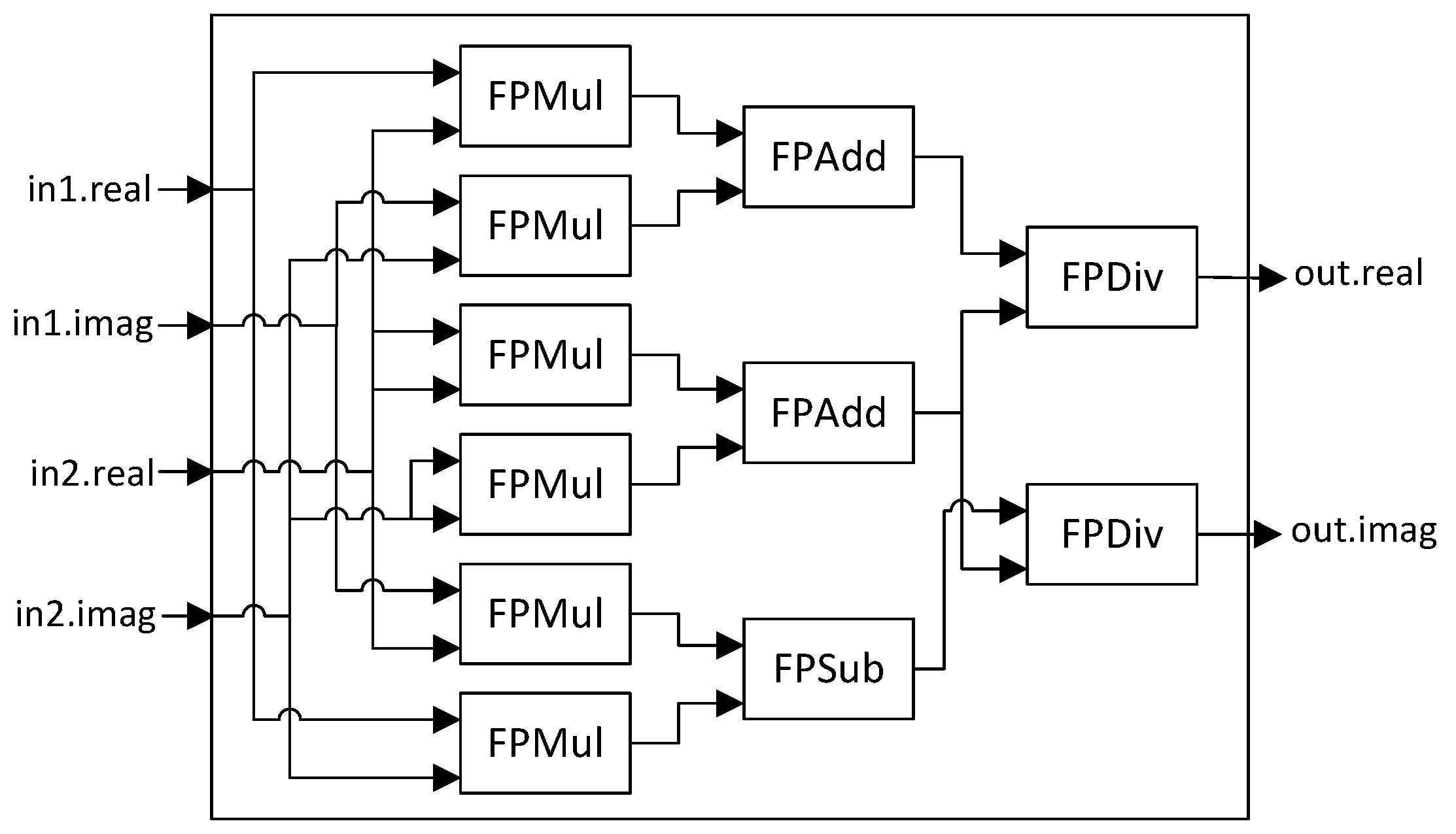
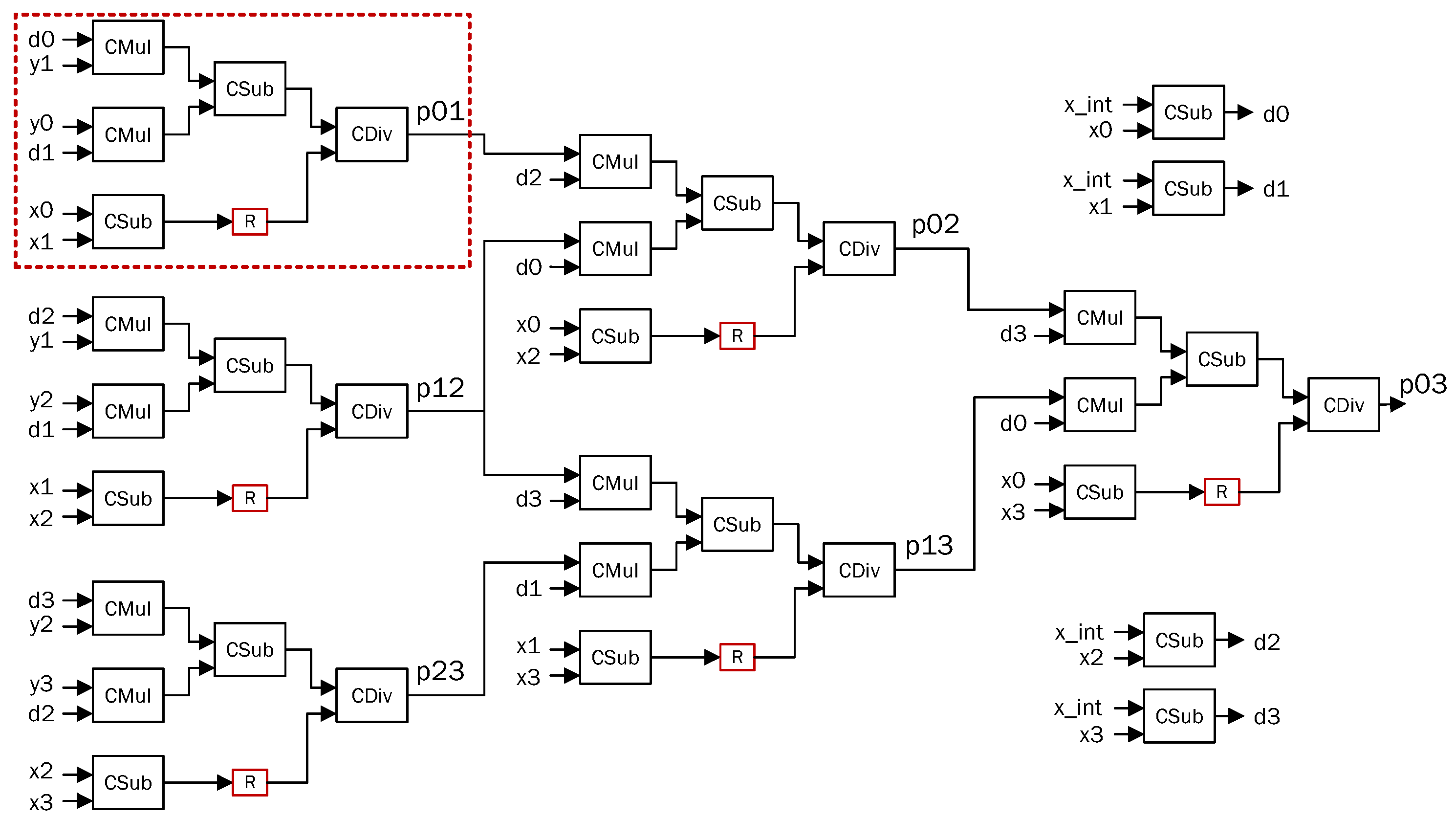
4.1. QR Decomposition
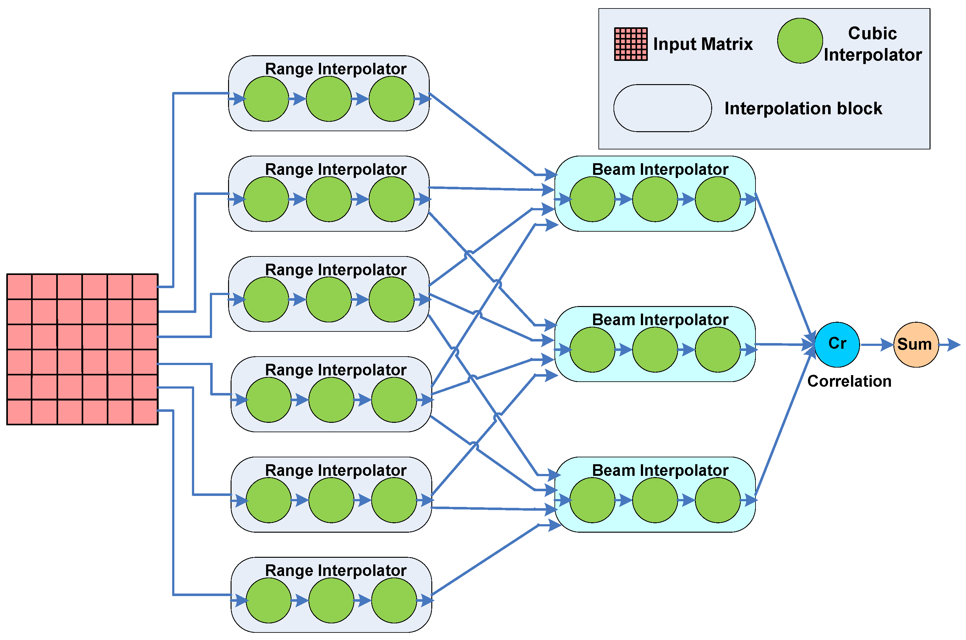
4.2. Autofocus Criterion Calculation in Synthetic Aperture Radar Systems
5. Results
5.1. QR Decomposition
5.2. Autofocus Criterion Calculation
6. Conclusions
Acknowledgments
Author Contributions
Conflicts of Interest
References
- Bohnenstiehl, B.; Stillmaker, A.; Pimentel, J.J.; Andreas, T.; Liu, B.; Tran, A.T.; Adeagbo, E.; Baas, B.M. KiloCore: A 32-nm 1000-processor computational array. IEEE J. Solid-State Circuits 2017, 52, 891–902. [Google Scholar] [CrossRef]
- Behling, S.; Bell, R.; Farrell, P.; Holthoff, H.; O’Connell, F.; Weir, W. The POWER4 Processor Introduction and Tuning Guide; IBM Redbooks: New York, NY, USA, 2001. [Google Scholar]
- Intel Corporation, Intel Pentium Processors. Available online: https://www.intel.com/content/www/us/en/products/processors/pentium.html (accessed on 20 December 2017).
- Rusek, F.; Persson, D.; Lau, B.K.; Larsson, E.G.; Marzetta, T.L.; Edfors, O.; Tufvesson, F. Scaling up MIMO: Opportunities and challenges with very large arrays. Signal Process. Mag. IEEE 2013, 30, 40–60. [Google Scholar] [CrossRef]
- Larsson, E.; Edfors, O.; Tufvesson, F.; Marzetta, T. Massive MIMO for next generation wireless systems. Commun. Mag. IEEE 2014, 52, 186–195. [Google Scholar] [CrossRef]
- Barham, P.; Dragovic, B.; Fraser, K.; Hand, S.; Harris, T.; Ho, A.; Neugebauer, R.; Pratt, I.; Warfield, A. Xen and the art of virtualization. In Proceedings of the ACM SIGOPS Operating Systems Review, Bolton Landing, NY, USA, 19–22 October 2003; Volume 37, pp. 164–177. [Google Scholar]
- Dua, R.; Raja, A.R.; Kakadia, D. Virtualization vs containerization to support paas. In Proceedings of the International Conference on Cloud Engineering (IC2E), Boston, MA, USA, 10–14 March 2014; pp. 610–614. [Google Scholar]
- Koufaty, D.; Marr, D.T. Hyperthreading technology in the netburst microarchitecture. IEEE Micro 2003, 23, 56–65. [Google Scholar] [CrossRef]
- Kumar, R.; Farkas, K.I.; Jouppi, N.P.; Ranganathan, P.; Tullsen, D.M. Single-ISA heterogeneous multi-core architectures: The potential for processor power reduction. In Proceedings of the 36th Annual IEEE/ACM International Symposium on Microarchitecture, MICRO-36, San Diego, CA, USA, 3–5 December 2003; pp. 81–92. [Google Scholar]
- Brodtkorb, A.R.; Dyken, C.; Hagen, T.R.; Hjelmervik, J.M.; Storaasli, O.O. State-of-the-art in heterogeneous computing. Sci. Progr. 2010, 18, 1–33. [Google Scholar] [CrossRef]
- Liu, S.; Ro, W.W.; Liu, C.; Salas, A.C.; Cérin, C.; Han, J.J.; Gaudiot, J.L. EHA: The extremely heterogeneous architecture. In Proceedings of the 12th International Symposium on Pervasive Systems, Algorithms and Networks (ISPAN), San Marcos, TX, USA, 13–15 December 2012; pp. 30–36. [Google Scholar]
- Mittal, S. A survey of techniques for architecting and managing asymmetric multicore processors. ACM Comput. Surv. (CSUR) 2016, 48, 45. [Google Scholar] [CrossRef]
- Zarrin, J.; Aguiar, R.L.; Barraca, J.P. Manycore simulation for peta-scale system design: Motivation, tools, challenges and prospects. Simul. Model. Pract. Theory 2017, 72, 168–201. [Google Scholar] [CrossRef]
- Binkert, N.; Beckmann, B.; Black, G.; Reinhardt, S.K.; Saidi, A.; Basu, A.; Hestness, J.; Hower, D.R.; Krishna, T.; Sardashti, S.; et al. The gem5 simulator. ACM Sigarch Comput. Archit. News 2011, 39, 1–7. [Google Scholar] [CrossRef]
- Sanchez, D.; Kozyrakis, C. ZSim: Fast and accurate microarchitectural simulation of thousand-core systems. ACM Sigarch Comput. Archit. News 2013, 41, 475–486. [Google Scholar] [CrossRef]
- Miller, J.E.; Kasture, H.; Kurian, G.; Gruenwald, C.; Beckmann, N.; Celio, C.; Eastep, J.; Agarwal, A. Graphite: A distributed parallel simulator for multicores. In Proceedings of the 16th International Symposium on High Performance Computer Architecture (HPCA), Bangalore, India, 9–14 January 2010; pp. 1–12. [Google Scholar]
- Carlson, T.E.; Heirmant, W.; Eeckhout, L. Sniper: Exploring the level of abstraction for scalable and accurate parallel multi-core simulation. In Proceedings of the International Conference on High Performance Computing, Networking, Storage and Analysis (SC), Seatle, WA, USA, 12–18 November 2011; pp. 1–12. [Google Scholar]
- Fu, Y.; Wentzlaff, D. PriME: A parallel and distributed simulator for thousand-core chips. In Proceedings of the IEEE International Symposium on Performance Analysis of Systems and Software (ISPASS), Monterey, CA, USA, 23–25 March 2014; pp. 116–125. [Google Scholar]
- Hardavellas, N.; Somogyi, S.; Wenisch, T.F.; Wunderlich, R.E.; Chen, S.; Kim, J.; Falsafi, B.; Hoe, J.C.; Nowatzyk, A.G. Simflex: A fast, accurate, flexible full-system simulation framework for performance evaluation of server architecture. ACM Sigmetr. Perform. Eval. Rev. 2004, 31, 31–34. [Google Scholar] [CrossRef]
- Gebrewahid, E.; Yang, M.; Cedersjo, G.; Ul-Abdin, Z.; Gaspes, V.; Janneck, J.W.; Svensson, B. Realizing efficient execution of dataflow actors on manycores. In Proceedings of the 12th IEEE International Conference on Embedded and Ubiquitous Computing (EUC), Milano, Italy, 26–28 August 2014; pp. 321–328. [Google Scholar]
- Bachrach, J.; Vo, H.; Richards, B.; Lee, Y.; Waterman, A.; Avižienis, R.; Wawrzynek, J.; Asanović, K. Chisel: Constructing hardware in a scala embedded language. In Proceedings of the 49th Annual Design Automation Conference, San Francisco, CA, USA, 3–7 June 2012; pp. 1216–1225. [Google Scholar]
- Savas, S.; Raase, S.; Gebrewahid, E.; Ul-Abdin, Z.; Nordström, T. Dataflow implementation of qr decomposition on a manycore. In Proceedings of the Fourth ACM International Workshop on Many-core Embedded Systems, Seoul, South Korea, 18–22 June 2016; pp. 26–30. [Google Scholar]
- Paulraj, A.J.; Gore, D.A.; Nabar, R.U.; Bolcskei, H. An overview of MIMO communications-a key to gigabit wireless. Proc. IEEE 2004, 92, 198–218. [Google Scholar] [CrossRef]
- Ul-Abdin, Z.; Ahlander, A.; Svensson, B. Energy-Efficient Synthetic-Aperture Radar Processing on a Manycore Architecture. In Proceedings of the 2013 42nd International Conference on Parallel Processing, Lyon, France, 1–4 October 2013; pp. 330–338. [Google Scholar]
- Neville, E.H. Iterative Interpolation; St. Joseph’s IS Press: Trivandrum, India, 1934. [Google Scholar]
- Eker, J.; Janneck, J.W. Dataflow programming in CAL—balancing expressiveness, analyzability, and implementability. In Proceedings of the Conference Record of the Forty Sixth Asilomar Conference on Signals, Systems and Computers (ASILOMAR), Pacific Grove, CA, USA, 4–7 November 2012; pp. 1120–1124. [Google Scholar]
- Rocket Core Overview. Available online: http://www.lowrisc.org/docs/tagged-memory-v0.1/rocket-core/ (accessed on 4 April 2018).
- Waterman, A.; Lee, Y.; Patterson, D.A.; Asanovic, K. The risc-v instruction set manual, volume I: Base user-level isa. EECS Dep. 2011, 7, 475. [Google Scholar]
- Asanovic, K.; Avizienis, R.; Bachrach, J.; Beamer, S.; Biancolin, D.; Celio, C.; Cook, H.; Dabbelt, D.; Hauser, J.; Izraelevitz, A.; et al. The Rocket Chip Generator; EECS Department, University of California: Berkeley, CA, USA, 2016. [Google Scholar]
- Sano, K.; Hatsuda, Y.; Yamamoto, S. Scalable streaming-array of simple soft-processors for stencil computations with constant memory-bandwidth. In Proceedings of the 19th Annual International Symposium on Field-Programmable Custom Computing Machines (FCCM), Salt Lake City, UT, USA, 1–3 May 2011; pp. 234–241. [Google Scholar]
- Tanabe, S.; Nagashima, T.; Yamaguchi, Y. A study of an FPGA based flexible SIMD processor. ACM Sigarch Comput. Archit. News 2011, 39, 86–89. [Google Scholar] [CrossRef]
- Schurz, F.; Fey, D. A programmable parallel processor architecture in FPGAs for image processing sensors. In Proceedings of the integrated design and process technology (IDPT’07) Conference, Antalya, Turkey, 3–8 June 2007; pp. 30–35. [Google Scholar]
- Ajayi, T.; Al-Hawaj, K.; Amarnath, A.; Dai, S.; Davidson, S.; Gao, P.; Liu, G.; Lotfi, A.; Puscar, J.; Rao, A.; et al. Celerity: An Open-Source RISC-V Tiered Accelerator Fabric. In Proceedings of the Symposium on High Performance Chips (Hot Chips), Cupertino, CA, USA, 20–22 August 2017. [Google Scholar]
- Svensson, B. A study of design efficiency with a high-level language for FPGAs. In Proceedings of the International Conference on Parallel and Distributed Processing Symposium (IPDPS), Long Beach, California, USA, 26–30 March 2007; pp. 1–7. [Google Scholar]
- Bjesse, P.; Claessen, K.; Sheeran, M.; Singh, S. Lava: Hardware design in Haskell. In Proceedings of the Third ACM SIGPLAN International Conference on Functional Programming, Baltimore, MD, USA, 26–29 September 1998; Volume 34, pp. 174–184. [Google Scholar]
- Baaij, C.; Kooijman, M.; Kuper, J.; Boeijink, A.; Gerards, M. Clash: Structural descriptions of synchronous hardware using haskell. In Proceedings of the 13th Euromicro Conference on Digital System Design: Architectures, Methods and Tools (DSD), Lille, France, 1–3 September 2010; pp. 714–721. [Google Scholar]
- CLASH, from Haskell to Hardware. Available online: http://www.clash-lang.org/ (accessed on 21 April 2018).
- Vivado Design Suite, Xilinx Inc. Available online: https://www.xilinx.com/products/design-tools/vivado.html/ (accessed on 21 April 2018).
- Catapult C Synthesis, Calypto Design Systems. Available online: http://calypto.agranderdesign.com/catapult_c_synthesis.php/ (accessed on 21 April 2018).
- Impulse CoDeveloper, Impulse Accelerated Technologies. Available online: http://www.impulseaccelerated.com/products.htm (accessed on 21 April 2018).
- EXCite, Y Explorations Inc. Available online: http://www.yxi.com/products.php (accessed on 21 April 2018).
- Stratus High-Level Synthesis, Cadence Design Systems. Available online: https://www.cadence.com/content/cadence-www/global/en_US/home/tools/digital-design-and-signoff/synthesis/stratus-high-level-synthesis.html/ (accessed on 21 April 2018).
- Synphony C Compiler, Synopsis Inc. Available online: https://www.synopsys.com/implementation-and-signoff/rtl-synthesis-test/synphony-c-compiler.html (accessed on 21 April 2018).
- Catapult High-Level Synthesis Platform, Mentor Graphics. Available online: https://www.mentor.com/hls-lp/catapult-high-level-synthesis/ (accessed on 21 April 2018).
- CyberWorkBench, NEC Corporation. Available online: http://www.nec.com/en/global/prod/cwb/index.html? (accessed on 21 April 2017).
- Trajkovic, J.; Abdi, S.; Nicolescu, G.; Gajski, D.D. Automated generation of custom processor core from c code. J. Elect. Comput. Eng. 2012, 2012, 7. [Google Scholar] [CrossRef]
- Goodwin, D.; Petkov, D. Automatic generation of application specific processors. In Proceedings of the 2003 International Conference on Compilers, Architecture and Synthesis for Embedded Systems, San Jose, CA, USA, October 30–November 1 2003; pp. 137–147. [Google Scholar]
- Clark, N.T.; Zhong, H.; Mahlke, S.A. Automated custom instruction generation for domain-specific processor acceleration. IEEE Trans. Comput. 2005, 54, 1258–1270. [Google Scholar] [CrossRef]
- Koeplinger, D.; Delimitrou, C.; Prabhakar, R.; Kozyrakis, C.; Zhang, Y.; Olukotun, K. Automatic generation of efficient accelerators for reconfigurable hardware. In Proceedings of the 43rd International Symposium on Computer Architecture, Seoul, South Korea, 18–22 June 2016; pp. 115–127. [Google Scholar]
- Kathail, V.; Hwang, J.; Sun, W.; Chobe, Y.; Shui, T.; Carrillo, J. SDSoC: A Higher-level Programming Environment for Zynq SoC and Ultrascale+ MPSoC. In Proceedings of the 2016 ACM/SIGDA International Symposium on Field-Programmable Gate Arrays, Monterey, CA, USA, 21–23 February 2016; p. 4. [Google Scholar]
- Janneck, J.W.; Miller, I.D.; Parlour, D.B.; Roquier, G.; Wipliez, M.; Raulet, M. Synthesizing hardware from dataflow programs. J. Signal Process. Syst. 2011, 63, 241–249. [Google Scholar] [CrossRef] [Green Version]
- Siret, N.; Wipliez, M.; Nezan, J.F.; Rhatay, A. Hardware code generation from dataflow programs. In Proceedings of the Conference on Design and Architectures for Signal and Image Processing (DASIP), Edinburgh, UK, 26–28 October 2010; pp. 113–120. [Google Scholar]
- Bezati, E.; Mattavelli, M.; Janneck, J.W. High-level synthesis of dataflow programs for signal processing systems. In Proceedings of the 8th International Symposium on Image and Signal Processing and Analysis (ISPA), Trieste, Italy, 4–6 September 2013; pp. 750–754. [Google Scholar]
- Zarrin, J.; Aguiar, R.L.; Barraca, J.P. Hard: Hybrid adaptive resource discovery for jungle computing. J. Netw. Comput. Appl. 2017, 90, 42–73. [Google Scholar] [CrossRef]
- Michalska, M.; Boutellier, J.; Mattavelli, M. A methodology for profiling and partitioning stream programs on many-core architectures. Procedia Comput. Sci. 2015, 51, 2962–2966. [Google Scholar] [CrossRef]
- Wang, C.; Li, X.; Zhang, H.; Wang, A.; Zhou, X. Hot spots profiling and dataflow analysis in custom dataflow computing SoftProcessors. J. Syst. Softw. 2017, 125, 427–438. [Google Scholar] [CrossRef]
- Janneck, J.W.; Miller, I.D.; Parlour, D.B. Profiling dataflow programs. In Proceedings of the International Conference on Multimedia and Expo, Hannover, Germany, 23–26 April 2008; pp. 1065–1068. [Google Scholar]
- Savas, S.; Gebrewahid, E.; Ul-Abdin, Z.; Nordström, T.; Yang, M. An evaluation of code generation of dataflow languages on manycore architectures. In Proceedings of the 20th International Conference on Embedded and Real-Time Computing Systems and Applications (RTCSA), Chongqing, China, 20–22 August 2014; pp. 1–9. [Google Scholar]
- Olofsson, A.; Nordström, T.; Ul-Abdin, Z. Kickstarting high-performance energy-efficient manycore architectures with epiphany. In Proceedings of the 48th Asilomar Conference on Signals, Systems and Computers, Pacific Grove, CA, USA, 2–5 November 2014; pp. 1719–1726. [Google Scholar]
- Salminen, E.; Kulmala, A.; Hamalainen, T.D. Survey of network-on-chip proposals. White Pap. OCP-IP 2008, 1, 13. [Google Scholar]
- Fernandez-Alonso, E.; Castells-Rufas, D.; Joven, J.; Carrabina, J. Survey of NoC and programming models proposals for MPSoC. Int. J. Comput. Sci. Issues 2012, 9, 22–32. [Google Scholar]
- Agarwal, A.; Iskander, C.; Shankar, R. Survey of network on chip (noc) architectures & contributions. J. Eng. Comput. Archit. 2009, 3, 21–27. [Google Scholar]
- Najjar, W.A.; Lee, E.A.; Gao, G.R. Advances in the dataflow computational model. Parallel Comput. 1999, 25, 1907–1929. [Google Scholar] [CrossRef]
- Horowitz, E. Data Flow Programming Languages. In Fundamentals of Programming Languages; Springer: Berlin/Heidelberg, Germany, 1984; pp. 373–393. [Google Scholar]
- Bhattacharyya, S.S.; Eker, J.; Janneck, J.W.; Lucarz, C.; Mattavelli, M.; Raulet, M. Overview of the MPEG Reconfigurable Video Coding Framework. J. Signal Process. Syst. 2011, 63, 251–263. [Google Scholar] [CrossRef] [Green Version]
- Savas, S. Implementation and Evaluation of Mpeg-4 Simple Profile Decoder on a Massively Parallel Processor Array. Master’s Thesis, Halmstad University, Halmstad, Sweden, 2011. [Google Scholar]
- Nethercote, N.; Seward, J. Valgrind: A framework for heavyweight dynamic binary instrumentation. In Proceedings of the 28th ACM SIGPLAN Conference on Programming Language Design and Implementation, San Diego, CA, USA, 11–13 June 2007; Volume 42, pp. 89–100. [Google Scholar]
- Fenlason, J.; Stallman, R. GNU Gprof. GNU Binutils. Available online: http://www.gnu.org/software/binutils (accessed on 21 April 2018).
- Casale-Brunet, S.; Alberti, C.; Mattavelli, M.; Janneck, J.W. Turnus: A unified dataflow design space exploration framework for heterogeneous parallel systems. In Proceedings of the Conference on Design and Architectures for Signal and Image Processing (DASIP), Cagliari, Italy, 8–10 October 2013; pp. 47–54. [Google Scholar]
- Yviquel, H.; Lorence, A.; Jerbi, K.; Cocherel, G.; Sanchez, A.; Raulet, M. Orcc: Multimedia Development Made Easy. In Proceedings of the 21st ACM International Conference on Multimedia, Barcelona, Spain, 21–25 October 2013; pp. 863–866. [Google Scholar]
- Pelcat, M.; Nezan, J.F.; Piat, J.; Croizer, J.; Aridhi, S. A system-level architecture model for rapid prototyping of heterogeneous multicore embedded systems. In Proceedings of the Conference on Design and Architectures for Signal and Image Processing (DASIP), Sophia Antipolis, France, 22–24 October 2009; p. 8. [Google Scholar]
- Atasu, K.; Dimond, R.G.; Mencer, O.; Luk, W.; Özturan, C.; Dündar, G. Optimizing instruction-set extensible processors under data bandwidth constraints. In Proceedings of the Conference on Design, Automation and Test in Europe, EDA Consortium, Nice, France, 16–20 April 2007; pp. 588–593. [Google Scholar]
- Haaß, M.; Bauer, L.; Henkel, J. Automatic custom instruction identification in memory streaming algorithms. In Proceedings of the 2014 International Conference on Compilers, Architecture and Synthesis for Embedded Systems, New Delhi, India, 12–17 October 2014; p. 6. [Google Scholar]
- Janneck, J. A machine model for dataflow actors and its applications. In Proceedings of the Conference Record of the 45th Asilomar Conference on Signals, Systems and Computers (ASILOMAR), Pacific Grove, CA, USA, 6–9 November 2011; pp. 756–760. [Google Scholar]
- Karlsson, A.; Sohl, J.; Liu, D. Epuma: A processor architecture for future dsp. In Proceedings of the International Conference on Digital Signal Processing (DSP), Singapore, 21–24 July 2015; pp. 253–257. [Google Scholar]
- Zhang, C. Dynamically Reconfigurable Architectures for Real-Time Baseband Processing. Ph.D. Dissertation, Lund University, Lund, Sweden, 2014. [Google Scholar]
- Savas, S.; Hertz, E.; Nordström, T.; Ul-Abdin, Z. Efficient Single-Precision Floating-Point Division Using Harmonized Parabolic Synthesis. In Proceedings of the Annual Symposium on VLSI (ISVLSI), Bochum, Germany, 3–5 July 2017; pp. 110–115. [Google Scholar]
- Odersky, M. The Scala Language Specification; Version 2.9; Programming Methods Laboratory, EPFL: Lausanne, Switzerland, 2014. [Google Scholar]
- Asanovic, K.; Patterson, D.A.; Celio, C. The Berkeley Out-of-Order Machine (BOOM): An Industry-Competitive, Synthesizable, Parameterized RISC-V Processor; Technical Report; University of California at Berkeley: Berkeley, CA, USA, 2015. [Google Scholar]
- Celio, C. RISC-V Sodor CPU. Available online: https://github.com/ucb-bar/riscv-sodor (accessed on 3 November 2017).
- Clifford, W. PicoRV32—A Size-Optimized RISC-V CPU. Available online: https://github.com/cliffordwolf/picorv32 (accessed on 3 November 2017).
- Syntacore. SCR1—An Open-Source RISC-V Compatible MCU Core. Available online: https://github.com/syntacore/scr1 (accessed on 3 November 2017).
- Yarp, C. An Introduction to the Rocket Custom Coprocessor Interface. Available online: http://c199.eecs.berkeley.edu/~cs250/sp16/disc/Disc02.pdf (accessed on 10 November 2017).
- Snyder, W.; Galbi, D.; Wasson, P. Verilator, Verilog HDL Simulator. Available online: https://www.veripool.org/wiki/verilator (accessed on 10 November 2017).
- Goodall, C.R. 13 Computation using the QR decomposition. Handb. Stat. 1993, 9, 467–508. [Google Scholar]
- Savas, S. Linear Algebra for Array Signal Processing on a Massively Parallel Dataflow Architecture. Bachelor’s Thesis, School of Information Technology, Halmstad University, Halmstad, Sweden, 2009. [Google Scholar]
- Gebrewahid, E. Tools to Compile Dataflow Programs for Manycores. Ph.D. Thesis, Halmstad University Press, Halmstad, Sweden, 2017. [Google Scholar]
- IEEE Task P754. IEEE 754-2008, Standard for Floating-Point Arithmetic; IEEE Press: Piscataway, NJ, USA, 2008; p. 58. [Google Scholar]


| Flat Accelerator | Folded Accelerator | |
|---|---|---|
| CMul | 12 | 2 |
| CDiv | 6 | 1 |
| CSub | 16 | 6 |
| Flat Accelerator | Folded Accelerator | CMul | CSub | CDiv | |
|---|---|---|---|---|---|
| FPMul | 84 | 14 | 4 | - | 6 |
| FPDiv | 12 | 2 | - | - | 2 |
| FPSub | 50 | 15 | 1 | 2 | 1 |
| FPAdd | 24 | 4 | 1 | - | 2 |
| Cycle Count | Clock Freq. | |
|---|---|---|
| Rocket Core | 366 k | 58 MHz |
| Rocket Core + Generated Accelerator | 92 k | 56 MHz |
| Rocket Core + Hand-written Accelerator | 89 k | 56 Mhz |
| LUT | FF | BRAM | DSP | Clock Freq. | |
|---|---|---|---|---|---|
| Rocket Core | 39,843 | 16,512 | 12 | 24 | 58 MHz |
| Generated Accelerator | 1165 | 914 | 2 | 25 | 104 MHz |
| Hand-written Accelerator | 999 | 812 | 2 | 25 | 104 MHz |
| Cycle Count | Clock Freq. | |
|---|---|---|
| Rocket Core | 306 k cycles | 58 MHz |
| Rocket Core + Hand-written Flat Accelerator | 64 k cycles | 56 MHz |
| Rocket Core + Hand-written Folded Accelerator | 108 k cycles | 58 MHz |
| Rocket Core + Generated Accelerator | 108 k cycles | 58 MHz |
| LUT | FF | DSP | BRAM | Clock Freq. | |
|---|---|---|---|---|---|
| Rocket Core | 39,843 | 16,512 | 24 | 12 | 58 MHz |
| Hand-written Flat Accelerator | 24,707 | 14,471 | 252 | 3 | 126 MHz |
| Rocket + Hand-written Flat Accelerator | 68,860 | 36,722 | 276 | 16 | 56 MHz |
| Hand-written Folded Accelerator | 5187 | 3732 | 42 | 0.5 | 131 MHz |
| Rocket + Hand-written Folded Accelerator | 46,124 | 21,518 | 66 | 14 | 58 MHz |
| Generated Accelerator | 5239 | 3220 | 42 | 0.5 | 117 MHz |
| Rocket + Generated Accelerator | 44,767 | 20,113 | 58 | 14 | 58 MHz |
© 2018 by the authors. Licensee MDPI, Basel, Switzerland. This article is an open access article distributed under the terms and conditions of the Creative Commons Attribution (CC BY) license (http://creativecommons.org/licenses/by/4.0/).
Share and Cite
Savas, S.; Ul-Abdin, Z.; Nordström, T. Designing Domain-Specific Heterogeneous Architectures from Dataflow Programs. Computers 2018, 7, 27. https://doi.org/10.3390/computers7020027
Savas S, Ul-Abdin Z, Nordström T. Designing Domain-Specific Heterogeneous Architectures from Dataflow Programs. Computers. 2018; 7(2):27. https://doi.org/10.3390/computers7020027
Chicago/Turabian StyleSavas, Süleyman, Zain Ul-Abdin, and Tomas Nordström. 2018. "Designing Domain-Specific Heterogeneous Architectures from Dataflow Programs" Computers 7, no. 2: 27. https://doi.org/10.3390/computers7020027
APA StyleSavas, S., Ul-Abdin, Z., & Nordström, T. (2018). Designing Domain-Specific Heterogeneous Architectures from Dataflow Programs. Computers, 7(2), 27. https://doi.org/10.3390/computers7020027