Article

Video over DSL with LDGM Codes for Interactive Applications

1
School of Computer Science and Electronic Engineering, University of Essex, Wivenhoe Park, Colchester CO4 3SQ, UK
2
Grupo de Tratamiento de Imágenes, Universidad Politécnica de Madrid, 28040 Madrid, Spain
*
Author to whom correspondence should be addressed.
Computers 2016, 5(2), 9; https://doi.org/10.3390/computers5020009
Submission received: 31 March 2016 / Revised: 4 May 2016 / Accepted: 17 May 2016 / Published: 23 May 2016

Abstract

:
Digital Subscriber Line (DSL) network access is subject to error bursts, which, for interactive video, can introduce unacceptable latencies if video packets need to be re-sent. If the video packets are protected against errors with Forward Error Correction (FEC), calculation of the application-layer channel codes themselves may also introduce additional latency. This paper proposes Low-Density Generator Matrix (LDGM) codes rather than other popular codes because they are more suitable for interactive video streaming, not only for their computational simplicity but also for their licensing advantage. The paper demonstrates that a reduction of up to 4 dB in video distortion is achievable with LDGM Application Layer (AL) FEC. In addition, an extension to the LDGM scheme is demonstrated, which works by rearranging the columns of the parity check matrix so as to make it even more resilient to burst errors. Telemedicine and video conferencing are typical target applications.

1. Introduction

Compressed video has recently received a boost from around a 50% reduction in bandwidth requirements arising from the High Efficiency Video Coding (HEVC) codec standard [1]. Unfortunately, either owing to a desire to reduce codec complexity or owing to a preference for commercial high-definition video-on-demand applications, low-latency video streaming is no longer strongly supported in the codec. As a result, applications such as telemedicine and video conferencing have a limited range of built-in error-resilience tools available [2]. Further, the Dynamic Adaptive Streaming over HTTP (DASH), which is supported by HEVC, owing to the underlying Transmission Control Protocol (TCP) used by DASH introduces packet re-sending delay whenever a packet is lost to errors or congestion. Video streaming has an important role in telemedicine [3] both in longer-term monitoring and in emergency responses, where the need for low-latency communication is probably strongest. For home medical advice it would be helpful if face-to-face consultation with a remote clinician were possible. This assumes that HEVC encoding delays can be addressed, as they are currently many times above real-time [4].
For interactive video streaming with an associated speech channel, delay is harmful to synchronization at both ends of the communication link. Digital Subscriber Line (DSL) is the dominant broadband access network for residential users with 364.1 million links in 2012 [5]. However, impulse noise is a potent source of DSL transmission errors, resulting in fixed-length error bursts, causing multiple packet losses, the number of which depends on the transmission rate. Sources of error bursts vary from street lights though faulty set-top boxes and even from flashing Christmas tree lights [6]. As a way of responding to packet error bursts, end-to-end Automatic Repeat ReQuest (ARQ) packets introduce latency, particularly if used from end-to-end, leaving Forward Error Correction (FEC) as the main way of reducing errors in the absence of effective error resilience tools.
This paper considers an application-layer (AL) FEC solution to the problem of video packet loss on DSLs. If packets are lost, owing to video-coding dependencies video streams may be disrupted for up to 500 ms, the duration of a typical Group of Pictures (GoP) [7]. Consequently, PHYsical-layer FEC protection in the case of video is often supplemented by AL-FEC [8], which has been introduced into the main wireless standards. Typical examples discussed in Section 2 of FEC codes [9] employed in packetized video streams are: eXclusive OR (XOR)-based codes, simple or interleaved; Low-Density Parity-Check (LDPC) codes; and Reed-Solomon (RS) codes.
However, FEC or channel codes due to their computational complexity may also introduce latency. Coding latency can be composed of: the need to accumulate sufficient data to successfully repair packets, a problem that may arise with the rateless codes [10], including Raptor codes [8], leading to large input buffers; and the delay arising from the computational complexity of the coding and decoding operations, a problem with Reed-Solomon (RS) codes [11] as the block size increases. When rateless codes are employed adaptively, another source of latency may arise, owing to a need to request the sender to stop sending additional repair packets. Though there are now open-source versions of Raptor code, Raptor10 and RaptorQ [12], for research purposes, care should be taken not to infringe any of the patents associated with Raptor coding. Thus, to computational complexity, in some cases, one can add legal complexity. One aim of our research in this paper was to find an effective method of channel coding which was not constrained by legal restrictions. Therefore, legally-constrained methods of channel coding, however efficient they may be in repairing erasures are, in this paper, not directly included in the performance comparison.
Interleaving of packets in order to reduce the impact of error bursts also has a latency implication, again owing to the need to accumulate sufficient data before interleaving can take place. In addition, whenever the latency budget is large, the video-sending rate becomes “bursty”, which can lead to congestion and ultimately to packets being dropped from buffers. Therefore, some of the results presented in this paper, examine the trade-off between error-repair capability and the latency arising from a choice of FEC method. As it is, because the packet loss pattern, rather than the number of packets lost, actually affects video distortion, other results examine the video delivered after using our recommended low-latency channel coder.
LDPC codes present rapid decoding owing to the sparseness of their parity check matrix (refer to Section 2). However, in general the generator matrix created from the parity check matrix is not necessarily sparse and, hence, encoding time can be very high. To reduce encoding latency, Low-Density Generator Matrix (LDGM) codes [13], with, a sparse generator matrix, are attractive candidates. They can be used with relatively smaller block sizes, unlike LDPC codes, which are implemented with block sizes of about 1000 for best recovery performance. Rizzi [14] has demonstrated that the encoding latency of systematic erasure codes is linearly dependent on the block size, for sufficiently large packets. Therefore, for block sizes of 200, as herein, one can expect a one fifth reduction in encoding time. The decoding speed still linearly depends on the block size but also linearly depends on the number of packets lost, that is, there is a channel dependent element.
However, unmodified, LDGM codes have a non-zero error probability that is independent of the code block length, i.e., high error floors (see Section 2.2 for potential solutions to this problem). On the other hand, unlike RS codes, decoding can be iteratively refined through a belief-propagation algorithm (also known as a sum-product or iterative probabilistic decoding algorithm), rather than having to wait for all the data before decoding can begin. Thus, start-up latency is reduced, which is important for real-time streaming. Because in both [15] and [16], LDPC was selected as most suitable for Real-time Transport Protocol (RTP) video streaming compared to other channel codes, the possibilities for its reduced cousin, LDGM, are promising. Notice that in order to avoid legal complexity, this paper also confines itself to regular LDPC and LDGM codes (ones with a constant number of equations defining each code symbol). For an irregular LDPC code with apparently an associated patent refer to [17]. In this paper, we now consider the relevance of LDGM codes for video communication with shorter block lengths, whereas work in [13] considered their relevance for general-purpose data communication with larger block lengths.
The remainder of this paper is organized as follows. Section 2 reviews the advantages and disadvantages of various channels codes suitable for protection of real-time video streams. 
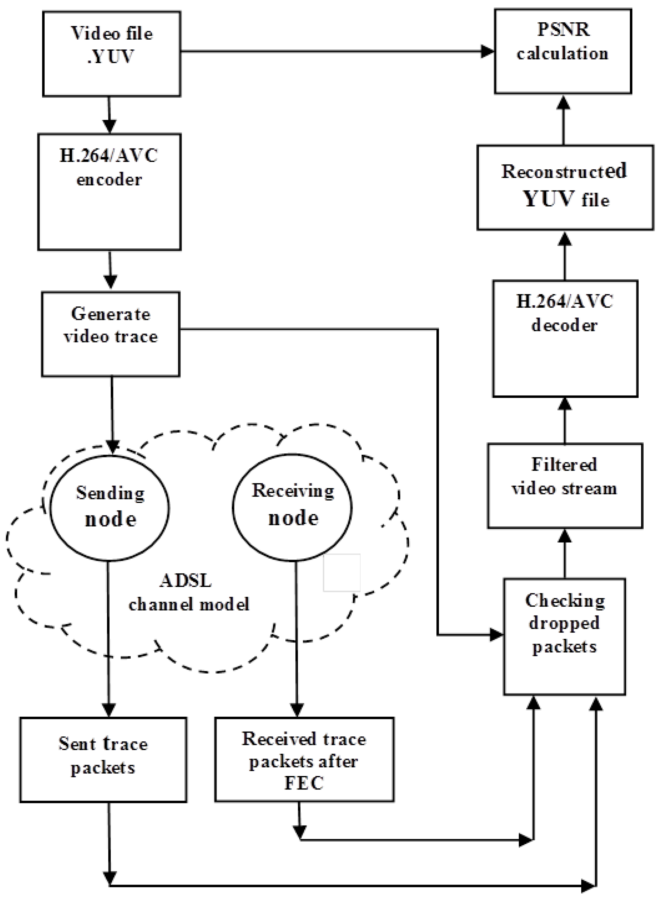
Section 3 describes the methodology employed in evaluating the application of LDGM FEC. Section 4 is a comparison across those codes in terms of the trade-offs to be made across the dimensions of latency, error recovery, severity of error conditions, and resulting video distortion. In Section 5 we review related research in this area. Finally, Section 6 makes some concluding remarks before discussing future developments of this research.

2. Channel Codes

This Section is a review of some available channel codes from the points of view of latency, computational complexity, error correction capability, and other implementation factors.

2.1. LDPC Codes

LDPC codes are linear block codes [18] characterized by parameters k, and n, which correspond to the number of bits (assuming for the moment a bit-sized symbol) of an information and code vector respectively. Therefore, the number of redundant bits is n k . The rate of such a code is represented by r = k / n , i.e., r is inversely proportional to the number of redundant symbols added.
In order to output a code vector c from an information vector u a generator matrix G is required:
c = u G
Notice that a code vector includes both input data symbols and additional parity symbols. In turn, G is created from a parity-check matrix H, which is involved in decoding when a transmission error has occurred. As the code’s name implies, matrix H is a sparse matrix with a low density of “1s” and all other entries set to zero. In general, the entries of H are filled randomly.
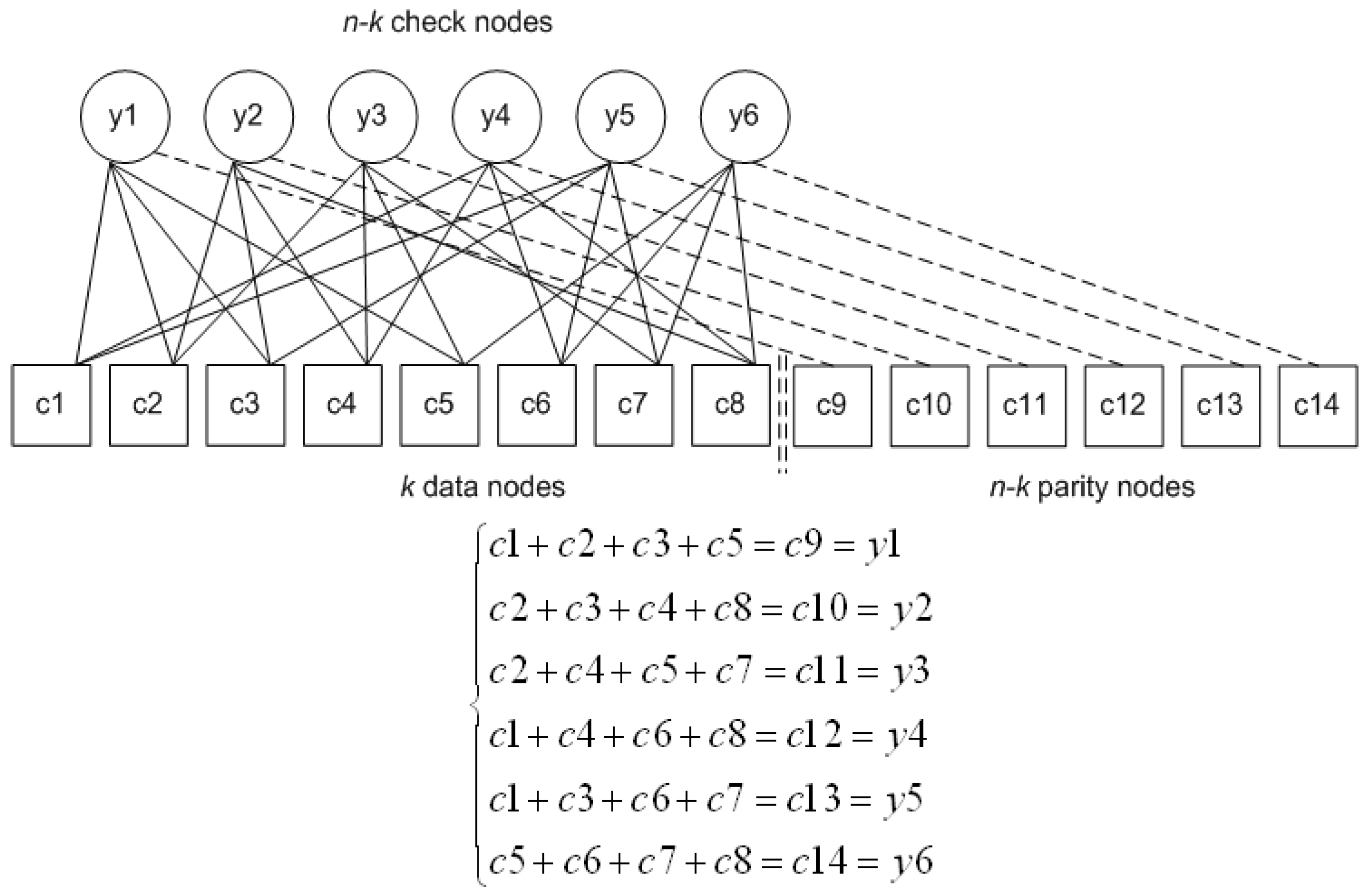
 H provides n k parity check equations that create constraints between data symbols and parity symbols. These constraints indicate which data symbols are involved in Exclusive OR (XOR) operations to form the parity symbols. Notice that, in LDPC, data symbols contribute indirectly to the creation of the parity symbols because the constraints can be combined in an XOR operation to form a parity symbol. To create G from H, H is first re-arranged in an appropriate form such that the output will be systematic. (A systematic code is one in which the information symbols are separated from the parity symbols, allowing the information symbols to be extracted without decoding if no errors are detected.) Thus, H is represented as:
H = [ P T | I n k ]
where P is a matrix of dimensions k × ( n k ) and I n k is the identity matrix of dimensions ( n k ) × ( n k ) . G is then created as:
G = [ I k | P ]
Though the “1s” in the H matrix are randomly generated, the number of “1s” in each row and each column is principally kept constant to reduce legal complexity, as mentioned in Section 1. Such an LDPC (and its lower-complexity cousin LDGM) H matrix is called regular under that constraint. For example, in a regular H matrix with three “1s” in each column, each code symbol is involved in three constraint equations. Each row represents a constraint equation. Thus, with four “1s” in a row, three data symbols are combined with a parity symbol. The constraint is then that all four symbols when XORed together will give a value of zero, hence the name parity check for matrix H.
Thus, two parameters can be defined: w c , the number of “1s” in each column; and w r , the number of “1s” in each row. For H also to be sparse requires w c ( n k ) and w r k . Then for a regular LDPC matrix:
n . w c = ( n k ) . w r
Although LDPC codes are not a Maximum-Distance Separable (MDS) code, implying that they do not offer the optimal recovery capability for a block code, they have a lower decoding computational burden compared to RS codes, owing to: the use of XOR operations to generate the redundancy when encoding; and the low density of the parity-check matrix, which results in a low number of decoding operations.
To put matrix H in the form given by equation (2) the Gauss-Jordan elimination algorithm can be used. That algorithm, in general, has complexity of order ( n k ) 3 . Depending on circumstances, the creation of matrix G from H can be performed offline. However, resulting matrix G in general is not sparse, owing to the Gauss-Jordan elimination process applied, resulting in an encoding complexity of order ( n k ) 2 , with n around 1000 in large block coding.
It is possible to rearrange matrix H into an approximately lower-triangle form [19] so that it retains its sparseness, even after Gauss-Jordan elimination, because only some of the sub-matrices are affected. The order of encoding complexity then becomes n + g 2 , where g is a small constant or scales as a small fraction of n [20]. The algorithm’s software complexity does increase as a result, whatever the theoretical computational complexity. Therefore, LDGM is an alternative way to create a sparse generator matrix, as now discussed.
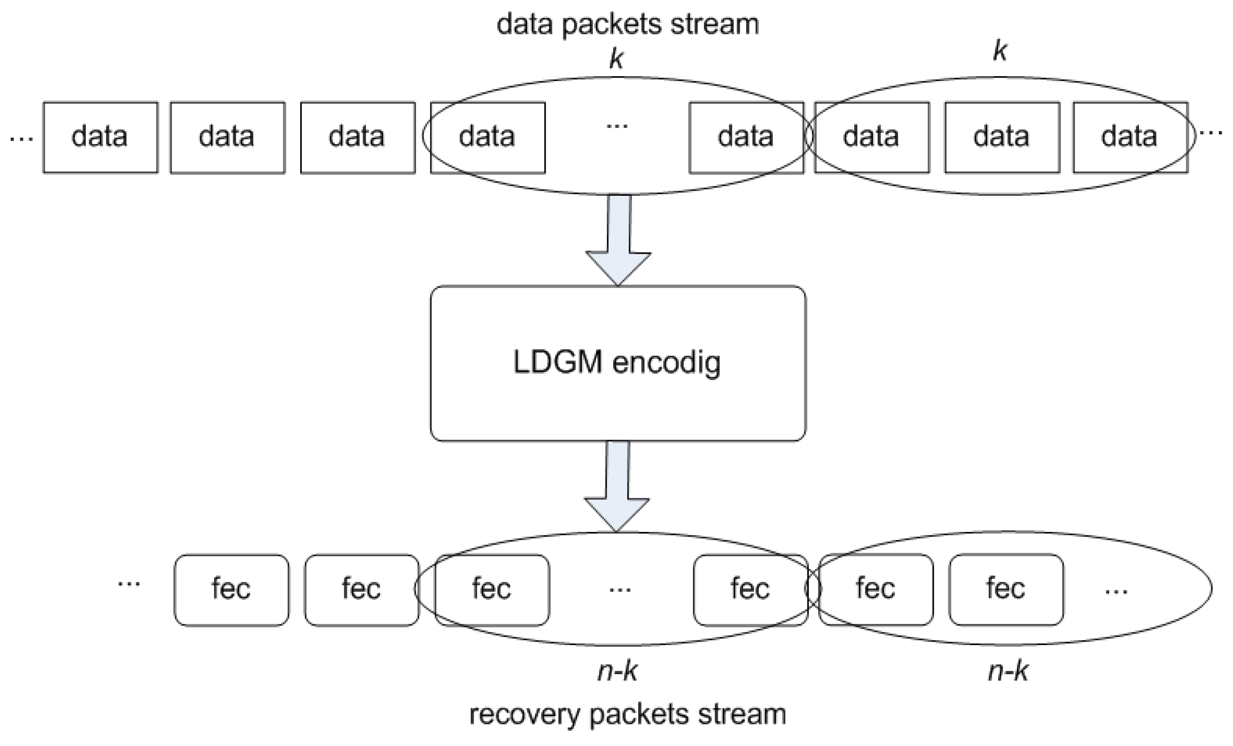
2.2. LDGM Codes

A simplified version of LDPC codes is represented by LDGM codes, for which the parity-check matrix H corresponds to the generator matrix G [13], i.e., 
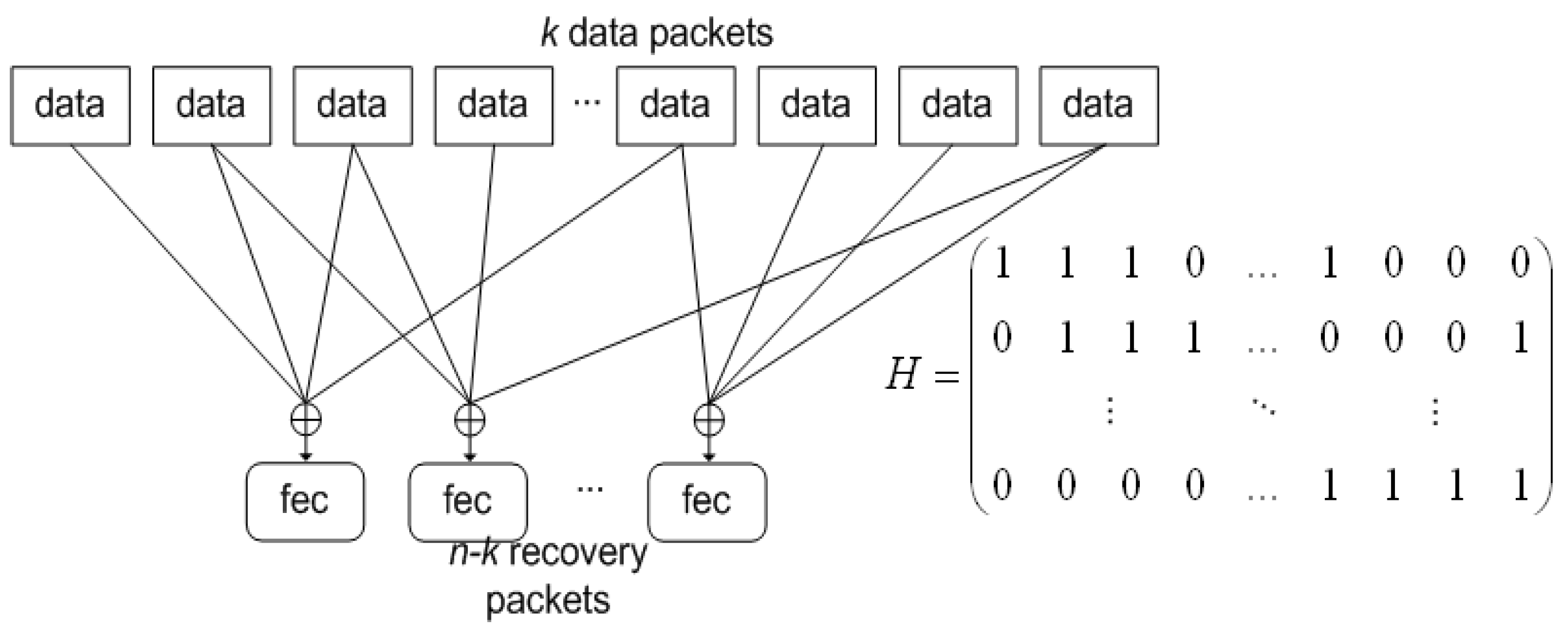
H is employed directly in encoding. In the LDGM approach, the parity-check matrix H has a size of ( n k ) × k , compared to the LDPC case in Section 2.1 of ( n k ) × n . An identity matrix of size ( n k ) × ( n k ) augments H in order to associate each parity symbol with a set of data symbols identified by H. Thus, augmented H, H , has the form:
H = [ H | I n k ]
It is interesting to compare the LDGM codes with the Staircase codes of [20] for fast encoding. Though in [20] these are called LPDC codes, they are in fact also a type of LDGM code, as the first k data symbols are combined through H. However, rather than augment H with an identity matrix, H is augmented with a diagonal matrix, P D , with just two “1s” in each row (except for just one “1” in the first row) and size ( n k ) × ( n k ) . The form of P D , which is of a descending staircase of “1s” from the viewer’s left to right, gives rise to the name “Staircase”. The form of the Staircase code matrix Hs is:
H s = [ H | P D ]
The Staircase code can be used in an iterative fashion to create the parity symbols. The author of [20] points out that this Staircase code has linear encoding complexity if account is taken of the sparseness of H. Thus, it is that LDGM codes also have linear encoding complexity. A regular LDGM code, as used in this paper, is constrained by:
k . w c = ( n k ) . w r
When encoding with H, only the first k symbols contribute to encoding, compared to the LDPC case, for which n symbols have to be processed. The disadvantage of this arrangement is that parity symbols are only protected by one subset of data symbols, implying that the error-correction capability is reduced. LDGM codes have several potential advantages despite the reduction in recovery performance: as the encoding complexity is lower than LDPC codes and decoding is similarly of low complexity, i.e., the decoding algorithms are the same, they are suited to encoding/decoding on a variety of battery-powered mobile devices; and low values of k imply that for real-time video applications such as telemedicine or video conferencing, the latency budget is considerably reduced.
There is a downside: LDGM codes have high error floors that cannot necessarily be reduced by increasing the block size. (When, after application of FEC, the bit error rate ceases to reduce with decreased Signal-to-Noise Ratio (SNR), an error floor is said to exist.) However, at least for a binary symmetric channel (BSC) it is has been analytically demonstrated [21] that concatenating two LDGM codes (applying one LDGM code after another) overcomes the onset of an error floor, while retaining LDGM’s computational complexity, provided a belief-propagation (message-passing) decoding algorithm is employed. Later work [22] confirmed the findings of [21] for a Rayleigh channel and provides analysis on how best to configure LDGM codes.
In this paper, we simulate an erasure channel, which is not necessarily open to analysis in the way a BSC is but nevertheless occurs in practice after PHY-layer error recovery fails to recover a packet. An erasure channel is distinguished by the property that the positions of corrupted symbols are known in advance, sometimes because an upper-layer protocol records the packet sequence numbers. Though a concatenated LDGM code was not used in the experiments of Section 4, video quality was still found to be good. The LDGM improvement in Section 3.2 is not intended as a remedy to high error floors, though it does improve the coding efficiency. However, as with Raptor codes [12], which already use concatenated codes, the effect of introducing concatenation is expected to be simply a linear increase in coding complexity.

2.3. Pro-MPEG COP #3

Professional-MPEG code of practice #3 (Pro-MPEG COP #3) [23] is an industry standard for video transmission protection that is widely deployed. Incoming packets are arranged in a matrix on a row-by-row basis, assuming packet-sized symbols. Redundant packets are subsequently appended to each column of the matrix and optionally to each row of packets. The packets are transmitted column-by-column, i.e., orthogonally to the way they were read into the matrix. The redundant packets are created by a byte-wise XOR operation across the packets of each column/row. This simple interleaving scheme has the advantage of convenient hardware implementations. The standard restricts the number of columns and rows to a maximum of 20.
In this paper, the one-dimensional version of Pro-MPEG COP #3 is tested in which redundant packets are only created for the columns. One-dimensional Pro-MPEG COP #3 was also selected in [10] for the reason that it is more widely deployed. The number of rows was set to four (the minimum) and the number of packets in a column to 20. This is the same configuration as employed in [24] as part of an unequal loss protection (ULP) scheme, according to the video frame type (I- B- and P-type) priority. In the current paper, for ease of comparison, ULP is not used.

2.4. RS Codes

RS codes have the MDS property, i.e., any k packets can be received to recover the k information packets, whereas around k × 1.05% of packets are needed [16] for full recovery in LDPC. RS codes are linear, cyclic codes, formed by sequences of m-bits symbols, each of which symbols belong to a finite Galois Field, i.e., GF(2 m ), where m takes values greater than two. n is set to the value 2 m 1 . If m is greater than eight the RS computational complexity can be prohibitive. Specifically, the total complexity is O( k ( n k ) × ( log ( k ) ) 2 + log ( k ) ), even when using a fast frequency-domain algorithm [25].
RS FEC in the common intra-packet approach works by grouping k packets at a time. From each of the k packets, the first m-bits are extracted to form k m-bit symbols. These k symbols are employed to generate n k redundant symbols by means of the RS algorithm. The redundant symbols are then packed as the first m-bit symbols of n k parity packets. The intra-packet algorithm continues by extracting the next set of m-bit symbols and forming n k m-bit redundant symbols and packing these as the next set of symbols in the n k parity packets.
In [26], the interleaving factor was increased by forming each m-bit symbol by extracting one bit from each of m packets in turn. This alternative inter-packet approach improves the error-recovery performance in “bursty” error conditions, as the loss of any one symbol affects only one bit per packet. However, whereas the latency budget of the intra-packet scheme is the time for k packets to arrive, in the inter-packet budget it is the time for k × m packets to arrive at the sender.

3. Methodology

This Section details the evaluation methodology employed in this paper.

3.1. Packetization with LDGM

Section 2 analyzed LDPC and its cousin channel code LDGM in terms of matrix operations. Instead advantage can be taken of the sparseness of the matrices to reduce the computational complexity. This is achievable by exploiting an alternative representation of the codes in a Tanner graph, a type of bi-partite graph. The same representation is the basis of the iterative belief propagation decoding algorithm mentioned in Section 1. A Tanner graph connects code nodes, c i , and check nodes, y i . The code nodes comprise the information data together with the parity or redundant data. The check nodes describe how the input data are XORed together but they are not output as part of the coded data stream. Figure 1 shows an example of a bi-partite Tanner graph by way of explanation. Lines connecting the information data code nodes to the check nodes indicate how the data are XORed together. (Notice that XORing corresponds to modulo 2 addition.) The summation forms the output to the n k parity code nodes. Reiterating, in an LDGM code (unlike some other codes), the parity code nodes are each derived from just one check node. The Tanner graph only indicates how the data symbols are combined. For example, if each symbol is a fixed-size data block it is the data blocks that are bitwise XORed together according to the pattern given in Figure 1 and, in general, with whatever pattern is indicated by matrix H (as matrix H is used as a generator matrix in LDGM). It should also be remarked that for LDGM codes if random generation of the “1s” in H, subject to the constraint of (7) results in a cycle of four, this cycle is removed by rearranging the matrix. Cycles of four occur when two data nodes are connected to the same two check nodes in the Tanner graph representation. The reason for this rearrangement is that cycles of four are known to result in weaker decoding performance.
Thus, in LDGM codes, a recovery packet is generated for each row of H, as the result of applying bitwise XOR operations to the data packets corresponding to the entries equal to “1” in H, as described by Figure 1. The process to do this at the data-packet level is shown in Figure 2. Equally, each row of H indicates which data packets are combined to form a FEC packet. Each row provides recovery for just one packet. Thus, if any one packet indicated by the presence of a “1” in the row is lost it can be recovered by bitwise XORing with the remaining packets together with the corresponding FEC packet. If more than one packet in a row is lost in an error burst then it is no longer possible to recover a packet using that row alone. This property can also be deduced from the equations in Figure 1. However, if more than one packet in a row has been lost it is possible to replace one or more of those packets by first using the recovery properties of other rows. Nevertheless, the recovery becomes problematic if error bursts occur, because then more rows face the loss of more than one packet. The longer the error burst the more likely that a number of rows within sparse H could be affected. This issue is returned to in Section 3.2.
To take advantage of the possibility of allowing the information data to by-pass decoding if no errors are detected, the information and parity data can be separated into two streams. The three main steps of the protection scheme are illustrated in Figure 3: (i) division of data into blocks of low k, (ii) encoding of each block of k information data packets, and (iii) the outcome of the coding for each block of k data packets then forms a set of n k packets.

3.2. Extending LDGM for “Bursty” Channels

LDGM codes are randomly generated and are not normally modified (except for minor optimizations such as removal of cycles of four) to improve their recovery capability for a particular transmission channel type. However, if an estimate of that recovery capability could be made then the parity-check matrix H could be modified to improve the protection for “bursty” channel conditions. Error bursts are common in wireless channels due to time-varying fading as the mobile user changes location. Fast fading owing to destructive interference from multipath propagation can cause short error bursts. Longer bursts can occur owing to slow fading, when the user moves into a different environment, for example, where there is shadowing from a building. Compressed video streaming is known [27] to be more susceptible to error bursts than it is to isolated errors.
The improvement to the layout of H occurs without changing its defining parameters introduced in Section, namely k, n, w c and w r . For low values of the Packet Error Rate (PER), it is reasonable to assume [24] that only one error burst occurs per block of k packets. Then for each column j in H assess all bursts starting at the packet in column j and extending by a range from 2 to n k . The assessment determines whether the packets lost in the error burst can be recovered by application of the FEC. The column-based recovery estimate (CRE) for any column j is, thus, found as:
C R E j = l = 2 m a x ( n k , n j ) F E C ( B j l )
where B j l is a burst of length l ( 2 , n k ) starting at packet j. F E C ( . ) is an indicator function taking the value 1 if the lost packets can be recovered by the LDGM code and 0 if not. Across all of H, the global recovery estimate (GRE) capability is then given by:
G R E H = j = 0 k 1 C R E ( j )
An algorithm to improve the LDGM matrix H is detailed in [28]. In this paper we informally outline the algorithm and compare error recovery with the improved LDGM matrix against original LDGM. The performance comparison can be found in Section 4.
The algorithm in a first phase works by re-arranging the entries of the columns j , j + 1 , , j + ( l 1 ) , where j = arg min ( C R E ( · ) , that is column j for which C R E ( · ) is at a minimum across the columns of H. For example, if the burst length were assumed to be four, it would attempt to re-arrange the entries within the columns j , , j + 3 . The rows of this sub-set of columns form a sub-matrix of H. Within each row of the sub-matrix, any row with only one “1” entry can be repaired, assuming no other burst affected the columns of H. Now search for rows within the sub-matrix with just two “1s”. These rows cannot be repaired, because two of the corresponding packets have been lost in the burst. However, if one of the “1s” is removed and placed in another row, that row can now be repaired. The most suitable row to move the “1” to is a row with all zero entries. This is because, by adding a “1” to that row of the sub-matrix, the “1” is placed in a position where it can be repaired.
However, by moving a “1” from one row to another H is no longer regular and does not have the benefit of fixed block sizes. Therefore, in the second and final phase of the algorithm, if within the sub-matrix a “1” has been moved from a row to another where there was previously a “0”, the reverse swap takes place at some place within H outside the sub-matrix. In that way, the constraint of equation (8) is kept. A suitable place to perform this operation is within the sub-matrix formed from columns h to h + l , where h = arg max ( C R E ( · ) ) , that is the column h for which C R E ( · ) is at a maximum across the columns of H. The heuristic behind that choice is that the range of columns starting from h already has the most resilience against packet-error bursts.
After each adjustment to H, G R E ( H ) in equation (10) is re-calculated until G R E ( H ) ceases to increase, at which point the algorithm halts. Other heuristic stopping criteria could be applied, as the behavior of G R E ( H ) is not established, though see Section 4.3.

3.3. Evaluating the Video Response

To provide a realistic evaluation of video distortion, tests used the reference video sequence Football, with plenty of motion activity, which increases the temporal compression coding dependencies. In order to judge the video distortion, a video trace was fed into a numerical simulator (refer to Figure 4) where ADSL packetization took place. After numerical simulation, data from the ADSL packets judged lost were removed from the compressed video bitstream, prior to passing through the H.264/Advanced Video Coding (AVC) [29] decoder. The resulting bitstreams (before and after LDGM repair) were compared to the YUV video input to determine the Peak Signal-to-Noise Ratio (PSNR).
To allow the gain from combining FEC with built-in error resiliency, HEVC was not used as it has limited support for error resiliency. Instead the video sequence was encoded with the H.264/AVC JM 14.2 codec in Common Intermediate Format ( 352 × 288 pixels/frame) at 30 frames/s with a Constant BitRate (CBR) of 1 Mbps. The frame structure was an initial intra-coded frame followed by all predictively-coded P-frames. Two percent intra-coded macroblocks (MBs) were included in the P-frames to guard against temporal error propagation. The IPPP…frame structure with intra-coded MBs included, is also suitable for streaming to mobile devices, as there is reduced computation because bi-predictive B-frames are no longer employed. Channel switching, for which periodic I-frames are useful, is not expected in a telemedicine or video-conferencing application. Data partitioning was also turned on at the codec as an additional form of error resilience, with constrained intra prediction also configured. These video settings conform to the recommendations of [30].

3.4. Modeling the Wireless Channel

To model adverse channel conditions across a wireless link, “bursty” errors (time correlated errors) were modeled by a Gilbert-Elliott two-state hidden Markov model [31], as illustrated in Figure 5. This channel model was introduced into the ns-2 simulator. The Gilbert-Elliott channel model itself forms a two-state Markov chain. It is based on good and bad states, the probabilities of these states, and the probabilities of the transition states between them. In the bad state, B, losses happen with higher probability, whereas in the good state, G, losses happen with lower probability.
P G G refers to the probability of being in the good state and P G B is the probability of a transition from the good state to the bad state. P B B is likewise the probability of being in the bad state and transitioning back to the same bad state. P B G refers to the probability of a transition from the bad to good state. P G G ( P B B ) can be interpreted as the probability of remaining in the good (bad) state, given that the previous state was good (bad). Conversely, P G B represents the probability that, given that the previous state was good, a transition is made from the good to the bad state. By the law of total probability, all probabilities sum to one (certainty). Therefore, we have P G G + P G B = 1 , resulting in Equation (10). A similar argument for the bad state leads to Equation (11).
P G G = 1 P G B
P B B = 1 P B G
For the stochastic process to remain stationary in time,
π G P G B = π B P B G
where π G and π B are the steady-state probabilities of being in a good or bad state respectively. The law of total probability π B = 1 π G again applies. Substituting this expression for π B into Equation (12) easily leads to:
π G = P B G P B G + P G B
Similarly, π G = 1 π B . Substituting this expression for π G into Equation (13) easily leads to:
π B = P G B P B G + P G B
Thus, the average loss rate produced by the Gilbert-Elliott channel model is
L = p G . π G + p B . π B
where p G and p B are the internal error rates of the good and bad states respectively.

4. Findings

This Section firstly compares across the candidate channel codes before investigating how the proposed LDGM method performs when applied specifically to video streams. In the experiments, the code was a regular LDGM code with degree three. The parity-check matrix was created by using the classic stochastic algorithm [32]. Decoding was based on the belief-propagation iterative algorithm mentioned in Section 1.

4.1. Comparison across Channel Codes

As described in Section 3, packet error bursts were simulated by a Gilbert-Elliott model, in which a worst-case PER for ADSL was taken to be 1% [8], i.e., the bad state of the Gilbert-Elliott model was entered on average about 1% of time. Bursts occurred randomly (Uniform distribution). Burst lengths in time are around 8 ms [8] according to the Repetitive Electrical Impulse Noise (REIN) model for ADSL channels. The packet error burst lengths (Ln), which depend on the transmission rate, were set to 15, 20, and 25. The simulation ranged over the video data from a two-hour video movie.
We have concentrated on packet bursts because, as remarked previously, it is known [27] that burst errors are more harmful to multimedia streams than are isolated errors. Moreover, a good number of studies have reported that packet error bursts are common in various types of network. A study of a campus network [33] reported that error bursts were not only common on heavily-utilized links but appeared to occur with time lengths of less than 5 s (the resolution of the packet loss detection method) on under-utilized links. UDP transport is more relevant to low-latency and interactive multimedia streams. In [34], time-stationary traces amounting to 76 h of Internet traffic were examined. The minimum sampling resolution for those traces for which a 2-state Markov model was a good fit was 160 ms, while 80 ms, 40 ms, and 20 ms resolution traces were not a good fit. However, it can be remarked that while packet loss correlations were detected, they may well have come from buffer overflows rather than the REIN noise presumed to occur in ADSL channels. In fact, [35] considered drop-tail routers to be the most likely cause of Internet packet loss bursts of about 0.1 × the round-trip-time (RTT). RTTs varied between 2 ms and 200 ms in [36]’s study. Turning to home access networks, ADSL and cable, the empirical study of [36] mainly reported on through put and latency. However, there were a few observations on packet loss. For example, for users with the same Internet Service Provider (ISP) and service plan, one user consistently had greater throughput of several hundred kB that was probably due to packet losses. The authors of [37] tested their interleaving scheme on the PlanetLab network testbed in respect to the wired Internet and over satellite links. In the wired Internet experiments, 45% of flows experienced no losses, while 10% of packet flows experienced over 50% packet losses. Packet losses of over 100 packets occurred in 8% of the packet flows. In general, packet losses occurred in bursts of less than 25 packets. In the satellite tests, packet loss conditions varied greatly over time. Burst lengths were found to be strongly peaked at 2 packets and below.
In our experiments, the ADSL packet size was set to 50 bytes (B). That size is close to the 53 B cell size of the Asynchronous Transfer Mode (ATM) [38] predominantly employed at the data-link layer over ADSL. (Only 48 bytes (B) form the payload in ATM; the remaining header bytes are heavily protected.). ADSL “Fast Track” [39] was turned on but packet interleaving to reduce further the impact of error bursts was turned off so as not to introduce additional latency. ADSL transmission rates vary according to the version of ADSL. For downstream transmission a maximum of 8 Mbps is achievable in the earliest version, rising to a projected 52 Mbps in the recent ADSL2 + + . However, it is the upstream transmission rate that is limiting for interactive video streaming and this correspondingly ranges from a maximum of 1 Mbps to a projected 5 Mbps.
In this evaluation, as previously mentioned, an erasure channel was assumed. In practice, groups of erasures would need to be detected at the application-layer if that layer was used to identify which packets forming a video bitstream had been lost. MPEG2-Transport Stream (TS) [40] (a standard way of encapsulating multimedia data) has a packet size is 188 bytes, of which four bytes form a header. The MPEG2-TS headers contain a 13-bit packet identifier, which can be employed to identify erasures. Multiple MPEG2-TS packets can be packed into RTP packets for core network transport. RTP packets also contain a sequence number in bits 16-31 of the header but up to eight MPEG-2 packets are typically contained in an RTP packet, limiting its header’s use in detecting erasures. Notice also that RFC 6363 [41] describes a framework for transporting systematic codes in two RTP streams, similarly to the arrangement already shown in Figure 3.
The coding rate, k / n , was set to 90% with n = 550. In order to make the RS intra-packet coding rate the same for Pro-MPEG COP #3 and LDGM codes, the RS parameter m was set to 6, not 8 as is more usual. For RS coding, the packet stream was grouped 80 packets at a time. The Pro-MPEG COP #3 configuration was described in Section 2.
From Figure 6, it is apparent that inter-packet RS [25] has the highest error-recovery property, which will also be higher than the standard intra-packet method. However, the industry standard Pro-MPEG COP #3 deteriorates sharply in its error recovery capability when the burst length increases. At packet burst lengths of 20 and 25 packets, LDGM provides better error recovery properties than Pro-MPEG COP #3. Moreover, the Pro-MPEG COP #3 latency budget is much longer in duration of time than LDGM because all packets in Pro-MPEG COP #3’s interleaving matrix must first be assembled at the encoder (and likewise arrive at the decoder). Similarly, for RS coding there is a latency budget of k packets at the encoder for the intra-packet version and k.m for the evaluated inter-packet version. Moreover, as previously mentioned, when using LDGM, decoding can begin at an early stage when applying the belief-propagation algorithm. The computational complexity of the RS algorithm, according to Section 2, is much higher than that of LDGM.

4.2. Impact upon Video Distortion from LDGM

In experiments in this Section, ADSL was again assumed with small packet sizes of 50 B and 100 B for each of two sets of tests respectively. The ADSL configuration was the same as in the Section 4.1. However, the results from testing with a larger 100 B packet size are also included in this Section, bringing the packet size closer to that of an MPEG2-TS packet. For 100 B packets a downstream bitrate of 10 Mbps was configured, with a per-packet link latency of around 100 ms. For 50 B packets and two-way communication a 1 Mbps effective datarate was assumed, with a per-packet link latency of around 10 ms. As previously, the PER was set 1% [8], though with burst lengths of 8 and 10 packets for the 50 B and 100 B packets respectively. Thus, the channel conditions were more benign than in the previous Section’s experiment.
To counter error bursts, the packet block size was set to k = 300, 400. The number of redundant packets, n k , was somewhat reduced to 9% of the whole. The latency budget remains well below the previously mentioned 1000 packets length of large block coding schemes.
Table 1 shows five sample runs each with a different seed and the resulting mean PSNR. (The code seed was set to 40, 50, 70, 80, and 90 for 1–5 respectively.) The mean gain after application of LDGM was between 1 and 2 dB with the video PSNR approaching a level suitable for broadcast. Interestingly from the point of view of latency, increasing the block size does not necessarily lead to a reduction in video distortion.
For the larger packet size and the greater bandwidth of Table 2, the video distortion reduction is more consistent and is 3–4 dB. The consistency is due to a constant code seed of 50 throughout. Notice that in view of the larger 100 B packet size the block sizes are decreased. Again a larger block size appears not to lead to an advantage. This effect may be linked to the pattern of packet burst erasures. Comparing the 100 B PSNR gain to that of 50 B packets, for the latter the FEC gain appears to have saturated, suggesting a reduced FEC rate is possible.

4.3. Comparing LDGM with Error Burst Improved LDGM

This Section seeks to find the improvement were the algorithm of Section 3.2 to be employed. Settings of k = 80 , and n = 100 packets, as recommended in [23] were chosen, as this very small value of k minimizes latency, whereas n is chosen for medium redundancy. As before, the parity check matrix was created by the classic stochastic algorithm of [32]. w c and w r were again set to three and four respectively. 2000 blocks of packets were sent to assure data confidence.
Table 3 and Table 4 record the worst, best, and average recovery capabilities across 50 different matrices, for LDGM and improved LDGM respectively. Burst lengths of 5 and 10 packets were simulated with the two given PERs. Average recovery capability is better in all cases for improved LDGM, which implies that implementing this algorithm can improve the mean objective video quality.

5. Related Work

The impact of impulse noise on an ADSL2+ link is documented in [42]. Evidently there is severe “blockiness”, where runs of macroblocks (MBs) have been lost and error concealment at the codec decoder has failed to replace the MBs in an unobtrusive manner.
In [16], a simple 2D FEC code (with similarities to Pro-MPEG COP #3), RS codes, and LDPC were evaluated by embedding them in Linux RTP protocol stacks that included RTP packetization with IP/UDP headers. Packet erasures were uniformly distributed. The coding rate was high at 2/3. The authors reported that above 30% PERs, no codes could repair all packets but LDPC was only slightly worse than RS in error recovery. The simple 2D FEC code was noticeably worse than both LDPC and RS. Comparing latencies, RS codes introduced maximum average delay of 544 ms, followed by LDPC with 1000 block lengths at 402 ms and the simple 2D FEC codes at around 50 ms. Lower block lengths for LDPC reduced latency but decreased error recovery. These results confirm that a compromise code, such as LDGM (or low block length LDPC), is a good option for interactive video. Computational overhead for the simple 2D FEC code and LDPC remained below 8% whatever the PER while as the error rate increased RS code computational overhead climbed steeply.
As part of the OpenFEC project, [43] examined the same codes as in [16] but with measured error traces from ADSL links rather than the random drops of [16]. These results confirmed those of [16] for random losses but showed that even at loss rates below 10% and with a code rate of 2/3, when error bursts occurred not all packets could be recovered. As in [16] an LDPC code with a block length as low as 170 was found to be competitive with RS codes in error recovery terms. Because not all packets could be recovered even at low loss rates, the ability to retransmit was recommended, which is also the recommendation of [29].
In [32], a number of interesting points of comparison are made between some of the channel codes mentioned herein. The main limitation of the LPDC family of codes in comparison to rateless non-patented online codes [44] is that they are not rateless in the sense that the maximum number of parity packets must be defined in advance. LDPC is further disadvantaged, compared to rateless and LDGM codes in that it has to store all the source parity packets during the encoding process. The family of codes performs most efficiently when the FEC overhead is low to medium. Staircase LDGM codes were preferred by the authors’ of [32] but they employed large block sizes (as they had in [13]) and were unaware of possible improvements such as that of Section 3.2.
The authors of [39] considered packet interleaving as an alternative response to bursty losses. As in Pro-MPEG COP #3 (refer to Section 2.3) the intention was to spread packet error bursts so that they no longer affect consecutive packets of the source packet stream. Unlike Pro-MPEG COP #3, channel coding was not incorporated into the interleaving scheme. Instead, packet interleaving was introduced at the IP-packet level irrespective of content. However, in [45], the authors demonstrate that if interleaving is also introduced into rate-controlled streams then the possibility exists of an adverse interaction with the congestion control algorithm. For an interleaving block of 48 UDP/IP packets, the impact on end-to-end latency was estimated to be an acceptable 65 ms. Smaller interleaving block sizes could be employed, depending on error burst conditions. The scheme was most appropriate to the small burst-length conditions present in satellite links. In [46], packet interleaving took place before video compression. Though error resilience was improved, the loss of temporal redundancy, owing to interleaving before the codec, resulted in a degradation of coding efficiency. Interleaving of base-layer and enhancement-layer packets in scalable coding does not suffer from the same weakness and in [47], along with other techniques, resulted in greater resistance to error bursts. The work in [24] dynamically introduced Pro-MPEG COP #3 into an RTP video packet stream. Depending on bitrate constraints and the channel conditions, selected video frames were protected. In particular, I-frames were protected because of their impact on later frames.
Apart from interleaving, network coding has also been deployed [48] to counter error bursts occurring in wireless multi-hop networks. Alternatively, if it is possible to adaptively route packets based on measured link conditions, as it is with the Cognitive Packet Network [49], then multimedia streams can gain in quality and become more resilient to error bursts. Again, in content-aware networks, transmitting redundant packets can counter packet losses [50].

6. Conclusions

This study has shown study that industry-standard 2D parity codes underperform in terms of combined latency and error recovery. RS codes are attractive in terms of error recovery but are not so attractive for low-latency applications of video streaming. Whenever there is interactivity RS codes at the application layer potentially result in a lack of synchronization between two communicating parties. This problem arises owing to their computational complexity and the need to apply them in an interleaving mode, which increases the latency budget. As an alternative, this paper proposes that LDGM codes with small block lengths represent a natural candidate for low-latency interactive video streaming and, as results quoted in this paper indicate, can lead to up to a 4 dB reduction in video distortion for active sports sequences. The coding overhead is just a 9% increase in datarate. Furthermore, by rearranging columns of the parity-check matrix with the least error-recovery properties it is possible to improve the average response to error bursts. Given that rateless codes may have patents applied, LDGM codes offer a further commercial advantage, because licensing fees no longer apply. The latter advantage makes LDGM codes suitable for applications such as telemedicine in which video streaming does not generate a compensating revenue stream.
Future work will check the performance of these codes against video content other than the sports sequences so far investigated. The HEVC codec is aimed at high definition (HD) video and, hence, the HD video should also be investigated, confirming the real-time performance. In general, as the number of packets in HD video communication is much larger than for standard definition (SD) video the impact of any one packet loss in terms of error propagation is expected [51] to be less than that for SD video. Consequently, a pure FEC technique such as in this paper may be even more effective for HD video. In general, the real-time transmission and FEC coding time will scale linearly according to the number of packets in an HD video frame relative to an SD frame. Thus in [44], there were 31 and 68 rows of macroblocks for SD and HD respectively, with coding at rates of 4 and 16 Mbps respectively using H.264/AVC. HEVC [1] has approximately 50% more coding efficiency than H.264/AVC, which clearly saves bandwidth. However, paradoxically, increased coding efficiency, reduces the error protection arising from LDGM FEC (at the same rate as applied to H.264/AVC streams) because greater coding efficiency implies greater dependencies between the bits in the video bitstream.

Author Contributions

Laith Al-Jobouri and Filippo Casu were chiefly responsible for the experimental contributions in this paper, whereas Julián Cabrera and Martin Fleury contributed to theoretical development. Martin Fleury was also responsible for the presentation of this paper.

Conflicts of Interest

The authors declare no conflict of interest.

References

  1. Ohm, J.; Sullivan, G.; Schwarz, H.; Tan, T.K. Comparison of the coding efficiency of video coding standards—Including High Efficiency Video Coding (HEVC). IEEE Trans. Circuits Syst. Video Technol. 2012, 22, 1669–1684. [Google Scholar] [CrossRef]
  2. Schierl, T.; Hannuksela, M.M.; Wang, Y.-W.; Wenger, S. System layer integration of High Efficiency Video Coding. IEEE Trans. Circuits Syst. Video Technol. 2012, 12, 1871–1884. [Google Scholar] [CrossRef]
  3. Panayides, A.; Pattichis, M.S.; Pattichis, C.S.; Loizou, C.P.; Pantziaris, M.; Pitsillides, A. Robust and efficient ultrasound video coding in noisy channels using H.264. In Proceedings of the IEEE Annual International Conference of Engineering in Medicine and Biology Society, Minneapolis, MN, USA, 3–6 September 2009; pp. 5143–5146.
  4. Bossen, F.; Bross, B.; Sühring, K.; Flynn, D. HEVC complexity and implementation analysis. IEEE Trans. Circuits Syst. Video Technol. 2012, 22, 1685–1696. [Google Scholar] [CrossRef]
  5. World Broadband Statistics: Q2; Point Topic Ltd: London, UK, 2012.
  6. British Telecom (BT) Wholesale. REIN—Repetitive Electrical Impulse Noise Customer Introduction; Version 1.0; Britich Telecommunications plc: London, UK, 2013. [Google Scholar]
  7. Ghanbari, M. Standard Codecs: Image Compression to Advanced Video Coding; Institute of Electrical Engineers (now IET): Stevenage, UK, 2003. [Google Scholar]
  8. Luby, M.; Stockhammer, T.; Watson, M. Application layer FEC in IPTV services. IEEE Commun. Mag. 2008, 46, 94–101. [Google Scholar] [CrossRef]
  9. Lamoriniere, C.; Nafaa, A.; Murphy, L. Dynamic switching between adaptive FEC protocols for reliable multi-source streaming. In Proceedings of IEEE GLOBECOM, Honolulu, HI, USA, 30 November–4 December 2009.
  10. Begen, A.C. Error Control for IPTV over xDSL networks. In Proceedings of the IEEE International Conference on Consumer Communications and Networking Conference, Las Vegas, NE, USA, 10–12 January 2008; pp. 632–637.
  11. Jokela, T.; Lehtonen, E. Reed-Solomon decoding algorithms and their complexities at the DVB-H link-layer. In Proceedings of the Fourth IEEE International Symposium on Wireless Communication Systems, Trondheim, Norway, 17–19 October 2007; pp. 752–756.
  12. Shokrollahi, A.; Luby, M. Raptor codes. Found. Trends Commun. Inf. Theory 2009, 6, 213–322. [Google Scholar] [CrossRef]
  13. Rizzi, L. Effective erasure codes for reliable computer communications protocols. ACM Sigcomm Comput. Commun. Rev. 1997, 27, 24–36. [Google Scholar] [CrossRef]
  14. Roca, V.; Khalluf, Z.; Labouré, J. Design and evaluation of an LDGM large block FEC codec. In Proceedings of the Fifth International Workshop on Networked Group Communications, Munich, Germany, 16–19 September 2003.
  15. Pullano, V.; Skupin, R.; Corazza, G.E.; Hellge, C.; Schierl, T. Modeling effects of impulse noise on application-layer FEC in DSL channels. In Proceedings of the IEEE International Symposium on Broadband Multimedia Systems and Broadcasting, London, UK, 5–7 June 2013.
  16. Matsuzono, K.; Detchart, J.; Cunche, M.; Roca, V.; Asaeda, H. Performance analysis of a high-performance real-time application with several AL-FEC schemes. In Proceedings of the IEEE Local Computer Networks, Denver, CO, USA, 11–14 October 2010.
  17. Luby, M.; Mitzenmacher, M.; Shokrollahi, A.; Spielman, D. Improved low-density codes using irregular graphs. IEEE Trans. Info. Theory 2001, 47, 585–598. [Google Scholar] [CrossRef]
  18. Ryan, W.E. An introduction to LDPC Codes. In CRC Handbook for Coding and Signal Processing for Magnetic Recording Systems; Vasic, B., Kurtas, E., Eds.; CRC Press: Boca Raton, FL, USA, 2004. [Google Scholar]
  19. Richardson, T.J.; Urbanke, R.L. Efficient encoding of Low-Density Parity-Check codes. IEEE Trans. Inform. Theory 2001, 47, 638–656. [Google Scholar] [CrossRef]
  20. MacKay, D.J. Information Theory, Inference, and Learning Algorithms; Cambridge University Press: Cambridge, UK, 2003. [Google Scholar]
  21. Garcia-Frias, J.; Zhong, W. Approaching Shannon performance by iterative decoding of linear codes with Low-Density Generator Matrix. IEEE Commun. Lett. 2003, 7, 266–269. [Google Scholar] [CrossRef]
  22. González-López, M.; Vázquez-Araújo, F.J.; Castedo, L.; Garcia-Frias, J. Serially-concatenated Low-Density Generator Matrix (SCLDGM) codes for transmission over AWGN and Rayleigh fading channels. IEEE Trans. Wirel. Commun. 2007, 6, 2753–2758. [Google Scholar] [CrossRef]
  23. Pro-MPEG Forum. Transmission of Professional MPEG-2 Transport Streams over IP Networks; Code of Practice #3 Release 2; SMPTE: Whiteplains, NY, USA, 2004. [Google Scholar]
  24. Díaz, C.; Cabrera, J.; Jaureguizar, F.; García, N. A video-aware FEC-based unequal loss protection system for video streaming over RTP. IEEE Trans. Consum. Electron. 2011, 57, 523–531. [Google Scholar] [CrossRef]
  25. Lacan, J.; Roca, V.; Peltotalo, J.; Peltotalo, S. Reed-Solomon Forward Error Correction (FEC) Schemes; IETF RFC 5510; IETF Trust: Reston, VA, USA, 2009. [Google Scholar]
  26. Casu, F.; Cabrera, J.; Jaureguizar, F.; García, N. Inter-packet symbol approach to Reed-Solomon FEC codes for RTP-multimedia stream protection. In Proceedings of the IEEE Symposium on Computers and Communications, Corfu, Greece, 28 June–1 July 2011; pp. 49–54.
  27. Liang, Y.J.; Apostolopoulos, J.; Girod, B. Analysis of packet loss for compressed video: Effect of burst losses and correlation between error frames. IEEE Trans Circuits Syst. Video Technol. 2008, 18, 861–873. [Google Scholar] [CrossRef]
  28. Casu, F.; Cabrera, J.; Jaureguizar, F.; Garcia, N. A protection scheme for multimedia packet streams in bursty packet loss networks based on small block low-density parity-check codes. EURASIP J. Wirel. Commun. Netw. 2015, 187, 1–14. [Google Scholar] [CrossRef] [Green Version]
  29. Wenger, S. H.264/AVC over IP. IEEE Trans. Circuits Syst. Video Technol. 2003, 13, 645–655. [Google Scholar] [CrossRef]
  30. Al-Jobouri, L.; Fleury, M.; Ghanbari, M. Engineering wireless broadband access to IPTV. J. Vis. Commun. Image Represent. 2014, 25, 1493–1506. [Google Scholar] [CrossRef]
  31. Jiao, C.; Schwiebert, L.; Xu, B. On modeling the packet error statistics in bursty channels. In Proceedings of the IEEE Conference on Local Computer Networks, Tampa, FL, USA, 6–8 November 2002; pp. 534–541.
  32. Roca, C.; Neumann, C.; Cunche, M.; Laboure, J. LDPC-Staircase/LDPC-Triangle/LDGM Codec Reference Implementation. Available online: http://planete-bcast.inrialpes.fr (accessed on 18 May 2016 ).
  33. Chung, S.; Agrawal, D.; Kim, M.; Hong, J.; Park, K. Analysis of bursty packet loss characteristics on underutilized links using SNMP. In Proceedings of the IEEE/IFIP End-to-End Monitoring Techniques and Services Workshop, San Diego, CA, USA, 3 October 2004; pp. 164–176.
  34. Yajnik, M.; Moon, S.; Kurose, J.; Towsley, D. Measurement and modelling of the temporal dependence in packet loss. In Proceedings of IEEE INFOCOM, New York, NY, USA, 21–25 March 1999; pp. 345–352.
  35. Wei, D.X.; Cao, P.; Low, S.H. Packet loss burstiness: Measurements and implications for distributed applications. In Proceedings of IEEE International Parallel and Distributed Processing Symposium, Nice, France, 26–30 March 2007; pp. 1–8.
  36. Sundaresan, S.; de Donato, W.; Feamster, N.; Teixeira, R.; Crawford, S.; Pescapé, A. Measuring home broadband performance. Commun. ACM 2012, 55, 100–109. [Google Scholar] [CrossRef]
  37. Botta, A.; Pescapé, A. IP packet interleaving for UDP bursty losses. J. Syst. Softw. 2015, 109, 177–191. [Google Scholar] [CrossRef]
  38. De Prycker, M. Asynchronous Transfer Mode Solutions for Broadband ISDN; Prentice Hall: Upper Saddle River, NJ, USA, 1993. [Google Scholar]
  39. Goralski, W.J. ADSL and DSL Technologies (Standards & Protocols), 2nd ed.; McGraw-Hill: Boston, MA, USA, 2001. [Google Scholar]
  40. Hwang, J.-N. Multimedia Networking: From Theory to Practice; Cambridge University Press: Cambridge, UK, 2009. [Google Scholar]
  41. Watson, M.; Begen, A.; Roca, V. Forward Error Correction (FEC) Framework. Tech. Report. RFC 6363. 2011. Available online: http://www.ietf.org/rfc/rfc6363.txt (accessed on 18 May 2016).
  42. Krejčí, J.; Zeman, T. Influence of noise on IPTV over xDSL. In Proceedings of the 16th International Conference on Systems, Signals and Image Processing, Chalkida, Greece, 18–20 June 2009.
  43. Ellis, M.; Pezaros, D.P.; Perkins, C. Performance analysis of AL-FEC for RTP-based streaming video traffic to residential users. In Proceedings of the IEEE 19th International Packet Video Workshop, Munich, Germany, 10–11 May 2012.
  44. Maymoukov, P. Online Codes; Research report TR2002-833; New York University: New York, NY, USA, 2002. [Google Scholar]
  45. Botta, A.; Pescapé, A. IP Packet Interleaving from Theory to Practice; Research Report TR-DIS-INT-7-2009; University of Napoli Federico II: Naples, Italy, 2009. [Google Scholar]
  46. Claypool, M.; Zhu, Y. Using interleaving to ameliorate the effects of packet loss in a video stream. In Proceedings of the IEEE International Conference on Distributed Computing Systems Workshops, Providence, RI, USA, 19–22 May 2003; pp. 508–513.
  47. Chin, S.K.; Braun, R. Improving video quality using packet interleaving, randomisation and redundancy. In Proceedings of the IEEE International Conference on Local Computer Networks, Tampa, FL, USA, 14–16 November 2001; pp. 405–413.
  48. Cui, H.; Qian, D.; Zhang, X.; Wu, Y.; Wang, L. Network coding-based rate allocation and bursty loss protection for video streaming over wireless multi-hop networks. In Proceedings of the IEEE International Conference on Computers and Information Technology, Savar, Bangladesh, 27–29 October 2012; pp. 684–689.
  49. Wang, I.; Gelenbe, E. An implementation of voice over IP in the cognitive packet network. In Proceedings of the 29th International Symposium on Computer and Information Sciences, Krakow, Poland, 27–28 October 2014; pp. 33–40.
  50. Han, D.; Anand, A.; Akella, A.; Sesshan, S. Rpt: Re-architecting loss protection for content-aware networks. In Proceedings of the USENIX Symposium on Networked Systems Design and Implementation, San Jose, CA, USA, 25–27 April 2012; pp. 71–84.
  51. Argyopoulos, S.; Raake, A.; Garcia, M.-N.; List, P. No reference bit stream model for video quality assessment of H.264/AVC video based on packet loss visibility. In Proceedings of the IEEE International Conference on Acoustics, Speech, and Signal Processing, Prague, Czech Republic, 27–28 May 2011; pp. 1169–1172.
Figure 1. Example Low-Density Generator Matrix (LDGM) bipartite graph.
Computers 05 00009 g001
Figure 2. Forward Error Correction (FEC) generation. Protection operation for a block of k information data packets.
Computers 05 00009 g002
Figure 3. Example of a packetized protection scheme based on LDGM codes.
Computers 05 00009 g003
Figure 4. Peak Signal-to-Noise Ratio (PSNR) evaluation framework.
Computers 05 00009 g004
Figure 5. Gilbert-Elliott model.
Computers 05 00009 g005
Figure 6. Percentage of recovered packets with Packet Error Rate (PER) = 1% and increasing packet burst lengths (Ln) for three channel codes.
Computers 05 00009 g006
Table 1. Objective video PSNR for 50 B packets before and after FEC.
Before FEC12345Mean PSNR (dB)
k = 30035.5335.0838.6336.1437.3736.55
k = 40034.4637.6638.5436.4039.0037.21
After FEC12345Mean PSNR (dB)
k = 30037.3339.0039.0037.5737.8438.15
k = 40036.9137.7639.0037.6439.0038.06
Table 2. Objective video PSNR for 100 B packets before and after FEC.
Before FEC12345Mean PSNR (dB)
k = 20034.5333.9534.9134.9335.6434.79
k = 30036.5436.4133.8134.6932.8434.86
After FEC12345Mean PSNR (dB)
k = 20038.2236.6739.0039.0038.8638.35
k = 30038.8536.5539.0038.8837.3538.13
Table 3. Recovery capability of LDGM.
Ln = 5
PER = 1%
Ln = 5
PER = 5%
Ln = 10
PER = 1%
Ln = 10
PER = 5%
Max.87%71%63%45%
Min.77%62%49%35%
Avg.83%67%55%41%
Table 4. Recovery capability of improved LDGM.
Ln = 5
PER = 1%
Ln = 5
PER = 5%
Ln = 10
PER = 1%
Ln = 10
PER = 5%
Max.90%73%67%50%
Min.81%67%52%42%
Avg.85%70%58%44%

