
Approximator: A Software Tool for Automatic Generation of Approximate Arithmetic Circuits


School of Computer Science and Engineering, Nanyang Technological University, 50 Nanyang Avenue, Singapore 639798, Singapore
*
Author to whom correspondence should be addressed.
Computers 2022, 11(1), 11; https://doi.org/10.3390/computers11010011
Submission received: 8 November 2021
/
Revised: 20 December 2021
/
Accepted: 4 January 2022
/
Published: 8 January 2022
(This article belongs to the Special Issue Feature Paper in Computers)
Abstract
:Approximate arithmetic circuits are an attractive alternative to accurate arithmetic circuits because they have significantly reduced delay, area, and power, albeit at the cost of some loss in accuracy. By keeping errors due to approximate computation within acceptable limits, approximate arithmetic circuits can be used for various practical applications such as digital signal processing, digital filtering, low power graphics processing, neuromorphic computing, hardware realization of neural networks for artificial intelligence and machine learning etc. The degree of approximation that can be incorporated into an approximate arithmetic circuit tends to vary depending on the error resiliency of the target application. Given this, the manual coding of approximate arithmetic circuits corresponding to different degrees of approximation in a hardware description language (HDL) may be a cumbersome and a time-consuming process—more so when the circuit is big. Therefore, a software tool that can automatically generate approximate arithmetic circuits of any size corresponding to a desired accuracy would not only aid the design flow but also help to improve a designer’s productivity by speeding up the circuit/system development. In this context, this paper presents ‘Approximator’, which is a software tool developed to automatically generate approximate arithmetic circuits based on a user’s specification. Approximator can automatically generate Verilog HDL codes of approximate adders and multipliers of any size based on the novel approximate arithmetic circuit architectures proposed by us. The Verilog HDL codes output by Approximator can be used for synthesis in an FPGA or ASIC (standard cell based) design environment. Additionally, the tool can perform error and accuracy analyses of approximate arithmetic circuits. The salient features of the tool are illustrated through some example screenshots captured during different stages of the tool use. Approximator has been made open-access on GitHub for the benefit of the research community, and the tool documentation is provided for the user’s reference.
1. Introduction
Approximate computing enables improvement in speed, reductions in area and power, and savings in energy compared to accurate computing at the expense of an acceptable loss in the accuracy of results [1]. There are many practical applications that are inherently error-resilient, and they have been considered as suitable candidates to evaluate the efficacy and practicality of approximate computing. Examples of such practical applications include multimedia [2], low-power graphics processing [3], memory for multi-core processors [4], the hardware implementation of neural networks for machine learning and artificial intelligence [5], software engineering [6], memory storage [7], big data mining and analytics [8], and neuromorphic computing [9]. Approximate computing broadly covers hardware, software, and memory storage, and approximate hardware includes approximate arithmetic circuits [10] and approximate logic circuits [11]. Within the domain of approximate arithmetic circuits, the design of approximate adders and multipliers has attracted significant attention [12], which is understandable given that addition and multiplication are frequently performed in microprocessors and digital signal processors. For example, in [13], it was found that additions constituted nearly 80% of the operations in an ARM processor’s arithmetic and logic unit, and it was noted in [14] that adders and multipliers contributed to about 80% of the total power consumption of a fast Fourier transform processor.
This paper discusses approximate adders and multipliers. Approximate adders are categorized into two types: Static Approximate Adders (SAAs) and Dynamic Approximate Adders (DAAs). SAAs have a fixed approximation, and they could enable significant reductions in delay, area, and power compared to accurate adders for an increase in the approximation. However, prior knowledge of the target application could be useful to determine an optimal approximation for an SAA. On the other hand, DAAs have a flexible approximation and could be configured to produce an approximate or accurate results on demand, i.e., the accuracy of results could be adjusted as per need and prior knowledge about a target application may not be necessary. However, to achieve this, DAAs incorporate additional error detection and correction logic to facilitate a variable approximation, which forms a design overhead. Furthermore, multiple computational cycles might be required to achieve a result that corresponds to a desired accuracy in a DAA. These two tend to negatively impact the design metrics of DAAs in general. In [15], for a digital video-encoding application, it was observed that the savings in power achieved by an SAA over an accurate adder is comparable with a DAA.
Many multiplier architectures such as Braun array, Booth algorithm, Wallace tree, Baugh Wooley algorithm, and the Dadda tree are available for unsigned and signed multiplication [16]. These accurate multiplier architectures have been modified to obtain approximate multiplier architectures in the literature [17]. With respect to unsigned multiplication, and especially for small multiplications that are typically encountered in digital image processing, the Braun array multiplier (BAM) [18] is preferable because it has a simple and regular structure. Moreover, BAM allows for easy pipelining to increase the throughput as required. Approximate (array) multiplier architectures can be derived by making vertical and/or horizontal cuts in an accurate BAM [19] and assigning different combinations of binary constants to the dangling internal inputs and dangling product bits.
In this article, we describe Approximator, which is a software tool developed to automatically generate Verilog HDL codes of approximate adders and multipliers of any size, corresponding to the following approximate arithmetic circuit architectures proposed by us: approximate adders (HEAA [20], HOERAA [21], HOAANED [22], and M-HERLOA [23]) and approximate (array) multipliers (AAM01 [24,25]). Though we proposed three approximate array multiplier architectures in [24], among them AAM01 [25] (also called PAAM01 [24]) was found to have better optimized error characteristics, and its superior performance was confirmed for a couple of digital image processing applications, namely digital image denoising and digital image blending. Hence, we decided to only incorporate AAM01 into Approximator. The approximate adder and multiplier architectures comprising Approximator correspond to static approximation.
Approximator has been made open for access on GitHub for the benefit of the research community and a beta version of the tool is available for free download [26]. Documentation about the tool is also provided for a user’s reference [27]. Approximator has been made available in a convenient graphical user interface (GUI) format for ease of use by an end-user. Approximator asks for input specifications from a user to: (i) generate Verilog HDL codes of approximate adders, (ii) generate Verilog HDL codes of approximate multiplier, (iii) perform error analysis of approximate arithmetic circuits, and (iv) perform accuracy analysis of approximate arithmetic circuits.
The rest of the article is structured as follows. Section 2 and Section 3 describes the approximate adders and the approximate (array) multiplier, respectively, which form a part of Approximator. Next, the development and working principle of the GUI version of Approximator are described in Section 4 through some example screenshots. Finally, Section 5 concludes the article.
2. Approximate Adders
In this section, the architectures of our approximate adders are first described. Secondly, the usefulness of the approximate adders for a digital image processing application is demonstrated. Thirdly, the error characteristics of approximate adders are discussed and popular error metrics are provided. Lastly, the design metrics of accurate and approximate adders corresponding to FPGA- and ASIC-based implementations are given.
2.1. Approximate Adders—Architectures
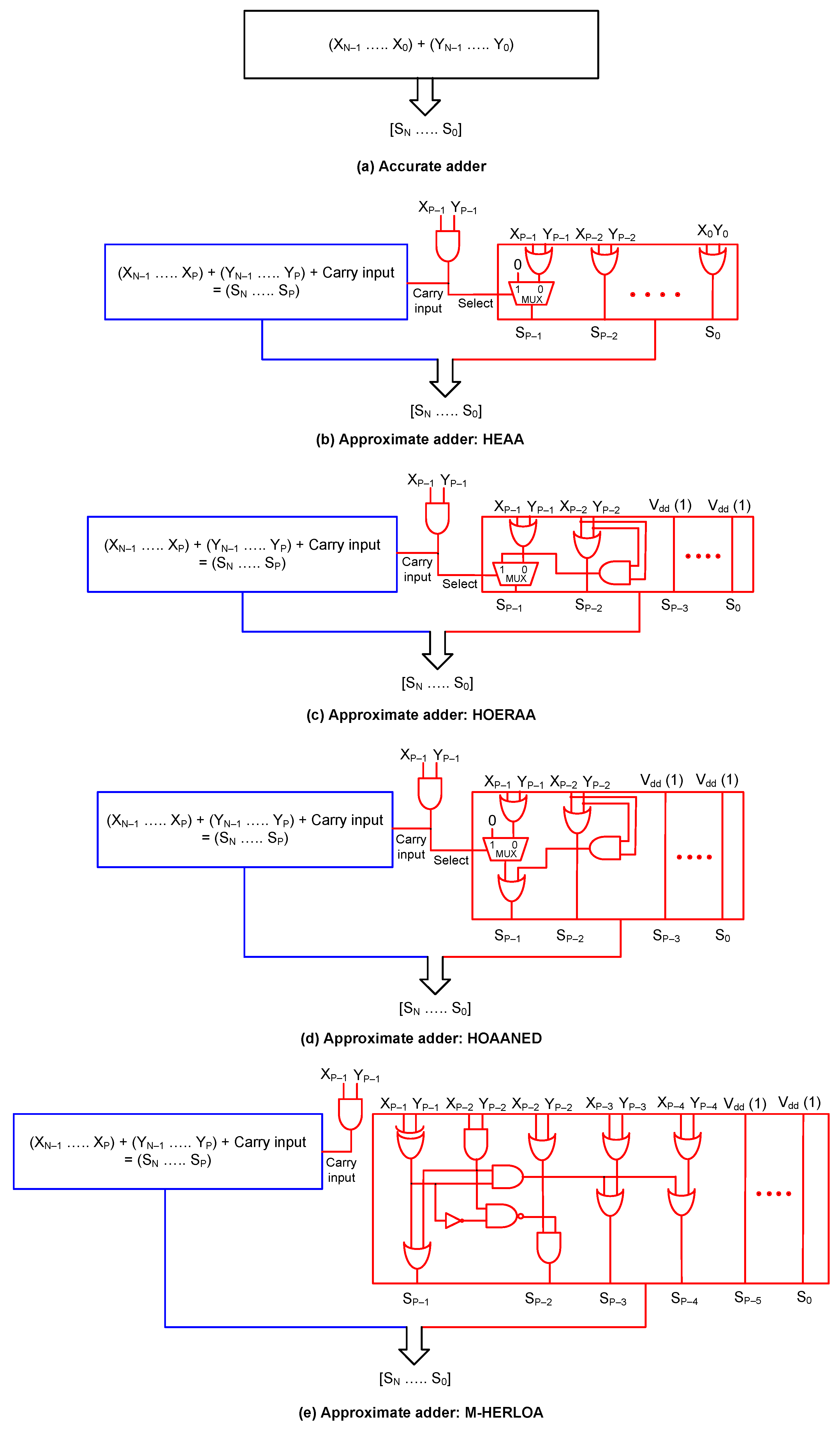
An N-bit (static) approximate adder typically consists of an inexact part that inaccurately adds P least significant bits and an exact part that accurately adds (N–P) more significant bits [28]. The value of P is best determined based on the target application, and the logic design of the inexact part depends on the type of the approximate adder used. In the inexact part of the approximate adders, different types of logic operations such as AND, OR, NAND, and EXOR are performed to produce the least significant sum bits. Accurate addition is performed in the exact part, and a high-speed adder may be used for this purpose. For an FPGA-based implementation, the native accurate FPGA adder can be used, and for an ASIC-type standard cell-based implementation, a carry look-ahead adder (CLA) may be used. Hence, the exact part of the approximate adders can be realized in the same fashion, and the implementation of the inexact parts would alone differ.
Figure 1a shows the block schematic of the accurate adder, and Figure 1b–e show the block schematics of approximate adders, i.e., HEAA, HOERAA, HOAANED and M-HERLOA, that form a part of Approximator. In Figure 1, the inexact parts of approximate adders are shown in red and the exact parts are shown in blue. X and Y represent the adder inputs, with subscripts (N−1) and 0 denoting the Most Significant Bit (MSB) and the Least Significant Bit (LSB), respectively. S represents the sum output of the adder, with subscripts N and 0 denoting the MSB and the LSB, respectively. In HEAA, HOERAA, HOAANED, and M-HERLOA, there is a carry input provided to the exact part from the inexact part that is equal to the AND of and .
Approximate adder HEAA [20] is shown in Figure 1b. In the inexact part of HEAA, sum bits to are calculated by OR-ing the corresponding input bits present at the respective bit locations. The value of is equal to the output of a 2-to-1 multiplexer (MUX) whose select input is equal to the AND of and . If the select input of the MUX is 0, is equal to the OR of and ; otherwise becomes 0.
Approximate adder HOERAA [21] is shown in Figure 1c. In the inexact part of HOERAA, sum bits to are set to 1. and are OR-ed to obtain . is given by the output of a 2-to-1 MUX, whose select input is equal to the AND of and . If the select input of the MUX is 0, is equal to the OR of and , and if the select input is 1, is equal to the AND of and .
Approximate adder HOAANED [22] is shown in Figure 1d. Sum bits to in the inexact part are set to 1. Sum bit is equal to the OR of and . A 2-to-1 MUX is present, and its select input is defined by the AND of and . The output of the MUX is . If the select input of the MUX is 1, the AND of and produces . If the select input of the MUX is 0, the OR of and and the AND of and are OR-ed to produce .
Approximate adder M-HERLOA [23] is shown in Figure 1e. The EXOR of and and the AND of and are OR-ed to produce . The complemented EXOR (i.e., EXNOR) of and and the AND of and are NAND-ed, and this is in turn AND-ed with the OR of and to produce . The EXOR of and and the AND of and are AND-ed, and this is individually OR-ed with the bitwise OR of and , and and to produce and , respectively. The remaining sum bits to are set to 1. However, the number of sum bits in the inexact part of M-HERLOA which can be assigned a 1 is best determined based on a target application.
2.2. Image Processing Application
The performance of approximate adders was evaluated based on a digital image processing (DIP) application. Digital images of 512 × 512 pixels, with a grayscale resolution of 8 bits were used for experimentation. Fast Fourier transform (FFT) was performed on the images and then inverse FFT (IFFT) was performed to reconstruct the images following the procedure in [28]. Integer FFT and IFFT operations were performed. In the FFT and IFFT computations, multiplications were accurately performed, while additions were accurately and approximately performed, separately, to compare the performance of accurate and approximate adders.
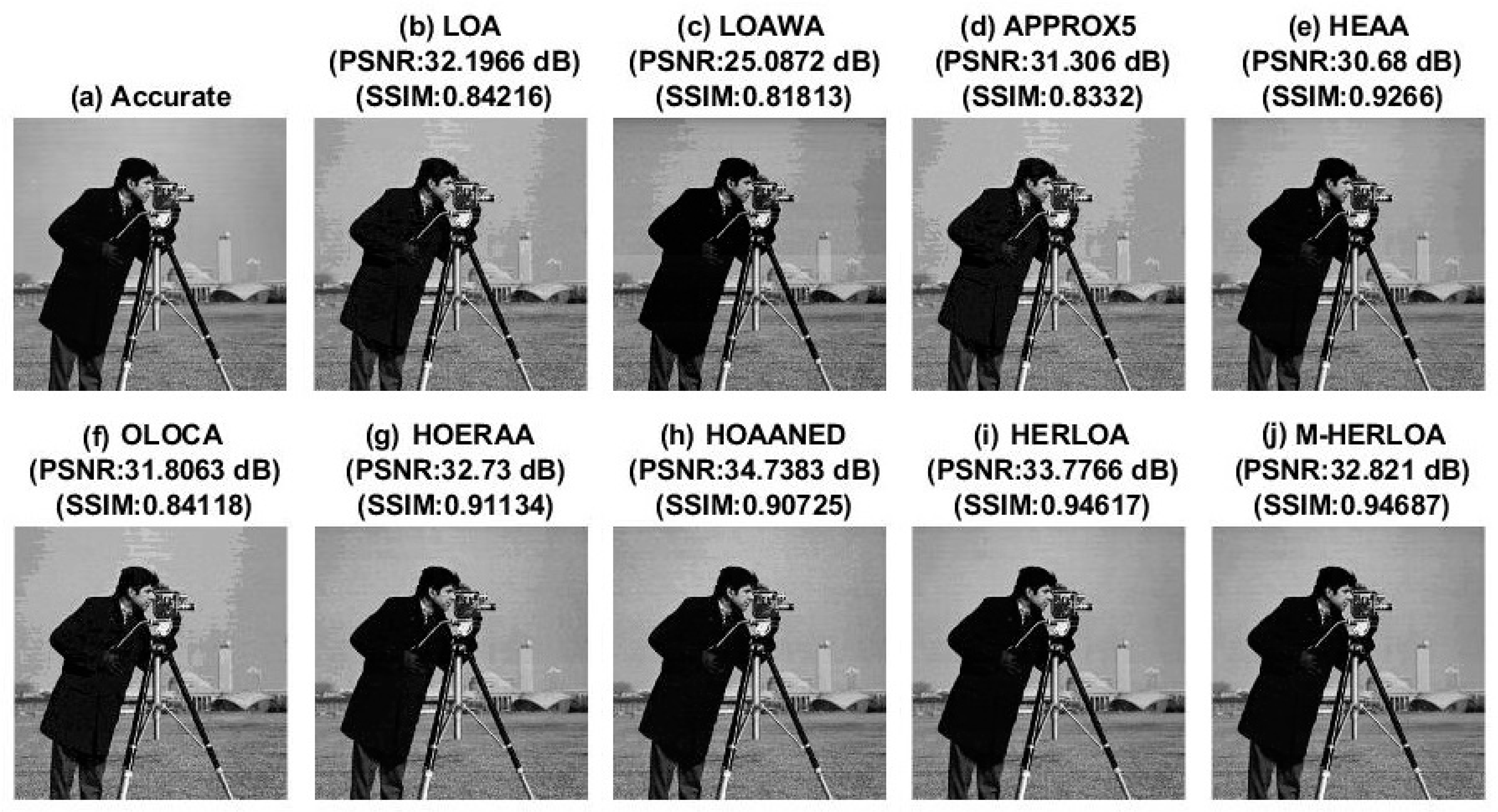
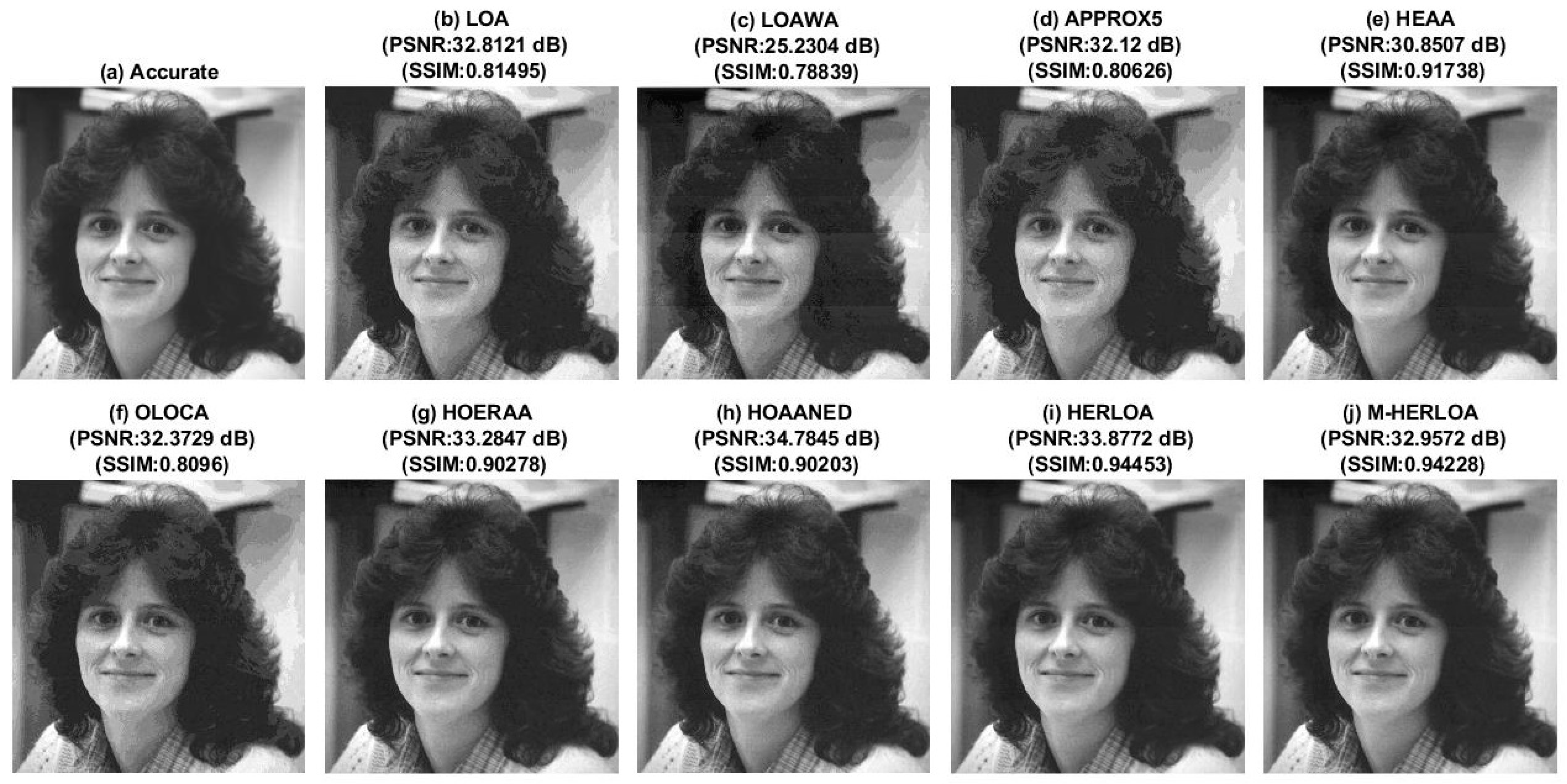
In general, the savings in design metrics achieved by an SAA compared to the accurate adder are proportionate to the degree of incorporated approximation [21,22]. Therefore, an optimum approximation has to be determined to strike an acceptable compromise between maximizing the savings in design metrics and ensuring the good quality of results (here, the quality of DIP results). Based on an extensive trial-and-error, a 32-bit approximate adder comprising a 10-bit inexact part was found to be acceptable for the DIP application [22], and this was adopted for this work. The images reconstructed using different approximate adders such as LOA [19], LOAWA [29], APPROX5 [30], HEAA, OLOCA [31], HOERAA, HOAANED, HERLOA [32], and M-HERLOA were compared with the original image on the basis of two well-known figures of merit, namely the peak signal to noise ratio (PSNR) [33] and the structural similarity index metric (SSIM) [34]. PSNR (in dB) varies from zero to infinity, and SSIM varies from 0 to 1 decimal. A higher PSNR indicates low noise or distortion, and a higher SSIM indicates greater structural similarity between the reference (original) image and the target image. The image reconstructed using the accurate adder had a PSNR of infinity and SSIM of 1 since no noise was introduced in the accurate computation of FFT and IFFT, and the original image was faithfully reconstructed. On the contrary, the images reconstructed using approximate adders did not have ideal PSNR and SSIM values since noise was introduced during the approximate computation of FFT and IFFT. Figure 2, Figure 3 and Figure 4 show example DIP results obtained for ‘lena’, ‘cameraman’, and ‘woman with dark hair’ images.
Figure 2a, Figure 3a and Figure 4a show the images reconstructed using the accurate adder, and Figure 2b–j, Figure 3b–j and Figure 4b–j show the images reconstructed using different approximate adders. The PSNR and SSIM values of images reconstructed using different approximate adders are given above the respective images for a quick comparison. In Figure 2, Figure 3 and Figure 4, it can be noticed that among the approximate adders, HOAANED achieved greater PSNR, and HERLOA and M-HERLOA achieved relatively greater SSIM.
2.3. Error Calculation for Approximate Adders
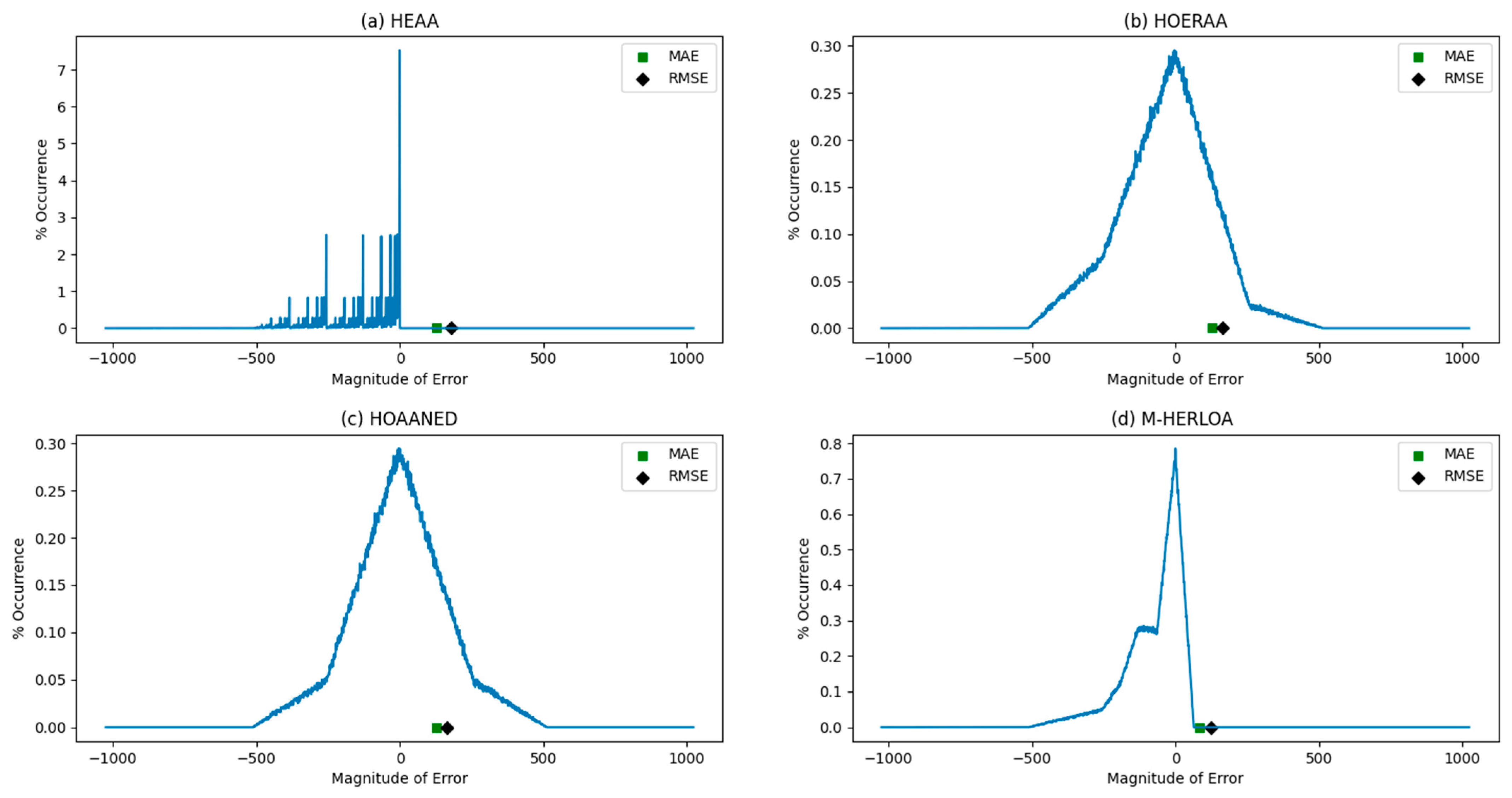
As mentioned previously, 32-bit approximate adders with a 10-bit inexact part were found to be acceptable for the DIP application [22]. Hence, we performed error analyses of approximate adders by considering the same sizes. We generated one million random vectors for the adder inputs and supplied them to the accurate and approximate adders to perform error analysis. To calculate the error, the sum produced by each approximate adder was compared with the sum produced by the accurate adder for every input applied. Two popular error metrics used in approximate computing, namely mean absolute error () and root mean square error () were calculated for the approximate adders, and they are given by Equations (1) and (2), respectively. RMSE better characterizes the extent of signal degradation in a digital signal processing application [35]. In Equations (1) and (2), represents the number of random input vectors, which is equal to 1 million. The adder inputs are represented by and , signifies the sum output by the accurate adder, and denotes the sum output by an approximate adder.
The MAE and RMSE calculated for the approximate adders are given in Table 1, which shows that M-HERLOA presented lesser MAE and RMSE compared to its counterparts. With respect to the random inputs applied, the respective error magnitudes of our proposed approximate adders, namely HEAA, HOERAA, HOAANED, and M-HERLOA, were captured in the form of an error characteristic plot, which is shown in Figure 5. In Figure 5, the error magnitudes are plotted along the X-axis, and the corresponding percentage of the error occurrence is plotted along the Y-axis. The plot legends shown in Figure 5, i.e., the green square and the black diamond, indicate the positions of MAE and RMSE, respectively, in the error characteristic plot. It can be observed that among our approximate adders, HOAANED presented an almost a symmetric and near-normal error distribution.
2.4. Design Metrics of Accurate and Approximate Adders
For an FPGA-based implementation, Approximator was used to automatically generate behavioral descriptions of our approximate adders HEAA, HOERAA, HOAANED, and M-HERLOA in Verilog HDL. The accurate adder and other approximate adders, i.e., LOA, LOAWA, APPROX5, OLOCA, and HOERAA, were manually described behaviorally in Verilog HDL. The addition operator was used to describe the accurate adder and the exact parts of approximate adders. This paved the way for the utilization of fast carry logic inherent in an FPGA slice to realize addition in a high-speed fashion upon synthesis. The accurate and approximate adders were synthesized and implemented on a Xilinx Artix-7 FPGA (device: xc7a100tcsg324-3) using Vivado 2018.3 design tool. In the accurate adder code and the approximate adder codes meant for FPGA-based implementation, a pair of registers was provisioned before the adder inputs to avoid unnecessary input–output (IO) routing delay from dominating the clock period, following a standard FPGA design practice. A register was present following the adder outputs. Thus, the adder was sandwiched between a set of input and output registers, which were driven by the same clock. For synthesis, the Flow_AreaOptimized_high strategy was used, and for implementation, the default strategy was used. Table 2 presents the FPGA design parameters such as minimum clock period, number of look-up tables (LUTs) and flip-flops (FFs), and total on-chip power consumption of accurate and approximate adders, which were estimated after place and route.
Table 2 generally shows that the approximate adders were found to have reduced clock periods, utilize fewer resources, and consume less power than the accurate FPGA adder. Since the exact part of the approximate adders was only 22 bits compared to the accurate adder, which comprised 32 bits, the critical path delay was less for the former; this led to reductions in their minimum clock periods. The inexact part of the approximate adders had reduced logic, and this led to reductions in the number of LUTs and/or FFs required for implementing the approximate adders compared to the accurate adder. Consequently, the approximate adders were found to consume less on-chip power compared to the accurate FPGA adder.
With respect to LOA, LOAWA, HEAA, and HERLOA, the logic of their inexact part was less compared to the accurate FPGA adder logic, which led to savings in the number of LUTs required for their implementation. However, the number of FFs required for the inputs and outputs of LOA, LOAWA, HEAA, and HERLOA was the same as the accurate FPGA adder. In the case of APPROX5, to are forwarded as sum bits to , respectively, and therefore no LUTs were required for realizing to . This is the reason why APPROX5 required only 22 LUTs compared to the accurate FPGA adder, which required 32 LUTs. In APPROX5, was given as the carry input to the exact part and to were discarded, thus saving 9 FFs in total compared to the accurate FPGA adder. In the case of OLOCA, the inexact part logic was reduced compared to the accurate FPGA adder logic, and this led to a savings in the number of LUTs required for its implementation. to were assigned a constant 1 in OLOCA, and thus no FFs were required for to , to , and to which resulted in a total savings of 24 FFs for OLOCA compared to the accurate FPGA adder. With respect to HOERAA and HOAANED, in their inexact parts, excepting and , the rest of the sum bits to were tied to a constant 1, as seen in Figure 1c,d. Given that the inexact part comprised 10 bits for the considered DIP application, 16 input bits, i.e., to and to , were discarded and to were assigned a constant 1—these led to a reduction of 24 FFs for HOERAA and HOAANED compared to the accurate FPGA adder. In the case of M-HERLOA, to were assigned a constant 1 and to and to were discarded—these led to the saving of 18 FFs for M-HERLOA compared to the accurate FPGA adder.
In Section 2.2, HOAANED was found to enable greater PSNR, and HERLOA and M-HERLOA were found to enable greater SSIM for the considered DIP application. Nevertheless, M-HERLOA was found to be more optimized in logic compared to HERLOA (as seen from Table 2) while having relatively reduced error metrics (as seen from Table 1). Hence, M-HERLOA is preferable to HERLOA. Given these data, it can be noted in Table 2 that HOAANED achieved a 11% reduction in clock period, required 28% fewer LUTs and 25% fewer FFs, and consumed 10% less on-chip power compared to the accurate FPGA adder. On the other hand, M-HERLOA achieved a 9.5% reduction in clock period, required 22% fewer LUTs and 19% fewer FFs, and consumed 9% less on-chip power compared to the accurate FPGA adder.
For an ASIC-type standard cell-based implementation, Approximator was used to automatically generate structural, i.e., gate-level descriptions, of our approximate adders HEAA, HOERAA, HOAANED, and M-HERLOA while the accurate adder and other approximate adders (i.e., LOA, LOAWA, APPROX5, OLOCA, and HERLOA) were manually coded in Verilog HDL at the gate-level. The accurate adder and the exact parts of approximate adders were described using the high-speed CLA architecture presented in [36]. For an ASIC-type implementation, Approximator, by default, utilizes the CLA architecture of [36] to describe the exact parts of approximate adders. The accurate 32-bit adder required eight 4-bit CLAs, and the exact part of the approximate adders required five 4-bit CLAs and one 2-bit CLA. The accurate and approximate adders were synthesized by Synopsys Design Compiler using a 32/28 nm CMOS standard cell library [37] with speed set as the optimization goal. A typical case process, with a supply voltage of 1.05 V and an operating temperature of 25 °C, was considered. The functional simulation of accurate and approximate adders was performed using Synopsys VCS by supplying a test bench that comprised about a thousand random input vectors at a time period of 2 ns (500 MHz). Synopsys PrimeTime and PrimePower were used to estimate critical path delay and total power dissipation. The total area of the adder implementations included cell area and interconnect area, which was estimated using Design Compiler. Wire loads were included by default and a fanout-of-4 drive strength was assigned to all the sum bits. The ASIC-based design metrics of accurate and approximate adders are given in Table 3. Table 3 reflects a similar trend as Table 2 with the approximate adders reporting reduced delay, area, and power compared to the accurate adder (here, CLA).
The accurate CLA was 32 bits in size, whereas the exact part of the approximate adders was only 22 bits in size. Hence, the critical path delay of the latter was expected to be less than the former, which is substantiated by the results given in Table 3. Since the approximate adders had an exact part and an inexact part and because the inexact part had reduced logic compared to the accurate CLA, the approximate adders occupied less area than the accurate adder, as seen from Table 3. The reduced area of approximate adders compared to the accurate adder resulted in reduced power, as noticed from Table 3. With respect to an ASIC-type implementation, HOAANED presented a 18% reduction in critical path delay, 25% less area, and 28% less power than the accurate CLA, while M-HERLOA presented an 18% reduction in critical path delay, 23% less area, and 27% less power than the accurate CLA.
3. Approximate Multipliers
In this section, how approximate array multipliers (AAMs) are derived from an accurate array multiplier is firstly described by considering an example 8 × 8 multiplication. Secondly, the error metrics (MAE and RMSE) of different 8 × 8 AAMs are given. Thirdly, the usefulness of 8 × 8 AAMs for a digital image blending (DIB) application is discussed, and lastly, the design metrics of a directly synthesized high-speed accurate multiplier, an accurate array multiplier, and AAMs corresponding to the DIB application are provided.
3.1. Approximate Array Multipliers—Architectures
The architecture of an accurate 8 × 8 array multiplier is shown in Figure 6, where A7–A0 and B7–B0 represent the multiplier inputs and P15 to P0 denote the product bits. Bits A7, B7, and P15 are most significant, while bits A0, B0, and P0 are least significant. As shown in Figure 6, 2-input AND gates were used to realize the partial products ranging from A0B0 to A7B7, and there was a total of 64 partial products. A carry save adder was embedded within the accurate array multiplier, which consisted of 8 half adders and 48 full adders.
AAMs can be obtained by introducing vertical and/or horizontal cuts to an accurate array multiplier [19]. It was shown in [24] that vertical cuts are preferable over horizontal cuts since the former gradually eliminates partial products starting from the least significant ones, whereas the latter tends to eliminate some significant partial products straightaway. Hence, AAMs are better derived by making vertical cuts in an accurate array multiplier. Figure 6 shows examples of vertical cuts labelled as V0 to V10, which are shown in red dashed lines, any of which can be introduced into an accurate array multiplier to derive an AAM.
Figure 7 illustrates the impact of a vertical cut V8 on the accurate array multiplier. After introducing a vertical cut, the logic to the right side of the cut was eliminated, as shown in light grey. As a result, product bits P8 to P0 were left dangling, which may have been assigned binary 0 or 1. The five full adders highlighted in blue to the left side of V8 had some of their inputs cut, as shown in pink—these are called dangling internal inputs and could be assigned binary 0 or 1. Based on a diverse assignment of binary values, four AAM architectures were derived, namely AAM00 [38], AAM01 [25], AAM10 [25], and AAM11 [25], and are described below.
- AAM00—Binary 0 is assigned to dangling internal inputs and dangling product bits.
- AAM01—Binary 0 is assigned to dangling internal inputs and binary 1 is assigned to dangling product bits.
- AAM10—Binary 1 is assigned to dangling internal inputs and binary 0 is assigned to dangling product bits.
- AAM11—Binary 1 is assigned to dangling internal inputs and dangling product bits.
In Figure 7, the full adder shown in green dotted lines that produced product bit P9 earlier had two of its inputs cut, so it was eliminated, thus resulting in the full adder present above it producing P9. Additionally, the full adder that produced product bit P10 earlier had one of its inputs cut, so it was reduced to a half adder, as highlighted in orange in Figure 7.
When the full adders highlighted in blue in Figure 7 were assigned binary 0, with respect to the AAM00 and AAM01 architectures, they were reduced to half adders as shown in Figure 8. On the other hand, if those full adders were assigned binary 1 with respect to the AAM10 and AAM11 architectures, they were reduced to a combination of a 2-input XNOR gate and a 2-input OR gate (as shown in Figure 9), with the former producing an approximate sum output and the latter producing an approximate carry output.
3.2. Error Analysis of Approximate Multipliers
For an image blending application that is discussed later, an 8 × 8 multiplier was deemed sufficient and hence was considered here. An 8 × 8 multiplier has a total of distinct inputs, and all the inputs were considered to accurately calculate the MAE and RMSE of different AAMs. Equations (3) and (4) were used to calculate MAE and RMSE of AAMs, respectively. In Equations (3) and (4), i and j denote the multiplicand and multiplier, respectively; represents the product produced by the accurate array multiplier; and represents the product produced by an AAM.
Table 4 shows the MAE and RMSE of different AAMs. The suffix ‘-V8′ is associated with the AAM00-V8, AAM01-V8, AAM10-V8, and AAM11-V8 AAMs to convey that the different AAMs were derived through a vertical cut V8 made on the accurate array multiplier. In [25], it was shown that the V8 cut is an acceptable approximation for the DIB application, so we considered the same here to provide an illustration. In Table 4, it can be seen that the AAM01 architecture had reduced MAE and RMSE compared to the other AAM architectures. It was shown in [24] that AAM01 consistently enabled reduced MAE and RMSE compared to the other AAM architectures for vertical cuts starting from V1. Hence, on the basis of error metrics, AAM01 is preferable to its counterparts.
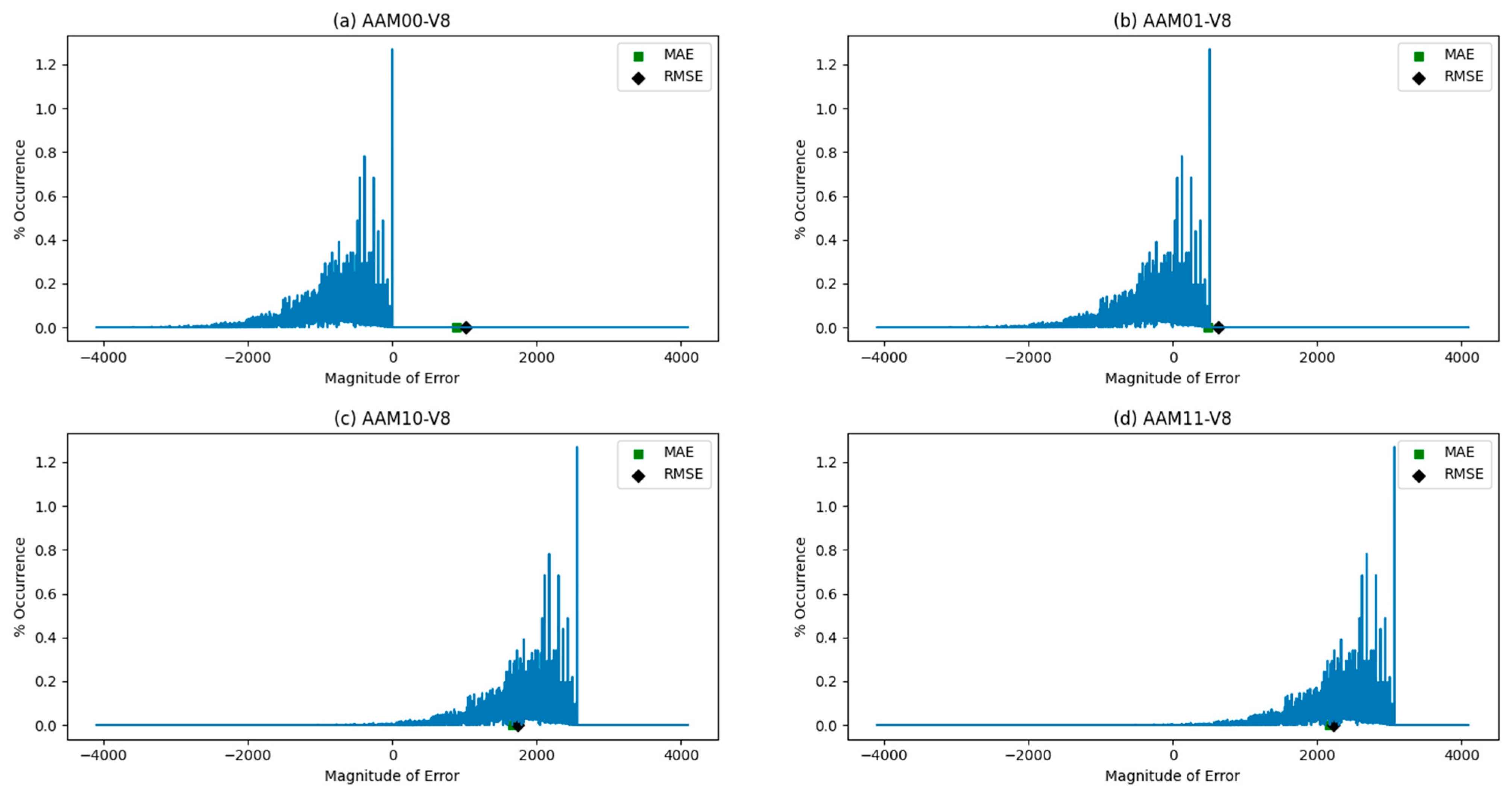
Figure 10 shows the error characteristic plots of AAMs, with error magnitudes plotted along the X-axis and their frequency of occurrence in percentage plotted along the Y-axis. The positions of MAE and RMSE on the error characteristic plots are also shown and highlighted by the green square and the black diamond, respectively. In Figure 10, it can be seen that AAM00-V8 had negative error magnitudes, while AAM10-V8 and AAM11-V8 had positive error magnitudes. The error magnitudes of AAM11-V8 were, however, greater than AAM10-V8 due to over-approximation. AAM01-V8 had negative and positive error magnitudes, although the errors appeared relatively more on the negative side than the positive side. Nevertheless, this helps to balance the overall error for AAM01-V8, which is beneficial and does not feature in other AAM architectures. We observed the same phenomenon in multiple error analyses, performed by considering different vertical cuts on the accurate array multiplier. AAM01-V8 presented reduced MAE and RMSE compared to its counterparts, so, in general, it is preferable.
3.3. Image Blending Application
To evaluate the performance of different AAMs, we considered a DIB application. To perform blending, two digital images with a grayscale resolution of 8 bits and a spatial resolution of 512 × 512 pixels were considered. An 8 × 8 multiplier is sufficient to perform DIB, which involves the pixel-wise multiplication of the two images to obtain a blended image with the same spatial resolution and a grayscale resolution of 16 bits. To perform 8 × 8 multiplication, we used an 8 × 8 accurate array multiplier and different 8 × 8 AAMs discussed in the previous sub-section. For the DIB application, the vertical cut V8 was found to be an optimum approximation [25]. To measure the quality of image blending, PSNR and SSIM were used, as discussed in Section 2.2.
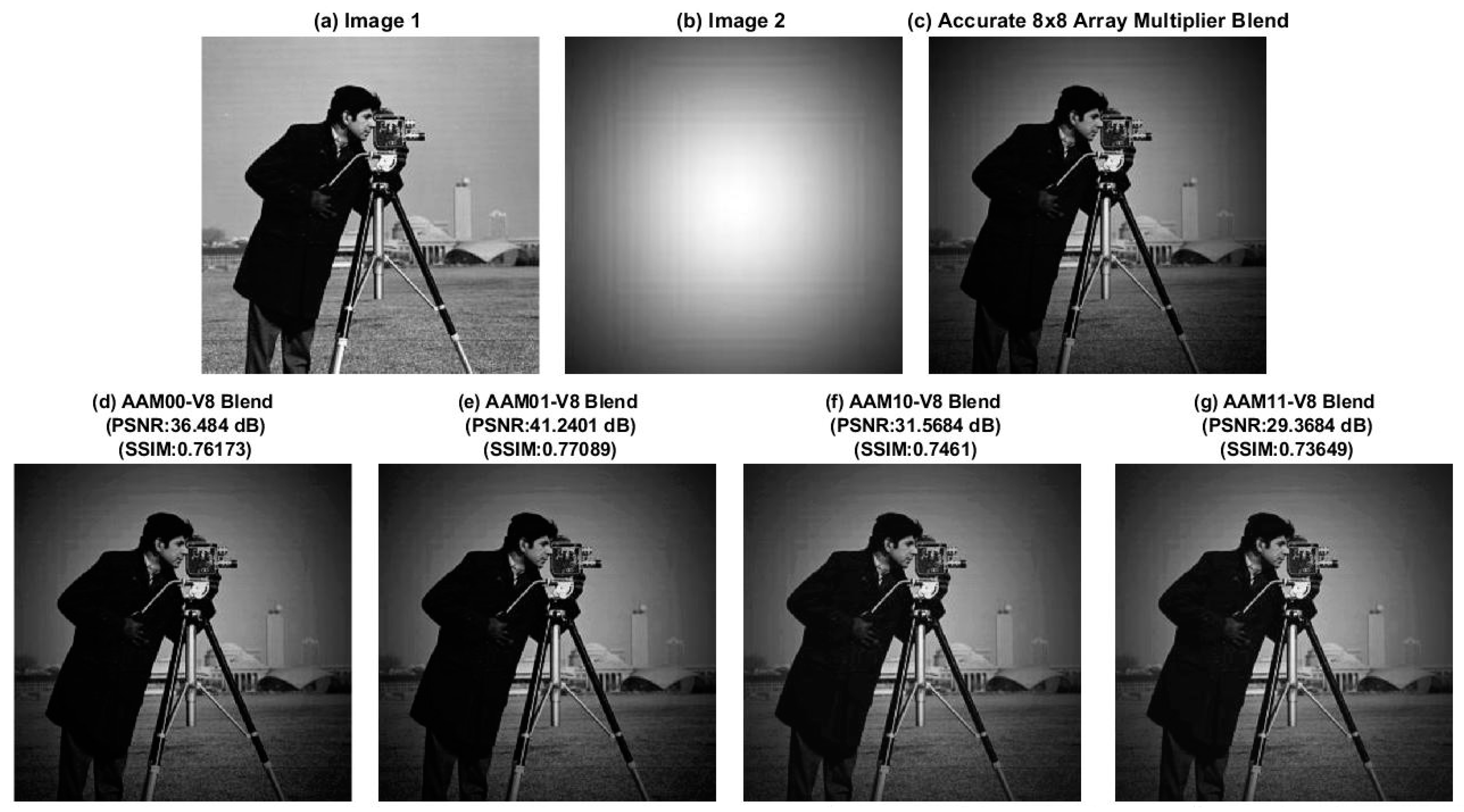
We considered blending of ‘lena’, ‘cameraman’, and ‘woman with dark hair’ images individually with a ‘mask’ image, and the results of image blending based on accurate and approximate multiplications are shown in Figure 11, Figure 12 and Figure 13, respectively. Figure 11c, Figure 12c and Figure 13c show the accurately blended images. Figure 11d, Figure 12d and Figure 13d show the images blended using AAM00-V8; Figure 11e, Figure 12e and Figure 13e show the images blended using AAM01-V8; Figure 11f, Figure 12f and Figure 13f show the images blended using AAM10-V8; and Figure 11g, Figure 12g and Figure 13g show the images blended using AAM11-V8. In Figure 11, Figure 12 and Figure 13, it can be observed that the AAM01 architecture (here, in particular AAM01-V8) consistently enabled greater PSNR and SSIM for the blended images compared to the blended images obtained using other AAMs such as AAM00-V8, AAM10-V8, and AAM11-V8. Hence, the blending of images using the AAM01 architecture (here AAM01-V8) is preferable. The reason for this could be the reduced MAE and RMSE of AAM01-V8, as seen in Table 4, as well as some balancing in the error distribution achieved by AAM01-V8, as observed in Figure 10.
3.4. Design Metrics of Accurate and Approximate Multipliers
An accurate multiplier can be efficiently implemented using a DSP core for an FPGA-based implementation, so the approximate implementation of multipliers using LUTs was not considered. Rather, we considered an ASIC-type standard cell-based implementation of accurate and approximate multipliers. An accurate 8 × 8 array multiplier and approximate 8 × 8 array multipliers corresponding to vertical cut V8 were structurally described in Verilog HDL. Nevertheless, the Verilog HDL code of AAM01-V8 was automatically generated by Approximator. Additionally, an accurate 8 × 8 multiplier was behaviorally described in Verilog HDL using the multiplication operator. The multipliers were synthesized by Design Compiler for high-speed using a standard digital cell library [37], and their total area including cells area and interconnect area was estimated. FO-4 drive strength was applied on all the product bits, and the default wire load model was used. The same library specification mentioned in Section 2.4 was adopted for simulation and synthesis. To perform functional simulations using VCS, a test bench comprising about 1000 random input vectors was supplied to the multipliers at a time period of 2.5 ns (400 MHz). Subsequently, the switching activity information was obtained and used to estimate the total power dissipation using PrimePower. The critical path delay of the synthesized multipliers was estimated using PrimeTime. The design metrics of the multipliers are given in Table 5.
The accurate multiplier, behaviorally described using the multiplication operator in Verilog HDL, was automatically synthesized for high-speed using Design Compiler, and its design metrics were found to be better optimized compared to the structurally described accurate array multiplier synthesized using Design Compiler, as seen from Table 5. In Figure 6, it can be observed that the critical path of the accurate array multiplier schematic consisted of a 2-input AND gate (that realizes a partial product), two half adders, and twelve full adders. On the other hand, the critical paths of AAM00-V8 and AAM01-V8 comprised one 2-input AND gate, two half adders, and eight full adders, as seen in Figure 8. Except for the constant binary assignment to the dangling product bits, the logic of AAM00 and AAM01 architectures is the same, so their critical paths are the same. Based on the same explanation, the critical paths of AAM10 and AAM11 architectures are also the same. The critical paths of AAM10-V8 and AAM11-V8 comprised one 2-input AND gate, one 2-input OR gate, one half adder, and eight full adders. Since the number of gates traversed in the critical path of AAMs was less than the number of gates traversed in the critical path of the accurate array multiplier, they had a reduced critical path delay compared to the accurate multiplier described using the multiplication operator and the structurally described accurate array multiplier, as noted in Table 5.
The difference between AAM00-V8 and AAM01-V8 was that in the former, product bits P8 to P0 were assigned a constant 0 by tying them to ground using tie-to-low (TIEL) standard cells, and in the latter P8 to P0 were assigned a constant 1 by tying them to supply using tie-to-high (TIEH) standard cells. The characteristics of TIEL and TIEH standard cells in the library [37] are the same, so AAM00-V8 and AAM01-V8 had the same area and power, as mentioned in Table 5. The same explanation fits the combination of AAM10-V8 and AAM11-V8, which also had the same area and power.
AAM10-V8 and AAM11-V8 were slightly better optimized in terms of the design metrics compared to AAM00-V8 and AAM01-V8, but in Section 3.2 and Section 3.3, it was noted that the AAM01 architecture was preferable to its counterparts. Accordingly, from Table 5, AAM01-V8 was found to achieve a 9.7% reduction in critical path delay, a 60.6% reduction in area, a 64.7% reduction in power compared to the directly synthesized high-speed accurate multiplier, as well as a 21% reduction in critical path delay, a 63.3% reduction in area, and a 72.3% reduction in power compared to the accurate array multiplier.
4. Automated Generation of Approximate Arithmetic Circuits
In this section, we describe the software tool Approximator, developed to automatically generate HDL codes of approximate adder and multiplier architectures discussed in the previous section, which may be of any size. This tool eliminates the need for a manual coding of approximate arithmetic circuits, which would become cumbersome even for a medium-size specification, especially when the approximation may have to be varied depending on the target application. Approximator is able to perform error analysis depending on user-specified inputs or on the basis of randomly generated inputs. Approximator is also able to provide information about the accuracy of results produced by approximate adders and multipliers. Approximator is made available in a GUI form that is simple, interactive, and convenient to use, so a user does not have to bother with the internal details. Moreover, the source code of Approximator has been made open for access on GitHub [26], which will allow for the further development or modification of the tool to suit a user’s requirement, thus paving the way for future advancement. The GUI version of Approximator was developed following the SOLID principles of object-oriented programming [39].
Approximator is able to generate FPGA-based and ASIC-based Verilog HDL codes of approximate adders such as HEAA, HOERAA, HOAANED, and M-HERLOA of any size with an exact part and an inexact part, according to a user’s specification. In the FPGA-based codes, the adder remains sandwiched between a pair of input and output registers that are driven by a common clock, and two sets of input registers are provisioned prior to the adder logic to eliminate unnecessary IO routing delay from dominating the critical path delay; this is in line with a standard FPGA-based design practice. In ASIC-based codes, the approximate adder logic is alone generated, as this may subsequently be used as a part of a sub-system or a system, so the clock can be separately determined. Approximator is also able to generate ASIC-based Verilog HDL codes of the approximate array multiplier AAM01 of any size for any specified (and permissible) vertical cut. The size of AAM01 could be any M × N, where M may or may not be equal to N. Additionally, the tool can be used to perform error and accuracy analyses of approximate adders and approximate multipliers. The features of Approximator are given in Table 6.
The GUI version of Approximator is wrapped on top of a command line tool (CMD tool) that was developed during the initial stage. Both GUI and CMD versions of Approximator were developed and tested in Python version 3.7.3 using multiple open-source projects. ‘Pyverilog’ [40] was combined with ‘Veriloggen’ [40] for the automatic generation of Verilog HDL code, NumPy [41] was used for array evaluations in error and accuracy analysis, and PySimpleGUI [42] was used to create a base GUI framework. The full list of dependencies is given in Table 7.
4.1. GUI Version of Approximator
Figure 14 shows a flowchart that visually describes the steps to be followed by a user while using the GUI version of Approximator. The user should install the packages listed in Table 7 to be able to use the GUI version of Approximator. After installing the packages, the user should run the ‘GUIMainToolCode.py’ Python file. A window titled ‘Approximate Computing Tool’, as shown in Figure 15, then appears. The window has three tabs, and a user can select the appropriate tab (‘Verilog Code Generator’, ‘Error Analysis’, or ‘Accuracy Analysis’) depending upon the requirement. For an illustration, important sections of the ‘Verilog Code Generator’ tab are labeled in red from 1 to 6. Label 1 uses radio buttons to allow the user to select the Type of Verilog code. Label 2 allows the user to select the number of adder bits for ASIC-based adder and FPGA-based adder. In the case of the ASIC-based Multiplier, Label 2 takes in two inputs, namely the number of multiplicand bits and the number of multiplier bits. Label 3 uses a slider to determine the number of bits for the accurate and inaccurate parts of the approximate adder. For the approximate multiplier, Label 3 uses a text box for the user to specify the position of the vertical cut (V-cut). Label 4 allows the user to select the required approximate adder or multiplier architecture. Label 5 shows how a user can specify a path for storing the Verilog file that will be generated corresponding to the specified approximate arithmetic circuit. The user can choose to generate either a Verilog code or exit from the GUI—this is indicated by Label 6. The GUI tool ensures that the user inputs are within permissible limits. An error message, as shown in Figure 16, is invoked if a user input does not satisfy the input constraints, as shown in Table 8, Table 9 and Table 10 for Verilog code generation, error analysis, and accuracy analysis, respectively.
4.2. Developer Perception of Approximator GUI
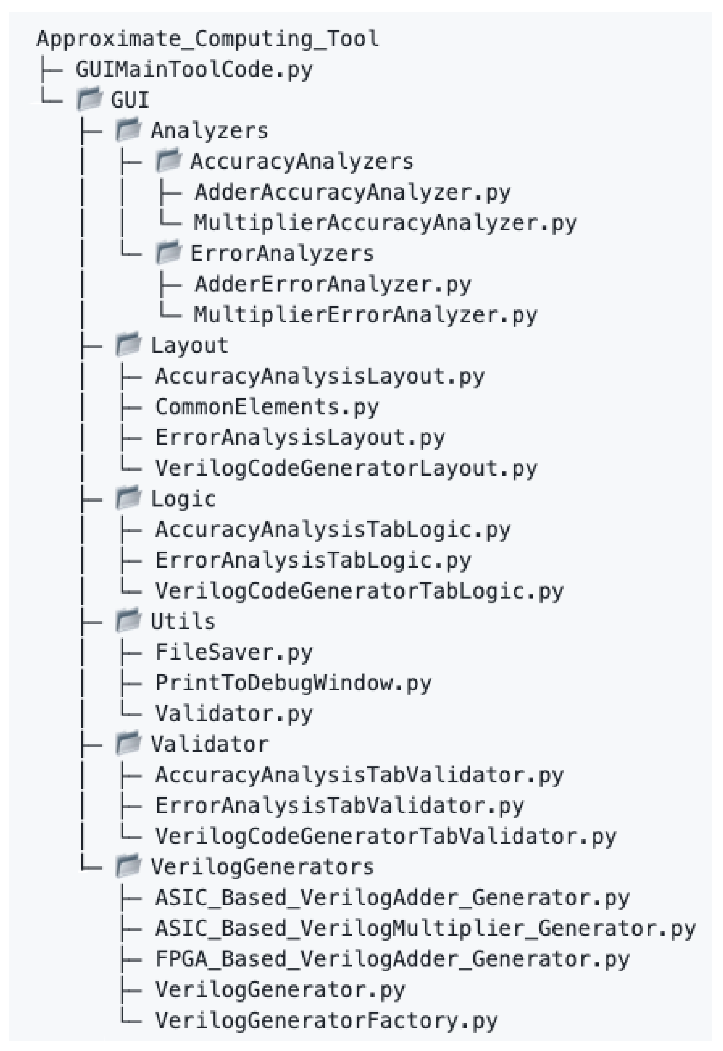
The modular structure of the GUI version of Approximator allows for the logical breakdown of modules, which facilitates the inclusion of any new functionalities into the tool by a future developer. Figure 17 portrays the tree layout of files used in the GUI. A user may run the ‘GUIMainToolCode.py’ file, which uses files in the ‘GUI.Layout’ module to define the layout, placement, and style of the GUI elements such as text boxes, radio buttons, slider, tabs, windows, and drop-down lists. Once the layout is defined, the ‘GUIMainToolCode.py’ runs an appropriate file inside the ‘GUI.Logic’ module depending on the application tab selected by the user. A suitable function in ‘VerilogCodeGeneratorTabLogic.py’, ‘ErrorAnalysisTabLogic.py’, or ‘AccuracyAnalysisTabLogic.py’ is then called depending on whether the user selects the ‘Verilog Code Generator’ (default selection), ’Error Analysis’, or ‘Accuracy Analysis’ tab in the GUI window.
The files inside the ‘GUI.Logic’ module consider the user inputs, make the appropriate functionality of the tool visible to the user based on the specified inputs, and forward the inputs to the ‘GUI.Validator’ module. Based on the application tab selected by the user, the relevant functions in the ‘VerilogCodeGeneratorTabValidator.py’, ‘ErrorAnalysisTabValidator.py’, and ‘AccuracyAnalysisTabValidator.py’ files in the ‘GUI.Validator’ module verify whether the respective constraints given in Table 8, Table 9 and Table 10 are satisfied. The information regarding the same is returned to the appropriate function in the ‘GUI.Logic’ module. If the input constraints are not satisfied, an error prompt is raised; an example is shown in Figure 16. If the input constraints are satisfied, the application requested by the user is executed, which is explained in the forthcoming subsections.
4.2.1. Verilog Code Generation for Approximate Arithmetic Circuits
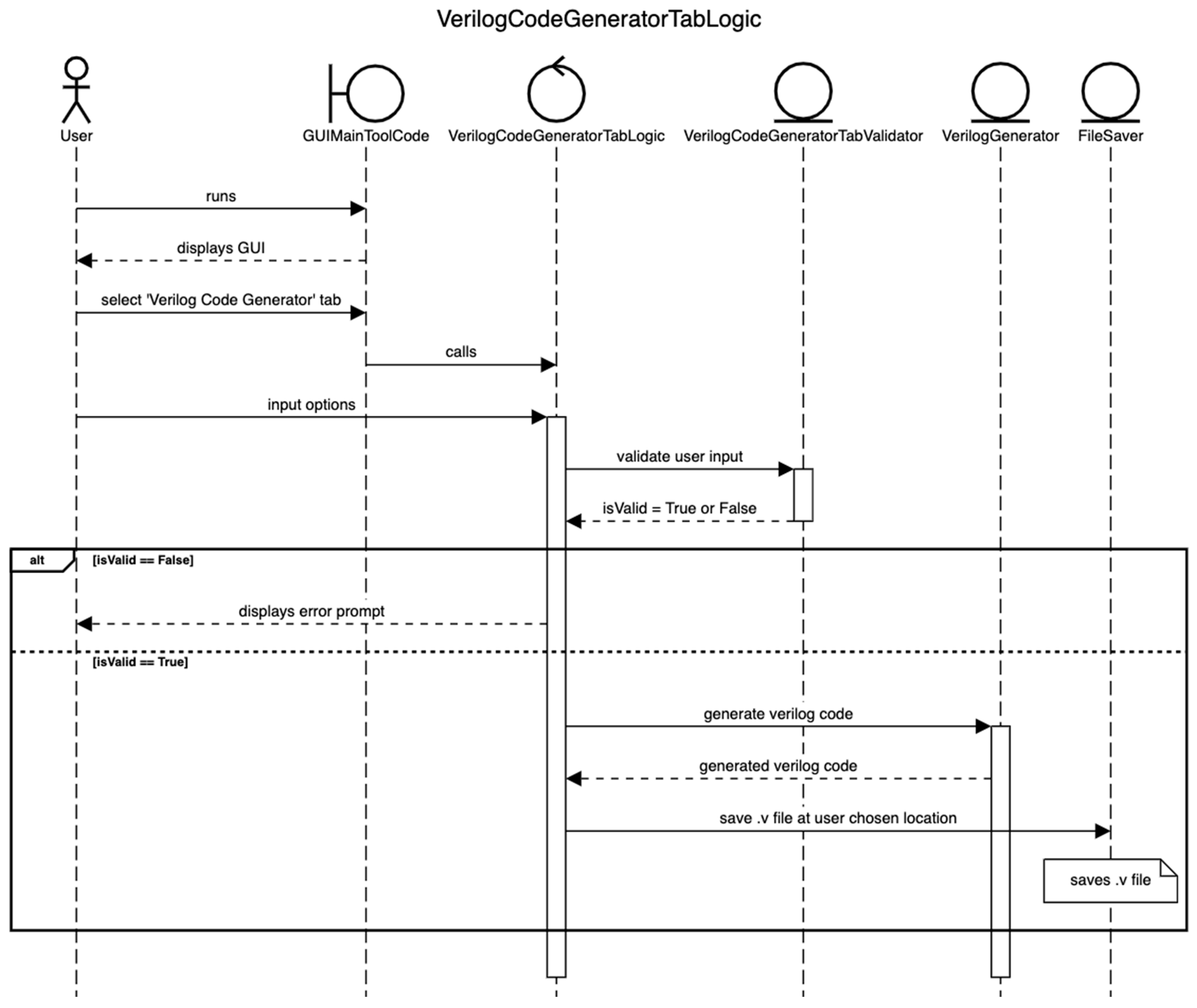
The ’VerilogCodeGeneratorTabLogic.py’ in the ‘GUI.Logic’ module calls the appropriate method in the ‘VerilogGenerator.py’ file present in the ’GUI.VerilogGenerators’ module. This method passes information regarding the type of Verilog code (FPGA-based Adder, ASIC-based Adder, or ASIC-based Multiplier) required by the user to a method in the ‘VerilogGeneratorFactory.py’. Based on this information, either ‘FPGA_Based_VerilogAdder_Generator.py’, ‘ASIC_Based_VerilogAdder_Generator.py’, or ‘ASIC_Based_VerilogMultiplier_Generator.py’ is run, which use the Pyverilog and Veriloggen packages to generate the Verilog code for FPGA-based adder, ASIC-based adder, or ASIC-based multiplier, respectively. The generated Verilog file adheres to the user specifications such as the type of specified approximate adder or multiplier architecture, i.e., whether HEAA, HOERAA, HOAANED, M-HERLOA, or AAM01 with V-cut, number of input bits for the adder or multiplier, and the extent of approximation desired. The generated Verilog file is saved in the path specified by the user. The ‘FileSaver.py’ in the ‘GUI.Utils’ module is used for naming the saved Verilog file. Figure 18 shows a sequence diagram to visualize describe the steps followed for Verilog code generation.
4.2.2. Error Analysis of Approximate Arithmetic Circuits
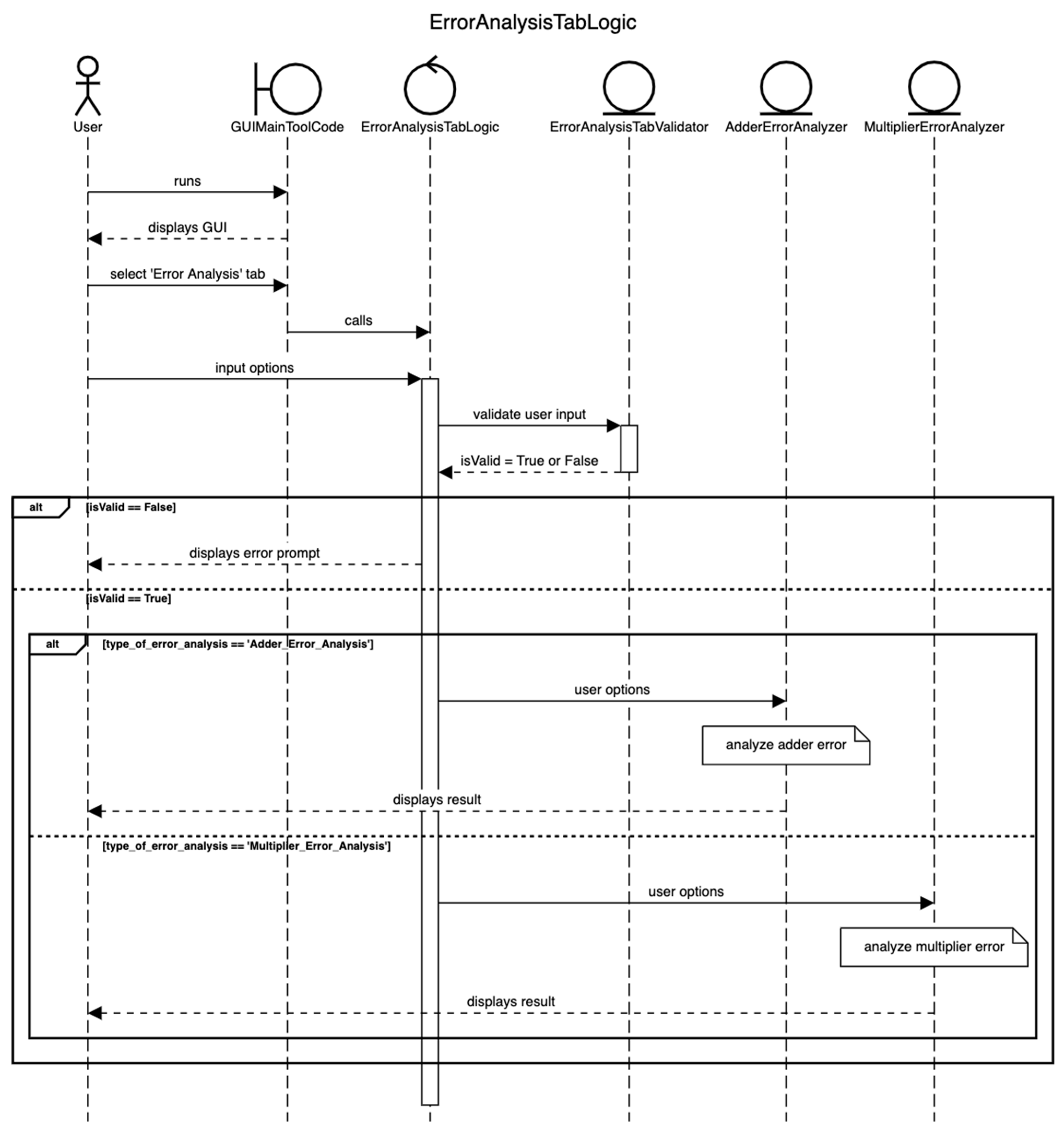
Figure 19 shows the sequence diagram for error analysis. ’ErrorAnalysisTabLogic.py’ in the ‘GUI.Logic’ module uses the ‘AdderErrorAnalyzer.py’ and ‘MultiplierErrorAnalyzer.py’ files in the ‘GUI.Analyzers.ErrorAnalyzers’ module to perform error analysis for approximate adders and approximate multipliers, respectively. These analyzers use suitable functions in ‘ApproxAdders.py’ and ‘ApproxMultipliers.py’ to calculate sum and product corresponding to approximate adders and multipliers, respectively.
If the size of the approximate adder is less than or equal to 10 bits and the size of the approximate multiplier is less than or equal to 10 bits × 10 bits, the error parameters are accurately calculated; otherwise, the error parameters are approximately calculated by supplying a million random input vectors internally generated. The generalized equation to estimate the average error (AE) of an approximate adder is given by Equation (5). The generalized equations to calculate MAE and RMSE of approximate adders are given by Equations (1) and (2) in Section 2.3. The generalized equations to calculate AE, MAE, and RMSE of approximate multipliers are given by Equations (6)–(8), respectively. In Equations (1)–(3) and (5)–(8), L represents the number of random input vectors supplied to calculate the error parameters, and we considered L as 1 million. In Equations (1), (2), and (5), and represent the augend and addend inputs with respect to addition, and in Equations (6)–(8), and represent the multiplicand and the multiplier with respect to multiplication.
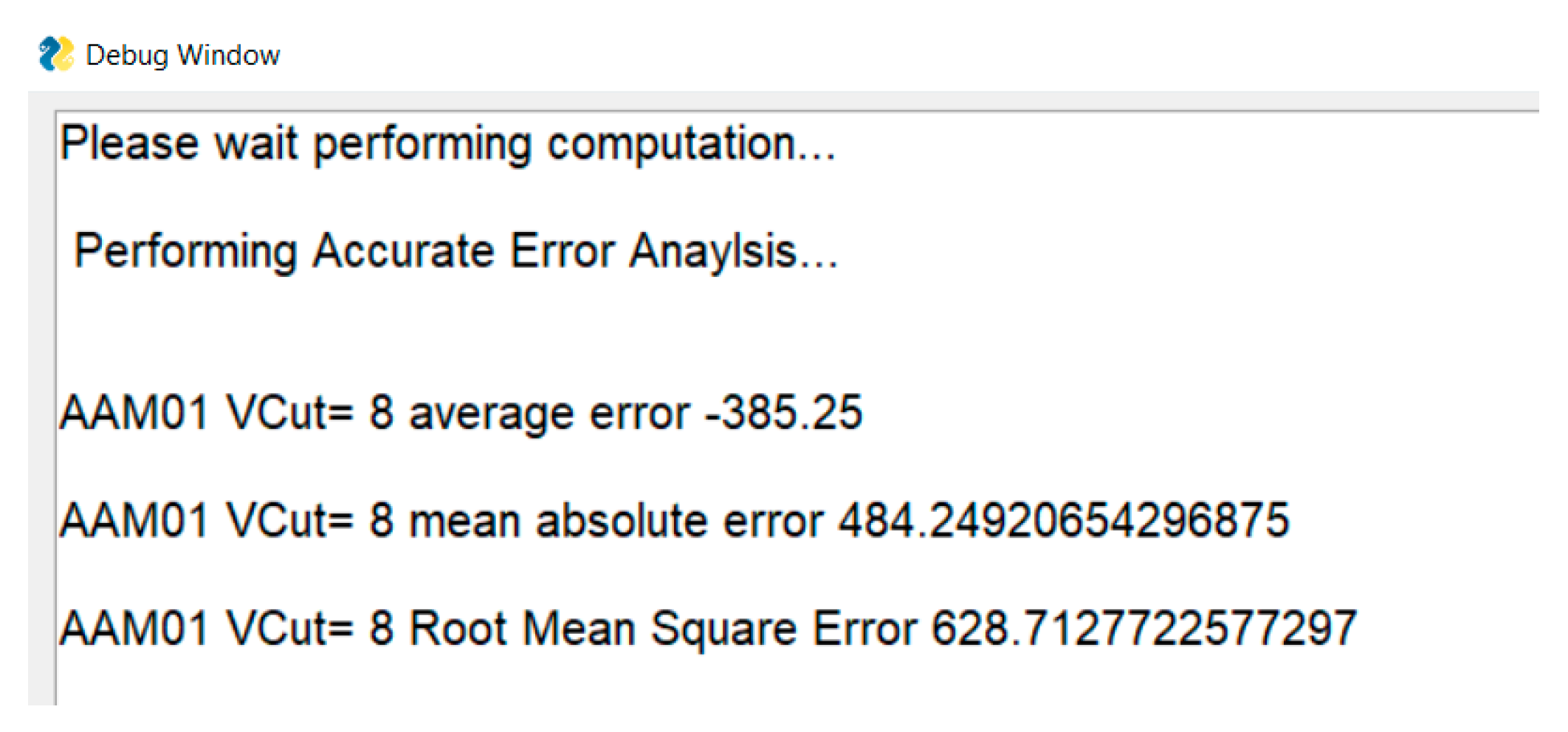
AE, MAE, and RMSE values are printed in a separate debug window, specified in the ‘PrintToDebugWindow.py’ file in the ‘GUI.Utils’ module. An example calculation of error parameters using the GUI for 32-bit approximate adders comprising a 10-bit inexact part is shown in Figure 20, and a similar display for an 8 × 8 AAM01-V8 is shown in Figure 21.
4.2.3. Accuracy Analysis
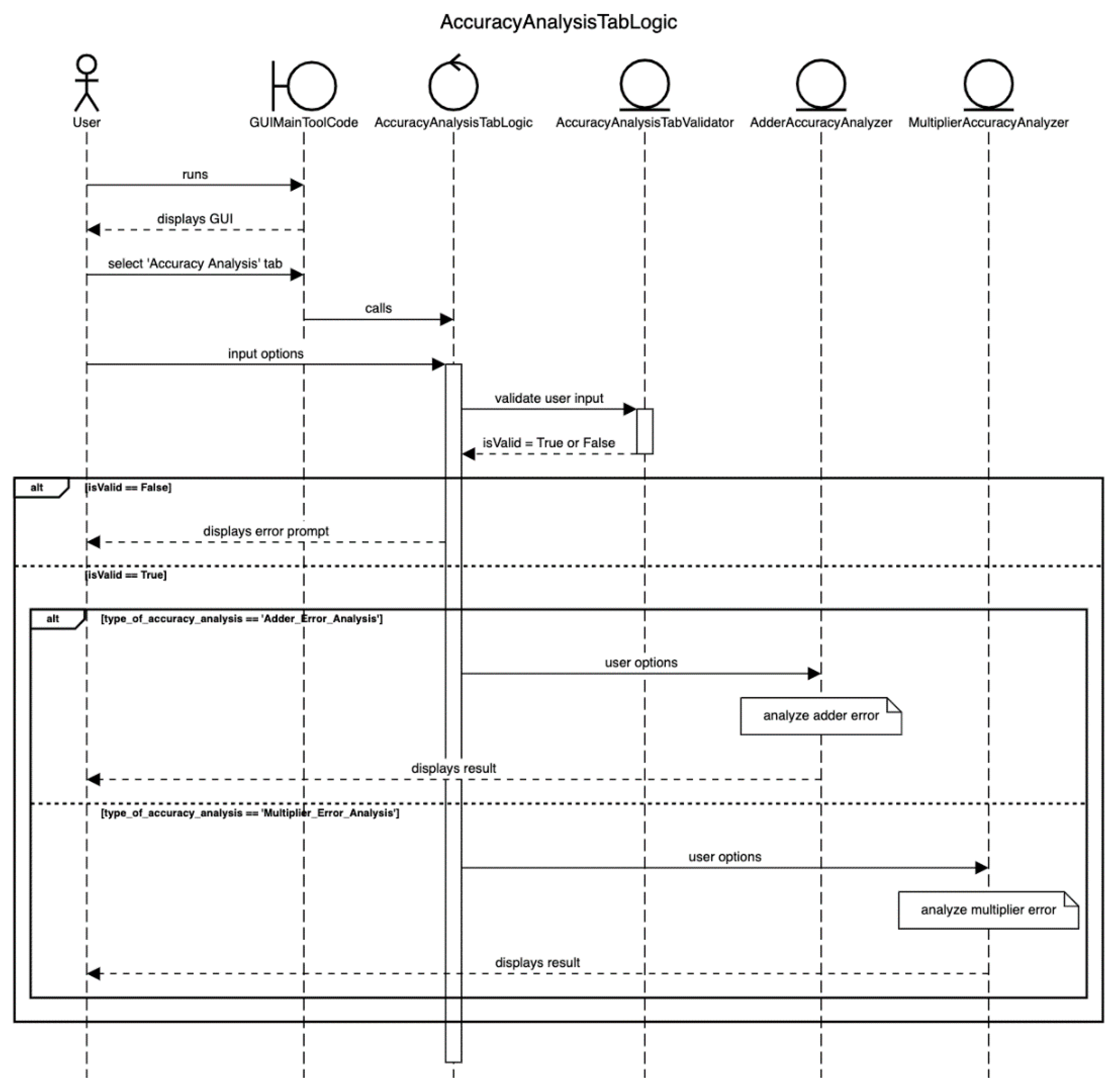
Besides error analysis, accuracy analysis is also incorporated into Approximator to give information about the percentage accuracy of result produced by an approximate adder or multiplier for a user specified input or randomly generated inputs. A sequence diagram depicting the accuracy analysis of approximate arithmetic circuits in Approximator is shown in Figure 22. ‘AccuracyAnalysisTabLogic.py’ in the ‘GUI.Logic’ module runs an appropriate function in the ‘AdderAccuracyAnalyzer.py’ and ‘MultiplierAccuracyAnalyzer.py’ files located in the ‘GUI.Analyzers.AccuracyAnalyzers’ module to analyze the accuracy of approximate adders and approximate multipliers, respectively. These analyzers use the functions given in ‘ApproxAdders.py’ and ‘ApproxMultipliers.py’ to calculate the sum and product corresponding to approximate adders and approximate multipliers, respectively.
Equations (9) and (10) are used by the GUI to calculate the percentage accuracy of results produced by the approximate adder and approximate multiplier. In these equations, and represent the adder/multiplier inputs, respectively, which have to be specified by a user for calculating the accuracy. In Equation (9), and refer to the sum produced by the accurate adder and an approximate adder, respectively. In Equation (10), and refer to the product produced by the accurate multiplier and an approximate multiplier, respectively. Since accurate sum and accurate product are present in the denominator in Equations (9) and (10), it is important to ensure that they are not zero, because the result would otherwise be undefined. As such, is not permitted as a valid input for accuracy analysis in Approximator, and this constraint is specified in Table 10.
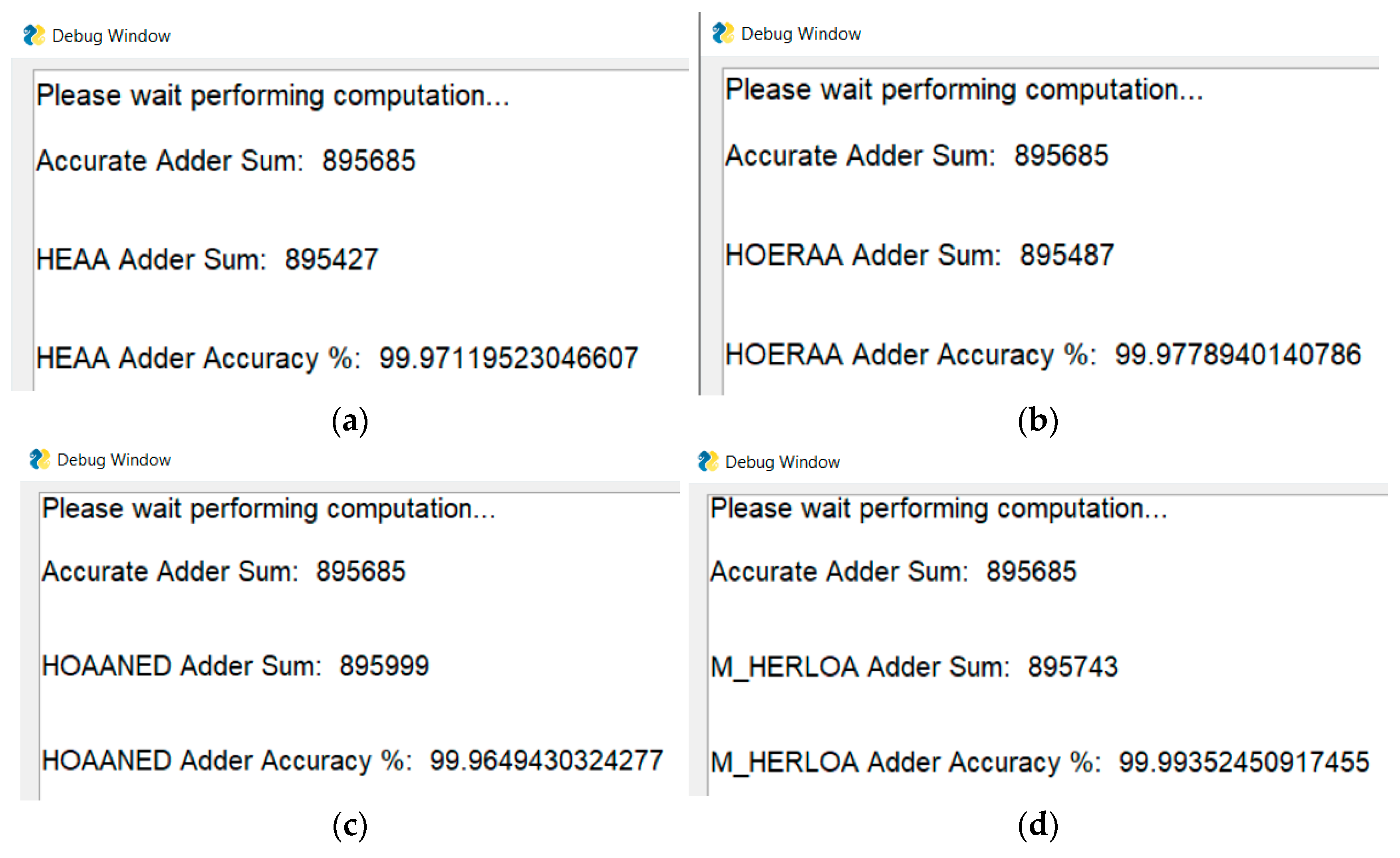
The percentage accuracy of results is printed in a separate debug window, specified in the ‘PrintToDebugWindow.py’ file in the ‘GUI.Utils’ module. An example accuracy calculation for 32-bit approximate adders (HEAA, HOERAA, HOAANED, and M-HERLOA) comprising a 10-bit inexact part using Approximator GUI is shown in Figure 23, where the augend was equal to 343,362 decimal and the value of addend was equal to 552,323 decimal. An example accuracy calculation for an 8 × 8 AAM01-V8 approximate multiplier is shown in Figure 24, where the multiplicand was equal to 235 decimal and the multiplier was equal to 217 decimal.
5. Conclusions
This article presented a software tool for approximate computing called Approximator that can be used to automatically generate Verilog HDL codes of approximate adders and multipliers of any size, as well as perform error and accuracy analyses. The auto-generated HDL codes can be used for synthesis in FPGA and ASIC design environments. The approximate adder types include HEAA, HOERAA, HOAANED, and M-HERLOA, and the approximate multiplier type includes AAM01—these approximate arithmetic circuit architectures have been proposed and validated by us. The usefulness of the approximate adder architectures was demonstrated by considering a DIP application, and the usefulness of the approximate multiplier architecture was demonstrated by considering a DIB application. Approximator has been made available in a convenient GUI form for ease of use, and it can also be used as a CMD tool. The GUI version could be very useful given that it is interactive and easy to use. The associated software packages to be installed in conjunction with the tool have been mentioned, and the tool documentation is also provided for user reference. Example illustrations of Approximator functionalities covering HDL code generation, error analysis, and accuracy analysis have been provided in the form of screenshots that were captured during tool use. Approximator and its source code have been made open-access in GitHub for the benefit of the research community, thus contributing to the reproducibility of research and providing a scope for future development of the tool to promote further effort in design automation for approximate computing.
Author Contributions
Conceptualization, P.B. and D.L.M.; methodology, P.B., R.N. and D.L.M.; software, R.N. and O.M.; validation, P.B., R.N., O.M. and D.L.M.; investigation, P.B. and R.N.; resources, P.B., R.N. and D.L.M.; data curation, P.B. and R.N.; writing—original draft preparation, P.B., R.N. and O.M.; writing—review and editing, P.B.; visualization, P.B., R.N., O.M. and D.L.M.; supervision, P.B. and D.L.M.; project administration, P.B. and D.L.M.; funding acquisition, D.L.M. All authors have read and agreed to the published version of the manuscript.
Funding
This research was funded by the Ministry of Education (MOE), Singapore under an academic research fund Tier-2 grant MOE2018-T2-2-024.
Institutional Review Board Statement
Not applicable.
Informed Consent Statement
Not applicable.
Data Availability Statement
The data has been presented in main text.
Conflicts of Interest
The authors declare no conflict of interest.
References
- Venkataramani, S.; Chakradhar, S.T.; Roy, K.; Raghunathan, A. Approximate computing and the quest for computing efficiency. In Proceedings of the 52nd Design Automation Conference, San Francisco, CA, USA, 8–12 June 2015. [Google Scholar]
- Breuer, M.A. Multi-media applications and imprecise computation. In Proceedings of the 8th Euromicro Conference on Digital System Design, Porto, Portugal, 30 August–3 September 2005. [Google Scholar]
- Zhang, H.; Putic, M.; Lach, J. Low power GPGPU computation with imprecise hardware. In Proceedings of the 51st Design Automation Conference, San Francisco, CA, USA, 1–5 June 2014. [Google Scholar]
- Shoushtari, M.; Rahmani, A.M.; Dutt, N. Quality-configurable memory hierarchy through approximation. In Proceedings of the 14th International Conference on Compilers, Architecture, and Synthesis for Embedded Systems, Taipei, Taiwan, 9–14 October 2011. [Google Scholar]
- Sarwar, S.S.; Srinivasan, G.; Han, B.; Wijesinghe, P.; Jaiswal, A.; Panda, P.; Raghunathan, A.; Roy, K. Energy efficient neural computing: A study of cross-layer approximations. IEEE J. Emerg. Sel. Top. Circuits Syst. 2018, 8, 796–809. [Google Scholar] [CrossRef]
- Sampson, A.; Deitl, W.; Fortuna, E.; Gnanapragasam, D.; Ceze, L.; Grossman, D. EnerJ: Approximate data types for safe and general low-power computation. In Proceedings of the 32nd ACM SIGPLAN Conference on Programming Language Design and Implementation, San Jose, CA, USA, 4–8 June 2011. [Google Scholar]
- Sampson, A.; Nelson, J.; Strauss, K.; Ceze, L. Approximate storage in solid-state memories. In Proceedings of the 46th Annual IEEE/ACM International Symposium on Microarchitecture, Davis, CA, USA, 7–11 December 2013. [Google Scholar]
- Nair, R. Big data needs approximate computing: Technical Perspective. Commun. ACM 2015, 58, 104. [Google Scholar] [CrossRef]
- Panda, P.; Sengupta, A.; Sarwar, S.S.; Srinivasan, G.; Venkataramani, S.; Raghunathan, A.; Roy, K. Cross-layer approximations for neuromorphic computing: From devices to circuits and systems. In Proceedings of the 53rd Annual Design Automation Conference, Austin, TX, USA, 5–9 June 2016. [Google Scholar]
- Jiang, H.; Santiago, F.J.H.; Mo, H.; Liu, L.; Han, J. Approximate arithmetic circuits: A survey, characterization, and recent applications. Proc. IEEE 2020, 108, 2108–2135. [Google Scholar] [CrossRef]
- Scarabottolo, I.; Ansaloni, G.; Constantinides, G.A.; Pozzi, L.; Reda, S. Approximate logic synthesis: A survey. Proc. IEEE 2020, 108, 2195–2213. [Google Scholar] [CrossRef]
- Jiang, H.; Liu, C.; Liu, L.; Lombardi, F.; Han, J. A review, classification, and comparative evaluation of approximate arithmetic circuits. ACM J. Emerg. Technol. Comput. Syst. 2017, 13, 1–37. [Google Scholar] [CrossRef] [Green Version]
- Garside, J.D. A CMOS VLSI implementation of an asynchronous ALU. In Proceedings of the IFIP Working Conference on Asynchronous Design Methodologies, Manchester, UK, 31 March–2 April 1993. [Google Scholar]
- Wanhammar, L. DSP Integrated Circuits, 1st ed.; Academic Press: Cambridge, MA, USA, 1999; ISBN 9780127345307. [Google Scholar]
- Raha, A.; Jayakumar, H.; Raghunathan, V. Input-based dynamic reconfiguration of approximate arithmetic circuits for video encoding. IEEE Trans. VLSI Syst. 2016, 24, 846–857. [Google Scholar] [CrossRef]
- Ercegovac, M.D.; Lang, T. Digital Arithmetic; Morgan Kaufmann: Burlington, MA, USA, 2003; ISBN 978-1558607989. [Google Scholar]
- Jiang, H.; Liu, C.; Maheshwari, N.; Lombardi, F.; Han, J. A comparative evaluation of approximate multipliers. In Proceedings of the IEEE/ACM International Symposium on Nanoscale Architectures, Beijing, China, 18–20 July 2016. [Google Scholar]
- Vai, M.M. VLSI Design; CRC Press: Boca Raton, FL, USA, 2000; ISBN 978-0849318764. [Google Scholar]
- Mahdiani, H.R.; Ahmadi, A.; Fakhraie, S.M.; Lucas, C. Bio-inspired computational blocks for efficient VLSI implementation of soft-computing applications. IEEE Trans. Circuits Syst. I Regul. Pap. 2010, 57, 850–862. [Google Scholar] [CrossRef]
- Balasubramanian, P.; Maskell, D.L. Hardware efficient approximate adder design. In Proceedings of the IEEE Region 10 Conference, Jeju, Korea, 28–31 October 2018. [Google Scholar]
- Balasubramanian, P.; Maskell, D.L. Hardware optimized and error reduced approximate adder. Electronics 2019, 8, 1212. [Google Scholar] [CrossRef] [Green Version]
- Balasubramanian, P.; Nayar, R.; Maskell, D.L.; Mastorakis, N.E. An approximate adder with a near-normal error distribution: Design, error analysis and practical application. IEEE Access 2021, 9, 4518–4530. [Google Scholar] [CrossRef]
- Balasubramanian, P.; Nayar, R.; Maskell, D.L. An approximate adder with reduced error and optimized design metrics. Accepted for publication. In Proceedings of the 17th IEEE Asia Pacific Conference on Circuits and Systems, Penang, Malaysia, 22–26 November 2021. [Google Scholar]
- Balasubramanian, P.; Nayar, R.; Maskell, D.L. Approximate array multipliers. Electronics 2021, 10, 630. [Google Scholar] [CrossRef]
- Balasubramanian, P.; Nayar, R.; Min, O.; Maskell, D.L. Image blending using approximate multiplication. In Proceedings of the IEEE 32nd International Conference on Microelectronics, Nis, Serbia, 12–14 September 2021. [Google Scholar]
- Approximator. Available online: https://github.com/OkkarMin/approximator-tool (accessed on 7 November 2021).
- Approximator Tool Documentation. Available online: https://tool-documentation.vercel.app (accessed on 7 November 2021).
- Zhu, N.; Goh, W.L.; Zhang, W.; Yeo, K.S.; Kong, Z.H. Design of low-power high-speed truncation-error-tolerant adder and its application in digital signal processing. IEEE Trans. VLSI Syst. 2010, 18, 1225–1229. [Google Scholar]
- Albicocco, P.; Cardarilli, G.C.; Nannarelli, A.; Petricca, M.; Re, M. Imprecise arithmetic for low power image processing. In Proceedings of the 46th Asilomar Conference on Signals, Systems and Computers, Pacific Grove, CA, USA, 4–7 November 2012. [Google Scholar]
- Gupta, V.; Mohapatra, D.; Raghunathan, A.; Roy, K. Low-power digital signal processing using approximate adders. IEEE Trans. Comput. Aided Des. Integr. Circuits Syst. 2013, 32, 124–137. [Google Scholar] [CrossRef]
- Dalloo, A.; Najafi, A.; Garcia-Ortiz, A. Systematic design of an approximate adder: The optimized lower part constant-OR adder. IEEE Trans. VLSI Syst. 2018, 26, 1595–1599. [Google Scholar] [CrossRef]
- Seo, H.; Yang, Y.S.; Kim, Y. Design and analysis of an approximate adder with hybrid error reduction. Electronics 2020, 9, 471. [Google Scholar] [CrossRef] [Green Version]
- Bovik, A. Handbook of Image and Video Processing, 2nd ed.; Academic Press: Orlando, FL, USA, 2005; ISBN 978-0080533612. [Google Scholar]
- Wang, Z.; Bovik, A.C.; Sheikh, H.R.; Simoncelli, E.P. Image quality assessment: From error visibility to structural similarity. IEEE Trans. Image Processing 2004, 13, 600–612. [Google Scholar] [CrossRef] [PubMed] [Green Version]
- Chan, W.-T.J.; Kahng, A.B.; Kang, S.; Kumar, R.; Sartori, J. Statistical analysis and modeling for error composition in approximate computation circuits. In Proceedings of the 31st IEEE International Conference on Computer Design, Asheville, NC, USA, 6–9 October 2013. [Google Scholar]
- Balasubramanian, P.; Maskell, D.L. Factorized carry lookahead adders. In Proceedings of the IEEE 14th International Symposium on Signals, Circuits and Systems, Iasi, Romania, 11–12 July 2019. [Google Scholar]
- Synopsys SAED_EDK32/28_CORE Databook. Revision 1.0.0, January 2012. Available online: https://www.synopsys.com/community/university-program/teaching-resources.html (accessed on 27 September 2021).
- Yamamoto, T.; Taniguchi, I.; Tomiyama, H.; Yamashita, S.; Hara-Azumi, Y. A systematic methodology for design and analysis of approximate array multipliers. In Proceedings of the IEEE Asia Pacific Conference on Circuits and Systems, Jeju, Korea, 25–28 October 2016. [Google Scholar]
- Gamma, E.; Helm, R.; Johnson, R.; Vlissides, J.; Booch, G. Design Patterns: Elements of Reusable Object-Oriented Software, 1st ed.; Addison-Wesley: Boston, MA, USA, 1994; ISBN 978-0201633610. [Google Scholar]
- Shinya, T. Pyverilog: A Python-based hardware design processing toolkit for Verilog HDL. In Proceedings of the 11th International Symposium on Applied Reconfigurable Computing, Bochum, Germany, 14–17 April 2015. [Google Scholar]
- NumPy. Available online: https://numpy.org (accessed on 10 June 2021).
- PySimpleGUI. Available online: https://pysimplegui.readthedocs.io/en/latest (accessed on 19 June 2021).
Figure 1.
Block diagram representation of: (a) accurate adder; (b) HEAA; (c) HOERAA; (d) HOAANED; and (e) M-HERLOA. The block diagram of M-HERLOA shown here is representative; the number of sum bits which can be assigned a constant 1 in the inexact part is best decided based on a target application.

Figure 2.
Image processing result for ‘lena’ image obtained using accurate and approximate adders: (a) accurate adder; (b) LOA; (c) LOAWA; (d) APPROX5; (e) HEAA; (f) OLOCA; (g) HOERAA; (h) HOAANED; (i) HERLOA; (j) M-HERLOA.
Figure 2.
Image processing result for ‘lena’ image obtained using accurate and approximate adders: (a) accurate adder; (b) LOA; (c) LOAWA; (d) APPROX5; (e) HEAA; (f) OLOCA; (g) HOERAA; (h) HOAANED; (i) HERLOA; (j) M-HERLOA.

Figure 3.
Image processing result for ‘cameraman’ image obtained using accurate and approximate adders: (a) accurate adder; (b) LOA; (c) LOAWA; (d) APPROX5; (e) HEAA; (f) OLOCA; (g) HOERAA; (h) HOAANED; (i) HERLOA; (j) M-HERLOA.
Figure 3.
Image processing result for ‘cameraman’ image obtained using accurate and approximate adders: (a) accurate adder; (b) LOA; (c) LOAWA; (d) APPROX5; (e) HEAA; (f) OLOCA; (g) HOERAA; (h) HOAANED; (i) HERLOA; (j) M-HERLOA.

Figure 4.
Image processing result for ‘woman with dark hair’ image obtained using accurate and approximate adders: (a) accurate adder; (b) LOA; (c) LOAWA; (d) APPROX5; (e) HEAA; (f) OLOCA; (g) HOERAA; (h) HOAANED; (i) HERLOA; (j) M-HERLOA.
Figure 4.
Image processing result for ‘woman with dark hair’ image obtained using accurate and approximate adders: (a) accurate adder; (b) LOA; (c) LOAWA; (d) APPROX5; (e) HEAA; (f) OLOCA; (g) HOERAA; (h) HOAANED; (i) HERLOA; (j) M-HERLOA.

Figure 5.
Error characteristic plots with error magnitudes given in the X-axis and their percentage occurrence given in the Y-axis for approximate adders: (a) HEAA; (b) HOERAA; (c) HOAANED; (d) M-HERLOA.
Figure 5.
Error characteristic plots with error magnitudes given in the X-axis and their percentage occurrence given in the Y-axis for approximate adders: (a) HEAA; (b) HOERAA; (c) HOAANED; (d) M-HERLOA.

Figure 6.
Architecture of accurate 8 × 8 array multiplier and an illustration of the location of vertical cuts V0 to V10 represented by the dashed lines in red.
Figure 6.
Architecture of accurate 8 × 8 array multiplier and an illustration of the location of vertical cuts V0 to V10 represented by the dashed lines in red.

Figure 7.
AAM architectures resulting from vertical cut V8 made on the accurate 8 × 8 array multiplier shown in Figure 6.
Figure 7.
AAM architectures resulting from vertical cut V8 made on the accurate 8 × 8 array multiplier shown in Figure 6.

Figure 8.
AAM00/AAM01 architectures. For the AAM00 architecture, product bits P8 to P0 were assigned binary 0, and for the AAM01 architecture, product bits P8 to P0 were assigned binary 1.
Figure 8.
AAM00/AAM01 architectures. For the AAM00 architecture, product bits P8 to P0 were assigned binary 0, and for the AAM01 architecture, product bits P8 to P0 were assigned binary 1.

Figure 9.
AAM10/AAM11 architectures. For the AAM10 architecture, product bits P8 to P0 were assigned binary 0, and for the AAM11 architecture, product bits P8 to P0 were assigned binary 1.
Figure 9.
AAM10/AAM11 architectures. For the AAM10 architecture, product bits P8 to P0 were assigned binary 0, and for the AAM11 architecture, product bits P8 to P0 were assigned binary 1.

Figure 10.
Error characteristic plot of AAMs, with error magnitude shown along the X-axis and their percentage occurrence shown along the Y-axis: (a) AAM00-V8; (b) AAM01-V8; (c) AAM10-V8; (d) AAM11-V8.
Figure 10.
Error characteristic plot of AAMs, with error magnitude shown along the X-axis and their percentage occurrence shown along the Y-axis: (a) AAM00-V8; (b) AAM01-V8; (c) AAM10-V8; (d) AAM11-V8.

Figure 11.
Blending of ‘lena’ and ‘mask’ images: (a) ‘lena’ image; (b) ‘mask’ image; (c) accurately blended images; (d) images blended using AAM00-V8; (e) images blended using AAM01-V8; (f) images blended using AAM10-V8; (g) images blended using AAM11-V8.
Figure 11.
Blending of ‘lena’ and ‘mask’ images: (a) ‘lena’ image; (b) ‘mask’ image; (c) accurately blended images; (d) images blended using AAM00-V8; (e) images blended using AAM01-V8; (f) images blended using AAM10-V8; (g) images blended using AAM11-V8.

Figure 12.
Blending of ‘cameraman’ and ‘mask’ images: (a) ‘cameraman’ image; (b) ‘mask’ image; (c) accurately blended images; (d) images blended using AAM00-V8; (e) images blended using AAM01-V8; (f) images blended using AAM10-V8; (g) images blended using AAM11-V8.
Figure 12.
Blending of ‘cameraman’ and ‘mask’ images: (a) ‘cameraman’ image; (b) ‘mask’ image; (c) accurately blended images; (d) images blended using AAM00-V8; (e) images blended using AAM01-V8; (f) images blended using AAM10-V8; (g) images blended using AAM11-V8.

Figure 13.
Blending of ‘woman with dark hair’ and ‘mask’ images: (a) ‘woman with dark hair’ image; (b) ‘mask’ image; (c) accurately blended images; (d) images blended using AAM00-V8; (e) images blended using AAM01-V8; (f) images blended using AAM10-V8; (g) images blended using AAM11-V8.
Figure 13.
Blending of ‘woman with dark hair’ and ‘mask’ images: (a) ‘woman with dark hair’ image; (b) ‘mask’ image; (c) accurately blended images; (d) images blended using AAM00-V8; (e) images blended using AAM01-V8; (f) images blended using AAM10-V8; (g) images blended using AAM11-V8.

Figure 14.
Flowchart describing the use of the GUI version of Approximator.

Figure 15.
Example Approximator GUI window.

Figure 16.
Display of an error message that pops up when a user input does not adhere to the input constraints.
Figure 16.
Display of an error message that pops up when a user input does not adhere to the input constraints.

Figure 17.
Tree layout of files in Approximator GUI.

Figure 18.
Sequence diagram of Verilog code generator in Approximator.

Figure 19.
Sequence diagram of error analysis in Approximator.

Figure 20.
Example calculation and display of AE, MAE, and RMSE for 32-bit approximate adders with a 10-bit inaccurate part using Approximator GUI: (a) HEAA; (b) HOERAA; (c) HOAANED; (d) M-HERLOA.
Figure 20.
Example calculation and display of AE, MAE, and RMSE for 32-bit approximate adders with a 10-bit inaccurate part using Approximator GUI: (a) HEAA; (b) HOERAA; (c) HOAANED; (d) M-HERLOA.

Figure 21.
Example calculation and display of AE, MAE, and RMSE for 8 × 8 AAM01-V8 (i.e., AAM01 approximate array multiplier derived by making vertical cut V8 on an accurate 8 × 8 array multiplier) using Approximator GUI.
Figure 21.
Example calculation and display of AE, MAE, and RMSE for 8 × 8 AAM01-V8 (i.e., AAM01 approximate array multiplier derived by making vertical cut V8 on an accurate 8 × 8 array multiplier) using Approximator GUI.

Figure 22.
Sequence diagram of accuracy analysis in Approximator.

Figure 23.
Accuracy calculation of 32-bit approximate adders comprising a 10-bit inexact part using Approximator GUI: (a) HEAA; (b) HOERAA; (c) HOAANED; (d) M-HERLOA.
Figure 23.
Accuracy calculation of 32-bit approximate adders comprising a 10-bit inexact part using Approximator GUI: (a) HEAA; (b) HOERAA; (c) HOAANED; (d) M-HERLOA.

Figure 24.
Accuracy calculation for 8 × 8 AAM01-V8 using Approximator GUI.


Table 1.
Error metrics (MAE and RMSE) of approximate adders. The adders are of size 32 bits and have a 10-bit inexact part.
Table 1.
Error metrics (MAE and RMSE) of approximate adders. The adders are of size 32 bits and have a 10-bit inexact part.
| Approximate Adder | MAE | RMSE |
|---|---|---|
| LOA | 191.96 | 256.10 |
| LOAWA | 255.70 | 361.74 |
| APPROX5 | 256.22 | 295.71 |
| HEAA | 127.71 | 180.80 |
| OLOCA | 208.07 | 276.63 |
| HOERAA | 127.96 | 165.18 |
| HOAANED | 128.00 | 165.24 |
| HERLOA | 87.71 | 129.15 |
| M-HERLOA | 84.46 | 124.56 |
Table 2.
FPGA-based design metrics of accurate 32-bit adder and approximate 32-bit adders with a 10-bit inexact part.
Table 2.
FPGA-based design metrics of accurate 32-bit adder and approximate 32-bit adders with a 10-bit inexact part.
| Adder | Clock Period (ns) | LUTs | FFs | Power (W) |
|---|---|---|---|---|
| Accurate FPGA Adder | 2.10 | 32 | 97 | 0.209 |
| LOA | 1.89 | 27 | 97 | 0.198 |
| LOAWA | 1.86 | 27 | 97 | 0.198 |
| APPROX5 | 1.84 | 22 | 88 | 0.200 |
| HEAA | 1.89 | 27 | 97 | 0.199 |
| OLOCA | 1.87 | 23 | 73 | 0.187 |
| HOERAA | 1.87 | 23 | 73 | 0.188 |
| HOAANED | 1.87 | 23 | 73 | 0.188 |
| HERLOA | 1.89 | 28 | 97 | 0.199 |
| M-HERLOA | 1.90 | 25 | 79 | 0.190 |
Table 3.
ASIC-based design metrics of 32-bit accurate adder and 32-bit approximate adders with a 10-bit inexact part.
Table 3.
ASIC-based design metrics of 32-bit accurate adder and 32-bit approximate adders with a 10-bit inexact part.
| Adder | Critical Path Delay (ns) | Area (µm²) | Power (µW) |
|---|---|---|---|
| Accurate CLA | 1.17 | 564.60 | 94.33 |
| LOA | 0.96 | 428.36 | 71.77 |
| LOAWA | 0.96 | 413.37 | 68.86 |
| APPROX5 | 0.96 | 424.58 | 73.54 |
| HEAA | 0.96 | 430.65 | 71.49 |
| OLOCA | 0.96 | 420.03 | 66.11 |
| HOERAA | 0.96 | 430.38 | 68.82 |
| HOAANED | 0.96 | 425.36 | 67.73 |
| HERLOA | 0.96 | 443.28 | 74.01 |
| M-HERLOA | 0.96 | 433.94 | 69.11 |
Table 4.
Error metrics of different AAMs calculated for 8 × 8 multiplication.
| Approximate Array Multiplier | MAE | RMSE |
|---|---|---|
| AAM00-V8 | 896.25 | 1024.76 |
| AAM01-V8 | 484.25 | 628.71 |
| AAM10-V8 | 1664.76 | 1736.35 |
| AAM11-V8 | 2174.80 | 2230.78 |
Table 5.
ASIC-type standard cell-based design metrics of accurate and approximate 8 × 8 multipliers.
Table 5.
ASIC-type standard cell-based design metrics of accurate and approximate 8 × 8 multipliers.
| Multiplier | Critical Path Delay (ns) | Area (µm²) | Power (µW) |
|---|---|---|---|
| Accurate Multiplier (Using multiplication operator) | 1.75 | 474.39 | 144.20 |
| Accurate Array Multiplier | 2.00 | 509.47 | 183.80 |
| AAM00-V8 and AAM01-V8 | 1.58 | 187.11 | 50.90 |
| AAM10-V8 and AAM11-V8 | 1.53 | 179.99 | 57.68 |
Table 6.
Features of Approximator.
| Tool Feature | Adder/Multiplier | Name of Approximate Arithmetic Circuit |
|---|---|---|
| Verilog code generation | ASIC-based adder | HEAA |
| HOERAA | ||
| HOAANED | ||
| M-HERLOA | ||
| ASIC-based multiplier | AAM01 with V-cut | |
| FPGA-based adder | HEAA | |
| HOERAA | ||
| HOAANED | ||
| M-HERLOA | ||
| Error analysis | Approximate adders | HEAA |
| HOERAA | ||
| HOAANED | ||
| M-HERLOA | ||
| Approximate multiplier | AAM01 with V-cut | |
| Accuracy analysis | Approximate adders | HEAA |
| HOERAA | ||
| HOAANED | ||
| M-HERLOA | ||
| Approximate multiplier | AAM01 with V-cut |
Table 7.
List of software dependencies and versions used.
| Package | Version Used |
|---|---|
| Jinja2 | 2.11.2 |
| MarkupSafe | 1.1.1 |
| NumPy | 1.19.3 |
| Ply | 3.11 |
| PySimpleGUI | 4.33.0 |
| Pyverilog | 1.3.0 |
| Veriloggen | 1.9.0 |
| Yapf | 0.30.0 |
Table 8.
Specification of Verilog code generator constraints in Approximator.
| Verilog Code Generated | Approximate Adder or Multiplier | Total Number of Bits | # Bits for Inaccurate Part of Approximate Adder or V-Cut for Approximate Multiplier |
|---|---|---|---|
| ASIC (based) adder | HEAA | 4 ≤ total bits ≤ 32 | 3 ≤ inaccurate bits ≤ total bits—1 |
| HOERAA | |||
| HOAANED | |||
| M-HERLOA | |||
| FPGA (based) adder | HEAA | 4 ≤ total bits ≤ 32 | 3 ≤ inaccurate bits ≤ total bits—1 |
| HOERAA | |||
| HOAANED | |||
| M-HERLOA | |||
| ASIC (based) multiplier | AAM01 with V-cut | 3 ≤ multiplicand/multiplier bits ≤ 32 | 0 ≤ V-cut ≤ (multiplicand bits + multiplier bits—3) |
Table 9.
Constraints associated with the error analysis of approximate arithmetic circuits in Approximator.
Table 9.
Constraints associated with the error analysis of approximate arithmetic circuits in Approximator.
| Error Analysis | Approximate Adder or Multiplier | Total Number of Bits | # Bits for Inaccurate Part of Approximate Adder or V-Cut for Approximate Multiplier |
|---|---|---|---|
| Approximate adder | HEAA | 4 ≤ total bits ≤ 32 | 3 ≤ inaccurate bits ≤ total bits—1 |
| HOERAA | |||
| HOAANED | |||
| M-HERLOA | |||
| Approximate multiplier | AAM01 with V-cut | 3 ≤ multiplicand/multiplier bits ≤ 32 | 0 ≤ V-cut ≤ (multiplicand bits + multiplier bits—3) |
Table 10.
Constraints associated with the accuracy analysis of approximate arithmetic circuits in Approximator.
Table 10.
Constraints associated with the accuracy analysis of approximate arithmetic circuits in Approximator.
| Accuracy Analysis | Approximate Adder or Multiplier | Total Number of Bits | Number of Inaccurate Bits for Approximate Adder or V-Cut for Approximate Multiplier | First and Second Unsigned Decimal Number |
|---|---|---|---|---|
| Approximate adder | HEAA | 4 ≤ total bits ≤ 32 | 3 ≤ inaccurate bits ≤ total bits−1 | # |
| HOERAA | ||||
| HOAANED | ||||
| M-HERLOA | ||||
| Approximate multiplier | AAM01 with V-cut | 3 ≤ multiplicand/multiplier bits ≤ 32 | 0 ≤ V-cut ≤ (multiplicand bits + multiplier bits—3) |
# Both numbers cannot be zero simultaneously.
Publisher’s Note: MDPI stays neutral with regard to jurisdictional claims in published maps and institutional affiliations. |
© 2022 by the authors. Licensee MDPI, Basel, Switzerland. This article is an open access article distributed under the terms and conditions of the Creative Commons Attribution (CC BY) license (https://creativecommons.org/licenses/by/4.0/).
Share and Cite
MDPI and ACS Style
Balasubramanian, P.; Nayar, R.; Min, O.; Maskell, D.L. Approximator: A Software Tool for Automatic Generation of Approximate Arithmetic Circuits. Computers 2022, 11, 11. https://doi.org/10.3390/computers11010011
AMA Style
Balasubramanian P, Nayar R, Min O, Maskell DL. Approximator: A Software Tool for Automatic Generation of Approximate Arithmetic Circuits. Computers. 2022; 11(1):11. https://doi.org/10.3390/computers11010011
Chicago/Turabian StyleBalasubramanian, Padmanabhan, Raunaq Nayar, Okkar Min, and Douglas L. Maskell. 2022. "Approximator: A Software Tool for Automatic Generation of Approximate Arithmetic Circuits" Computers 11, no. 1: 11. https://doi.org/10.3390/computers11010011
Note that from the first issue of 2016, this journal uses article numbers instead of page numbers. See further details here.