Abstract
In the field of 3D point cloud data, the 3D representation of objects is often affected by factors such as lighting, occlusion, and noise, leading to issues of information loss and incompleteness in the collected point cloud data. Point cloud completion algorithms aim to generate complete object point cloud data using partial or local point cloud data as input. Despite promising results achieved by existing methods, current point cloud completion approaches often lack smooth and structural consistency, resulting in a messy overall structure. To address these shortcomings in point cloud completion, we propose a point cloud generative method based on surface consistency and scale rendering. In addition, to solve the limitation of existing methods that mainly focus on geometric features in 3D point cloud completion and do not make full use of color information, we introduce an object reconstruction method based on texture and geometric features. Extensive experiments demonstrate that our proposed methods exhibit superior performance in terms of local details and overall object structure.
1. Introduction
With the development of 3D vision, the three-dimensional data structure and perception of objects have rapidly advanced in various applications, including industry, military, and agriculture. Three-dimensional object data can be easily acquired using 3D scanning devices and depth cameras. Three-dimensional point clouds can be viewed as a collection of unordered and irregular points collected from the surface of an object, where each point consists of three-dimensional coordinates and additional information [1]. However, in practical applications, the raw point clouds generated by these devices are often sparse and noisy and may exhibit significant missing areas due to limitations in scanning, data loss, or partial occlusion [2,3].
Due to the irregularity and permutation invariance of data, deep learning methods have limitations in handling 3D point clouds. Particularly, in the process of object perception and detection, we often perform object detection and perception based on information from local and partial perspectives, which cannot ensure accurate and comprehensive object detection and perception from all viewpoints. This leads to issues such as inaccurate object perception, imprecise localization, and the inability to determine the object’s pose. For instance, Lawin et al. [4] proposed the projection of 3D point clouds onto a 2D plane through multiple virtual camera viewpoints. They used a multi-branch fully convolutional network to predict category scores for each pixel on the synthesized image. The final semantic labels were obtained by merging predictions from different viewpoints. Tatarchenko et al. [5] introduced slice convolutions for dense point cloud semantic segmentation. Overall, the performance of these methods is greatly influenced by factors such as viewpoint selection and occlusion, leading to significant structural and information loss [6]. These limitations make it challenging to further analyze shape, renderings, and pose analysis. Therefore, the task of inferring a complete shape from partial observations is necessary and crucial in practical applications, as it can facilitate various downstream tasks [7]. An example of this is a new view synthesis method based on point cloud completion proposed by VET [8]. The method utilizes point cloud data and optimizes the synthesized new views through point cloud completion. Pseudo-lidar [9] introduces a pseudo-lidar point cloud interpolation network to generate high-quality point cloud sequences in both temporal and spatial dimensions. The point cloud interpolation network resolves the frame rate mismatch issue between cameras and lidars.
Three-dimensional point cloud completion is a task in the fields of computer vision and computer graphics, aiming to generate complete 3D models from partial or incomplete 3D point cloud data. The goal of this task is to fill in the missing parts or information in the point cloud to make the representation of objects or scenes more complete and accurate. Given the irregularity and unordered nature of point cloud data, some solutions leverage intermediate representations of deep neural networks. These solutions take forms such as multi-view synthesized depth maps [10], grid and voxel representations [11], etc., to learn representations that aid in solving computer vision tasks such as classification [4,5,6,12,13], segmentation, and reconstruction [14,15,16,17].
For point-based methods, operations are directly performed on the point cloud. Due to the unordered and irregular nature of point cloud data, conventional convolutional neural networks cannot be directly applied to non-uniform point clouds. PointNet [12] is a pioneering work in this direction, learning point-wise features through multiple perception layers and aggregating global features through max-pooling layers. However, PointNet fails to capture local structures caused by points in metric space, limiting its ability to recognize fine-grained patterns and generalize to complex scenes. PointNet++ [13] introduces hierarchical neural networks, recursively processing point cloud data, but it does not fully exploit the local details of the point cloud. HyperPC [18] proposes a hyper-spherical module that outputs hyper-spherical embeddings, which transform and normalize the embeddings from the encoder onto a unit hyper-sphere, enhancing the performance of point cloud completion.
While existing methods have achieved promising results, current point cloud completion methods tend to lose local structural details, typically lacking smooth and structural consistency, resulting in a somewhat disorderly structure. Addressing these shortcomings in point cloud completion, we propose a point cloud generative network based on surface consistency and scale rendering. The main contributions of this paper are as follows:
- (1)
- We propose a novel 3D computer vision algorithm for point cloud completion and object reconstruction, addressing the issue of missing object structure and information caused by noise and occlusion. This involves completing and reconstructing the 3D point cloud of the object to enhance the perception of the complete object structure.
- (2)
- We designed a point cloud object completion algorithm based on surface consistency and scale rendering. Through surface-based consistency constraints, surface consistency information is obtained to address issues in existing point cloud completion algorithms, such as insufficient surface details, roughness, high noise, and lack of smoothness. Depth and scale information rendering is utilized to obtain structural consistency constraints, improving surface detail smoothness and overall structural integrity in point cloud completion.
- (3)
- We introduce a 3D object point cloud generation method based on pixel-level fusion of color and geometry information. By employing pixel-level fusion of color and geometry information, this method fully utilizes both color and geometric information for object reconstruction, enhancing the completeness and accuracy of object reconstruction.
2. Related Work
Various methods have been proposed in the fields of computer graphics, 3D computer vision, and robotics for representing 3D geometric shapes for rendering and reconstruction purposes. These methods involve a trade-off between fidelity, efficiency, and compression capability. Three-dimensional reconstruction faces challenges in handling large-scale scenes and complex lighting conditions. Additionally, the methods are often progressive, requiring a substantial number of images from different viewpoints. In cases of information loss and incomplete object information, it becomes challenging to reconstruct the entire object. Consequently, the generation of models with insufficiently broad and comprehensive input perspectives may lead to occlusions and holes in the models [19,20,21].
Point cloud completion refers to inferring the complete geometric shape of missing regions from an incomplete 3D object. Previous methods typically relied on predicting the complete point cloud based on a global shape representation extracted from the incomplete input. However, global representations are often affected by the loss of local structural details in incomplete point clouds. To address this issue, the skip-attention network (SA-Net) was proposed for 3D point cloud completion in [2]. The skip-attention mechanism effectively leverages local structural details of incomplete point clouds, selectively transmitting geometric information from local regions of the incomplete point cloud when inferring missing parts to generate a complete point cloud at different resolutions. A novel decoder with hierarchical folding was introduced to preserve the structure for shape completion. In [22], novel point cloud upsampling network based on generative adversarial network, named PU-GAN, was introduced. Since point clouds obtained from range scans are often sparse, noisy, and non-uniform, PU-GAN is designed to learn rich point distributions from the latent space and upsample points on the object surface. To achieve an effective GAN network, these authors constructed an up–down–up expansion unit in the generator, which uses error feedback and self-correction to upsample point features. Additionally, a self-attention unit was built to enhance feature integration.
Most 3D shape completion methods heavily rely on partial–complete shape pairs and are trained in a fully supervised manner. Despite their impressive performance on in-domain data, they often yield unsatisfactory results when generalized to other forms or real-world partial scans due to domain differences. ShapeInversion [23], in contrast to previous fully supervised approaches, introduces the concept of generative adversarial network inversion into shape completion. ShapeInversion utilizes a GAN pretrained on complete shapes and achieves shape completion by searching for the optimal latent code that reconstructs the complete shape given a partial input. In [1], a novel conditional generative adversarial network was introduced to generate dense 3D point clouds for various object categories, including color information, without supervision. To overcome the challenge of capturing intricate details at high resolution, these authors proposed a point transformer that gradually expands the network using graph convolutions. In [24], a novel style-based point generator with adversarial rendering (SpareNet) for point cloud completion was proposed. It leverages channel-wise attention EdgeConv to fully exploit local structures and global shapes in point features. Treating shape features as style codes, modulating normalization layers during folding greatly enhances their capability. Addressing the limitation of existing point supervision in effectively reflecting the perceptual quality of reconstructed points, this generator introduces the projection of completed points into depth maps and employs adversarial training to advocate perceptual realism from different viewpoints.
Unlike pixels arranged in regular grids in images, 3D shapes are represented by points in continuous 3D space without a common structure. Consequently, 3D GANs often generate point clouds with significant irregularities, where points are unevenly distributed on the shape surface [23]. Therefore, addressing the above issues, we propose a 3D point cloud generation and reconstruction method based on surface consistency and scale rendering.
3. Method
3.1. Overall Framework
In our proposed method, we present a 3D object point cloud generation algorithm under the condition of incomplete information. Firstly, to address the information and structural deficiencies in 3D object point clouds caused by issues such as camouflage and occlusion, we employ a generative adversarial network for information completion. Subsequently, object reconstruction is achieved through surface consistency and structural consistency. Furthermore, pixel-level fusion is applied to combine point cloud geometric features with image texture features. Ultimately, the 3D object’s point cloud information completion and reconstruction are realized, and the algorithm framework is illustrated in Figure 1.
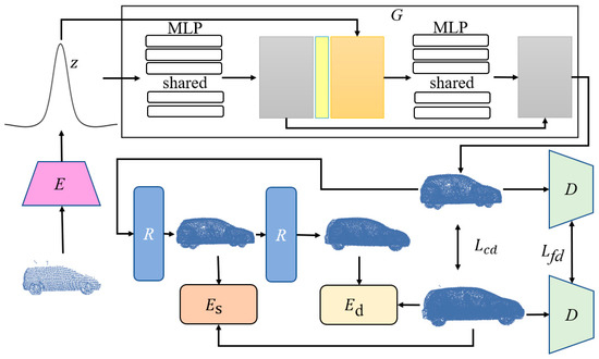
Figure 1.
The algorithm framework for 3D object recognition under incomplete information conditions. In the figure, G represents the generator, R denotes the refinement stage, is the structural consistency renderer, stands for the surface consistency term, Lcd represents the Chamfer distance, Lfd represents feature distance, and D is the discriminator.
Given a partial and low-resolution point cloud X as input, the generation network completes X into a rough point cloud using an encoder E and a generator G composed of multilayer perceptions (MLPs). The encoder E embeds X into a shape code z, and the generator G utilizes the shape code z to synthesize a rough point cloud as output. Simultaneously, a refinement stage is employed, utilizing surface consistency terms and scale structure rendering to further refine the point cloud data, resulting in the output of a final, improved-quality, complete, and high-resolution point cloud object.
3.2. Point Cloud Completion Network Based on Shape Priors
We adopted the encoder from PCN [3] as our encoder and drew inspiration from PCN’s [3] decoder to construct our generator. The encoder is responsible for summarizing the geometric information of the input point cloud into a feature vector . The decoder is responsible for generating the output point cloud from the feature vector z. Our proposed decoder combines the advantages of a fully connected decoder and a folding-based decoder in a multi-stage point-generation process [3]. Additionally, we employ a discriminator similar to rGAN [25] and TreeGAN [26] and a refinement stage R composed of a residual network based on minimum density sampling, which is similar to PointNet [12]. We employ the discriminator from rGAN, which can perform feature extraction to capture more geometric details and compute feature distance losses since structural losses typically only focus on the low-level regularity of point clouds, and this can perform feature matching in observation space and align geometric shapes more semantically. Additionally, due to the limitation of capacity, autoencoders may overlook some structures already present in the input point cloud. Therefore, we employ a combined point-wise residual refiner, learning point-wise residuals for refinement to generate fine-grained structures.
We conduct deep training of the generative adversarial network with the three-dimensional shape of the object, capturing a rich distribution of geometric shapes and semantics. The trained GAN is utilized as a prerequisite for effectively completing shapes and is generalized to unknown shapes.
During the training process, we use chamfer distance loss and feature distance loss as adversarial losses. We also introduce surface consistency and structural scale consistency terms, as described in Section 3.3. The adversarial generation network is trained on the point cloud form of three-dimensional shapes by adjusting the parameters θ of the generator G. Given partial input point cloud data, the adversarial generation network generates the point cloud data of shape by obtaining the latent vector through the encoder. The generation process is expressed as the following equation:
In the initialization stage, we extract the latent vector z. Subsequently, based on the generator G parameterized by θ as defined in the above equation and through the refinement stage R, we infer a complete shape from the given partial shape .
3.3. Object Reconstruction Based on Surface Consistency and Scale Rendering
Our goal is to complete and generate a complete dense shape from a partially input 3D point cloud object through the encoder E, obtaining a latent vector . During the training process, we iteratively optimize the shape code and object structure from the input random variables. To achieve this, we introduce two optimization modules, and , which regularize the surface consistency and structural scale of the entire shape during the training of the point cloud completion network, in addition to the adversarial loss.
3.3.1. Surface Consistency Module
This module measures the alignment between the generated 3D point cloud and the reconstructed object surface.
Here, represents the set of 3D points within the k neighborhood of the 3D point cloud . Ideally, the generated and completed 3D points should perfectly align with the object’s surface, resulting in a surface consistency value of zero and thus generating zero error residuals. Given the 3D point cloud and the object point cloud , the transformation relationship between the two point clouds is expressed as in Equation (3).
Whereas, the transformation relationship between the two sets of object point clouds in Equation (3) is obtained through a point cloud registration method denoted as M, and the registration process is illustrated in Figure 2. Based on the solved transformation relationship between the two sets of object point clouds in Equation (3), we can approximate the solution of the 3D point in the completed point cloud within the object point cloud, as shown in Equation (4).
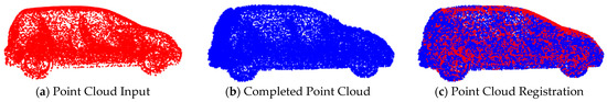
Figure 2.
Point cloud registration, where (a) represents the input point cloud, (b) depicts the completed point cloud, and (c) shows the point cloud after registration.
Therefore, the alignment degree of the 3D point with the k-nearest neighbor object surface is expressed in Equations (5) and (6).
In Equations (5) and (6), D represents the distance from the 3D point coordinates to the surface of the k-nearest neighbor region of in the object point cloud.
Whereby, the transformation of 3D points to the object point cloud results in a subset of the k-nearest neighbor 3D point cloud, as illustrated in Figure 3.
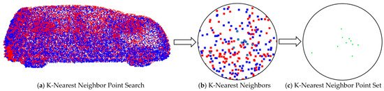
Figure 3.
Search for the k-nearest neighbor point set on the object point cloud. Here, (a) depicts the k-nearest neighbor search on the registered image, (b) shows the k-nearest neighbor region, and (c) illustrates the k-nearest neighbor point set.
However, in practice, using only the surface consistency term may lead to inaccurate shape estimates—much larger than their actual size [16]. This issue has been confirmed in [16]. To address this problem, we employ a rendering loss that provides point-to-point depth supervision and enforces contour consistency to penalize cases where the shape exceeds its expected boundaries.
3.3.2. Object Point Cloud Scale Rendering
Following the methods in references [4,16], we construct a differentiable ray-tracing object point cloud scale renderer between the point cloud and the image plane of the camera projection. Unlike previous approaches, which reconstruct based on multi-view images using the camera coordinate system, we perform 3D object point cloud completion and reconstruction based on partially input 3D point data. Simultaneously, by applying perspective projection to the 3D points, we project the 3D object point cloud onto the image plane to create a projection plane. Within the range of ray distances between the projection plane and the 3D object points, we perform discrete depth-value sampling. For each 3D point , the coordinates in the pixel coordinate system are given by the following:
The process of obtaining the depth map of the object point cloud for the image is illustrated in Figure 4:
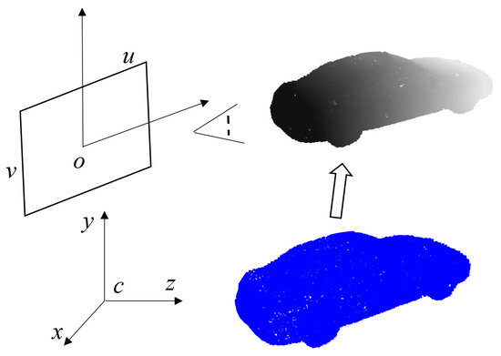
Figure 4.
Schematic illustration of the point cloud depth map, where the blue represents the original point cloud image, and the gray depicts the depth map information of the point cloud.
For each pixel point p on the image projection plane, we generate a ray in camera coordinate space, where is the optical center of the camera, is a point on the ray, t is a real parameter representing the position of the point on the ray, and D is the direction vector of the ray. We sample N discrete values along each ray, with the upper and lower bounds of the depth range determined by the current object position and size.
The probability value at each sampled point on the ray can be obtained by transforming the sampled point to the object coordinate frame and obtaining the distance from the object point cloud surface. The probability encodes the probability of a given point being occupied by the object or belonging to free space. A piecewise linear function is applied to represent the predicted occupancy probability values, as shown in Equation (8):
where is the distance from the point on the ray to the object point cloud, and δ represents the cutoff threshold controlling transition smoothness, set to a fixed value of δ = 0.01 in the experiments.
We represent the likelihood of a point on the ray being inside or outside the object in the form of an event probability. For tracking points along the ray, assuming the i-th point is on the object, based on the principle that the ray either terminates or escapes without any other possibilities, the points before the i-th point must not be on the object. That is, the probability of the i-th point being on the object is expressed as follows in Equation (9):
where is the probability of the i-th point being on the object O, and is the probability that the point on the ray does not terminate.
Based on the event probability in the above equation, we limit the object’s scale range based on the distance values of points. The depth value at each pixel p can be calculated as the expected depth value of the terminating point, as shown in Equation (10). To maintain consistency, we set the depth value associated with the escape probability to a constant value of 1.1dmax, as done in [4,16].
We do not need to segment the image or perform ray tracing in continuous space, and there is no need to discretize the object model. The size constraint term for the object point cloud is as follows:
where ω represents the non-overlapping pixel region generated by the projection of the original point cloud and the generated object point cloud on the image, and M is the size of ω. In the depth image, pixels in the non-overlapping region are assigned the same depth value as . This provides important contour supervision for training, enforces object point cloud size constraints through ray escaping, and penalizes generated points located outside the boundaries of the object point cloud.
3.3.3. Loss Function
The loss function describes the differences between the real point cloud and the generated point cloud. Our loss function includes not only the generation loss but also the surface consistency loss and the scale rendering loss. The overall loss function is expressed as follows.
Here, L and , , and represent the total loss, surface consistency term loss, scale rendering loss, and generation loss, respectively; and , , and are the corresponding loss weights.
3.4. Iterative Strategy-Based Point Cloud Texture Construction
Differing from the approach used by make-it-3D, which reconstructs color and texture by corresponding depth maps and images, our method directly assigns colors to the 3D point cloud. However, this approach introduces ambiguity when multiple points are on the same projection line may overlap in the image. Therefore, we propose a new iterative strategy-based nearest-neighbor point cloud texture assignment method.
By projecting the object point cloud onto the image plane, we obtain the contour region of the point cloud on the image plane. For points located on the contour, we construct a plane equation. The point cloud object is then sliced according to the plane equation. Color assignment is performed for 3D points on one side of the plane, and no color assignment is performed for points on the other side. The specific projection process is illustrated in Figure 5.
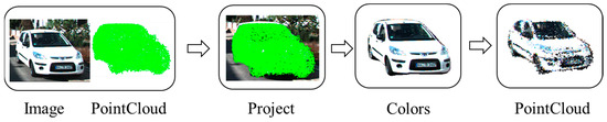
Figure 5.
Schematic diagram of texture mapping for the object point cloud. Here, “Image” and “Pointcloud” represent the inputs; “Project” illustrates the projection process, where color information is obtained on the image (“Colors”); and the final output consists of point cloud data with texture information.
During the point-cloud-generation process, existing methods for generating color and texture in point clouds are often rough and inaccurate due to the lack of color and texture information in the generated point cloud. Therefore, we propose an iterative strategy to construct clean color and texture information in the point cloud from multi-view observations.
We first construct a projected image on the image plane based on the camera projection model from the observed viewpoint o using the object point cloud data, assigning color and texture to the point cloud data. As the number of observed viewpoints of the object point cloud increases, the coloring and refinement of the object point cloud are continued. To avoid introducing three-dimensional points with conflicting colors but overlapping with existing points from different viewpoints, we continually project the three-dimensional object point cloud onto the image plane of new viewpoints to generate an image region caused by viewpoint differences, using the differentiated image region to assign values to the object point cloud. Because at different spatial positions, the projection of 3D points onto the image may overlap or be nested, we use the spatial plane equation method to divide the 3D points into foreground points and occluded points from a certain viewpoint. This is used to differentiate and selectively perform correct texture editing on the point cloud.
The detailed algorithmic procedure is illustrated in Algorithm 1.
| Algorithm 1: Point cloud texture editing. |
| Input: Car point cloud data, C; camera image data, F; camera intrinsic matrix, K; transformation matrix from LiDAR coordinate system to camera coordinate system, T; Output: Colored point cloud data, O; 1 Obtain completed point cloud data for the car object, D, and camera image data, F; 2 Calculate the projection of the car point cloud onto image coordinates, P; 3 for each point in the car object point cloud do 4 Calculate pixel projection coordinates 5 Append to P; 6 end for 7 8 For each pixel coordinate , obtain the projected contour coordinate set S; 9 for each coordinate in the car object point cloud do 10 Obtain the three-dimensional coordinates of the car point cloud corresponding to the pixel coordinates; 11 if () in S 12 Append to H; 13 end if 14 end for 15 Construct the plane equation: |
| 16 Solve the equation using the least squares method: |
| 17 for each coordinate in the car object point cloud do 18 Calculate the distance from the spatial point to the spatial plane, : |
| If it is less than 0, it indicates that it is located in front of the viewpoint. 19 if then 20 Color edit using the color information from ; 21 end if 22 end for |
4. Experimental Results
Experimental Details: We employed Adam optimizers with and for both the generator and discriminator networks, with a learning rate of . The empirical values for , , and were set to 100, 2.5, and 0.5, respectively. We utilized the same discriminator network architecture as in r-GAN [25] and TreeGAN [26]. The discriminator was updated five times per iteration, while the generator was updated once.
Evaluation Criteria: We employed Chamfer distance (CD) and Earth mover’s distance (EMD) to assess the fidelity and uniformity of the generated shape set compared to shapes in the test set. EMD is particularly informative for local characteristics, as it performs bijection matching between two point clouds. CD is a widely used metric due to its computational efficiency. We used the CD score to evaluate shape completion performance.
Datasets: We conducted experiments on both the ShapeNet [27] dataset and the KITTI [28] dataset. The ShapeNet dataset is a large-scale 3D model dataset primarily used for 3D object recognition and understanding. It encompasses a vast collection of 3D models representing various object categories such as cars, airplanes, sofas, etc., in the form of point cloud shapes. The KITTI dataset primarily focuses on computer vision tasks related to autonomous driving and vehicle-related applications. It includes a series of real-world car point cloud data obtained from radar scans.
4.1. Ablation Study
As shown in Figure 6, to validate the effectiveness of the proposed method, we performed point cloud completion on car objects from the ShapeNet dataset both before and after applying surface consistency constraints. As shown in Figure 6a, before the surface constraints, the point cloud surface of the car object contains a significant amount of noise points. After applying the surface constraints, as shown in Figure 6b, the point cloud surface of the car object has been improved. Therefore, from the results of point cloud completion, it can be observed that the surface constraints lead to a significantly smoother point cloud surface, demonstrating the effectiveness of the proposed module.
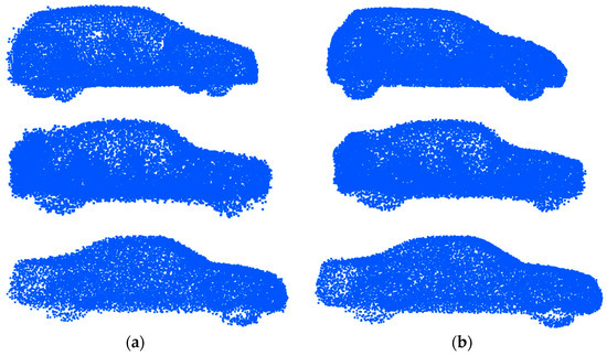
Figure 6.
Surface consistency. Comparison of the results of object point cloud completion before and after surface consistency constraints. Here, (a) represents the point cloud before surface constraints, and (b) represents the point cloud after surface constraints.
Simultaneously, we conducted point cloud completion experiments on car point cloud data both before and after structural scale consistency constraints. As shown in Figure 7, from the experimental results, it can be observed that after the application of structural scale consistency constraints, the scale of the object point cloud is constrained within a reasonable range, leading to the generation of structures that better align with the original true point cloud data.
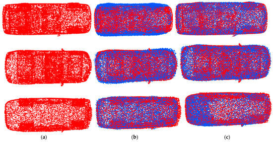
Figure 7.
Structural scale consistency. Comparison of object point cloud completion before and after structural scale consistency constraints. Here, (a) is the ground truth point cloud, (b) is the point cloud before constraints, and (c) is the point cloud after constraints.
The red point cloud represents the ground truth point cloud, and the blue point cloud represents the generated point cloud.
4.2. Quantitative Comparative Experiments
As shown in Table 1 and Table 2, we conducted comparative experiments on point cloud models of airplanes, cars, sofas, and ships from the ShapeNet dataset. We compared our proposed point cloud completion method with state-of-the-art methods SpareNet, PCN, Snowflake [29], and PMP-Net++ [30] based on the CD and CMD metrics, where the bold ones are the optimal results. The experimental results in terms of CD and CMD demonstrate the outstanding performance of our method.

Table 1.
Completion comparison on ShapeNet based on CD × 103 (lower is better).
Table 2.
Completion comparison on ShapeNet based on EMD × 103 (lower is better).
Based on the results in Figure 8, we conducted comparative experiments on point cloud completion results for various shape categories, including airplanes, cars, sofas, and ships, on the ShapeNet dataset. The experimental results demonstrate that our proposed method is capable of generating detailed structures with shape and exhibits competitive results in terms of surface smoothness on datasets such as airplanes, cars, and sofas. Additionally, our method demonstrates superior performance in terms of scale and details.
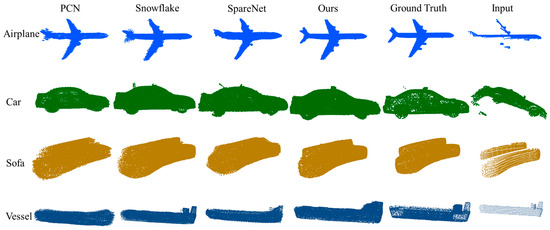
Figure 8.
Comparative experiment on point cloud completion results among different methods.
At the same time, we conducted qualitative experiments on our proposed method. Since there is no ground truth on the KITTI dataset, we only performed qualitative experiments. From the experimental results, it could be seen that the method, using LiDAR point cloud data as input, could effectively complete the point cloud. The completion results are shown in Figure 9.
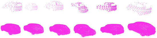
Figure 9.
Point cloud completion results for the KITTI dataset.
Moreover, since many existing methods often generate point cloud data without color and texture information, we also restored the texture and color of the object to some extent through point cloud projection. This can help obtain more information about the object and richer details. For the car in the KITTI dataset, the color assignment results are shown in Figure 10. From the figure, it can be observed that our proposed method effectively assigns colors to the point cloud object of the car.
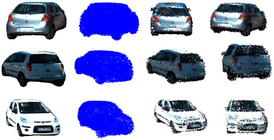
Figure 10.
Texture coloring, where the left side shows the image information of the car and the point cloud data of the car in blue, while the middle and right images display the point cloud data with assigned colors.
Finally, we conducted a completion example on the KITTI dataset. Using the point cloud data obtained from the LiDAR and corresponding image data as input, we first extracted the point cloud of the car by identifying the points falling on the outline of the object vehicle. We then completed the shape of the car point cloud. Next, we projected the completed car point cloud onto the image and edited the color of the point cloud. Finally, we inserted the completed car point cloud coordinates into the LiDAR point cloud. The example results are shown in Figure 11.
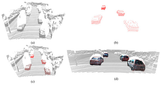
Figure 11.
Point cloud completion example, where (a) represents the input point cloud, (b) is the LiDAR point cloud data of the car, (c) depicts the position of the car LiDAR point cloud in the LiDAR data, and (d) shows the position of the completed colored point cloud in the LiDAR data.
5. Conclusions
This paper introduces a point cloud generation network based on surface consistency and scale rendering. It is capable of simultaneously completing the point cloud while considering both the surface consistency and structural size constraints of the object point cloud. We enhance the smoothness and surface consistency of the point cloud object by introducing a surface consistency component. Additionally, we address the issue of erroneous shape structure estimation resulting from the use of only surface consistency by introducing size constraints. Furthermore, we employ an iterative strategy-based point cloud color assignment method to enrich the color and texture information of the point cloud object. Extensive experiments on various types of object point clouds demonstrate that our method can effectively synthesize high-quality point clouds and exhibits superior performance.
Our proposed method also has some limitations. While our method achieves good results on relatively smooth objects by utilizing surface consistency constraints, it may encounter limitations when dealing with point clouds of objects with high sharpness. This is because the surface consistency term tends to smooth out the sharpness of the object point cloud surfaces in order to obtain smoother surfaces.
Author Contributions
Conceptualization, M.Q.; methodology, C.Y.; formal analysis, C.Y.; investigation, C.Y.; resources, Z.Z.; writing—original draft preparation, C.Y.; visualization, Z.Z.; supervision, J.P.; project administration, Y.X. All authors have read and agreed to the published version of the manuscript.
Funding
This research is supported by The Nature Science Foundation of Shaanxi under grant 2022JQ-653 and The Fundamental Research Funds for the Central Universities, Northwestern Polytechnical University (no. D5000210767).
Data Availability Statement
Data are contained within the article.
Conflicts of Interest
The authors declare no conflicts of interest.
References
- Arshad, M.S.; Beksi, W.J. A progressive conditional generative adversarial network for generating dense and colored 3D point clouds. In Proceedings of the 2020 International Conference on 3D Vision (3DV), Fukuoka, Japan, 25–28 November 2020. [Google Scholar]
- Wen, X.; Li, T.; Han, Z.; Liu, Y.S. Point cloud completion by skip-attention network with hierarchical folding. In Proceedings of the IEEE/CVF Conference on Computer Vision and Pattern Recognition, Seattle, WA, USA, 13–19 June 2020. [Google Scholar]
- Khot, T.; Held, D.; Mertz, C.; Hebert, M. Pcn: Point completion network. In Proceedings of the 2018 International Conference on 3D Vision (3DV), Verona, Italy, 5–8 September 2018. [Google Scholar]
- Lawin, F.J.; Danelljan, M.; Tosteberg, P.; Bhat, G.; Khan, F.S.; Felsberg, M. Deep projective 3D semantic segmentation. In Proceedings of the International Conference on Computer Analysis of Images and Patterns, Ystad, Sweden, 22–24 August 2017; pp. 95–107. [Google Scholar]
- Tatarchenko, M.; Park, J.; Koltun, V.; Zhou, Q.Y. Tangent convolutions for dense prediction in 3D. In Proceedings of the IEEE Conference on Computer Vision and Pattern Recognition, Salt Lake City, UT, USA, 18–23 June 2018; pp. 3887–3896. [Google Scholar]
- Liu, Z.; Tang, H.; Lin, Y.; Han, S. Point-voxel cnn for efficient 3D deep learning. In Proceedings of the 33rd Conference on Neural Information Processing Systems (NeurIPS 2019), Vancouver, BC, Canada, 8–14 December 2019; Volume 32. [Google Scholar]
- Guo, Y.; Wang, H.; Hu, Q.; Liu, H.; Liu, L.; Bennamoun, M. Deep learning for 3D point clouds: A survey. IEEE Trans. Pattern Anal. Mach. Intell. 2020, 43, 4338–4364. [Google Scholar] [CrossRef]
- Franke, L.; Rückert, D.; Fink, L.; Innmann, M.; Stamminger, M. VET: Visual Error Tomography for Point Cloud Completion and High-Quality Neural Rendering. In Proceedings of the SIGGRAPH Asia 2023 Conference Papers, Sydney, Australia, 12–15 December 2023. [Google Scholar]
- Liu, H.; Liao, K.; Lin, C.; Zhao, Y.; Guo, Y. Pseudo-lidar point cloud interpolation based on 3D motion representation and spatial supervision. IEEE Trans. Intell. Transp. Syst. 2021, 23, 6379–6389. [Google Scholar] [CrossRef]
- Hu, T.; Han, Z.; Shrivastava, A.; Zwicker, M. Render4Completion: Synthesizing multi-view depth maps for 3D shape completion. In Proceedings of the IEEE/CVF International Conference on Computer Vision Workshops, Seoul, Republic of Korea, 27–28 October 2019. [Google Scholar]
- Xie, H.; Yao, H.; Zhou, S.; Mao, J.; Zhang, S.; Sun, W. Grnet: Gridding residual network for dense point cloud completion. In Proceedings of the European Conference on Computer Vision, Glasgow, UK, 23–28 August 2020. [Google Scholar]
- Qi, C.R.; Su, H.; Mo, K.; Guibas, L.J. Pointnet: Deep learning on point sets for 3D classification and segmentation. In Proceedings of the IEEE Conference on Computer Vision and Pattern Recognition, Honolulu, HI, USA, 21–26 July 2017; pp. 652–660. [Google Scholar]
- Qi, C.R.; Yi, L.; Su, H.; Guibas, L.J. Pointnet++: Deep hierarchical feature learning on point sets in a metric space. In Proceedings of the 31st International Conference on Neural Information Processing Systems, Long Beach, CA, USA, 4–9 December 2017; Volume 30. [Google Scholar]
- Yuan, C.; Xu, Y.; Yang, J.; Zhang, Z.; Zhou, Q. A Pseudoinverse Siamese Convolutional Neural Network of Transformation Invariance Feature Detection and Description for a SLAM System. Machines 2022, 10, 1070. [Google Scholar] [CrossRef]
- Yuan, C.; Xu, Y.; Zhou, Q. PLDS-SLAM: Point and Line Features SLAM in Dynamic Environment. Remote Sens. 2023, 15, 1893. [Google Scholar] [CrossRef]
- Wang, J.; Runz, M.; Agapito, L. DSP-SLAM: Object oriented SLAM with deep shape priors. In Proceedings of the 2021 International Conference on 3D Vision (3DV), London, UK, 1–3 December 2021. [Google Scholar]
- Park, J.J.; Florence, P.; Straub, J.; Newcombe, R.; Lovegrove, S. Deepsdf: Learning continuous signed distance functions for shape representation. In Proceedings of the IEEE/CVF Conference on Computer Vision and Pattern Recognition, Long Beach, CA, USA, 15–20 June 2019. [Google Scholar]
- Zhang, J.; Zhang, H.; Vasudevan, R.; Johnson-Roberson, M. Hyperspherical Embedding for Point Cloud Completion. In Proceedings of the IEEE/CVF Conference on Computer Vision and Pattern Recognition, Vancouver, BC, Canada, 17–24 June 2023. [Google Scholar]
- Iglhaut, J.; Cabo, C.; Puliti, S.; Piermattei, L.; O’Connor, J.; Rosette, J. Structure from Motion Photogrammetry in Forestry: A Review. Curr. For. Rep. 2019, 5, 155–168. [Google Scholar] [CrossRef]
- Tang, J.; Wang, T.; Zhang, B.; Zhang, T.; Yi, R.; Ma, L.; Chen, D. Make-it-3D: High-fidelity 3D creation from a single image with diffusion prior. arXiv 2023, arXiv:2303.14184. [Google Scholar]
- Mildenhall, B.; Srinivasan, P.P.; Tancik, M.; Barron, J.T.; Ramamoorthi, R.; Ng, R. Nerf: Representing scenes as neural radiance fields for view synthesis. Commun. ACM 2021, 65, 99–106. [Google Scholar] [CrossRef]
- Li, R.; Li, X.; Fu, C.W.; Cohen-Or, D.; Heng, P.A. Pu-gan: A point cloud upsampling adversarial network. In Proceedings of the IEEE/CVF International Conference on Computer Vision, Seoul, Republic of Korea, 27 October–2 November 2019. [Google Scholar]
- Zhang, J.; Chen, X.; Cai, Z.; Pan, L.; Zhao, H.; Yi, S.; Yeo, C.K.; Dai, B.; Loy, C.C. Unsupervised 3D shape completion through gan inversion. In Proceedings of the IEEE/CVF Conference on Computer Vision and Pattern Recognition, Nashville, TN, USA, 20–25 June 2021. [Google Scholar]
- Xie, C.; Wang, C.; Zhang, B.; Yang, H.; Chen, D.; Wen, F. Style-based point generator with adversarial rendering for point cloud completion. In Proceedings of the IEEE/CVF Conference on Computer Vision and Pattern Recognition, Nashville, TN, USA, 20–25 June 2021. [Google Scholar]
- Achlioptas, P.; Diamanti, O.; Mitliagkas, I.; Guibas, L. Learning representations and generative models for 3D point clouds. In Proceedings of the International Conference on Machine Learning, Stockholm, Sweden, 10–15 July 2018. [Google Scholar]
- Shu, D.W.; Park, S.W.; Kwon, J. 3D point cloud generative adversarial network based on tree structured graph convolutions. In Proceedings of the IEEE/CVF International Conference on Computer Vision, Seoul, Republic of Korea, 27 October–2 November 2019. [Google Scholar]
- Chang, A.X.; Funkhouser, T.; Guibas, L.; Hanrahan, P.; Huang, Q.; Li, Z.; Savarese, S.; Savva, M.; Song, S.; Su, H.; et al. Shapenet: An information-rich 3D model repository. arXiv 2015, arXiv:1512.03012. [Google Scholar]
- Geiger, A.; Lenz, P.; Urtasun, R. Are we ready for autonomous driving? The kitti vision benchmark suite. In Proceedings of the 2012 IEEE Conference on Computer Vision and Pattern Recognition, Providence, RI, USA, 16–21 June 2012. [Google Scholar]
- Xiang, P.; Wen, X.; Liu, Y.-S.; Cao, Y.-P.; Wan, P.; Zheng, W.; Han, Z. Snowflake point deconvolution for point cloud completion and generation with skip-transformer. IEEE Trans. Pattern Anal. Mach. Intell. 2022, 45, 6320–6338. [Google Scholar] [CrossRef] [PubMed]
- Wen, X.; Xiang, P.; Han, Z.; Cao, Y.P.; Wan, P.; Zheng, W.; Liu, Y.S. PMP-Net++: Point cloud completion by transformer-enhanced multi-step point moving paths. IEEE Trans. Pattern Anal. Mach. Intell. 2022, 45, 852–867. [Google Scholar] [CrossRef] [PubMed]
Disclaimer/Publisher’s Note: The statements, opinions and data contained in all publications are solely those of the individual author(s) and contributor(s) and not of MDPI and/or the editor(s). MDPI and/or the editor(s) disclaim responsibility for any injury to people or property resulting from any ideas, methods, instructions or products referred to in the content. |
© 2024 by the authors. Licensee MDPI, Basel, Switzerland. This article is an open access article distributed under the terms and conditions of the Creative Commons Attribution (CC BY) license (https://creativecommons.org/licenses/by/4.0/).