Article

Constrained MEMS-Based INS/UWB Tightly Coupled System for Accurate UGVs Navigation

School of Instrument Science and Engineering, Southeast University, Nanjing 210096, China
*
Author to whom correspondence should be addressed.
Remote Sens. 2023, 15(10), 2535; https://doi.org/10.3390/rs15102535
Submission received: 16 February 2023 / Revised: 8 April 2023 / Accepted: 1 May 2023 / Published: 11 May 2023

Abstract

:
To enhance the navigation performance and robustness of navigation system combining ultrawideband (UWB) and inertial navigation systems (INS) under complex indoor environments, an improved navigation method—Allan variance (AV) to assist a modified adaptive extended Kalman Filter based on the dynamic weight function (DWF-MAEFF)—is proposed. Firstly, AV is used to improved INS error dynamics by modeling the stochastic noise of an inertial sensor; which can compensate for inertial sensor error caused by stochastic noise during integrated navigation. Secondly, the MAEKF is developed by designing the weight function to adjust the weight of measurement noise reasonably and dynamically, which can further improve the robustness of the AEKF algorithm. Field tests were conducted to verify the effectiveness of the proposed navigation method. The result indicated that an improvement of up to 60% over the existing integrated navigation method based on EKF and AEKF can be obtained by the proposed method.

1. Introduction

Global Navigation Satellite Systems (GNSS) are extensively used in the navigation and positioning of unmanned ground vehicles (UGVs) due to its advantages of being real-time, continuous and high precision [1,2]. Unfortunately, it cannot satisfy the demands of an indoor environment, as it may suffer from complete occlusion by building components such as walls and roofs. There has been a surge in the use of ultrawideband (UWB), in view of its low complexity, low power consumption, low cost and high ranging accuracy in a simple indoor positioning system [3,4]. Related researches, such as channel measurement [5], multipath component estimation [6] and positioning error theory [7], have been conducted. However, a simple UWB positioning system cannot provide orientation information for UGVs. Therefore, UWB and Inertial Navigation Systems (INS) are usually paired together in a complementary manner to calculate UGVs’ motion information, including attitude, velocity and position, in real time and accurately [8,9,10]. In recent years, UGVs have been utilized in various fields, such as intelligent transportation, logistics distribution and mining, as well as others [11,12,13]. It will increasingly rely on reliable and accurate navigation and positioning systems, which can be used for mass production at a low cost. Accordingly, we prefer advanced information fusion algorithms based on low-cost MEMS inertial sensors to achieve the same accuracy.
However, existing MEMS-based INS/UWB integrated navigation methods usually utilize the motion model of the carrier as the system dynamic equation rather than the error model of the strapdown inertial navigation system (SINS). For example, an IMU/UWB model designed in the literature [14,15] uses the acceleration model as the dynamic equation for filtering, and IMU measurements are used as the system input. The model cannot provide reliable attitude estimation. Another study [16] designed an INS/UWB integrated system based on the error model of the SINS, and modeled the bias of the gyroscope (gyro) and accelerometer (acc) as a first-order Markov process. Due to the fact that the noise of inertial sensors is colored noise (CN) related to time, the modeling method in [16] may result in mismatch between the calculated covariance matrix of the Kalman filter (KF) and the actual noise characteristics, and in severe cases may even cause significant model errors [17], greatly limiting the navigation accuracy that INS/UWB integrated navigation can achieve. In general, CN belongs to the stochastic error of inertial sensors, which is caused by uncertain factors. For modeling methods of stochastic error of MEMS inertial sensors, the most common are power spectral density (PSD), autocorrelation function (ACF), autoregressive moving average model (ARMA) and Allan variance (AV). The PSD method is neither intuitive nor easy to understand for scholars in the field of nonlinear system analysis [18]. The modeling method based on ACF possesses the merit of clear physical meaning, but there are also obvious drawbacks [19]. According to the research in [20], it is unrealistic to accurately determine statistics such as autocorrelation functions from experimental data in terms of time consumption. The ARMA model has model sensitivity and is not suitable for describing odd power engineering and high-order processes [21]. The AV method can identify various error sources and has the advantage of low computational complexity and ease of understanding, making it very popular in sensor error analysis [22]. That paper proposes a SINS error model based on AV analysis technology, aiming to improve the accuracy and reliability of traditional navigation algorithms.
At present, the common composite patterns of MEMS-based INS/UWB include loose integration (LC) and tight integration (TC). In general, LC is a combination of the UWB solution (i.e., the position or velocity) derived from the UWB and INS information. The degradation of LC systems can be overcome by applying the original UWB observations (i.e., pseudo distance) to measurement updates directly [23]. This mode is called tight coupling (TC) [16,24]. The merit of TC is that it is immune to the geometry of BSs. Even if there are fewer than four BSs available, it can continue to produce a marked effect. Unfortunately, conventional LC and TC may be subject to non-line-of-sight (NLOS) effects, which occur frequently in complex indoor environment [25,26,27]. Although these works yield constructive references, providing comprehensive and high-precision navigation solutions (i.e., attitude, velocity and position) in complex indoor environment remains a challenge for INS/UWB navigation systems based on low-cost inertial sensors.
The KF algorithm is commonly employed in INS/UWB integrated system to realize data fusion which can overcome the shortcomings brought by the separate operation of INS and UWB [28]. The standard KF realizes optimal estimation on the premise that its noise characteristics, including system noise and measurement noise, are Gaussian noise [29]. However, these noise models are not time-invariant in practice. Accordingly, fixed process and measurement noise covariance matrices are not suitable for real-time applications, as they can cause errors in filter estimation. To address this issue, adaptive KF (AKF) technology has been developed based on innovation adaptive estimation (IAE) [30] and residual adaptive estimation (RAE) [31]. AKF based on residual adaptive estimation (RAKF) adjusts the covariance matrix of process noise or measurement noise in real-time by continuously monitoring the residual sequence within the sliding window [32]. However, it is usually necessary to have a large sliding window and store the innovation sequence within the sliding window in order to obtain reliable variance measurements in practical applications. As a consequence, this method is not suitable for rapidly changing dynamic systems [33]. AKF based on innovation adaptive estimation (IAKF) can estimate process noise and measurement noise in real-time by employing measurements [34]. Due to its simple structure and low computational complexity, it has been widely used in engineering. In [35], robust estimation theory was introduced into AKF to generate adaptive robust AKF (ARKF). ARKF is used to minimize outliers in measurement, and also for fast convergence of rapidly changing signals. However, ARKF is unable to effectively identify the NLOS segment with process uncertainty. The serious impact it brings is the loss of accuracy in estimating navigation parameters in the segment.
To sum up, we propose an improved navigation method, Allan variance (AV), to assist a modified adaptive extended Kalman Filter based on the dynamic weight function (DWF-MAEFF) to fulfill low-cost and high-precision navigation of UGVs. The main contributions of this paper are summarized as follows: (1) AV is used to construct a high-precision INS error dynamics by modeling stochastic errors of inertial sensors, which can suppress inertial sensor errors caused by stochastic noise; (2) A modified adaptive Extended Kalman Filter (MAEKF) algorithm is proposed by designing the weight function to adjust the weight of measurement noise reasonably and dynamically, which can further enhance the robustness of the adaptive Kalman filter (AEKF) algorithm. Experiments are conducted in order to verify the effectiveness and superiority of the proposed method. The results show that, with the proposed method, an improvement of navigation accuracy of up to 60% can be obtained compared with existing integrated position algorithms based on the Extended Kalman filter (EKF) and Adaptive Extended Kalman filter (AEKF).
The rest of this paper is structured as follows: Section 2 briefly introduces the error-state model and measurement model. In Section 3, an improved stochastic modeling method of inertial sensor errors based on AV is built. In addition, we improve the optimization-based EKF algorithm to reduce the adverse effects of NLOS. Corresponding experimental results are illustrated in Section 4 to vindicate the performance of the proposed algorithm. In Section 5, the article is concluded.

2. Preliminaries

2.1. INS/UWB LC Architecture

2.1.1. Error-State Model

In MEMS-based INS/UWB integrated navigation, the error-state vector is selected as
X = [ ϕ δ v n δ p n ε b b ] T
where n , defined in the East-North-Up (E-N-U) geographical coordinates, is the navigation frame (n-frame) and b is the body frame (b-frame). ϕ = ϕ E ϕ N ϕ U T is the misalignment error vector. ϕ E , ϕ N and ϕ U are the components of the attitude error vector in the East, North and UP directions respectively. δ v n = δ v E δ v N δ v U T and δ p n = δ p E δ p N δ p U T are velocity error vector and position error vector, respectively. ε i and i ( i = x , y , z ) are the gyro bias vector and acc bias vector in the b-frame.
The simplified Strapdown Inertial Navigation (S-SINS) algorithm is used in indoor positioning, owing to the following two reasons: (1) earth rotation information cannot be perceived as a result of the bad degree of accuracy of the MEMS gyro; (2) the effect of the rotation of the earth and curvature caused by the low-speed of the carrier can be ignored. The corresponding error-state dynamic model is as follows:
ϕ ˙ = C b n ( ε b + n w b ) δ v ˙ n = C b n f b × ϕ + C b n ( b + n a b ) δ p ˙ n = δ v n ε ˙ b = 1 τ w ε b + δ w ˙ b = 1 τ a b + δ a
where C b n is the direction cosine matrix used for representing the transformation from b-frame to n-frame; f b is specific force measured by acc; ε b and b are the bias of gyro and acc, respectively; n w b and n a b are gyro measurement noise and acc measurement noise, respectively; τ w and τ a are correlation time constants; δ w and δ a are first-order GM process noise of gyro bias and acc bias. Therefore, the state equation can be presented as follows:
X ˙ t = F t X t + G t W t
with
F t = 0 3 × 3 0 3 × 3 0 3 × 3 C b n 0 3 × 3 0 3 × 3 0 3 × 3 I 3 × 3 0 3 × 3 0 3 × 3 C b n f b × 0 3 × 3 0 3 × 3 0 3 × 3 C b n 0 3 × 3 0 3 × 3 0 3 × 3 1 τ w I 3 × 3 0 3 × 3 0 3 × 3 0 3 × 3 0 3 × 3 0 3 × 3 1 τ a I 3 × 3
G t = C b n 0 3 × 3 0 3 × 3 0 3 × 3 0 3 × 3 0 3 × 3 0 3 × 3 0 3 × 3 0 3 × 3 C b n 0 3 × 3 0 3 × 3 0 3 × 3 0 3 × 3 I 3 × 3 0 3 × 3 0 3 × 3 0 3 × 3 0 3 × 3 I 3 × 3 , W t = n w b n a b δ w δ a
where F t is the system dynamics matrix; G t is the matrix of system noise distribution; W t denotes the system noise vector, which assumes W t 0 , Q t ; and Q t is exactly as shown in (6).
Q t = σ w 2 I 3 × 3 0 3 × 3 0 3 × 3 0 3 × 3 0 3 × 3 σ a 2 I 3 × 3 0 3 × 3 0 3 × 3 0 3 × 3 0 3 × 3 σ ε 2 I 3 × 3 0 3 × 3 0 3 × 3 0 3 × 3 0 3 × 3 σ 2 I 3 × 3
where σ w 2 , σ a 2 , σ ε 2 and σ 2 are the variance of n w b , n a b , δ w and δ a .
The discrete-time form of the of error-state can be described as:
X k = I + F t T X k 1 + G t T W k 1 = F k / k 1 X k 1 + G k / k 1 W k 1
where T is the sampling time.

2.1.2. Measurement Model

The position difference between UWB and INS outputs is used as the input of KF, which is beneficial to estimate the error characteristics of inertial sensor in INS/UWB based on the LC. The measurement Z k L C at time k can be written as
Z k L C = p ^ I N S , k n p ^ U W B , k n
The measurement model is
Z k L C = H k X k + V k
where V k is the measurement noise vector modeled as white noise conforming to Gaussian distribution, and with the mean of zero and the covariance matrix R = d v 2 I 3 × 3 . H k is the conversion matrix linking the state vector and the measurement vector.
H k = 0 3 × 3 I 3 × 3 0 3 × 3 0 3 × 3 0 3 × 3

2.1.3. Kalman Filtering

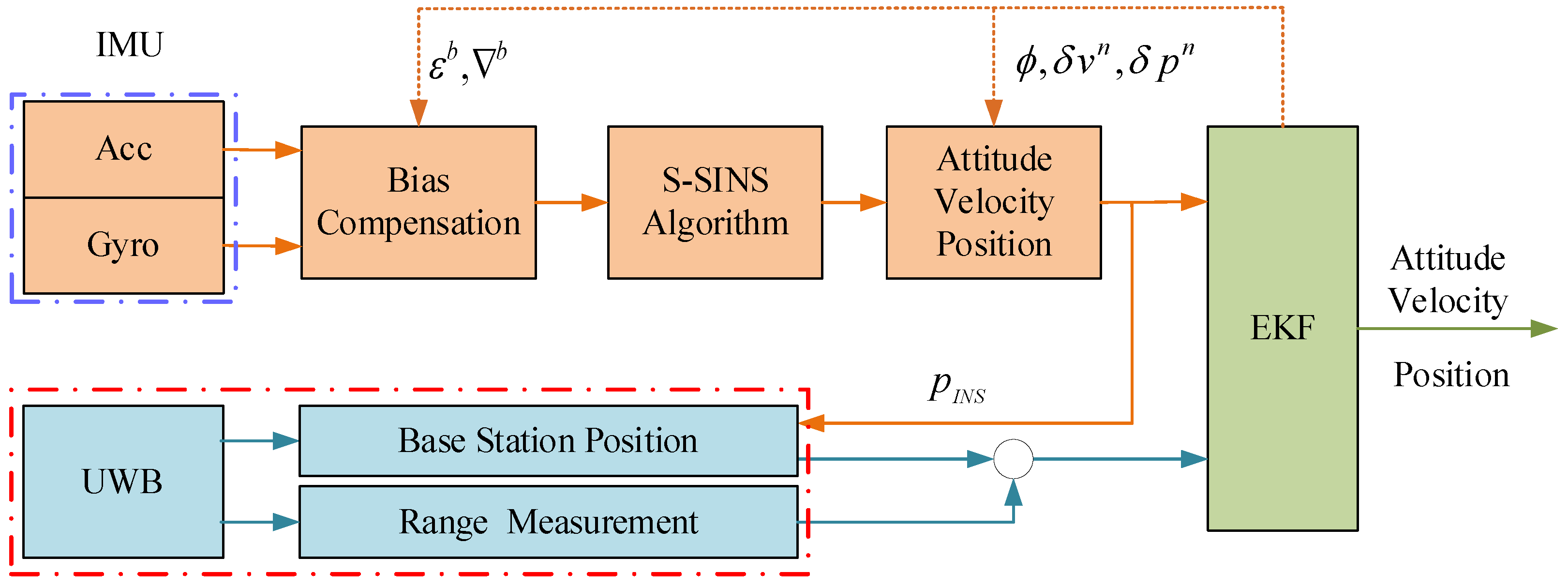
We integrate INS and UWB in a complementary manner to avert the imperfection of their independent operation. The data fusion of INS and UWB is usually performed by KF [36]. Taking LC as an example, the schematic of INS/UWB integrated navigation is drawn in Figure 1. In the INS/UWB LC system, the error propagation model of INS is taken as the state, and the difference between the position of INS and UWB output is taken as the observation, so the combined filter is constructed. During this period, navigation parameters (attitude, velocity and position) and inertial sensor parameters (stochastic error) need to be focused.
The time update process is:
X k = Φ k / k 1 X k 1 + Γ k / k 1 W k 1 P k / k 1 = Φ k / k 1 P k 1 Φ k / k 1 T + Γ k / k 1 Q k 1 Γ k / k 1 T
While the measurement update process is:
X ^ k = X ^ k / k 1 + K k Z k H k X ^ k / k 1 K k = P k / k 1 H k T H k P k / k 1 H k T + R k 1 P k = I K k H k P k / k 1
where X ^ k / k 1 is the state one-step prediction vector; P k / k 1 is the one-step prediction mean square error vector of X ^ k / k 1 . K k is filter gain.

2.2. Problem Formulation

For indoor low-cost and high-precision navigation and positioning, MEMS-based INS/UWB integrated systems with an LC-KF framework is restricted for the following reasons: (1) the inaccuracy of the INS error model; (2) filter divergence caused by the UWB outliers; (3) the poor robustness of the system during NLOS effect.
The first limitation arises from errors of the MEMS inertial sensors. In the INS/UWB integrated position system, the stochastic error of the inertial sensor, modeled as a first-order GM process in (2), is compensated by LC-KF. According to IEEE standards for inertial sensors [37], however, five main stochastic errors exist in inertial sensors, namely, Angular Random Walk (ARW), Quantization Noise (QN), Rate Random Walk (RRW), Bias Instability (BI) and Rate Ramp (RR), where RRW, BI and RR belong to CN. Consequently, it is obvious that the modeling method of inertial sensors mentioned above has shortcomings. On the basis of the KF theory, white noise (ARW) can be directly used as the driving noise of the system without modeling. QN can be transformed into equivalent white noise through the error model of INS, so it does not need to be modeled. In order to compensate for the drift of inertial sensors caused by CN in KF, it is essential to model the colored noise.
It is well known that the UWB tag outputs the location under the premise that at least four BTSs are available. For LC-KF architecture, however, when the number of available BSs is less than four, the performance of KF degrades over time, even resulting in filtering divergence.
Obviously, the conventional LC-KF integration scheme, in a complex indoor environment, is limited by the above-mentioned reasons. In order to provide a low-cost and high-precision MEMS-based INS/UWB indoor integrated navigation system, the following three main issues are covered in this paper, namely: (1) the application of tightly coupled (TC) architecture to accommodate fewer base stations; (2) the use of a novel INS error model to eliminate the effect of stochastic error on inertial sensors; (3) the improvement of navigation accuracy by enhancing the robustness of the system to the environment during the period of NLOS.

3. Methodology

An optimization-based MEMS-INS/UWB TC algorithm based on AV is proposed to improve the navigation performance of indoor UGV. The method is (1) based on Allan to improve the model of MEMS-based inertial sensors; (2) based on TC integration to mitigate the effect of fewer BSs; (3) an optimization-based EKF algorithm for suppressing the NLOS error of UWB.

3.1. Improving Error Model of INS

ϕ ˙ = C b n ( ε b + n w b + w Q b + w C b ) δ v ˙ n = C b n f b × ϕ + C b n ( b + n a b + f Q b + f C b ) δ p ˙ n = δ v n
where w Q b and f Q b , respectively, are the QN components in angular rate and specific force; w C b is a combination of RRW, BI and RR of angular rate, i.e., w C b = w B b + w K b + w R b ; similarly, f C b is a combination of RRW, BI and RR of angular rate, i.e., f C b = f B b + f K b + f R b .

3.1.1. On-Line Compensation of QN

w Q b and f Q b can be expressed, respectively, as
w Q b = δ α ˙ Q b f Q b = δ v ˙ Q b
where δ α Q b is the angular quantization noise of gyro, and δ v Q b is the velocity quantization noise of the acc.
Let us introduce a new formulated attitude error vector ϕ ˜ , and velocity error vector δ v ˜ n , as:
ϕ ˜ = ϕ + C b n δ α Q b δ v ˜ n = δ v n C b n δ v Q b
Applying (15) to (2), the error equation of INS enhanced by QN can be obtained:
ϕ ˜ ˙ = C b n ( ε b + n w b ) C b n w C b C b n w i b b × δ α Q b δ v ˜ ˙ n = C b n f b × ϕ ˜ + C b n ( b + n a b ) + C b n f C b   f n × C b n δ α Q b + C b n w i b b × δ v Q b δ p ˙ n = δ v ˜ n + C b n δ v Q b
In (16), QN is converted into white noise. It is obvious that δ α Q b related term is added to the attitude error equation, δ α Q b related term and δ v Q b related term are added to the velocity error equation.

3.1.2. On-Line Compensation of CN

AV is used to model the coexistence of three kinds of CN. The specific steps can be divided into: (1) the transfer function of the shaped filter of CN is obtained by introducing the spectral decomposition theorem; (2) given the transfer function of the shaping filter, the goal is to derive the stochastic differential equation of CN; (3) a unified equivalent differential equation is used to express three kinds of CN. A brief description is given here, and the details can be seen in [38].
Stochastic differential equations of BI:
y ˙ B ( t ) + β y B ( t ) = β B u B t
where u B t represents unit white Gaussian noise.
Stochastic differential equations of RRW:
y ˙ K ( t ) = K u K t
where u K t represents unit white Gaussian noise.
Stochastic differential equations of RR:
y ¨ R ( t ) + 2 w 0 y ˙ R ( t ) + w 0 y R ( t ) = R u R t
where u R t represents unit white Gaussian noise.
The equivalent model of BI, RRW and RR:
y 4 + a 3 y 3 + a 2 y 2 + a 1 y ˙ + a 0 y = b 3 u 3 + b 2 u 2 + b 1 u ˙ + b 0 u
The state-space form of (20) can be expressed as
x ˙ i t = A i x i t + B i u i t
y i t = C i x i t
with
A = 0 0 0 a 0 1 0 0 a 1 0 1 0 a 2 0 0 1 a 3 , B = b 0 b 1 b 2 b 3 , C = 0 0 0 1 T
where x i   i = 1 , 2 , 3 , 4 denotes the state vector.

3.2. INS/UWB TC-EKF Model Design

The main difference from the LC-KF model in Section 2 is that the measurement in TC positioning is the difference stemming from the distance calculated by the INS and the position of each BS and the measured distance of the UWB. In Figure 2, the framework of the INS/UWB positioning system based on TC is presented.

3.2.1. Error-State Equation

The system model for INS/UWB TC-EKF integration can be represented as follows:
X ˙ t = F t X t + G t W t + W Q t + W C t
with
W Q t = F 11 F 21 F 31 F 41 F 51
F 11 = C b n w i b b × δ α Q b F 21 = f n × C b n δ α Q b + C b n w i b b × δ v Q b F 31 = C b n δ v Q b F 41 = 0 F 51 = 0
W C t = H A w C b f C b 0 0 0 , H A = d i a g C b n C b n 0 0 0
where W Q t is the equivalent white noise after the conversion of QN, and W C t is colored noise. w C b and f C b are defined as:
w C b = y 1 y 2 y 3 T , f C b = y 4 y 5 y 6 T
where y i i = 1 , 2 , , 6 satisfies (22). Combining (22) and (28), W C t can be rewritten as
W C t = H A H B x 1 x 2 x 6
where
H B = d i a g C 1 , , C 6
Therefore, the state-space of W C t is described as:
x ˙ i t = F y y x i t + u y t
W C t = F x y x t
where F x y = d i a g ( A 1 , , A 6 ) , u y t = B 1 u 1 t B 6 u 6 t T , F x y = H A H B .
The process noise covariance matrix Q C of (31) satisfies:
E u y t u y t τ T = Q y δ τ
List x i = x 1 , x 2 , , x 6 T as a new state variable. Then (24) can be rephrased as
x ˙ t x ˙ t = F x x F x y 0 F y y x t x t + W Q t t u y t
The process noise covariance matrix Q C of (34) satisfies:
E W Q t t u y t W Q t t u y t T = Q δ τ

3.2.2. Measurement Equation

It is assumed that N available UWB BSs are set, the difference between the position is determined by INS and the distance measured by UWB is
z i = p A i n p I N S n r i , i = 1 , 2 , , N
where p A i n = x A i , y A i , z A i is the coordinate of the UWB BS in n-frame. p I N S n = x I N S , y I N S , z I N S is the position estimated by INS. r i represents the distance between the tag and the i t h base station.
The measurement of the system is selected as:
z = z 1 z 2 z N T
The measurement equation is:
z k = f x k + v k
with
f x k = x A i x I N S , k 2 + y A i y I N S , k 2 + z A i z I N S , k 2 r i
where v k is measurement noise, that is, UWB distance measurement noise. The positioning error of INS is:
x I N S , k = x k + 1 + δ x k + 1 , y I N S , k = y k + 1 + δ y k + 1 , z I N S , k = z k + 1 + δ z k + 1
Substituting (40) to (38), then, the Taylor series expansion is carried out at 0 , 0 , 0 to obtain the linearized measurement equation.
z k = H k x k + v k
with
H k = 0 N × 3 J 0 , 0 , 0 0 N × 3 0 N × 3 0 N × 3
where J 0 , 0 , 0 represents the Jacobian matrix of (41) at 0 , 0 , 0 .
J 0 , 0 , 0 = x I N S , k x A 1 p A 1 n p I N S n y I N S , k y A 1 p A 1 n p I N S n z I N S , k z A 1 p A 1 n p I N S n x I N S , k x A 2 p A 2 n p I N S n x I N S , k x A 2 p A 2 n p I N S n x I N S , k x A 2 p A 2 n p I N S n x I N S , k x A N p A N n p I N S n x I N S , k x A N p A N n p I N S n x I N S , k x A N p A N n p I N S n

3.3. MAEKF Based on the Dynamic Weight Function for UWB NLOS

In the EKF algorithm, the noise characteristics, including the system noise and measurement noise, are subordinated to the Gaussian distribution. However, the state estimation will be interfered when the system is suffering from NLOS. To assess the impact of NLOS on the current position, an optimization-based EKF algorithm is proposed which can use the probability density function based on the Gaussian distribution to adjust the noise adaptively.
Let’s introduce a NLOS discrimination index D I as
D I = p A , k n p I N S , k n r k
with
r k = r ¯ k + Δ r k + v r k ,
where p A , k n is the k t h coordinate of the BS; and p I N S , k n denotes the k t h position estimated by INS; r ¯ k denotes the veritable distance from the tag to the BS; Δ r is defined as the systematic error term, such as NLOS error; v r k is the ranging error.
It is considered that p I N S , k n is not affected by the NLOS and the base station coordinates are fixed. Accordingly, it indicates that the UWB signal is interfered by NLOS during transmission under the condition that the value of D I is too small. Assuming D I satisfies a Gaussian distribution with a mean of 0 and a variance of σ D I 2 , i.e., D I 0 , σ D I 2 . Consequently, the probability density function of D I can be used to evaluate the degree to which the current UWB signal is affected by the NLOS, as shown in (46).
p = 0 D I 2 σ D I 2 π e x 2 2 σ D I 2 d x
Therefore, the dynamic weight function is designed in the following form:
S ( p i ) = 1 + p i , p i t h 1 , p i < t h
where t h denotes the threshold, determined by the empirical value.
Based on (47), the adaptive measurement noise is expressed as:
R k = R 0 S ( p i )
In summary, the framework of the proposed method in this paper is presented in Figure 3.

4. Experimental Test and Analysis

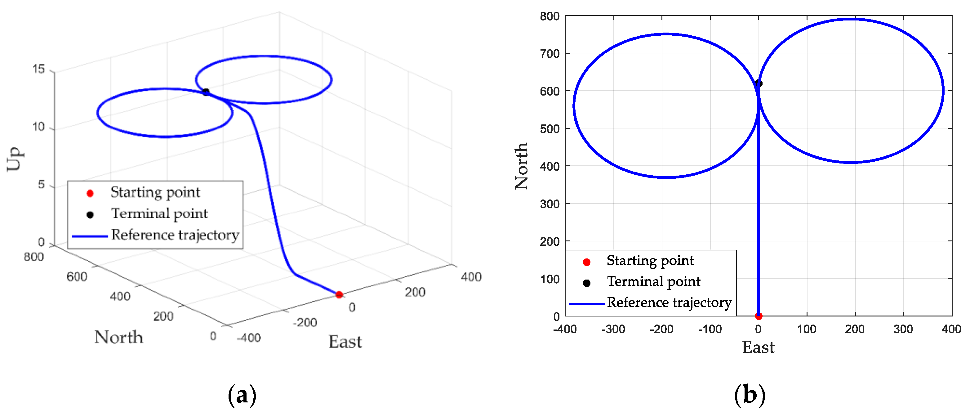
In order to validate the availability and superiority of the proposed algorithm in the MEMS-Based INS/UWB integrated positioning system, ground vehicle experiments were carried out. In the experiment, the independently developed MEMS-based INS/UWB integrated position system and reference integrated navigation system with high accuracy are included. Sensor parameter configurations in the MEMS-Based INS/UWB integrated navigation system are described in Table 1. The intention of the high-precision reference integrated navigation system is to furnish the high-precision reference of navigation information for the MEMS-Based INS/UWB integrated navigation system. It is composed of LCI-1 strategic IMU, Propak satellite receiver and two GNSS antennas. The accuracy of attitude, velocity and position provided by the high-precision reference integrated navigation system are 0.01°, 0.05 m/s and 0.1 m, respectively. The trajectory of the vehicle in the experiment is shown in Figure 4.
Two experimental schemes were designed to analyze the performance of the proposed algorithm under different conditions. The proposed algorithm was also compared with the existing EKF method and AEKF method. The details of the experimental schemes are as follows:
(1) The experiment was conducting where UWB signal is good. This allows normal measurement of UWB. This can ensure the normal and effective operation of various navigation sensors. The whole process lasted for 166 s.
(2) We actively and intermittently blocked the UWB signal in some time periods in order to simulate a possible NLOS situation. In this way, INS can be measured normally, while UWB may have poor navigation and positioning performance or even abnormal measurement information. The whole process lasted 166 s.

4.1. Performance Comparison of Different Methods for Good UWB Signal

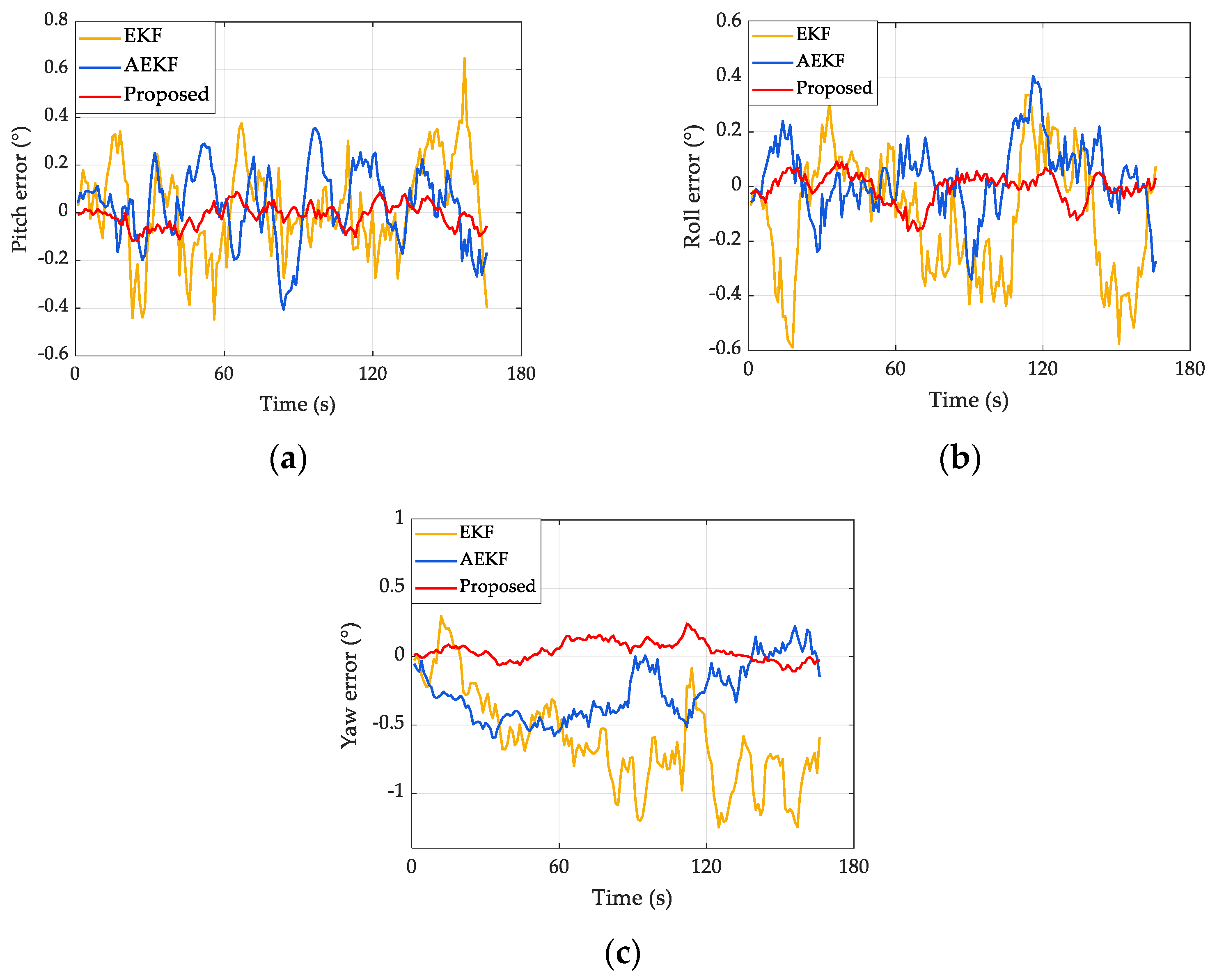
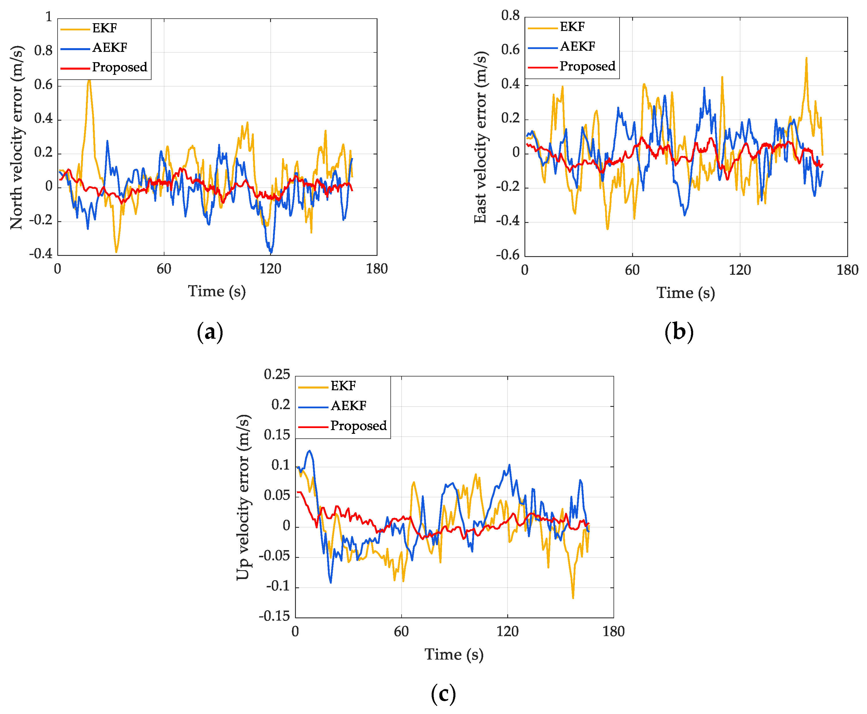
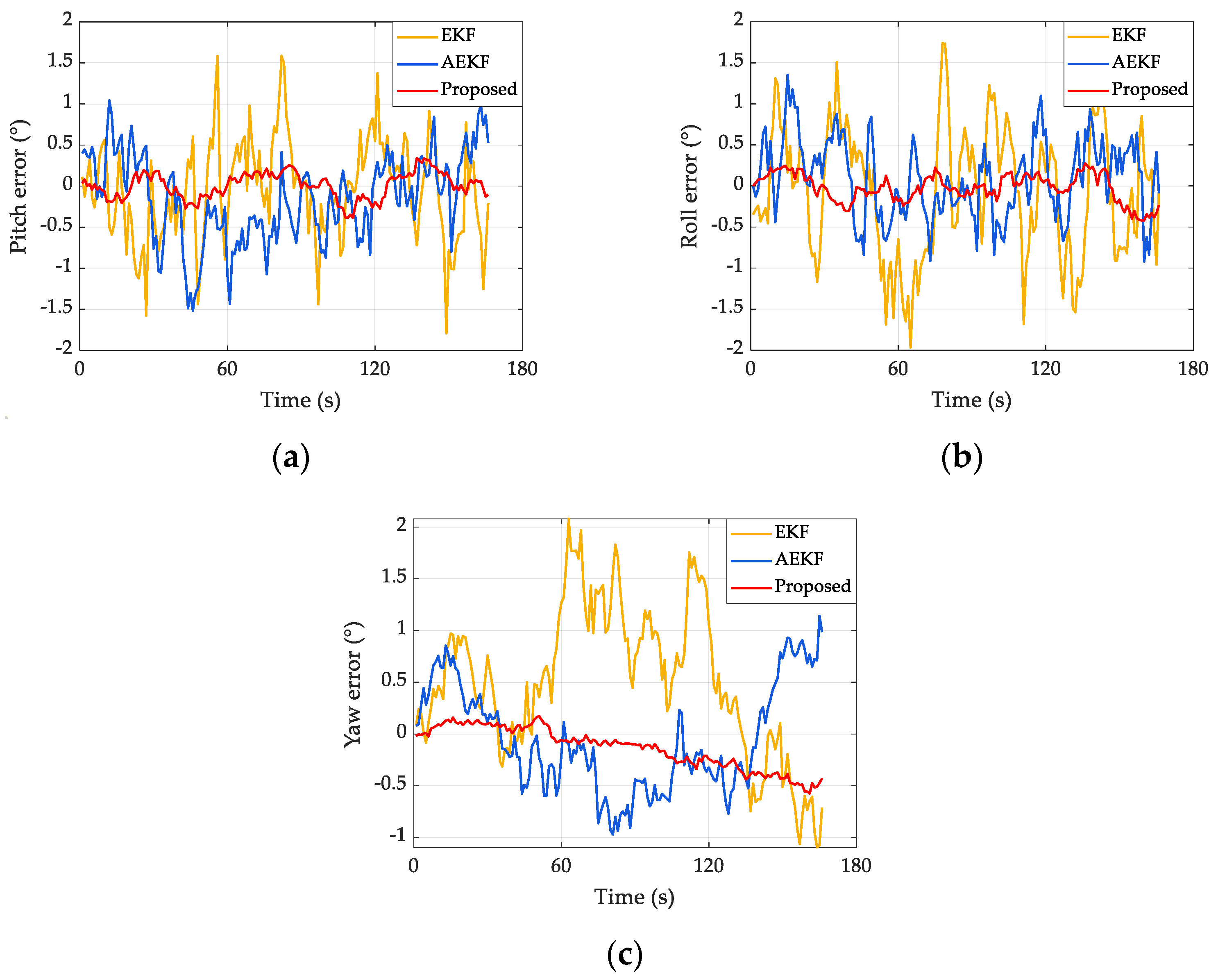
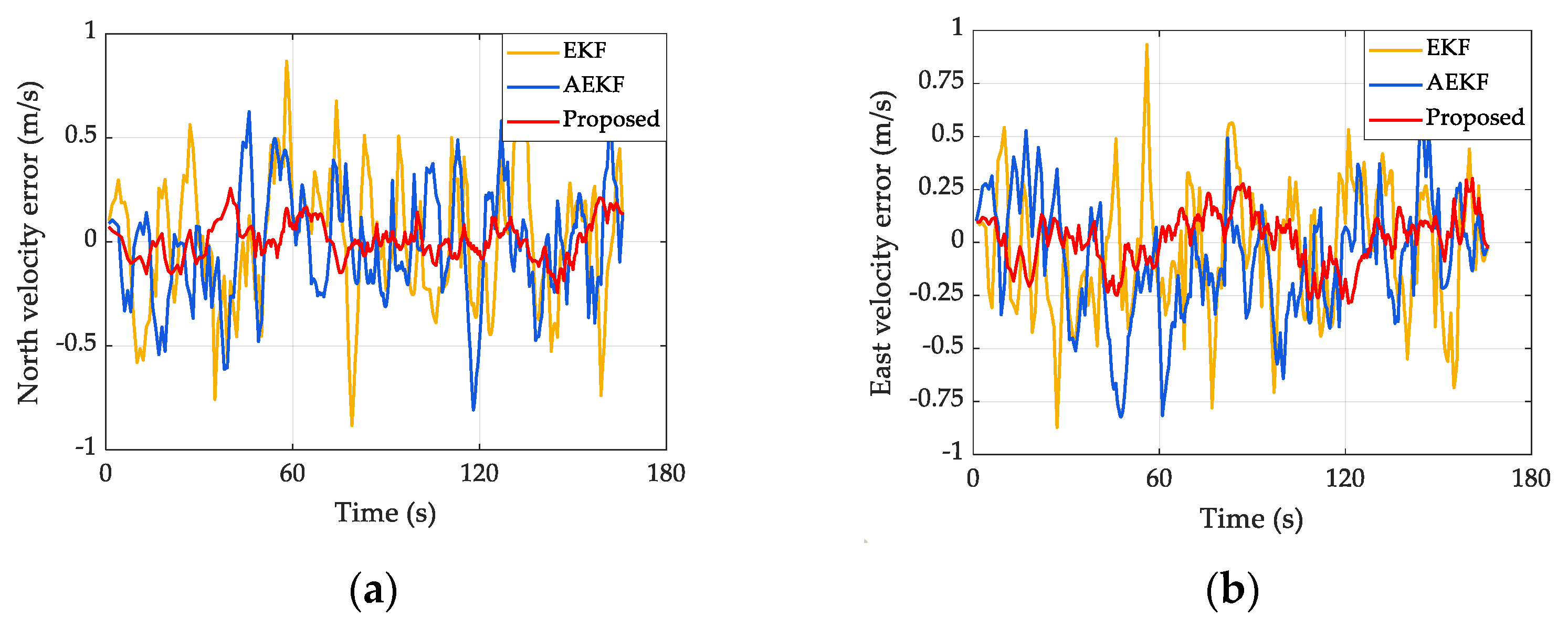
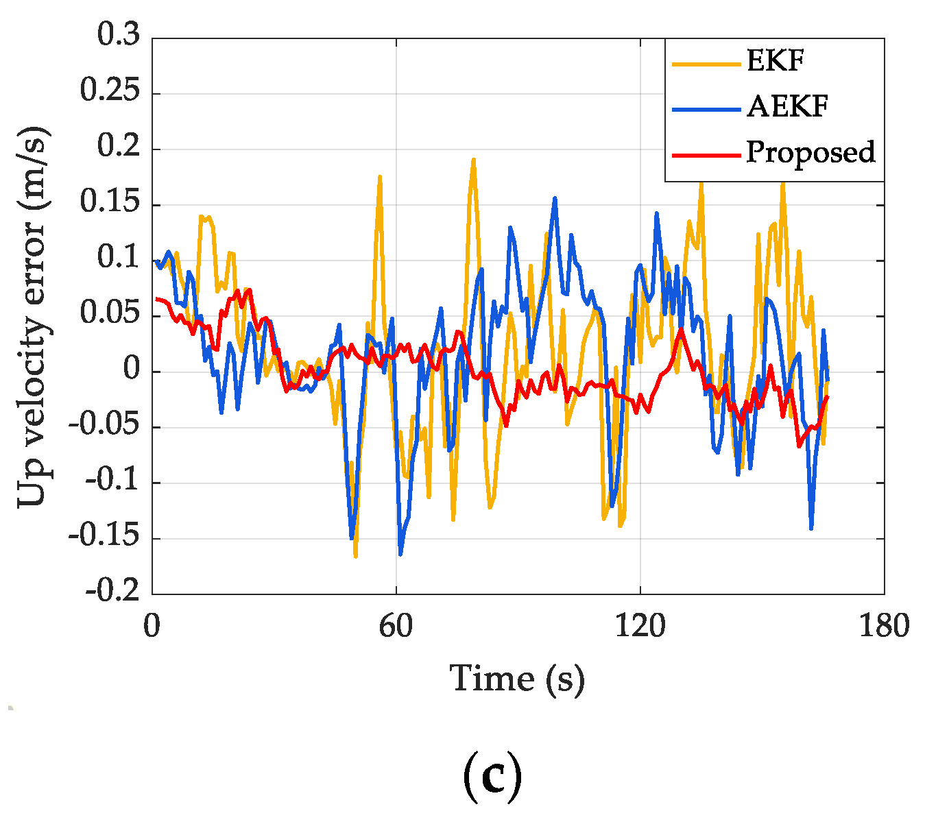
This test was conducted according to the first experimental scheme. Figure 5, Figure 6 and Figure 7 compare errors of attitude, velocity and position of the proposed algorithm with the other two algorithms. The yellow, blue and red lines correspond to the EKF method, the AEKF method and the proposed method, respectively. It can be observed that the fluctuation of the red line is the smallest compared to the yellow and blue lines, meaning that errors obtained by the proposed method in this paper are smaller than those by the EKF and AEKF method.
The root mean square error (RMSE) of errors of navigation information (attitude, velocity, position) of three-axes under different algorithms are listed in Table 2. RMSE is defined as:
R M S E = 1 N i = 1 N x i x ^ i 2
where N represents the total number of samples, x i represents the navigation parameters provided by INS/UWB integrated navigation system at time i , x ^ i represents i t h the navigation parameters provided by the reference system. The purpose of RMSE is to weigh the deviation between the measured value and real value. The smaller the RMSE, the higher the measurement accuracy.
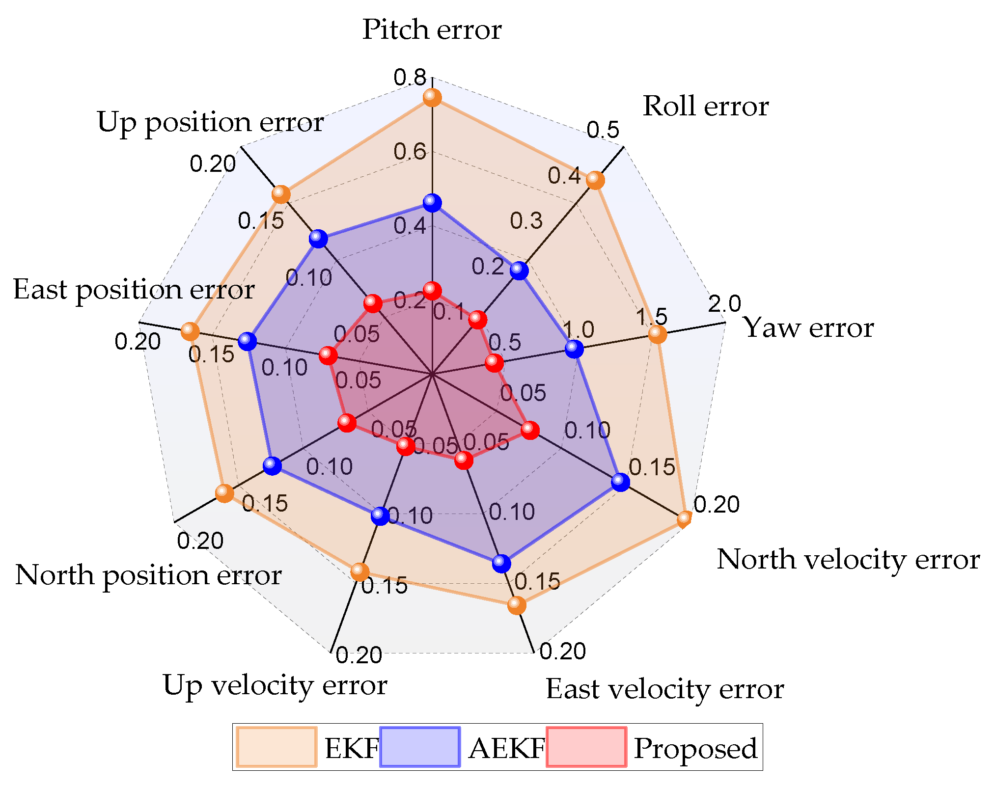
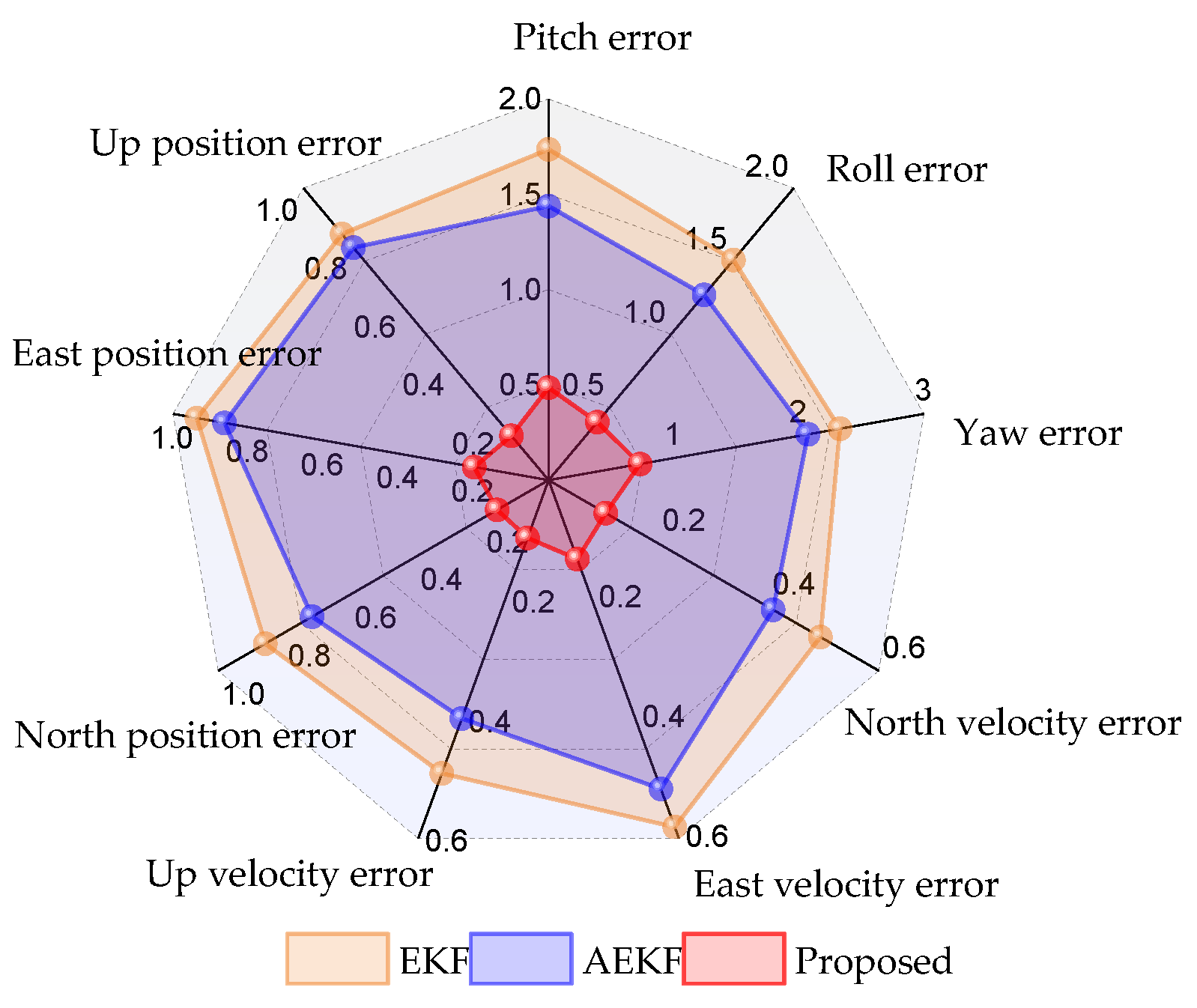
In order to compare the navigation performance of the proposed algorithm with the other two methods more clearly and intuitively in the first scheme, the radar map of navigation parameter error statistics (RMSE) of the three methods are shown in Figure 8.
From the analysis of above error results, it can be observed that the proposed algorithm and AEKF improve the accuracy of the MEMS-based INS/UWB integrated navigation system over the EKF method. Similarly, the proposed algorithm produces obvious improvement in terms of the accuracy of attitude, velocity and position compared with the existing AEKF method. According to Table 2, the proposed method can obtain better error suppression effect. Compared with the EKF algorithm, the proposed method reduces the RMSE error in attitude, velocity and position from 0.745°, 0.426°, 1.536°; 0.166 m/s, 0.197 m/s, 0.142 m/s; and 0.161 m, 0.165 m, 0.158 m to 0.224°, 0.119°, 0.424°; 0.062 m/s, 0.076 m/s, 0.052 m/s; and 0.066 m, 0.071 m, 0.062 m, respectively, indicating a significant accuracy improvement by 69%, 72%, 72%, 62%, 61%, 63%, 59%, 56% and 60%, respectively. Compared with the existing AEKF method, the proposed method improved attitude accuracy by over 47% and positioning accuracy by over 45%. The reason is that the traditional EKF and AEKF are significantly affected by the stochastic error of inertial sensors. The proposed method uses AV to establish a more accurate INS error model, which suppresses the stochastic error increase of the inertial sensors during the time update stage of filtering. Therefore, its estimation performance is superior to traditional EKF and AEKF. It can also be seen from Figure 8 that the navigation performance of the proposed method is generally better than that of AEKF and EKF in a good navigation environment.

4.2. Performance Comparison of Different Methods for UWB NLOS

This test was performed by applying the second experimental scheme. In scheme 2, the measurement of UWB will be abnormal due to human interference. Figure 9, Figure 10 and Figure 11, respectively, show errors of attitude, velocity and position of the proposed algorithm and the other two methods when the UWB undergoes NLOS. In addition, the corresponding RMSE under three methods is listed in Table 3. The radar map of the navigation parameter error statistical data (RMSE) of the three methods is plotted as Figure 12.
By analyzing Figure 9, Figure 10 and Figure 11 and Table 3, we evaluated the performance of the proposed algorithm and other two methods. When affected by NLOS, the performance of the MEMS-based INS/UWB integrated system based on traditional EKF mainly relies on INS for navigation. Due to the significant impact of stochastic errors of inertial sensor, the performance of EKF degrades quickly. It can be observed from Table 3 that the proposed method reduces RMSE errors in attitude, velocity and position more than 72%, 77% and 78%, respectively, compared to the EKF method. It indicates that the proposed method outperforms the EKF method. Table 3 also shows that attitude accuracy is improved by more than 60% and position accuracy is improved by more than 70% compared with the existing AEKF method. The reason is that the proposed method designed a dynamic weight function, which can effectively solve the impact of NLOS on the AEKF method. Moreover, the proposed method suppresses the influence of stochastic noise from inertial sensor during the AEKF time update stage by using AV to assist in the establishment of the INS error model. As a result, the proposed method outperforms the AEKF method. It can also be clearly seen from Figure 12 that the proposed method has better navigation performance than AEKF and EKF.
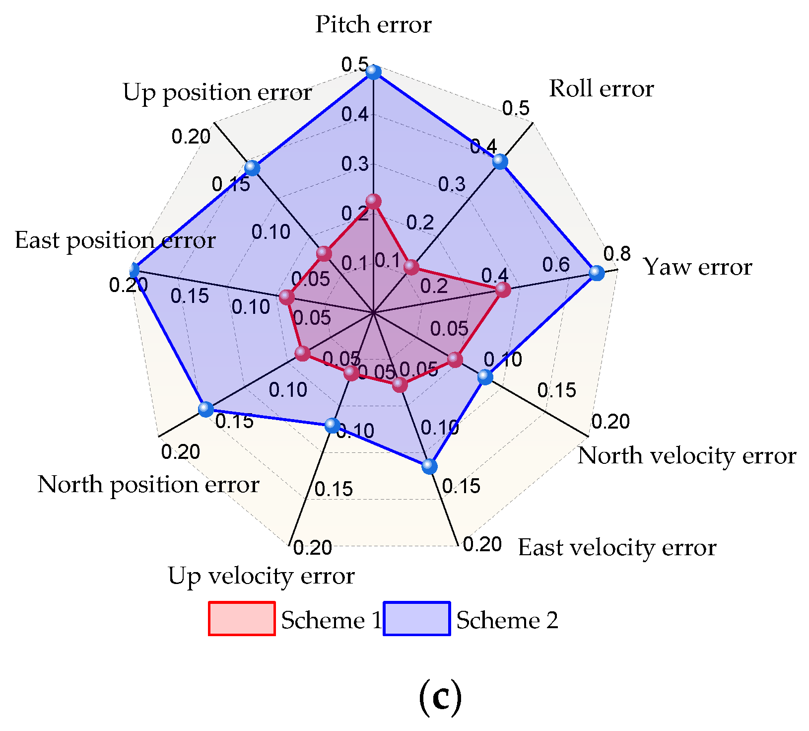
Further, the navigation performance of EKF, AEKF and the proposed method under different test schemes is compared, as shown in Figure 13.
It can be clearly seen from Figure 13 that when the vehicle experiment is conducted from the first scheme to the second scheme, that is, the normal operation of each sensor changes to the abnormal output of some sensors, the navigation performance of the EKF method decreases most significantly. The navigation performance of AEKF method has also decreased, and the error has increased significantly, which indicates that the NLOS error has a great impact on the navigation accuracy of AEKF. However, the proposed method can still achieve better navigation performance under such conditions.

5. Conclusions

In this paper, an improved navigation method, Allan variance (AV) to assist a modified adaptive extended Kalman Filter based on the dynamic weight function (DWF-MAEFF), is proposed to further enhance the performance of MEMS-based INS/UWB integrated systems. A better INS errors model is obtained by using AV to model stochastic errors of inertial sensors. In addition, the MAEKF algorithm is proposed to design the dynamic weight function, which can adjust the weight of measurement noise reasonably and dynamically in order to further enhance and improve the robustness of the AEKF algorithm. The experimental results showed that the proposed method can improve the positioning accuracy by more than 60% compared with existing integrated navigation methods based on EKF and AEKF. In future work, we will integrate GNSS into the INS/UWB fusion scheme to achieve seamless positioning of UGVs.

Author Contributions

J.M. conducted the research and revised the manuscript. X.H. was responsible for collection of data and creating figures. Q.W. revised and improved the manuscript. All authors have read and agreed to the published version of the manuscript.

Funding

This work was supported by the projects of the National Key Research and Development Plan of China (No. 2020YFB1600703).

Data Availability Statement

The datasets used and/or analyzed during the current study are available from the corresponding author on reasonable request.

Conflicts of Interest

The authors declare no conflict of interest.

References

  1. Li, J.; He, J. Localization and Mapping for UGV in Dynamic Scenes with Dynamic Objects Eliminated. Machines 2022, 10, 1044. [Google Scholar] [CrossRef]
  2. Wei, X.; Li, J.; Han, D.; Wang, J.; Zhan, Y.; Wang, X.; Feng, K. An In-Flight Alignment Method for Global Positioning System-Assisted Low Cost Strapdown Inertial Navigation System in Flight Body with Short-Endurance and High-Speed Rotation. Remote Sens. 2023, 15, 711. [Google Scholar] [CrossRef]
  3. Cheng, Y.; Zhou, T. UWB indoor positioning algorithm based on TDOA technology. In Proceedings of the 2019 10th International Conference on Information Technology in Medicine and Education (ITME), Qingdao, China, 23 August 2019; pp. 777–782. [Google Scholar]
  4. Poulose, A.; Eyobu, O.S.; Kim, M.; Han, D.S. Localization error analysis of indoor positioning system based on UWB measurements. In Proceedings of the 2019 Eleventh International Conference on Ubiquitous and Future Networks (ICUFN), Croatia Spain, 2–5 July 2019; pp. 84–88. [Google Scholar]
  5. Zasowski, T.; Althaus, F.; Stager, M.; Wittneben, A.; Troster, G. UWB for noninvasive wireless body area networks: Channel measurements and results. In Proceedings of the IEEE Conference on Ultra Wideband Systems and Technologies, Reston, VA, USA, 16–19 November 2003; pp. 285–289. [Google Scholar]
  6. Meissner, P.; Leitinger, E.; Witrisal, K. UWB for robust indoor tracking: Weighting of multipath components for efficient estimation. IEEE Wirel. Commun. Lett. 2014, 3, 501–504. [Google Scholar] [CrossRef]
  7. Feng, D.; Wang, C.; He, C.; Zhuang, Y.; Xia, X.-G. Kalman-filter-based integration of IMU and UWB for high-accuracy indoor positioning and navigation. IEEE Internet Things J. 2020, 7, 3133–3146. [Google Scholar] [CrossRef]
  8. Liu, J.; Pu, J.; Sun, L.; He, Z. An approach to robust INS/UWB integrated positioning for autonomous indoor mobile robots. Sensors 2019, 19, 950. [Google Scholar] [CrossRef]
  9. Liu, C.; Kadja, T.; Chodavarapu, V.P. Experimental Evaluation of Sensor Fusion of Low-Cost UWB and IMU for Localization under Indoor Dynamic Testing Conditions. Sensors 2022, 22, 8156. [Google Scholar] [CrossRef]
  10. Dong, X.; Gao, Y.; Guo, J.; Zuo, S.; Xiang, J.; Li, D.; Tu, Z. An Integrated UWB-IMU-Vision Framework for Autonomous Approaching and Landing of UAVs. Aerospace 2022, 9, 797. [Google Scholar] [CrossRef]
  11. Huang, W.; Wen, D.; Geng, J.; Zheng, N.-N. Task-specific performance evaluation of UGVs: Case studies at the IVFC. IEEE Trans. Intell. Transp. Syst. 2014, 15, 1969–1979. [Google Scholar] [CrossRef]
  12. Gao, Y.; Chang, D.; Fang, T.; Luo, T. Design and optimization of parking lot in an underground container logistics system. Comput. Ind. Eng. 2019, 130, 327–337. [Google Scholar] [CrossRef]
  13. Szrek, J.; Zimroz, R.; Wodecki, J.; Michalak, A.; Góralczyk, M.; Worsa-Kozak, M. Application of the infrared thermography and unmanned ground vehicle for rescue action support in underground mine—The amicos project. Remote Sens. 2020, 13, 69. [Google Scholar] [CrossRef]
  14. Hol, J.D.; Dijkstra, F.; Luinge, H.; Schon, T.B. Tightly coupled UWB/IMU pose estimation. In Proceedings of the 2009 IEEE International Conference on Ultra-Wideband, Vancouver, BC, Canada, 9–11 September 2009; pp. 688–692. [Google Scholar]
  15. Hol, J.D. Sensor Fusion and Calibration of Inertial Sensors, Vision, Ultra-Wideband and GPS; Linköping University Electronic Press: Linköping, Sweden, 2011; p. 143. [Google Scholar]
  16. Wen, K.; Yu, K.; Li, Y.; Zhang, S.; Zhang, W. A new quaternion Kalman filter based foot-mounted IMU and UWB tightly-coupled method for indoor pedestrian navigation. IEEE Trans. Veh. Technol. 2020, 69, 4340–4352. [Google Scholar] [CrossRef]
  17. Godha, S.; Cannon, M. GPS/MEMS INS integrated system for navigation in urban areas. Gps. Solut. 2007, 11, 193–203. [Google Scholar] [CrossRef]
  18. Petkov, P.; Slavov, T. Stochastic modeling of MEMS inertial sensors. Cybern. Inf. Technol. 2010, 10, 31–40. [Google Scholar]
  19. Gomaa, W.; Elbasiony, R.; Ashry, S. Adl classification based on autocorrelation function of inertial signals. In Proceedings of the 2017 16th IEEE International Conference on Machine Learning and Applications (ICMLA), Cancun, Mexico, 18–21 December 2017; pp. 833–837. [Google Scholar]
  20. Jain, R.; Semwal, V.B.; Kaushik, P. Stride segmentation of inertial sensor data using statistical methods for different walking activities. Robotica 2022, 40, 2567–2580. [Google Scholar] [CrossRef]
  21. Huang, L. Auto regressive moving average (ARMA) modeling method for Gyro random noise using a robust Kalman filter. Sensors 2015, 15, 25277–25286. [Google Scholar] [CrossRef]
  22. El-Sheimy, N.; Hou, H.; Niu, X. Analysis and modeling of inertial sensors using Allan variance. IEEE Trans. Instrum. Meas. 2007, 57, 140–149. [Google Scholar] [CrossRef]
  23. Kulikov, R.; Chugunov, A.; Pudlovskiy, V.; Tsaregorodtsev, D. Weighted pseudo-range method of positioning in local ultra-wide band navigation systems. In Proceedings of the 2019 Ural Symposium on Biomedical Engineering, Radioelectronics and Information Technology (USBEREIT), Yekaterinburg, Russia, 13–14 May 2021; pp. 387–390. [Google Scholar]
  24. Zheng, S.; Li, Z.; Liu, Y.; Zhang, H.; Zou, X. An optimization-based UWB-IMU fusion framework for UGV. IEEE Sens. J. 2022, 22, 4369–4377. [Google Scholar] [CrossRef]
  25. Yang, X.; Wang, J.; Song, D.; Feng, B.; Ye, H. A novel NLOS error compensation method based IMU for UWB indoor positioning system. IEEE Sens. J. 2021, 21, 11203–11212. [Google Scholar] [CrossRef]
  26. Wu, F.; Liu, Z. Research on uwb/imu fusion positioning technology in mine. In Proceedings of the 2020 International Conference on Intelligent Transportation, Big Data & Smart City (ICITBS), Vientiane, Laos, 11–12 January 2020; pp. 934–937. [Google Scholar]
  27. Zeng, Z.; Liu, S.; Wang, L. UWB/IMU integration approach with NLOS identification and mitigation. In Proceedings of the 2018 52nd Annual Conference on Information Sciences and Systems (CISS), Princeton, NJ, USA, 21–23 March 2018; pp. 1–6. [Google Scholar]
  28. Li, Z.; Wang, R.; Gao, J.; Wang, J. An approach to improve the positioning performance of GPS/INS/UWB integrated system with two-step filter. Remote Sens. 2017, 10, 19. [Google Scholar] [CrossRef]
  29. Fakoorian, S.; Mohammadi, A.; Azimi, V.; Simon, D. Robust Kalman-type filter for non-Gaussian noise: Performance analysis with unknown noise covariances. J. Dyn. Syst. Meas. Control 2019, 141, 091011. [Google Scholar] [CrossRef]
  30. Jiancheng, F.; Sheng, Y. Study on innovation adaptive EKF for in-flight alignment of airborne POS. IEEE Trans. Instrum. Meas. 2011, 60, 1378–1388. [Google Scholar] [CrossRef]
  31. Hanlon, P.D.; Maybeck, P.S. Multiple-model adaptive estimation using a residual correlation Kalman filter bank. IEEE Trans. Aerosp. Electron. Syst. 2000, 36, 393–406. [Google Scholar] [CrossRef]
  32. Panich, S.; Afzulpurkar, N. Mobile robot integrated with gyroscope by using IKF. Int. J. Adv. Robot. Syst. 2011, 8, 22. [Google Scholar] [CrossRef]
  33. Karasalo, M.; Hu, X. An optimization approach to adaptive Kalman filtering. Automatica 2011, 47, 1785–1793. [Google Scholar] [CrossRef]
  34. Qiao, S.; Fan, Y.; Wang, G.; Mu, D.; He, Z. Radar Target Tracking for Unmanned Surface Vehicle Based on Square Root Sage–Husa Adaptive Robust Kalman Filter. Sensors 2022, 22, 2924. [Google Scholar] [CrossRef]
  35. Narasimhappa, M.; Mahindrakar, A.D.; Guizilini, V.C.; Terra, M.H.; Sabat, S.L. MEMS-based IMU drift minimization: Sage Husa adaptive robust Kalman filtering. IEEE Sens. J. 2019, 20, 250–260. [Google Scholar] [CrossRef]
  36. Fan, Q.; Sun, B.; Sun, Y.; Zhuang, X. Performance enhancement of MEMS-based INS/UWB integration for indoor navigation 543 applications. IEEE Sens. J. 2017, 17, 3116–3130. [Google Scholar] [CrossRef]
  37. Curey, R.K.; Ash, M.E.; Thielman, L.O.; Barker, C.H. Proposed IEEE inertial systems terminology standard and other inertial 545 sensor standards. In Proceedings of the PLANS 2004. Position Location and Navigation Symposium (IEEE Cat. No. 546 04CH37556), Hachioji, Japan, 23–24 March 2004; pp. 83–90. [Google Scholar]
  38. Han, S.; Wang, J. Quantization and Colored Noises Error Modeling for Inertial Sensors for GPS/INS Integration. IEEE Sens. J. 2011, 11, 1493–1503. [Google Scholar] [CrossRef]
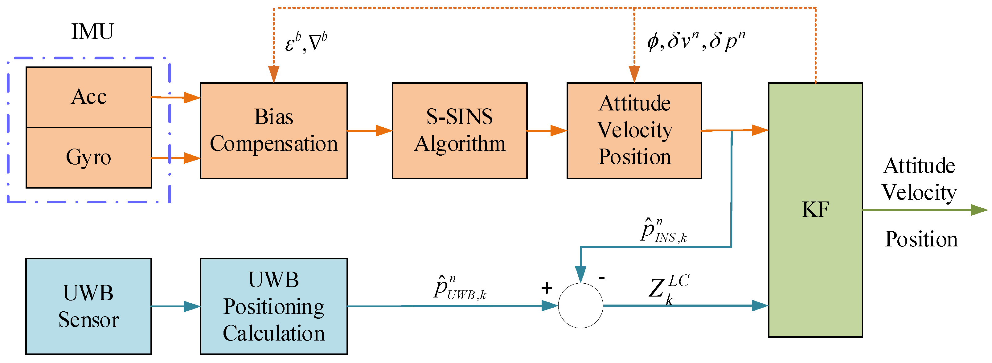
Figure 1. The framework of INS/UWB positioning system based on LC.
Remotesensing 15 02535 g001
Figure 2. The framework of the INS/UWB positioning system based on TC.
Remotesensing 15 02535 g002
Figure 3. The flowchart of the proposed method.
Remotesensing 15 02535 g003
Figure 4. Experiment trajectory. (a) Three-dimensional trajectory of vehicle movement; (b) Two-dimensional trajectory of vehicle movement.
Remotesensing 15 02535 g004
Figure 5. Attitude errors of three algorithms in scheme 1. (a) Comparison of Pitch error of three algorithms; (b) Comparison of Roll error of three algorithms; (c) Comparison of Yaw error of three algorithms.
Remotesensing 15 02535 g005
Figure 6. Velocity errors of three algorithms in scheme 1. (a) Comparison of north velocity error of three algorithms; (b) Comparison of east velocity error of three algorithms; (c) Comparison of up velocity error of three algorithms.
Remotesensing 15 02535 g006
Figure 7. Position errors of three algorithms in scheme 1. (a) Comparison of north position error of three algorithms; (b) Comparison of east position error of three algorithms; (c) Comparison of up position error of three algorithms.
Remotesensing 15 02535 g007
Figure 8. The radar map of RMSE of navigation parameter errors in scheme 1.
Remotesensing 15 02535 g008
Figure 9. Attitude errors of three algorithms in scheme 2. (a) Comparison of Pitch error of three algorithms; (b) Comparison of Roll error of three algorithms; (c) Comparison of Yaw error of three algorithms.
Remotesensing 15 02535 g009
Figure 10. Velocity errors of three algorithms in scheme 2. (a) Comparison of north velocity error of three algorithms; (b) Comparison of east velocity error of three algorithms; (c) Comparison of up velocity error of three algorithms.
Remotesensing 15 02535 g010aRemotesensing 15 02535 g010b
Figure 11. Position errors of three algorithms in scheme 2. (a) Comparison of north position error of three algorithms; (b) Comparison of east position error of three algorithms; (c) Comparison of up position error of three algorithms.
Remotesensing 15 02535 g011
Figure 12. The radar map of RMSE of navigation parameter errors in scheme 2.
Remotesensing 15 02535 g012
Figure 13. The RMSE of navigation parameter errors of three algorithms in two schemes. (a) The RMSE of navigation parameter errors of EKF in two schemes; (b) The RMSE of navigation parameter errors of AEKF under in schemes; (c) The RMSE of navigation parameter errors of the proposed algorithm in two schemes.
Remotesensing 15 02535 g013aRemotesensing 15 02535 g013b
Table 1. Relevant parameter information of sensors.
SensorParameter
RangeConstant DriftsRandom Walk
gyro ± 350 10 deg / h 0.3 deg / h
acc ± 10   g 5   mg 90   μ g / Hz
Table 2. The RMSE of navigation error in test scheme 1.
MethodAttitude Error (°)Velocity Error (m/s)Position Error (m)
PitchRollYawEastNorthUpEastNorthUp
EKF0.7450.4261.5360.1660.1970.1420.1610.1650.158
AEKF0.4610.2270.9680.1360.1460.1020.1240.1260.119
Proposed0.2240.1190.4240.0620.0760.0520.0660.0710.062
Table 3. The RMSE of navigation error in test scheme 2.
MethodAttitude Error (°)Velocity Error (m/s)Position Error (m)
PitchRollYawEastNorthUpEastNorthUp
EKF1.7631.5082.3290.5810.4940.4910.9370.8580.843
AEKF1.4381.2692.0730.5170.4080.3990.8630.7160.796
Proposed0.4850.3970.7310.1320.1040.0970.1980.1560.152
Disclaimer/Publisher’s Note: The statements, opinions and data contained in all publications are solely those of the individual author(s) and contributor(s) and not of MDPI and/or the editor(s). MDPI and/or the editor(s) disclaim responsibility for any injury to people or property resulting from any ideas, methods, instructions or products referred to in the content.