
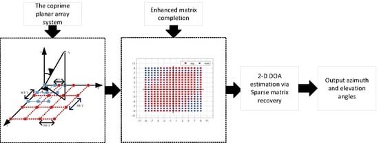
Sparsity-Based Two-Dimensional DOA Estimation for Co-Prime Planar Array via Enhanced Matrix Completion

National Lab of Radar Signal Processing, Xidian University, Xi’an 710071, China
*
Author to whom correspondence should be addressed.
Remote Sens. 2022, 14(19), 4690; https://doi.org/10.3390/rs14194690
Submission received: 26 August 2022
/
Accepted: 15 September 2022
/
Published: 20 September 2022
(This article belongs to the Special Issue Radar High-Speed Target Detection, Tracking, Imaging and Recognition)
Abstract
:In this paper, the two-dimensional (2-D) direction-of-arrival (DOA) estimation problem is explored for the sum-difference co-array (SDCA) generated by the virtual aperture expansion of co-prime planar arrays (CPPA). Since the SDCA has holes, this usually causes the maximum virtual aperture of CPPA to be unavailable. To address this issue, we propose a complex-valued, sparse matrix recovery-based 2-D DOA estimation algorithm for CPPA via enhanced matrix completion. First, we extract the difference co-arrays (DCA) from SDCA and construct the co-array interpolation model via nuclear norm minimization to initialize the virtual uniform rectangular array (URA) that does not contain the entire rows and columns of holes. Then, we utilize the shift-invariance structure of the virtual URA to construct the enhanced matrix with a two-fold Hankel structure to fill the remaining empty elements. More importantly, we apply the alternating direction method of the multipliers (ADMM) framework to solve the enhanced matrix completion model. To reduce the computational complexity of the traditional vector-form, sparse recovery algorithm caused by the Kronecker product operation between dictionary matrices, we derive a complex-valued sparse matrix-recovery model based on the fast iterative shrinkage-thresholding (FISTA) method. Finally, simulation results demonstrate the effectiveness of the proposed algorithm.
1. Introduction
Direction-of-arrival (DOA) estimation is a fundamental issue for array signal processing and has been widely applied in radar, sonar, and navigation [1,2,3]. Various methods have been proposed for DOA estimation, such as classical subspace-based MUSIC and ESPRIT methods [4,5,6,7,8,9]. However, these methods rely on uniform linear arrays (ULA) or uniform rectangular arrays (URA), leading to mutual coupling and redundancy problems between sensors. Recently, a novel coprime array (CPA) [10,11] has been proposed and received extensive attention. Compared with the ULA, the CPA has a virtual aperture expansion capability by calculating its difference co-array (DCA), improving angle estimation performance. In addition, the distance between the sensors of the CPA is no longer limited to the half-wavelength, which can alleviate the mutual coupling effect between the physical sensors.
In order to exploit the virtual aperture of the CPA, many DOA estimation algorithms have been proposed in [12,13,14,15,16,17,18]. A spatial smoothing-based MUSIC algorithm [12] and a sparse recovery-based method [13] have been proposed which utilize the consecutive parts of the DCA and discard the non-consecutive parts for DOA estimation. However, none of these methods utilize the non-consecutive part of the DCA, which usually causes the virtual aperture loss of the DCA, reducing the DOA estimation performance. In order to make full use of the virtual aperture of the CPA, co-array interpolation-based algorithms [14,15] were proposed to fill the holes in the DCA. In [16], the holes in the DCA are filled by minimizing the nuclear norm of the covariance matrix of the received signal, generating a consecutive virtual ULA to improve angle estimation performance. In [17,18], the covariance matrix with the Toeplitz structure corresponding to the interpolated virtual array was reconstructed through atomic norm minimization, improving the DOA estimation accuracy. In [19,20], co-array interpolation algorithms based on truncated nuclear norm regularization were proposed to interpolate the covariance matrix with the Toeplitz structure corresponding to a virtual ULA, thereby improving the virtual aperture of the CPA. A 2-D DOA estimation algorithm was proposed for coprime parallel arrays via sparse representation in [21], extending the advantages of CPA. Although this algorithm implies sparse representation to improve the performance of DOA estimation, it does not utilize the maximum virtual aperture of the coprime parallel array, so there is an inherent aperture loss. In [22], a 2-D DOA fast estimation of multiple signals with matrix completion theory in a coprime planar array was proposed. This algorithm uses the matrix completion technique to complete the part holes of the virtual URA, which limits the number of DOFs. In addition, the missing elements in the entire rows and columns of the virtual URA are not accurately filled, which reduces recovery performance. In [23], a partial spectral search algorithm was proposed for the coprime planar array (CPPA), which improves DOA estimation accuracy by exploiting the coprime property to eliminate ambiguity. To benefit from the virtual aperture expansion of CPPA, Shi et al. in [24] proposed a sparsity-based, two-dimensional (2-D) DOA estimation algorithm for the sum-difference co-array (SDCA) of CPPA. However, this algorithm only utilizes the consecutive parts of the SDCA and discards the non-consecutive parts, resulting in an inherent loss of virtual aperture. Furthermore, co-array interpolation-based methods [14,15,16,17] cannot be used to fill the holes in SDCA. The reason is that the holes of SDCA have empty elements of the entire rows and columns, so the nuclear norm minimization-based algorithm [25] fails to recover the missing elements.
This paper proposes a sparse matrix-recovery-based 2-D DOA estimation algorithm via enhanced matrix completion to fill the holes in the SDCA. Using the coprime property, we first establish the SDCA of CPPA by rearranging the cross-correlation matrix of two coprime planar sub-arrays. Since the SDCA has missing elements in the entire rows and columns, the nuclear norm minimization-based matrix completion algorithm cannot be utilized to fill the holes. To solve this problem, we interpolate the covariance matrices of the DCA with the Toeplitz structure, thereby initializing the SDCA that does not contain the entire rows or columns of empty elements. Then, we use the shift-invariance structure of the SDCA to construct the enhanced matrix with a two-fold Hankel structure to fill all the empty elements accurately. Subsequently, we construct the nuclear norm, minimization-based, enhanced matrix completion model. Then, we utilize the multi-block, alternating direction method of the multipliers (ADMM) [26] framework for solving this model to reduce the computational burden caused by the increase in enhanced matrix dimensions. More importantly, the proposed enhanced matrix completion model can obtain the maximum virtual aperture of the CPPA, improving the angle estimation accuracy. Finally, we also derive a complex-valued, sparse matrix-recovery model based on the fast iterative shrinkage-thresholding (FISTA) method [27] reducing the computational complexity of the traditional vector-form, sparse recovery algorithm.
The main contributions of the proposed algorithm are as follows.
- We extract the DCA from the SDCA and use the co-array interpolation algorithm to fill the holes in the DCA, thereby constructing a virtual URA model that does not contain the missing elements of the entire rows and columns.
- To accurately complete all the empty elements of the virtual URA, we construct the enhanced matrix-completion model. Furthermore, we derive an enhanced matrix-completion algorithm based on the ADMM framework, reducing the computational complexity of the matrix completion.
- We derive a complex-valued, sparse matrix-recovery algorithm based on the FISTA method, which avoids the Kronecker product operation between dictionary matrices, reducing the computational complexity of the traditional vector-form, sparse recovery algorithm.
The rest of this paper is organized as follows. In Section 2, we present the coprime planar array signal model, establish an enhanced matrix-completion model, and derive a matrix-completion algorithm based on the ADMM framework. In addition, we derive a complex-valued, sparse matrix-recovery algorithm based on the FISTA method. In Section 3, we demonstrate the simulation results. Discussion and conclusions are provided in Section 4 and Section 5, respectively.
Notations: We use lowercase bold letters for vectors, uppercase bold letters for matrices, and italics for scalars. , and represent transpose, complex conjugate and conjugate transpose, respectively. is matrix inversion. ⊗ and ∘ represent the Kronecker product and Hadamard product, respectively. and are the diagonalization and vectorization operations. denotes the identity matrix, and represents the exchange matrix, with ones on its anti-diagonal and zeros elsewhere. denotes the conjugate gradient of a complex-valued vector or matrix. denotes the inner product of and . refers to the trace of the matrix. The subscript refers to a scalar , then and is equal to zero otherwise. , , and are the -norm, -norm, and Frobenius norm, respectively.
2. Method
In this section, we first describe the signal model for CPPA. Then, we define the concept of SDCA by extracting the cross-correlation matrix of CPPA. Since there are entire rows and columns of missing elements in the SDCA, two co-array interpolation optimization problems are proposed to initialize the holes in the DCA to generate a virtual URA that does not contain the entire rows and columns of empty elements. Subsequently, we construct a nuclear norm, minimization-based, enhanced matrix-completion model to recover all missing elements in the virtual URA. Finally, a complex-valued, sparse matrix-recovery algorithm based on the FISTA method is derived to estimate the 2-D DOA of targets.
2.1. Signal Model
A CPPA consists of two planar sub-arrays with and physical sensors, respectively, where M and N are coprime integers. As shown in Figure 1, the CPPA contains a total of physical sensors, and the sensor position sets of the first and second planar sub-array are and , respectively. Therefore, the sensor position set of the CPPA is and can be expressed as
where , , and are the inter-element spacing of the first sub-array and the second sub-array along the x and y directions, respectively, and , is the signal wavelength.
Assume there are K uncorrelated narrowband far-field signals impinging the CPPA from direction , where and denote the elevation and azimuth of the kth signal. We present the main assumptions of the signal model in Table 1.
After vectorization, the received signals of the first planar sub-array in the vector form of the qth snapshot can be expressed as
where is the complex-valued signal vector, is the complex-valued white Gaussian noise with zero mean and variance , , , . and are the steering vectors along the x and y directions, respectively, and can be expressed as
where and represent the transform frequency domain variables. Similarly, the received signal model of the second planar sub-array can be given as
where is the complex-valued, white Gaussian noise vector, , , . and can be represented as
2.2. The Virtual Ura with Sdca
Similar to [24], the difference co-array (DCA) between two planar sub-arrays of a CPPA can be defined as
where , . Then, we can define the sum-difference co-array (SDCA) as follows.
From Equations (8) and (9), the maximum virtual aperture position of and in x-direction or y-direction are and . Similar to [24], the continuous lag ranges of and are and . Therefore, we have
where M and N are coprime integers greater than 1. From Equation (11), there are always entire rows and columns of missing elements for SDCA of CPPA with and .
The cross-correlation matrix of the first and second planar sub-arrays can be expressed as
where Q is the total number of snapshots, , is the power of the kth signal and is the remaining residual term and can be expressed as
Then, we calculate the cross-correlation matrix of the second and the first planar sub-array, which can be given as
where is the remaining residual term and can be written as
By extracting and rearranging and , we can obtain a matrix corresponding to a virtual URA, where and its elements are located at the lag positions in the , as shown in Figure 2. Furthermore, we initialize the holes in to zeros. From Figure 2, there are many missing elements in . If we discard these discontinuous parts, it usually causes the loss of the virtual aperture of . We introduce a matrix completion model to fill all holes to avoid virtual aperture loss.
2.3. Co-Array Interpolation Initializes the Virtual Ura
Since there are missing elements in the entire rows and columns in , the popular matrix completion methods cannot recover these holes [25].
The main reason is that the empty elements of the entire rows and columns will make the singular vector of more sparse, thereby reducing the recovery performance. To solve this problem, we first extract a DCA from the y direction in , thereby obtaining a virtual ULA from to , where the holes at positions and are initialized to zeros. Similarly, we can also extract a DCA from the x direction in , getting a virtual ULA from to , where the holes at positions and are initialized to zeros.
Thus, and can be represented as
where and are error terms, , . and can be represented as
where .
To fill the holes of the virtual ULA, we usually divide and into L sub-arrays to compute a smooth covariance matrix with Hermitian positive semidefinite (PSD) Toeplitz structure. According to [17], we can build two covariance matrices of virtual signals and and they can be expressed as
and have holes corresponding to the zeros of the virtual array signals and . Therefore, we build the binary matrix to distinguish virtual array signal positions and holes, where the elements of corresponding to non-zero signal positions are ones, and the rest are zeros.
To fill the empty elements of and , we formulate the nuclear norm minimization optimization problem as
where and are the thresholds of the fitting error, and represents the nuclear norm of a matrix, which is the relaxation of the rank norm of the matrix.
Since the optimization problems (22) and (23) are convex, we can solve them directly by employing the interior point method [28]. Then, we can obtain the estimated optimal covariance matrices and corresponding to and . Subsequently, we extract the elements and , filling the holes at positions and in matrix . Similarly, we use and to fill the holes of matrix at positions and . After the above interpolation operation, we can initialize the matrix to obtain a matrix that does not contain the missing elements of the entire rows and columns. In addition, we demonstrate the structure of the virtual signal position set corresponding to , as shown in Figure 3.
From Figure 3, can be represented as a single-snapshot signal model received by a virtual URA and can be written as
where is the error term, and is a binary matrix whose elements correspond to holes in as zeros, and the rest are ones.
2.4. Admm-Based Enhanced Matrix Completion
After the above co-array interpolation processing, there are no missing elements in the entire rows and columns in , which prompts us to use matrix completion to fill the remaining empty elements. Furthermore, we assume that has a low-rank property because the number of targets is usually smaller than the dimension of . Based on these conditions, the matrix completion model can be expressed as
where is the threshold of the fitting error, is a set of positions of the known entries of , and the matrix operator can be defined as
The optimization problem (25) does not use the TNNR-based matrix completion method proposed in [24]. The reason is that the TNNR method needs to know the number of targets, but, in practical problems, the number of targets is usually unknown. In addition, the optimization problem (25) is convex and can be solved by the interior point method [28]. However, the optimization model (25) does not take the inherent shift-invariant structure of , reducing the accuracy of matrix completion. What is worse, when the number of targets is larger than the dimension of , this model always fails to recover the completion matrix .
In order to solve these problems, we propose an ADMM-based, enhanced matrix-completion algorithm. The proposed method makes full use of the shift-invariant structure of to form the enhanced matrix with a two-fold Hankel structure, thereby improving the performance of matrix completion. In addition, we also developed a fast ADMM algorithm to reduce the computational complexity of the NNM-based algorithm and named the algorithm EMaC-ADMM. According to [29], the enhanced matrix corresponding to the matrix can be defined as
where is a pencil parameter. The ith block Hankel matrix contained in can be expressed as
where is another pencil parameter.
Then, we can recover the missing elements of the noise-free enhanced matrix by forming the matrix completion model as follows.
where refers to the set of known element positions of the enhanced matrix , is the enhanced form of , and . However, in practical applications, the existence of noise is inevitable. Therefore, the enhanced matrix completion model (29) for bounded white Gaussian noise can be expressed as
where is a parameter to constrain the noise. The optimization problem (30) can be efficiently solved by the interior point method [28]. However, the interior point method takes up large memory when completing large-scale matrices, reducing the running speed of the algorithm.
Given the superior convergence performance and fast convergence speed of the ADMM framework, we propose an EMaC-ADMM method to solve the optimization problem (30). Therefore, we rewrite the optimization problem (30) as
where refers to the enhanced form of the noise matrix , and is an additional variable.
The augmented Lagrangian function of (31) is defined as
where are the Lagrange multipliers (dual variable), and denotes the penalty parameter. We utilize the ADMM framework to iteratively update the primal optimal variables , , , and the dual variable by finding the saddle point of the augmented Lagrange. In the kth iteration, the specific execution process of ADMM can be expressed as
For problems (33) to (36), ADMM updates , , and in an alternate iterative manner, where the dual variable is updated by the gradient ascent method.
For sub-problem (33), by ignoring the constant term, can be updated as
The convex optimization problem (37) can be efficiently solved by the singular value shrinkage operator [30], and we have
where , and are the ith singular value, left and right singular vectors of , respectively.
Given and ignoring the irrelevant terms of , sub-problem (34) can be rewritten as
where . The solution to the optimization problem (39) can be divided into two cases. In the first case, when , the solution of (39) can be given directly
For the second case, if , the constraints of the optimization problem (39) can be rewritten as equality constraints [31] and can be expressed as
therefore, the solution of optimization problem (41) can be given
Fixing and and ignoring the irrelevant terms of , (35) can be rewritten as
for (43), has a closed-form solution and can be expressed as
Then, we add constraints on and fix the known elements of , and finally update as
where refers to the set of positions of the unobserved elements of the enhanced matrix .
The specific execution process of EMaC-ADMM is summarized in Algorithm 1. EMaC-ADMM utilizes the potential shift-invariance structure of to improve the matrix completion performance. In addition, it also employs the ADMM framework to reduce the computational complexity of large-scale matrix completion problems caused by matrix enhancement.
| Algorithm 1 EMaC-ADMM |
2.5. Sparse Matrix-Recovery-Based 2-D Doa Estimation
After the enhanced matrix completion in the previous sub-section, we can recover the completion matrix from the enhanced form , and it can be represented as
where is the error term.
To estimate the 2-D DOA of targets, we establish the following -norm-based sparse matrix recovery model.
where is the regularization parameter, is an unknown sparse matrix, and are overcomplete dictionary matrices in the transform domain and , respectively, and I and J represent the number of sampling grids.
The optimization problem (47) can be transformed into a sparse recovery problem in vector form and solved by the interior point method [28]. However, the Kronecker product operation between dictionary matrices will significantly increase the dimension of the dictionary matrix, which increases the computational burden of the vector-form, sparse recovery algorithm.
To reduce the computational burden of the traditional vector-form, sparse recovery algorithm, we utilize the FISTA method [32] to perform sparse matrix recovery. However, the FISTA method only works on real-valued data and cannot be directly applied to complex-valued data. Therefore, we derive a complex-valued FISTA algorithm named (CV-FISTA). The specific derivation process is as follows.
Similar to [32], we rewrite the optimization problem (47) as
where is a smooth convex function, is a non-smooth convex function. To solve the optimization problem (48), we apply a quadratic approximation of at a given point .
where is the Lipschitz constant. After some simplification, we can rewrite (49) as
where is a constant term concerning , and can be expressed as
Proof: please see Appendix A.
Ignoring the constant term, we rewrite the optimization problem (50) as
The optimization problem (52) can be solved by the soft threshold method [33] and can be expressed as
where can be defined as
where is a constant and is the th element of matrix .
We give the specific execution process of the CV-FISTA algorithm in Algorithm 2. After several iterations, we can get the sparse recovery matrix , and the azimuth and elevation angles can be obtained by calculating
where and are the estimated parameters to obtain the kth target from .
| Algorithm 2 CV-FISTA |
|
2.6. Complexity Analysis
We analyze the computational complexity of the proposed algorithm and compare it with state-of-the-art algorithms. The computational complexity of the proposed algorithm mainly includes two parts: the first part is matrix completion, and the second part is sparse matrix recovery. For the first part, the computational complexity of co-array interpolation initialization and enhanced matrix completion is about , where m is the dimension of the enhanced matrix , is the number of iterations of co-array interpolation, and is the number of iterations of the EMaC-ADMM algorithm. Then, we analyze the computational complexity of sparse matrix recovery, mainly caused by matrix multiplication, which is approximate , where I is the number of the searching grid and is the number of iterations of the CV-FISTA algorithm.
Therefore, the total computational complexity of the proposed algorithm is about . Subsequently, we analyze the computational complexity of the TNNR algorithm [20], which is mainly caused by singular value decomposition, about , where is the number of iterations, and r is the rank of the matrix,. Then, the CV-FISTA method is used to estimate the angle of targets. Therefore, the final computational complexity of the TNNR algorithm is about .
Next, we analyze the computational complexity of the partial spectral search (PSS) algorithm [23] and the iterative sparse recovery (ISR) algorithm [24]. The computational complexity of the PSS algorithm is mainly caused by spectral search and eigenvalue decomposition, which is about . Since I is much larger than M and N, the total computational complexity of the PSS algorithm is about . The computational complexity of the ISR algorithm is approximately , where is the number of iterations. We clearly describe the computational complexity of the above algorithms in Table 2.
Finally, we compare the computational complexity of the above algorithms versus the number of sensors in Figure 4, where M is fixed at 2, . As shown in Figure 4, the computational complexity of the proposed algorithm is higher than the TNNR algorithm. The cause is that, in the process of matrix completion, the proposed algorithm needs the co-array interpolation initialization process, so it has higher computational complexity than the TNNR algorithm. The PSS algorithm has the lowest computational complexity because it does not require iterative operations. When , and m, the computational complexity of the proposed algorithm is less than the ISR algorithm. However, as the total number of sensors increases, the proposed algorithm’s computational complexity increases faster than the other tested algorithms. Therefore, when the number of sensors is large, the computational complexity of the proposed algorithm is higher than that of the ISR algorithm. The reason is that the proposed algorithm’s enhanced matrix further expands the dimension of the virtual URA, causing the complexity to increase.
3. Results
In our simulations, we consider a CPPA with and . The parameters , , , , and . After matrix completion processing, we can finally obtain a virtual URA with virtual sensor positions from to . We compare the 2-D DOA estimation performance of the proposed algorithm with several recently proposed algorithms, including the TNNR algorithm [20], the ISR algorithm [24] and the PSS algorithm [23]. In addition, the Cramer–Rao bound (CRB) [24] is used as a reference. Finally, the root mean square error (RMSE) is utilized to compare the angle estimation performance of the above test algorithm and can be defined as
where denotes the estimate of kth target in the tth Monte Carlo trial, is the number of Monte Carlo trials.
In the first experiment, we compare the number of degrees of freedom (DOF) of the proposed algorithm with the other tested algorithms. After the enhanced matrix completion, the proposed algorithm has 361 DOFs corresponding to the matrix . Since the ISR algorithm utilizes the consecutive part of the SDCA, it has 175 DOFs. A standard URA consisting of 24 physical sensors has 24 DOFs. In addition, the PSS algorithm has only 9 DOFs. Therefore, the proposed algorithm has the maximum DOFs compared to other algorithms. Figure 5a depicts the contour map of the normalized spectrum of the proposed algorithm, where the signal-to-noise ratio (SNR) is 0 dB, the number of snapshots is 500, and the searching grid is 0.002 for and . As shown in Figure 5a, the proposed algorithm can resolve all 27 targets using only 24 physical sensors. Figure 5b shows the contour map of the normalized spectrum of the TNNR algorithm. From Figure 5b, the TNNR algorithm can resolve up to 16 targets. This is because the rank is limited by the dimension of the matrix , thereby reducing the maximum number of resolved targets of the TNNR algorithm. Figure 5c depicts the standard URA 2-D DOA estimation, where the 2-D unitary ESPRIT algorithm [7] is utilized. From Figure 5d, the standard URA can resolve up to eight targets under low SNR conditions. Figure 5d shows the 2-D DOA estimation of the ISR algorithm. Since the ISR algorithm only utilizes 15 DOFs for the initialization process of u or v, the maximum number of targets detected is limited. Therefore, the virtual aperture expansion ability of the proposed algorithm is better than that of the TNNR algorithm, ISR algorithm, PSS algorithm, and standard URA.
In the second experiment, we evaluate the estimation performance of all tested algorithms for uncorrelated targets. Figure 6 shows the RMSE of the angle estimate versus SNR, where two uncorrelated targets are located at and , the number of snapshots is 10, and the SNR varies from 0 dB to 10 dB. As shown in Figure 6, when the SNR is greater than or equal to 4 dB, the proposed algorithm has the best estimation performance compared to the other test algorithms. The reason is that the proposed algorithm utilizes virtual aperture extension and sparse matrix recovery. However, when the SNR is lower than 4 dB, the performance of the ISR algorithm is better than that of the proposed algorithm because the matrix completion accuracy of the proposed algorithm decreases, leading to decrease in the estimation accuracy of the proposed algorithm. The performance of the TNNR algorithm degrades when the SNR is high. The cause is that the TNNR algorithm cannot complete the missing elements of the entire rows and columns in , which significantly affects the sparse matrix recovery accuracy and reduces the DOA estimation performance. The PSS algorithm has the worst estimation performance due to not utilizing virtual aperture expansion. Furthermore, as the SNR increases, the estimated performance of all tested algorithms becomes relatively flat, which is limited by the pre-defined sampling grid.
In the third experiment, we compare the estimated performance of all tested algorithms versus the number of snapshots, where we assume two uncorrelated targets located at and , the SNR is 0 dB, and the number of snapshots varies from 10 to 50. As demonstrated in Figure 7, when the number of snapshots exceeds 20, the proposed algorithm can obtain the optimal estimation performance due to the virtual aperture expansion and sparse matrix recovery. When the number of snapshots is less than or equal to 20, the ISR algorithm is better than the other test algorithms because it uses an iterative sparse recovery algorithm to improve the angle estimation performance. Under the condition of a low SNR and low snapshots, the TNNR algorithm outperforms the proposed algorithm. The explanation is that the TNNR algorithm has better completion accuracy than the proposed algorithm for empty elements that are not entire rows and columns. Therefore, the proposed algorithm has better estimation performance than the other test algorithms under mild conditions.
In the fourth experiment, we evaluate the estimation performance of all tested algorithms for closely spaced targets. We assume two closely spaced targets are located at and , where varies from to . Figure 8 shows the RMSE versus the angular separation, where the number of snapshots is 30, and the SNR is fixed at 0 dB. As shown in Figure 8, all the test algorithms fail when the angular separation is less than or equal to . The rationale is that the two closely spaced targets will cause the rank loss of the cross-correlation matrix between the sub-arrays, thereby reducing the angle estimation performance. When the angular separation is more significant than , the proposed algorithm shows optimal estimation performance compared to the ISR, TNNR, and PSS algorithms. The reason is that the proposed algorithm obtains the largest virtual aperture by the enhanced matrix completion technique, thereby improving the estimation performance. However, the ISR algorithm only utilizes part of the consecutive lags, so the performance of this algorithm is lower than that of the proposed algorithm. Since the TNNR algorithm cannot complete the empty elements of the entire rows and columns, its performance is lower than that of the proposed algorithm. However, it has more virtual apertures than the ISR and PSS algorithms, so the estimation performance is better than these two algorithms. Since the PSS algorithm exploits the co-prime property to remove ambiguity and does not exploit virtual aperture expansion, it has the worst estimation performance compared to the proposed algorithm and the ISR algorithm.
In the fifth experiment, we evaluate the RMSE of the proposed algorithm and the TNNR algorithm versus the percentage of observations. We set that the received data of a URA is , where the inter-element spacing is half a wavelength, and the SNR is set to 10 dB and . Suppose two targets are located at and , and the searching grid is set to 0.002 for and . We randomly select elements of as available observation elements. Figure 9 shows RMSE versus the percentage of observations. It can be seen from Figure 9 that, when there are no missing elements in the entire row or column, the TNNR algorithm is slightly better than the proposed algorithm because the TNNR algorithm knows accurately the number of targets. However, the number of targets in practical problems is usually unknown, so the proposed algorithm has more practical application value.
In the sixth experiment, we compare the RMSE and CPU time of all tested algorithms versus the number of , where M is fixed to 2. We assume two targets are located at and , where the SNR is 0 dB, the number of snapshots is 50, and the searching grid is 0.0025 for and . Figure 10 shows RMSE versus the total number of sensors. From Figure 10, as the number of sensors increases, the performance of all the tested algorithms increases. However, when the number of sensors is greater than 64, the performance of all the tested algorithms tends to be stable because the sampling grid limits further improvement in performance. Compared with the other tested algorithms, the proposed algorithm has the best performance because the proposed algorithm utilizes co-array interpolation initialization and enhanced matrix completion techniques. Figure 11 shows CPU time versus the total number of sensors, where the CPU time of all tested algorithms is based on the AMD R7-5800H processor.
From Figure 11, the CPU time of all the tested algorithms increases as the number of sensors increases. When the total number of sensors is less than 64, the CPU time of the proposed algorithm is higher than that of the PSS and TNNR algorithms and lower than that of the ISR algorithm. When the total number of sensors exceeds 64, the proposed algorithm has the highest CPU time due to the proposed algorithm’s co-array interpolation and enhanced matrix completion. Furthermore, the proposed algorithm has better estimation accuracy than other tested algorithms under certain conditions. Therefore, the proposed algorithm has a better trade-off between computational complexity and estimation accuracy.
4. Discussion
To exploit the virtual aperture of CPPA, we propose a sparsity-based, 2-D DOA estimation algorithm via enhanced matrix completion and co-array interpolation techniques. The first experiment in Section 3 shows that the proposed algorithm has the most significant DOF compared to the ISR, TNNR, and PSS algorithms. Therefore, the proposed algorithm can distinguish more targets than the ISR, TNNR, and PSS algorithms, consistent with the conclusions of [24].
In this study, we consider the estimation performance of the proposed method versus SNR and the number of snapshots. According to Figure 6 and Figure 7, we find that the proposed algorithm has a better estimation performance than the ISR, TNNR, and PSS algorithms when the SNR is greater than 4 dB and the number of snapshots is greater than 20. The reason is that the proposed algorithm utilizes the virtual aperture expansion of CPPA and the sparse matrix recovery. In addition, when performing matrix completion, we utilize the shift-invariant structure of the virtual URA, thereby increasing the matrix completion accuracy, consistent with the ideas of [29]. The ISR algorithm performs better when the SNR is less than 4 dB and the number of snapshots is less than 20. The cause is reduced accuracy of the proposed enhanced matrix completion under low SNR and low snapshot conditions, resulting in a basis mismatch phenomenon when performing sparse matrix recovery, which reduces the estimation performance. Therefore, the DOA estimation performance of the proposed method is not only controlled by the virtual aperture, but also related to the SNR and the number of snapshots. From Figure 10 and Figure 11, the proposed algorithm’s estimated performance and CPU time increase as the number of sensors increases. However, when the number of sensors exceeds 64, the proposed algorithm has a higher CPU time than the other tested algorithms. Therefore, the proposed algorithm is suitable for scenarios with a small number of sensors. Furthermore, the performances of the proposed algorithm, the ISR algorithm, the TNNR algorithm, and the PSS algorithm become relatively flat as the SNR and the number of snapshots and sensors increase. Due to the pre-defined sampling interval limiting further improvement in estimation performance, this is consistent with the conclusions of [17].
However, the proposed method also has certain limitations. When performing virtual aperture expansion, we do not consider the position and phase errors of the sensors, which are unavoidable in practical applications. If there are sensor position and phase errors, this will significantly reduce the matrix completion accuracy of the proposed algorithm, thereby reducing the estimation performance. Therefore, in future research, we need to consider the position and phase errors of the sensors and construct a matrix completion model with errors to further improve the robustness of matrix completion.
5. Conclusions
This paper proposes a complex-valued, sparse matrix-recovery-based 2-D DOA estimation algorithm for CPPA through enhanced matrix completion. First, we use the co-array interpolation technique to reconstruct two covariance matrices with the Toeplitz structure to initialize the holes of the SDCA, thereby constructing a virtual URA that does not contain missing elements of the entire rows and columns. Subsequently, an enhanced matrix completion model based on nuclear norm minimization is developed to complete all empty elements in the virtual URA, avoiding aperture loss. To reduce the computational burden of matrix completion, we develop a fast iterative algorithm based on the ADMM framework. Finally, we derive a complex-valued, sparse matrix-recovery algorithm based on the FISTA method to estimate the 2-D DOA of targets to reduce the computational complexity of the traditional vector-form, sparse recovery algorithm. The simulation results demonstrate the superior performance of the proposed algorithm.
Author Contributions
Y.Z. designed the experiments; D.L. performed the experiments and wrote the paper; T.Z. revised the paper. All authors have read and agreed to the published version of the manuscript.
Funding
This work is partially supported by the Fund for Foreign Scholars in University Research and Teaching Programs (the 111 Project) (No.B18039), partly by the Fundamental Research Funds for the Central Universities, and partly by the Innovation Fund of Xidian University.
Data Availability Statement
Not applicable.
Acknowledgments
The authors would like to thank the reviewers for their valuable suggestions on improving this paper.
Conflicts of Interest
The authors declare no conflict of interest.
Appendix A
References
- Krim, H.; Viberg, M. Two decades of array signal processing research: The parametric approach. IEEE Signal Process. Mag. 1996, 13, 67–94. [Google Scholar] [CrossRef]
- Choi, J.; Park, J.; Yeom, D. High angular resolution estimation methods for vehicle FMCW radar. In Proceedings of the 2011 IEEE CIE International Conference on Radar, Chengdu, China, 24–27 October 2011; Volume 2, pp. 1868–1871. [Google Scholar]
- Gu, Y.; Goodman, N.A. Information-Theoretic Compressive Sensing Kernel Optimization and Bayesian Cramér–Rao Bound for Time Delay Estimation. IEEE Trans. Signal Process. 2017, 65, 4525–4537. [Google Scholar] [CrossRef]
- Schmidt, R. Multiple emitter location and signal parameter estimation. IEEE Trans. Antennas Propag. 1986, 34, 276–280. [Google Scholar] [CrossRef]
- Roy, R.; Kailath, T. ESPRIT-estimation of signal parameters via rotational invariance techniques. IEEE Trans. Acoust. Speech Signal Process. 1989, 37, 984–995. [Google Scholar] [CrossRef]
- Zoltowski, M.; Silverstein, S.; Mathews, C. Beamspace Root-MUSIC for minimum redundancy linear arrays. IEEE Trans. Signal Process. 1993, 41, 2502–2507. [Google Scholar] [CrossRef]
- Zoltowski, M.; Haardt, M.; Mathews, C. Closed-form 2-D angle estimation with rectangular arrays in element space or beamspace via unitary ESPRIT. IEEE Trans. Signal Process. 1996, 44, 316–328. [Google Scholar] [CrossRef]
- Xu, B.; Zhao, Y. Transmit beamspace-based DOD and DOA estimation method for bistatic MIMO radar. Signal Process. 2019, 157, 88–96. [Google Scholar] [CrossRef]
- Liu, D.; Zhao, Y.; Cao, C.; Pang, X. A novel reduced-dimensional beamspace unitary ESPRIT algorithm for monostatic MIMO radar. Digit. Signal Process. 2021, 114, 103027. [Google Scholar] [CrossRef]
- Vaidyanathan, P.P.; Pal, P. Sparse sensing with coprime arrays. In Proceedings of the 2010 Conference Record of the Forty Fourth Asilomar Conference on Signals, Systems and Computers, Pacific Grove, CA, USA, 7–10 November 2010; pp. 1405–1409. [Google Scholar]
- Vaidyanathan, P.P.; Pal, P. Sparse Sensing With Co-Prime Samplers and Arrays. IEEE Trans. Signal Process. 2011, 59, 573–586. [Google Scholar] [CrossRef]
- Liu, C.L.; Vaidyanathan, P.P. Remarks on the Spatial Smoothing Step in Coarray MUSIC. IEEE Signal Process. Lett. 2015, 22, 1438–1442. [Google Scholar] [CrossRef]
- Zhang, Y.D.; Amin, M.G.; Himed, B. Sparsity-based DOA estimation using co-prime arrays. In Proceedings of the 2013 IEEE International Conference on Acoustics, Speech and Signal Processing, Vancouver, BC, Canada, 26–31 May 2013; pp. 3967–3971. [Google Scholar]
- Liu, C.L.; Vaidyanathan, P.P.; Pal, P. Coprime coarray interpolation for DOA estimation via nuclear norm minimization. In Proceedings of the 2016 IEEE International Symposium on Circuits and Systems (ISCAS), Montreal, QC, Canada, 22–25 May 2016; pp. 2639–2642. [Google Scholar]
- Fan, X.; Zhou, C.; Gu, Y.; Shi, Z. Toeplitz Matrix Reconstruction of Interpolated Coprime Virtual Array for DOA Estimation. In Proceedings of the 2017 IEEE 85th Vehicular Technology Conference (VTC Spring), Sydney, NSW, Australia, 4–7 June 2017; pp. 1–5. [Google Scholar]
- Zheng, Y.; Guo, M.; Liu, L. DOA Estimation Using Coarray Interpolation Algorithm Via Nuclear Norm Optimization for Coprime MIMO Radar. In Proceedings of the 2020 IEEE 11th Sensor Array and Multichannel Signal Processing Workshop (SAM), Hangzhou, China, 8–11 June 2020; pp. 1–5. [Google Scholar]
- Zhou, C.; Gu, Y.; Fan, X.; Shi, Z.; Mao, G.; Zhang, Y.D. Direction-of-Arrival Estimation for Coprime Array via Virtual Array Interpolation. IEEE Trans. Signal Process. 2018, 66, 5956–5971. [Google Scholar] [CrossRef]
- Zhou, C.; Gu, Y.; Shi, Z.; Zhang, Y.D. Off-Grid Direction-of-Arrival Estimation Using Coprime Array Interpolation. IEEE Signal Process. Lett. 2018, 25, 1710–1714. [Google Scholar] [CrossRef]
- Yadav, S.K.; George, N.V. Fast Direction-of-Arrival Estimation via Coarray Interpolation Based on Truncated Nuclear Norm Regularization. IEEE Trans. Circuits Syst. II Express Briefs 2021, 68, 1522–1526. [Google Scholar] [CrossRef]
- Fan, Q.; Liu, Y.; Yang, T.; Peng, H. Fast and Accurate Spectrum Estimation via Virtual Coarray Interpolation Based on Truncated Nuclear Norm Regularization. IEEE Signal Process. Lett. 2022, 29, 169–173. [Google Scholar] [CrossRef]
- Cheng, Z.; Zhao, Y.; Li, H.; Shui, P. Two-dimensional DOA estimation algorithm with co-prime array via sparse representation. Electron. Lett. 2015, 51, 2084–2086. [Google Scholar] [CrossRef]
- Xu, H.; Zhang, Y.; Ba, B.; Wang, D.; Li, X. Two-Dimensional Direction-of-Arrival Fast Estimation of Multiple Signals with Matrix Completion Theory in Coprime Planar Array. Sensors 2018, 18, 1741. [Google Scholar] [CrossRef]
- Wu, Q.; Sun, F.; Lan, P.; Ding, G.; Zhang, X. Two-Dimensional Direction-of-Arrival Estimation for Co-Prime Planar Arrays: A Partial Spectral Search Approach. IEEE Sens. J. 2016, 16, 5660–5670. [Google Scholar] [CrossRef]
- Shi, J.; Hu, G.; Zhang, X.; Sun, F.; Zhou, H. Sparsity-Based Two-Dimensional DOA Estimation for Coprime Array: From Sum–Difference Coarray Viewpoint. IEEE Trans. Signal Process. 2017, 65, 5591–5604. [Google Scholar] [CrossRef]
- Nguyen, L.T.; Kim, J.; Shim, B. Low-Rank Matrix Completion: A Contemporary Survey. IEEE Access 2019, 7, 94215–94237. [Google Scholar] [CrossRef]
- He, B.; Tao, M.; Xu, M.; Yuan, X. An alternating direction-based contraction method for linearly constrained separable convex programming problems. Optimization 2013, 62, 573–596. [Google Scholar] [CrossRef]
- Beck, A.; Teboulle, M. A Fast Iterative Shrinkage-Thresholding Algorithm for Linear Inverse Problems. SIAM J. Imaging Sci. 2009, 2, 183–202. [Google Scholar] [CrossRef]
- Vandenberghe, L.; Boyd, S.; Wu, S.P. Determinant Maximization with Linear Matrix Inequality Constraints. Siam J. Matrix Anal. Appl. 1998, 19, 499–533. [Google Scholar] [CrossRef]
- Chen, Y.; Chi, Y. Robust Spectral Compressed Sensing via Structured Matrix Completion. IEEE Trans. Inf. Theory 2014, 60, 6576–6601. [Google Scholar] [CrossRef]
- Cai, J.F.; Candès, E.J.; Shen, Z. A Singular Value Thresholding Algorithm for Matrix Completion. SIAM J. Optim. 2010, 20, 1956–1982. [Google Scholar] [CrossRef]
- Duchi, J.; Shalev-Shwartz, S.; Singer, Y.; Chandra, T. Efficient projections onto the l1-ball for learning in high dimensions. In Proceedings of the 25th International Conference on Machine Learning, Helsinki, Finland, 5–9 July 2008; ACM: New York, NY, USA, 2008; pp. 272–279. [Google Scholar]
- Wimalajeewa, T.; Eldar, Y.; Varshney, P. Recovery of Sparse Matrices via Matrix Sketching. Comput. Sci. 2013. [Google Scholar]
- Wright, S.J.; Nowak, R.D.; Figueiredo, M.A.T. Sparse Reconstruction by Separable Approximation. IEEE Trans. Signal Process. 2009, 57, 2479–2493. [Google Scholar] [CrossRef] [Green Version]
Figure 1.
The configuration of the co-prime planar array with and , where the red elements represent the array elements of the first planar sub-array, and the blue elements represent the array elements of the second planar sub-array.
Figure 1.
The configuration of the co-prime planar array with and , where the red elements represent the array elements of the first planar sub-array, and the blue elements represent the array elements of the second planar sub-array.

Figure 2.
The structure of .

Figure 3.
The structure of .

Figure 4.
Complexity comparison versus the total number of sensors.

Figure 5.
(a) Contour map of the proposed algorithm. (b) Contour map of the TNNR algorithm. (c) Estimated 2-D DOA with standard URA. (d) Estimated 2-D DOA of the ISR algorithm.
Figure 5.
(a) Contour map of the proposed algorithm. (b) Contour map of the TNNR algorithm. (c) Estimated 2-D DOA with standard URA. (d) Estimated 2-D DOA of the ISR algorithm.

Figure 6.
RMSE versus the SNR for two uncorrelated targets.

Figure 7.
RMSE versus the number of snapshots for two uncorrelated targets.

Figure 8.
RMSE versus the angular separation for two uncorrelated targets.

Figure 9.
RMSE versus percentage of observation.

Figure 10.
RMSE versus the total number of sensors.

Figure 11.
CPU time versus the total number of sensors.


Table 1.
The main assumptions of the signal model.
| The structure of array | and are co-prime integers |
| The statistical properties of the signal | follow the independent Gaussian distribution |
| The statistical properties of the noise | complex-valued additive white Gaussian noise |
| The inter-element spacing of the first sub-array | |
| The inter-element spacing of the second sub-array | |
| The transform frequency domain variable u | |
| The transform frequency domain variable v |
Publisher’s Note: MDPI stays neutral with regard to jurisdictional claims in published maps and institutional affiliations. |
© 2022 by the authors. Licensee MDPI, Basel, Switzerland. This article is an open access article distributed under the terms and conditions of the Creative Commons Attribution (CC BY) license (https://creativecommons.org/licenses/by/4.0/).
Share and Cite
MDPI and ACS Style
Liu, D.; Zhao, Y.; Zhang, T. Sparsity-Based Two-Dimensional DOA Estimation for Co-Prime Planar Array via Enhanced Matrix Completion. Remote Sens. 2022, 14, 4690. https://doi.org/10.3390/rs14194690
AMA Style
Liu D, Zhao Y, Zhang T. Sparsity-Based Two-Dimensional DOA Estimation for Co-Prime Planar Array via Enhanced Matrix Completion. Remote Sensing. 2022; 14(19):4690. https://doi.org/10.3390/rs14194690
Chicago/Turabian StyleLiu, Donghe, Yongbo Zhao, and Tingxiao Zhang. 2022. "Sparsity-Based Two-Dimensional DOA Estimation for Co-Prime Planar Array via Enhanced Matrix Completion" Remote Sensing 14, no. 19: 4690. https://doi.org/10.3390/rs14194690
Note that from the first issue of 2016, this journal uses article numbers instead of page numbers. See further details here.