
A Study on the Range Equation Modeling for Multichannel Medium-Earth-Orbit SAR-GMTI Systems

1
School of Electronics and Information, Northwestern Polytechnical University, Xi’an 710072, China
2
National Laboratory of Radar Signal Processing, Xidian University, Xi’an 710071, China
*
Author to whom correspondence should be addressed.
Remote Sens. 2021, 13(14), 2734; https://doi.org/10.3390/rs13142734
Submission received: 16 May 2021
/
Revised: 1 July 2021
/
Accepted: 1 July 2021
/
Published: 12 July 2021
(This article belongs to the Special Issue Curvilinear Flight Synthetic Aperture Radar (SAR): Analysis, Methods, and Applications)
Abstract
:This paper studies the range equation modeling of a ground moving target for multichannel medium-Earth-orbit (MEO) synthetic aperture radar (SAR) ground moving target indication (GMTI), an issue which is challenging to tackle due to the non-linear motion of the radar platform and the Earth rotation. In the paper, the coordinates of the multichannel MEO SAR and the target, as well as the target’s range equation with respect to each channel, are developed. Moreover, an expression of concise form is derived for the target’s quadratic-approximated range equation, which will benefit the design of GMTI methods. Furthermore, theoretical analyses are conducted to reveal the dependency between the accuracy of the quadratic-approximated range equation and the parameters of the radar and the target. Numerical simulations are carried out to investigate the influence of the quadratic approximation of the range equation on the GMTI performance and to figure out the quadratic-approximated range equation’s scope of application.
1. Introduction
Synthetic aperture radar (SAR) is a powerful modern sensor and has been widely used in many fields [1,2,3,4,5]. As an important application of SAR, SAR-ground moving target indication (GMTI) has been proven to be of great value in space/air-to-ground surveillance and reconnaissance, including civilian traffic monitoring and military surveillance [6,7,8,9,10,11,12].
Spaceborne SAR-GMTI has been a hot topic in the past decades and has been proven to be useful in land and maritime traffic monitoring [13,14,15,16,17,18]. However, most of the existing studies are focused on the low-Earth-orbit (LEO) SAR-GMTI systems, which suffer from the disadvantages of limited coverage and long revisit time. As a potential next-generation spaceborne SAR, medium-Earth-orbit (MEO) SAR owns the characteristics of short revisit time, large coverage, and strong anti-destroy ability [19,20]. Therefore, MEO SAR-GMTI systems will be attractive for space-to-ground surveillance and reconnaissance.
In recent years, MEO SAR has attracted much attention. The observing capabilities and the signal characteristics of MEO SAR were intensively studied in [19], which revealed the superiority of MEO SAR. In [20], a study on the design of suitable orbits and the corresponding coverage and revisit time was presented, and it was shown that MEO SAR was of great potential due to its characteristics of short revisit and large coverage. In addition, several static scene imaging methods have been proposed for MEO SAR [21,22,23,24,25,26]. Nevertheless, the studies on MEO SAR-GMTI are rare.
A target’s range equation (i.e., the instantaneous distance between the radar and the target) is one of the most important parameters in SAR signal processing [27]. A target’s phase characteristics and range cell migration (RCM) are depended on its range equation. In addition, a ground moving target’s along-track interferometric (ATI) phase and steering vector, which are key parameters for multichannel SAR-GMTI, are also determined by its range equation. However, different from LEO SAR, the Earth rotation and the curvature of the radar platform’s trajectory in the case of MEO SAR are very significant. This complicates the relative motion between the MEO SAR and the ground moving target, and thus makes the range equation modeling challenging.
In this paper, we attempt to present a study on multichannel MEO SAR-GMTI with the focus on range equation modeling. The coordinates of the satellite and the ground moving target in the Earth-centered rotating coordinate system, as well as the target’s range equation with respect to each channel of the multichannel system, are developed in the paper. Furthermore, in the field of SAR-GMTI, the quadratic-approximated range equation model is widely used because it can facilitate the design of SAR-GMTI methods [7]. Therefore, in this paper, the analytical expression of the quadratic-approximated range equation for each channel is derived. Moreover, to figure out the dependency between the quadratic-approximated range equation’s accuracy and the parameters of the radar and the target, an approximate expression of concise form is derived for the phase error due to the quadratic approximation. Finally, the phase error’s influence on the GMTI performance and the quadratic-approximated range equation’s scope of application are studied via numerical experiments.
In practice, for SAR signal processing, there are several factors that would also introduce phase error and phase ambiguities, such as the inherent element gain-phase error, array baseline error, time synchronization error, frequency synchronization error, etc. [28,29]. However, most of these factors (including the element gain-phase error, time synchronization error, and frequency synchronization error) merely introduce errors to the complex envelope of the multichannel signals. Nevertheless, the target’s range equation mainly affects the exponential phase term of the signal, and the phase error introduced by the approximation of the range equation is in the exponential part of the signal. Therefore, only the array baseline error is considered in this paper, because the focus of the paper is range equation modeling, and the modeling is mainly based on relative geometry and motion between the radar and the target.
In [30,31] we briefly studied the accuracy of the quadratic-approximated and cubic-approximated range equations for the single-channel MEO SAR via numerical simulations. The main innovation and differences between this paper and our previous conference papers are as follows: (1) This paper focused on the multichannel MEO SAR, while the previous paper dealt with the single-channel one. (2) In this paper, besides numerical simulations, the analytical expressions of the quadratic-approximated and cubic-approximated range equations are derived and the dependency between the quadratic-approximated range equation’s accuracy and the parameters of the radar and the target is figured out. (3) The phase error’s influence on the GMTI performance and the quadratic-approximated range equation’s scope of application are figured out in this paper.
The rest of the paper is as follows. In Section 2, the geometry of MEO SAR-GMTI is investigated. In Section 3, the quadratic-approximated range equation for each channel is derived. In Section 4, the accuracy of the quadratic-approximated range equation is investigated and the expression of the phase error due to the quadratic approximation is derived. In Section 5, numerical results are presented. Finally, discussion is made in Section 6, and conclusions are made in Section 7.
2. MEO SAR-GMTI Geometry
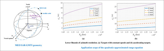
Figure 1 illustrates the MEO SAR-GMTI geometry. In Figure 1, OX’Y’Z’ is the Earth-centered inertial (ECI) coordinate system, with the origin being the center of mass of Earth, the OX’ axis pointing to the vernal equinox, the OZ’ axis pointing to the north pole, and the OY’ axis completing a right-hand Cartesian coordinate system. OXYZ is the Earth-centered rotating (ECR) coordinate system, with the origin and the OZ axis identical to those of the ECI coordinate system, the OX axis pointing to the intersection of the prime meridian and the equatorial plane, and the OY axis completing a right-hand Cartesian coordinate system. Assuming that at the azimuth slow time ta = 0, the beam center of the radar crosses the target, and the longitude and the latitude of the target are δlng and δlat, respectively. At ta = 0, in the ECR coordinate system, the target is assumed to move with the velocity components vlng and vlat and constant acceleration components alng and alat along the lines of the longitude and latitude, respectively.
According to the kinematics of the satellite, the satellite’s coordinates in the ECI coordinate system can be expressed as [32]
with
where f (ta) is the true anomaly of the satellite, Rs(ta) is the distance between the satellite and the center of mass of Earth, a is the orbit’s semi-major axis, e is the orbit’s eccentricity, ω presents the argument of perigee, Ω presents the right ascension of ascending node, and i presents the orbit’s inclination.
According to the definitions of the ECI and ECR coordinate systems, the transformation matrix between them is as follows:
with
where ΩG(ta) is the Greenwich Hour Angle at ta, ΩG0 is the Greenwich Hour Angle at ta = 0, and ωe is the Earth’s rotational angular velocity. Therefore, in the ECR coordinate system, the coordinates of the satellite are as follows:
From now on, the ECI coordinate system is disregarded, and the following studies are based on the ECR coordinate system.
Assuming that the Earth is locally flat, according to Figure 1, the coordinates of the target are given by
where Re is the radius of Earth.
3. Range Equation Modeling
The range equation of a target is a very important parameter for SAR imaging and SAR-GMTI. A target’s azimuth phase modulation, RCM, ATI phase, and steering vector are all depended on its range equation. Therefore, many range equation models have been proposed, among which the quadratic-approximated (i.e., the second-order Taylor approximated) range equation is the preferred one for SAR-GMTI. It benefits the derivation of a signal model of concise form and the design of GMTI methods (e.g., the motion parameters estimation methods) [7]. Therefore, in this section, the target’s quadratic-approximated range equations for the multichannel MEO SAR-GMTI system are derived. For the sake of clarity, the derivations of the quadratic-approximated range equation for the reference channel and the nth channel are presented separately.
In the following derivations, it is assumed that the antenna is accurately zero-Doppler steered, which is very common for modern spaceborne SAR systems [27]. Moreover, the baseline error is considered in the derivation of the quadratic-approximated range equation for the nth channel.
3.1. Derivation of the Quadratic-Approximated Range Equation for the Reference Channel
Assuming that the MEO SAR has N channels in azimuth (see Figure 2), and the position vector of the reference channel (the first channel) is rs(ta) = [xs(ta) ys(ta) zs(ta)]. Then, the range equation of the target with respect to the reference channel, i.e., the instantaneous distance between the target and the reference channel, is as follows:
where R(ta) = rt(ta) − rs(ta) is the range vector from the satellite to the target, rt(ta) = [xt(ta) yt(ta) zt(ta)] is the target’s position vector, and superscript “T” represents the vector transpose. Note that in the paper, a bold letter represents a vector, and the corresponding regular italic font represents the magnitude of the vector.
The quadratic-approximated range equation can be obtained by taking a second-order Taylor series expansion to the range equation at the beam center crossing time (i.e., ta = 0). By using the principles of matrix differential, the quadratic-approximated range equation of the reference channel is expressed as
with
where Rq(ta) is the target’s quadratic-approximated range equation of the reference channel, and are the velocity and acceleration vectors of the reference channel, respectively, and are the velocity and acceleration vectors of the target, respectively.
To obtain an expression of concise form for the quadratic-approximated range equation, by utilizing the vector projection, l1 and l2 are simplified as follows:
with
where vtr and atr are the projections of the target’s velocity and acceleration onto the radial direction, respectively, vsr and asr are the projections of the satellite’s velocity and acceleration onto the radial direction, respectively, vta is the projection of the target’s velocity onto the direction of the satellite’s velocity vector. All of these parameters are defined at the beam center crossing time. vt0 = |vt(0)| and vs0 = |vs(0)| are the velocity of the target and the satellite at ta = 0, respectively. Note that since the zero-Doppler steering is assumed, vsr is equal to zero.
Based on (14) and (15), one can obtain an expression of concise form for the quadratic-approximated range equation as follows:
Remark .
In the fields of SAR-GMTI, the estimation of a target’s motion parameters is usually accomplished via the estimation of the first-order and second-order coefficients of its range equation. Therefore, the derivation of an expression of concise form for the quadratic-approximated range equation will benefit the design of motion parameters estimation methods, because it can clearly reveal the relationships between the motion parameters and the coefficients of the range equation.
3.2. Derivation of the Quadratic-Approximated Range Equation for the nth Channel
Due to the zero-Doppler steering, the azimuth axis of the antenna is parallel to the satellite’s velocity vector vs(ta), as shown in Figure 2. Therefore, the position vector of the effective phase center of the nth (n = 1, 2, …, N) channel is given by
where d is the nominal baseline (i.e., the distance between adjacent effective phase centres) and is the baseline error (). Thus, the target’s range equation of the nth channel can be expressed as
To obtain the expression for the quadratic-approximated range equation of the nth channel, the expressions for , , and are derived in the following.
The expression of Rn(0) can be easily obtained by definition
where has been ignored because it is far smaller than rt(0)-rs(0). Note that the norm of is in the order of 1 m, while the norm of rt(0)-rs(0) is in the order of 107 m.
The expression for is derived as follows:
where the term is ignored because it is very small (it is in the order of 10−13 m/s).
The expression for is derived as follows:
where are the jerk vector of the satellite, and the double-dot notation indicates the second derivative with respect to ta.
Based on (23)–(26), the quadratic-approximated range equation of the nth channel is as follows:
Remark .
For multichannel SAR-GMTI, the steering vector and ATI phase of a target are very important for the design of methods for clutter suppression, motion and position parameters estimation, and detection [7]. Their analytical expressions can be obtained by comparing the range equations of the reference channel and the nth channel [7,33]. Therefore, the derivation of the quadratic-approximated range equation for the nth channel will also facilitate the design of SAR-GMTI methods.
4. Investigation on the Accuracy of the Quadratic-Approximated Range Equation
The quadratic-approximated range equation’s accuracy is generally sufficient for RCM correction. However, for azimuth compression, the quadratic approximation of the target’s range equation will lead to a phase error that could result in azimuth defocusing and a loss of the target’s peak power in SAR image when it is larger than π/4 [34]. This section will derive such an analytical expression for this phase error that can reveal its dependence on the parameters of the radar and the target.
The phase error caused by the quadratic approximation can be calculated as
where λ is the wavelength, and Ta is the target’s illumination time. Ta depends on the target’s distance and the azimuth resolution, and it can be approximately expressed as Ta ≈ λR0/(2ρavs0), where ρa is the azimuth resolution [19]. It should be noted that since the phase error of the reference channel and that of the nth channel are almost identical (we will validate this statement in Section 5), the range equation of the reference is utilized to investigate the phase error.
This phase error is mainly determined by the cubic term of the target’s range equation because the higher terms are much smaller than the cubic term (we will validate this statement in Section 6). Therefore, the phase error can be calculated as
where l3 is the coefficient of the cubic term. To obtain such an analytical expression for Φ that can reveal its dependence on the parameters of the radar and the target, the expression of l3 is derived and simplified as follows:
Since the terms containing and are very small, and is far smaller than , they can be ignored. (Assuming that the parameters of the target are: vlng = 10 m/s, vlat = 8 m/s, alng = 0.4 m/s2, alat = 0.3 m/s2, δlat = 10°, δlng = 30°, R0= 1.12 × 10⁴ km, and other parameters are the same as those given in Table 1. Then, the terms containing and are in the orders of 10−7 m/s3 and 10−12 m/s3, respectively, is in the order of 1 m2/s3 while is in the order of 103 m2/s3.) Therefore, (30) can be simplified to
where asa and ata are the projection of the accelerations of the satellite and the target onto the direction of the satellite’s velocity vector at the beam center crossing time, respectively, and is the projection of the satellite’s jerk onto the radial direction at the beam center crossing time.
According to (29) and (31), one can obtain an analytical expression for the phase error as follows:
The phase error’s dependence on the parameters of the radar and the target is revealed in (32), and the following points can be noted.
- (1)
- The phase error is strongly sensitive to the azimuth resolution and the wavelength. It is approximately proportional to the square of the wavelength and inversely proportional to the cube of the azimuth resolution.
- (2)
- The phase error is proportional to the distance between the target and the MEO SAR and is inversely proportional to the speed of the MEO SAR. In addition, the phase error depends on the target’s along-track acceleration, while the dependency between the phase error and the target’s radial acceleration and along-track velocity can be ignored.
- (3)
- Different from LEO SAR, the dependency between the phase error and the target’s radial velocity can be neglected. Moreover, in the case of MEO SAR, the phase error depends also on the projection of the satellite’s acceleration onto the direction of its velocity vector and the projection of the satellite’s jerk onto the radial direction.
5. Numerical Results
In this section, first, numerical simulations are carried out to quantitatively investigate the phase error due to the quadratic approximation. Then, the SNR loss and parameter estimation accuracy loss caused by the phase error are investigated. Finally, the quadratic-approximated range equation’s scope of application is studied. The main orbit parameters of the satellite used in the numerical simulations are presented in Table 1.
5.1. Phase Error
First, simulations were carried out to study the dependence of the phase error on the target’s motion parameters. The results are presented in Figure 3 and Figure 4, which show the dependence of the phase error on the target’s velocities and accelerations, respectively. In Figure 3 and Figure 4, the color indicates the value of the phase error, and the unit is radian. From Figure 3a,b one can see that the dependency between the phase error and the target’s velocities is relatively small. From Figure 4a,b it can be seen that the dependency between the phase error and the target’s along-track acceleration is significant, while there is no obvious dependency between the phase error and the target’s radial acceleration. Moreover, it is seen that the numerical results agree with the theoretical analysis presented in Section 4. Furthermore, from Figure 3c and Figure 4c, it can be seen that the differences between phase error in the reference channel and the second channel are so small that can be ignored. Therefore, in the following simulations and analyses, only the range equation of the reference channel is utilized to study the accuracy of the quadratic-approximated range equation. The parameters of the radar and the target used in the simulations are given in Table 2. Note that in Table 2, the target’s latitude is chosen randomly. The phase error is mainly depended on the distance between the target and the radar (this distance is mainly depended on the target’s longitude). The dependence between the phase error and the target’s latitude is relatively small, and the phase error increases slightly with the increase of the latitude.
Secondly, simulations were conducted to investigate the phase error’s dependence on the parameters of the radar, and the results are shown in Figure 5, Figure 6 and Figure 7. Note that to illustrate the influence of the wavelength on the phase error, the X band (10 GHz), the C band (5.4 GHz), and the S band (3.3 GHz) systems were considered in the simulations. In addition, in the simulations, the latitude of the target was set fixedly to be 10°, while the longitude of the target was set to range from 21° to 77° with a step size of 2°. The change of the distance between the target and the radar was accomplished by the change of the target’s longitude. Furthermore, the azimuth resolution was set to be 10 m in the simulations.
Figure 5, Figure 6 and Figure 7 show the dependence of the phase error on the azimuth resolution and the distance. In addition, in Figure 5, Figure 6 and Figure 7, the color indicates the value of the phase error, and the unit is radian. Note that the phase errors illustrated in Figure 5, Figure 6 and Figure 7 are calculated as follows:
where Φcnst and Φaccare the phase errors for the target with constant velocity and the accelerating target, respectively. From (33) and (34) one can see that the phase errors shown in Figure 5, Figure 6 and Figure 7 are chosen to be the maximum value among the possible motion parameters.
From Figure 5, Figure 6 and Figure 7 one can see that the phase error increases significantly with the decreasing of the azimuth resolution and the increasing of the distance and wavelength, as indicated by (32). It can also be seen that the phase errors of accelerating targets are much larger than those of targets with constant speeds. Specifically, by comparing Figure 5a,b, one can see that the maximum phase error of accelerating targets are over ten times larger than that of targets with constant speeds. Similar results can be found via comparing Figure 6a,b and Figure 7a,b respectively. In addition, by comparing Figure 5 with Figure 6, it can be seen that the phase error of the C band system is over three times larger than that of the X band system.
5.2. Influence of the Phase Error on the GMTI Performance
The phase error may lead to a significant loss of the target’s peak power in SAR image and thus the loss of signal-to-noise ratio (SNR). The loss of SNR will result in the degradation of the GMTI performance, such as the degradation of the accuracy of the parameter estimation. In this subsection, numerical simulations are carried out to investigate the dependence of the SNR loss on the phase error, and the dependence of the loss of the achievable radial velocity estimation accuracy and azimuth repositioning accuracy on the phase error.
Figure 8 shows the dependence of the SNR loss on the phase error. As can be seen from Figure 8, the SNR loss is proportional to the phase error, and the SNR loss exceeds 3 dB when the phase error is larger than 2.5 radian. In the simulations, the parameters of the MEO SAR and the target for the simulations are: λ = 0.03 m, δlat = 10°, δlng = 30°, R0 = 1.12 × 10⁴ km. The change of the phase error is accomplished by the change of the azimuth resolution. Note that for targets with different parameters, the relationships between the phase error and the SNR loss are almost the same.
For multichannel SAR-GMTI, the achievable radial velocity estimation and azimuth repositioning accuracy depend on the target’s SNR, and their relationships can be expressed as [35,36].
where σra and σvtr are the achievable minimum azimuth repositioning error and minimum radial velocity estimation error, respectively, La is the antenna length in azimuth.
According to (35) and (36), Figure 9 shows the dependence of the losses of the achievable radial velocity estimation accuracy and azimuth repositioning accuracy on the phase error. It can be seen that there will be a loss of about 29% in achievable estimation accuracy when the phase error is 2.5 radian (the corresponding SNR loss is 3 dB).
5.3. Quadratic-Approximated Range Equation’s Scope of Application
This subsection studies the quadratic-approximated range equation’s scope of application based on the investigations conducted in Section 5.1 and Section 5.2. The maximum acceptable SNR loss is set to be 3 dB, and thus the upper bound for the phase error is 2.5 radian.
In the simulations, four typical carrier frequencies were considered: 10 GHz (X Band), 5.4 GHz (C band), 3.3 GHz (S band), and 1.3 GHz (L band). The results are shown in Figure 10. The curves in Figure 10 represent the lower bound of the azimuth resolution to let the phase error be less than 2.5 radian. For example, from Figure 10a one can see that when Rc is 1.2 × 10⁴ km, to let the phase error of targets moving with constant speed be less than 2.5 radian, the lower bounds of azimuth resolution for the X, C, S, and L band systems are about 2.5 m, 3.5 m, 5.0 m, and 9.5 m, respectively. The areas above each curve in Figure 10 are actually the cases where the quadratic-approximated range equation is applicable.
From Figure 10a one can also see that when the target moves with constant speed, the accuracy of the quadratic-approximated range equation may be sufficient as long as the azimuth resolution of the MEO SAR-GMTI system is not very high. From Figure 10b it is seen that for the target moves with accelerations, the quadratic-approximated range equation is applicable to the MEO SAR-GMTI systems with medium or low azimuth resolutions.
6. Discussion
In Section 5, numerical experiments have been carried out to quantitatively investigate the accuracy of the quadratic-approximated range equation via analyzing the phase error. In addition, the influence of the phase error on the GMTI performance has been investigated via analyzing the SNR loss and the parameter estimation accuracy loss caused by the phase error. Moreover, simulations have also been carried out to find out the quadratic-approximated range equation’s scope of application.
The results presented in Section 5.1 illustrate the relationship between the phase error and the parameters of the target and radar. The results validate the theoretical analysis presented in Section 4, i.e., the dependency between the phase error and the target’s radial velocity, along-track velocity, and radial acceleration is negligible; the phase error is proportional to the radar’s wavelength and distance, and inversely proportional to the azimuth resolution.
The results shown in Section 5.2 illustrate the SNR loss caused by the phase error. It is shown that there will be a loss of 3 dB in SNR when the phase error is 2.5 radian. In Section 5.3, with the upper bound for the phase error being set to be 2.5 radian, the quadratic-approximated range equation’s scope of application has been figured out. It should be noted that for precise ground moving target imaging the phase error should be less than π/4 radian.
As indicated in Section 5.3, the accuracy of the quadratic-approximated range equation will be insufficient when the azimuth resolution is very high. We have worked out that the accuracy of cubic-approximated range equation is sufficient even when the azimuth resolution is very high (the derivation of the cubic term is presented in Section 4). Figure 11 illustrates the dependence of the phase error on the azimuth resolution and the distance, with the color indicating the value of the phase error (the unit is radian). Figure 12 illustrates the cubic-approximated range equation’s scope of application. From Figure 11 and Figure 12, one can see that the cubic-approximated is accurate enough even when the azimuth resolution is very high. Moreover, by comparing Figure 11 with Figure 6, it can be seen that the phase errors of the cubic-approximated range equation are much smaller than those of the quadratic-approximated range equation. Therefore, it could be concluded that the phase error of the quadratic-approximated range equation is mainly depended on the cubic term.
7. Conclusions
A study on the range equation modeling for multichannel MEO SAR-GMTI systems has been presented in this paper. The coordinates of the multichannel MEO SAR and the target in the ECR coordinate system, as well as the target’ range equation with respect to each channel, have been developed in the paper. The analytical expression has also been derived for the target’s quadratic-approximated range equation of each channel. Moreover, the dependence of the accuracy of the quadratic-approximated range equation on the parameters of the radar and the target has been figured out. Finally, the influence of the phase error on the GMTI performance and the quadratic-approximated range equation’s scope of application have been studied via numerical simulations.
Author Contributions
The research presented in this manuscript was accomplished in collaboration with all of the authors. Y.L. proposed the idea, carried out the theoretical derivations and analyses, conducted the numerical simulations, wrote the manuscript. T.W. validated the theoretical derivations and analyses, reviewed the manuscript. T.H. conducted the numerical simulations, proofed the manuscript. L.N. reviewed the manuscript. All authors have read and agreed to the published version of the manuscript.
Funding
This paper was funded by the Postdoctoral Science Foundation of under Grants BX20180261 and 2019M653739, and by the Aeronautical Science Foundation of China under Grant ASFC-20200020053001.
Institutional Review Board Statement
Not applicable.
Informed Consent Statement
Not applicable.
Data Availability Statement
The data presented in this study are available on request from the corresponding author.
Acknowledgments
The authors would like to thank the anonymous reviewers for their valuable comments.
Conflicts of Interest
The authors declare no conflict of interest.
Abbreviations
The abbreviations used in this manuscript are as follows:
| SAR | synthetic aperture radar |
| GMTI | ground moving target indication |
| RCM | range cell migration |
| ATI | along-track interferometric |
| LEO | low-Earth-orbit |
| MEO | medium-Earth-orbit |
| ECI | Earth-centered inertial |
| ECR | Earth-centered rotating |
| SNR | signal-to-noise ratio |
References
- Moreira, A.; Prats-iraola, P.; Younis, M.; Krieger, G.; Hajnsek, I.P.; Papathanassiou, K. A Tutorial on Synthetic Aperture Radar. IEEE Mag. Geosci. Remote Sens. 2013, 1, 6–43. [Google Scholar] [CrossRef] [Green Version]
- Ren, Y.; Tang, S.Y.; Guo, P.; So, H.C.; Zhang, L.R. 2-D Spatially Variant Motion Error Compensation for High-Resolution Airborne SAR Based on Range-Doppler Expansion Approach. IEEE Trans. Geosci. Remote Sens. 2021, in press. [Google Scholar] [CrossRef]
- Tang, S.Y.; Guo, P.; Zhang, L.R.; So, H.C. Focusing Hypersonic Vehicle-Borne SAR Data Using Radius/Angle Algorithm. IEEE Trans. Geosci. Remote Sens. 2020, 58, 281–293. [Google Scholar] [CrossRef]
- Chen, J.L.; Zhang, J.C.; Jin, Y.H.; Yu, H.W.; Liang, B.G.; Yang, D.G. Real-Time Processing of Spaceborne SAR Data with Nonlinear Trajectory Based on Variable PRF. IEEE Trans. Geosci. Remote Sens. 2021, in press. [Google Scholar]
- Wang, L.; Bai, X.R.; Gong, C.; Zhou, F. Hybrid Inference Network for Few-Shot SAR Automatic Target Recognition. IEEE Trans. Geosci. Remote Sens. 2021, in press. [Google Scholar]
- Li, Y.K.; Liu, B.C.; Wang, L.; Chen, H.M.; Nie, L.S.; Zeng, L.N.; Bi, G.A. An accurate imaging and doppler chirp rate estimation algorithm for airborne CSSAR-GMTI systems. IEEE Access 2019, 7, 170077–170086. [Google Scholar] [CrossRef]
- Baumgartner, S.V.; Krieger, G. Multi-Channel SAR for ground Moving Target Indication. Elsevier Acad. Press Libr. Signal Process. 2014, 2, 911–986. [Google Scholar]
- Dragoševic, M.V.; Henschel, M.D.; Livingstone, C.E. An Approach to Ship Motion Estimation With Dual-Receive Antenna SAR. In Proceedings of the 2008 IEEE Radar Conference, Rome, Italy, 26–30 May 2008; pp. 1–6. [Google Scholar]
- Zhang, X.P.; Liao, G.S.; Zhu, S.Q.; Yang, D.; Du, W.T. Efficient Compressed Sensing Method for Moving Targets Imaging by Exploiting the Geometry Information of the Defocused Results. IEEE Geosci. Remote Sens. Lett. 2015, 12, 517–521. [Google Scholar] [CrossRef]
- Henke, D.; Dominguez, E.M.; Small, D.; Schaepman, M.E.; Meier, E. Moving-Target Tracking in Single-Channel Wide-Beam SAR. IEEE Trans. Geosci. Remote Sens. 2015, 50, 4735–4747. [Google Scholar] [CrossRef] [Green Version]
- Bacci, A.; Martorella, M.; Gray, D.A.; Berizzi, F. Space-Doppler Adaptive Processing for Radar Imaging of Moving Targets Masked by Ground Clutter. IET Radar Sonar Navig. 2015, 9, 712–726. [Google Scholar] [CrossRef]
- Wan, J.; Tan, X.; Chen, Z.; Dong, L.; Liu, Q.; Zhou, Y.; Zhang, L. Refocusing of Ground Moving Targets with Doppler Ambiguity Using Keystone Transform and Modified Second-Order Keystone Transform for Synthetic Aperture Radar. Remote Sens. 2021, 2, 177. [Google Scholar] [CrossRef]
- Cerutti-Maori, D.; Sikaneta, I.; Gierull, C.H. Optimum SAR/GMTI Processing and Its Application to the Radar Satellite RADARSAT-2 For Traffic Monitoring. IEEE Trans. Geosci. Remote Sens. 2012, 50, 3868–3881. [Google Scholar] [CrossRef]
- Chiu, S. Moving Target Indication Via RADARSAT-2 Multichannel Synthetic Aperture Radar Processing. EURASIP J. Adv. Signal Process. 2010, 2010, 1–19. [Google Scholar] [CrossRef] [Green Version]
- Rousseau, L.P.; Gierull, C.H.; Chouinard, J.Y. First Results from an Experimental SCANSAR-GMTI Mode on RADARSAT-2. IEEE J. Sel. Top. Appl. Earth Observ. Remote Sens. 2015, 8, 5068–5080. [Google Scholar] [CrossRef]
- Pastina, D.; Turin, F. Exploitation of the COSMO-SkyMed SAR System for GMTI Applications. IEEE J. Sel. Top. Appl. Earth Observ. Remote Sens. 2015, 8, 966–979. [Google Scholar] [CrossRef]
- Baumgartner, S.V.; Krieger, G. Dual-Platform Large Along-Track Baseline GMTI. IEEE Trans. Geosci. Remote Sens. 2016, 3, 1554–1574. [Google Scholar] [CrossRef]
- Budillon, A.; Gierull, C.H.; Pascazio, V.; Schirinzi, G. Along Track Interferometric SAR systems for Ground Moving Target Indication: Achievements, Potentials and Outlook. IEEE Mag. Geosci. Remote Sens. 2020, 8, 46–63. [Google Scholar] [CrossRef]
- Huang, L.J. Imaging Algorithm for Medium-Earth-Orbit SAR. Ph.D. Thesis, Graduate University of Chinese Academy of Sciences, Beijing, China, 2010. [Google Scholar]
- Matar, J.; López-Dekker, P.; Krieger, G. Potentials and Limitations of MEO SAR. In Proceedings of the EUSAR 2016: 11th European Conference on Synthetic Aperture Radar, Hamburg, Germany, 6–9 June 2016; pp. 1035–1039. [Google Scholar]
- Bao, M.; Xing, M.D.; Wang, Y.; Li, Y.C. Two-dimensional Spectrum For MEO SAR Processing Using a Modified Advanced Hyperbolic Range Equation. Electron. Lett. 2011, 47, 1–2. [Google Scholar] [CrossRef]
- Huang, L.J.; Qiu, X.; Hu, D.; Ding, C. Focusing of Medium-Earth-Orbit SAR with Advanced Nonlinear Chirp Scaling Algorithm. IEEE Trans. Geosci. Remote Sens. 2011, 49, 500–508. [Google Scholar] [CrossRef]
- Huang, L.J.; Qiu, X.; Hu, D.; Han, B.; Ding, C. Medium-Earth-orbit SAR Focusing Using Range Doppler Algorithm with Integrated Two-Step Azimuth Perturbation. IEEE Geosci. Remote Sens. Lett. 2015, 12, 626–630. [Google Scholar] [CrossRef]
- Wang, P.B.; Liu, W.; Chen, J.; Yang, W.; Han, Y. Higher Order Nonlinear Chirp Scaling Algorithm for Medium Earth Orbit Synthetic Aperture Radar. J. Appl. Remote Sens. 2015, 9, 096084. [Google Scholar] [CrossRef] [Green Version]
- Chen, J.L.; Xing, M.D.; Sun, G.C.; Gao, Y.X.; Liu, W.K.; Guo, L.; Lan, Y. Focusing of Medium-Earth-Orbit SAR Using an ASE-Velocity Model Based on MOCO Principle. IEEE Trans. Geosci. Remote Sens. 2018, 56, 3963–3975. [Google Scholar] [CrossRef]
- Liu, W.K.; Sun, G.C.; Xia, X.G.; Chen, J.L.; Guo, L.; Xing, M.D. A Modified CSA Based on Joint Time-Doppler Resampling For MEO SAR Stripmap Mode. IEEE Trans. Geosci. Remote Sens. 2018, 56, 3573–3586. [Google Scholar] [CrossRef]
- Cumming, I.G.; Wong, F.H. Digital Processing of Synthetic Aperture Radar Data: Algorithm and Implementation; Artech House: Norwood, MA, USA, 2004. [Google Scholar]
- Li, Z.F.; Bao, Z.; Wang, H.Y.; Liao, G.S. Performance Improvement for Constellation SAR Using Signal Processing Techniques. IEEE Trans. Aerosp. Electron. Syst. 2006, 42, 436–452. [Google Scholar]
- Ma, L.; Li, Z.F.; Liao, G.S. System Error Analysis and Calibration Methods for Multichannel SAR. PIER 2011, 112, 309–327. [Google Scholar] [CrossRef] [Green Version]
- Li, Y.K.; Nie, L.S. Study on the Range Equation Modeling of MEO SAR-GMTI systems. In Proceedings of the 6th Asia-Pacific Conference on Synthetic Aperture Radar, Xiamen, China, 26–29 November 2019; pp. 1–5. [Google Scholar]
- Li, Y.K.; Wang, F.; Zeng, L.N.; Chen, H.M. A Study on the Cubic Range Model for MEO SAR Ground Moving Target Imaging. In Proceedings of the IEEE International Conference on Signal Processing, Communications and Computing, Xi’an, China, 21–24 August 2020; pp. 1–4. [Google Scholar]
- Yuan, X. Introduce to the Spaceborne Synthetic Aperture Radar; National Defense Industry Press: Beijing, China, 2005. [Google Scholar]
- Li, Y.K.; Wang, Y.L.; Liu, B.C.; Zhang, S.X.; Nie, L.S.; Bi, G.A. A New Motion Parameter Estimation and Relocation Scheme for Airborne Three-Channel CSSAR-GMTI Systems. IEEE Trans. Geosci. Remote Sens. 2019, 57, 4107–4120. [Google Scholar] [CrossRef]
- Carrara, W.G.; Goodman, R.S.; Majewski, R.M. Spotlight Synthetic Aperture Radar Signal Processing Algorithms; Artech House: New York, NY, USA, 1995. [Google Scholar]
- Gierull, C.H.; Cerutti-Maori, D.; Ender, J. Ground Moving Target Indication with Tandem Satellite Constellations. IEEE Geosci. Remote Sens. Lett. 2008, 5, 710–714. [Google Scholar] [CrossRef]
- Ender, J.; Gierull, C.H.; Cerutti-Maori, D. Improved Space-Based Moving Target Indication via Alternate Transmission and Receiver Switching. IEEE Trans. Geosci. Remote Sens. 2008, 46, 3960–3974. [Google Scholar] [CrossRef]
Figure 1.
MEO SAR-GMTI geometry.

Figure 2.
Geometry of the multichannel MEO SAR.

Figure 3.
Dependency between the phase error and vta and vtr. (a) The reference channel, (b) the 2th channel, and (c) the difference between phase error in the reference channel and the 2th channel. The target’s accelerations are set to be: ata = 0.5 m/s2, atr = −0.4 m/s2. In the figures, the color indicates the value of the phase error, and the unit is radian.

Figure 4.
Dependency between the phase error and ata and atr. (a) The reference channel, (b) the 2th channel, and (c) the difference between phase error in the reference channel and the 2th channel. The target’s velocities are set to be: vta = −10 m/s, vtr = 12 m/s. In the figures, the color indicates the value of the phase error, and the unit is radian.


Figure 5.
Dependency between the phase error and ρa and R0 for the X band system. (a) Targets with constant speeds and (b) accelerating targets. In the figures, the color indicates the value of the phase error, and the unit is radian.
Figure 5.
Dependency between the phase error and ρa and R0 for the X band system. (a) Targets with constant speeds and (b) accelerating targets. In the figures, the color indicates the value of the phase error, and the unit is radian.

Figure 6.
Dependency between the phase error and ρa and R0 for the C band system. (a) Targets with constant speeds and (b) accelerating targets. In the figures, the color indicates the value of the phase error, and the unit is radian.
Figure 6.
Dependency between the phase error and ρa and R0 for the C band system. (a) Targets with constant speeds and (b) accelerating targets. In the figures, the color indicates the value of the phase error, and the unit is radian.

Figure 7.
Dependency between the phase error and ρa and R0 for the S band system. (a) Targets with constant speeds and (b) accelerating targets. In the figures, the color indicates the value of the phase error, and the unit is radian.
Figure 7.
Dependency between the phase error and ρa and R0 for the S band system. (a) Targets with constant speeds and (b) accelerating targets. In the figures, the color indicates the value of the phase error, and the unit is radian.

Figure 8.
Dependence of the SNR loss on the phase error.

Figure 9.
Dependence of the achievable estimation accuracy loss on the phase error.

Figure 10.
Lower Bounds of azimuth resolution. (a) Targets with constant speeds and (b) accelerating targets.
Figure 10.
Lower Bounds of azimuth resolution. (a) Targets with constant speeds and (b) accelerating targets.

Figure 11.
Dependency between the phase error of the cubic-approximated range equation and ρa and R0 for the C band system. (a) Targets with constant speeds and (b) accelerating targets. In the figures, the color indicates the value of the phase error, and the unit is radian.
Figure 11.
Dependency between the phase error of the cubic-approximated range equation and ρa and R0 for the C band system. (a) Targets with constant speeds and (b) accelerating targets. In the figures, the color indicates the value of the phase error, and the unit is radian.

Figure 12.
Lower Bounds of azimuth resolution for the cubic-approximated range equation. (a) Targets with constant speeds and (b) accelerating targets.
Figure 12.
Lower Bounds of azimuth resolution for the cubic-approximated range equation. (a) Targets with constant speeds and (b) accelerating targets.


Table 1.
Orbit parameters for the numerical simulations.
| Parameter | Value |
|---|---|
| Height of the orbit | 10,000 km |
| Radius of the Earth | 6371 km |
| Right ascension of ascending node | 0 |
| Argument of perigee | 0 |
| Orbit inclination | 90° |
| Eccentricity | 0 |
| Greenwich hour angle at ta = 0 | 0 |
Table 2.
Parameters of the MEO SAR and the target for the simulations.
| Parameter | Value |
|---|---|
| λ | 0.056 m |
| d | 4 m |
| ρa | 10 m |
| δlat | 10° |
| δlng | 30° |
| Ta | 6.26 s |
| PRF | 500 Hz |
| R0 | 1.12 × 10⁴ km |
Publisher’s Note: MDPI stays neutral with regard to jurisdictional claims in published maps and institutional affiliations. |
© 2021 by the authors. Licensee MDPI, Basel, Switzerland. This article is an open access article distributed under the terms and conditions of the Creative Commons Attribution (CC BY) license (https://creativecommons.org/licenses/by/4.0/).
Share and Cite
MDPI and ACS Style
Li, Y.; Wang, T.; Huo, T.; Nie, L. A Study on the Range Equation Modeling for Multichannel Medium-Earth-Orbit SAR-GMTI Systems. Remote Sens. 2021, 13, 2734. https://doi.org/10.3390/rs13142734
AMA Style
Li Y, Wang T, Huo T, Nie L. A Study on the Range Equation Modeling for Multichannel Medium-Earth-Orbit SAR-GMTI Systems. Remote Sensing. 2021; 13(14):2734. https://doi.org/10.3390/rs13142734
Chicago/Turabian StyleLi, Yongkang, Tong Wang, Tianyu Huo, and Laisen Nie. 2021. "A Study on the Range Equation Modeling for Multichannel Medium-Earth-Orbit SAR-GMTI Systems" Remote Sensing 13, no. 14: 2734. https://doi.org/10.3390/rs13142734
Note that from the first issue of 2016, this journal uses article numbers instead of page numbers. See further details here.