Design and Analysis of a UWB MIMO Radar System with Miniaturized Vivaldi Antenna for Through-Wall Imaging
by
 , ,
, ,
Zhipeng Hu
1, 
Zhaofa Zeng
1,*,
Kun Wang
1,2,
Weike Feng
3,
Jianmin Zhang
1,
Qi Lu
1 and
Xiaoqian Kang
1 1
College of Geo-Exploration Science and Technology, Jilin University, Changchun 130026, China
2
School of Mining and Safety Engineering, Shandong University of Science and Technology, Qingdao 266590, China
3
Graduate School of Environmental Studies, Tohoku University, Sendai 980-8579, Japan
*
Author to whom correspondence should be addressed.
Remote Sens. 2019, 11(16), 1867; https://doi.org/10.3390/rs11161867
Submission received: 26 June 2019
/
Revised: 5 August 2019
/
Accepted: 7 August 2019
/
Published: 9 August 2019
(This article belongs to the Special Issue Radar Imaging in Challenging Scenarios from Smart and Flexible Platforms)
Abstract
:The ultra-wideband (UWB) multi-input multi-output (MIMO) radar technique is playing a more and more important role in the application of through-wall detection because of its high resolution, lower antenna requirements, and efficient data capturing ability. This paper develops a novel UWB MIMO radar system using a stepped-frequency continuous-wave (SFCW) signal, which is designed to detect human targets behind the regular brick and concrete wall. In order to balance high range resolution and wall-penetration depth, a novel miniaturized Vivaldi antenna with desired bandwidth of 0.5–2.5 GHz was designed, simulated, manufactured, and successfully used in through-wall imaging. To suppress the artifacts in the focused image and reduce the computing complexity, the cross-correlation-based time domain back projection (CC-TDBP) algorithm was developed. In addition, a through-wall imaging model was established, based on which the effects of the wall on the refraction of electromagnetic (EM) waves and the reduction of velocity are compensated. Finally, different experiments were conducted for multiple stationary targets utilizing the designed radar system, and the improved BP-based algorithms are applied to focus the targets behind the wall more accurately. The reconstructed two-dimensional (2D) images illustrate that the designed MIMO radar system can successfully detect and image human targets in the air and behind the wall.
1. Introduction
Ultra-wideband (UWB) through-wall radar (TWR), as an emerging technology, is used to detect targets blocked by obstacles. It has wide application prospects in military and civil fields, such as urban combat, antiterrorism, vigilance, security inspection, disaster rescue, and so on [1,2,3,4,5,6]. According to the working mode, TWR can be divided into synthetic aperture radar (SAR) systems and MIMO radar systems [7,8,9,10,11,12,13]. Conventionally, to get a high azimuth resolution, the synthetic aperture method (SAR) is extensively used. The transceiver of a SAR system is sequentially sled on a rail to provide synthetic aperture scanning imaging. However, this method requires long data acquisition times and its azimuth resolution is limited by the length of the rail. In addition, the TWR of the SAR mode has the disadvantage of large scale and high cost [10,11,12,13]. In this case, the MIMO radar technology provides a new platform to solve the above problems [7,8,9,14,15,16,17,18,19,20].
The MIMO radar technology was proposed in 2003 and 2004 [14,15]. It uses multiple transmitting and receiving antennas and transmits orthogonal waveforms, which can expand the aperture of the actual array elements and confer a better spatial sampling ability. In addition, the sparse MIMO array design of switched antenna can also meet the requirements of high scanning speed and detection ability in the practical application of through-wall imaging. Therefore, the switched antenna array radar is often considered as the MIMO radar. In recent years, the MIMO radar system has received extensive attention of scholars. Amin et al. [1,4] proposed the ‘co-array’. The azimuth resolution of the imaging is improved by expanding the aperture of the virtual array which is formed by the transceiver array. Zhuge et al. [18,19] studied the equivalence of a UWB MIMO array using the point spread function (PSF). It is pointed out that the equivalent array is the spatial convolution of the PSF of the transmitting array and the receiving array in the far field. Based on this, a linear array design was proposed. Feng et al. [20] developed a MIMO array-based radar system using a SFCW signal, which can effectively improve the data sampling speed, maintain the azimuth resolution, and reduce the hardware costs. However, due to the high frequency range of the antenna used, the penetration depth of the radar system is too shallow for through-wall imaging. Yılmaz et al. [6] designed and manufactured a uniform array radar system to detect and image targets behind a wall with a monostatic configuration controlled by a switcher. However, the effect of the wall on the refraction of EM waves, which produces a position shift of the targets behind the wall, was ignored.
Based on the advantages and limitations of the above research results, a UWB MIMO sparse array radar system with eight pairs of transmitting and receiving miniaturized Vivaldi antennas is studied in this paper and is mainly used for 2D imaging of multiple targets behind a wall. The UWB MIMO system combines UWB technology with MIMO technology. On one hand, UWB technology can improve range resolution [21,22]. On the other hand, the sparse topology of the MIMO system can obtain larger array aperture and smaller element spacing by using fewer antennas. Moreover, higher azimuth resolution and better main/side lobe control are obtained. Therefore, the MIMO radar system only needs a few physical elements to achieve the same imaging effect as SAR. In this way, the number of array elements and the system cost are greatly reduced, while the aperture length is maintained. In addition, the electronic switching mode used in the MIMO radar system can improve the data acquisition speed.
In the MIMO radar system, the antenna is of great importance as it radiates power to the wall and detects the signals of the targets. UWB signals are suitable for the radar system while the through-wall penetration losses for general wall materials increase with frequency. On the other hand, lower working frequency band for antennas can provide better through-wall penetration but this also implies a larger size of the antenna [23]. Hence, the antenna working frequency range of 0.5–2.5 GHz is considered to balance good resolution and strong penetration even for thick walls. In this paper, we apply Vivaldi antennas in a MIMO radar system for through-wall detection because of its many advantages, such as high gain, wide band, steady radiation patterns, simple structure, and simplicity of processing [24]. The low-frequency characteristic of antennas generally results in larger size. Inspired by [25,26], we use a slotted approach to change the surface current distribution to optimize performance throughout the band, expand the low frequency bandwidth, and reduce its size. Finally, the low-frequency UWB miniaturized Vivaldi antenna was designed and fabricated with dimensions of 250 mm × 200 mm × 1.6 mm, and a working band (the S11 is less than—10 dB) of 0.5–2.5 GHz, good end-fire radiation behavior, and acceptable gain. The Vivaldi antenna designed in this paper is one of the contributions to the imaging research of through-wall radar technology. The proposed antenna is simple, easy to fabricate, and is made of inexpensive FR4 substrate. The experiments show that the designed antenna has good through-wall penetration ability and resolution.
2D imaging is one of the most important signal processing steps for a through-wall MIMO radar system. The small imaging area is located in the near field of the radar. At the same time, EM waves produce reflections, attenuations, and velocity changes when they penetrate the wall. Therefore, the back projection (BP) imaging algorithm [9,20], which has no requirement for the array configuration, is one of the most practical through-wall imaging methods due to its convenience and robustness. However, reconstructed images of targets by the BP method may have some artifacts. In this paper, the cross-correlation-based time-domain BP algorithm (CC-TDBP) is applied to suppress artifacts [27,28]. Moreover, considering the effect of walls on the refraction and velocity of EM waves, an improved BP-based algorithm is proposed in Section 3. The experimental results validate that the designed MIMO radar system with the proposed BP-based algorithm can accurately reconstruct the human locations behind the wall.
The structure of the paper is organized as follows: In Section 2, the design process of the UWB MIMO array radar system is described. The imaging signal model and CC-TDBP algorithm are reviewed. The topology, array pattern of the designed MIMO array, and the 2D simulation imaging results are given. Moreover, the design methods of the miniaturized Vivaldi antenna are introduced. Finally, the prototype of the MIMO radar system is presented. In Section 3, the through-wall imaging model is constructed and the improved CC-TDBP algorithm, considering the effect of the wall, is illustrated. In Section 4, three experiments are conducted to assess the effectiveness of the developed MIMO radar system and imaging methods. To summarize, Section 5 and Section 6 give discussion and conclusions, respectively.
2. UWB MIMO Radar System
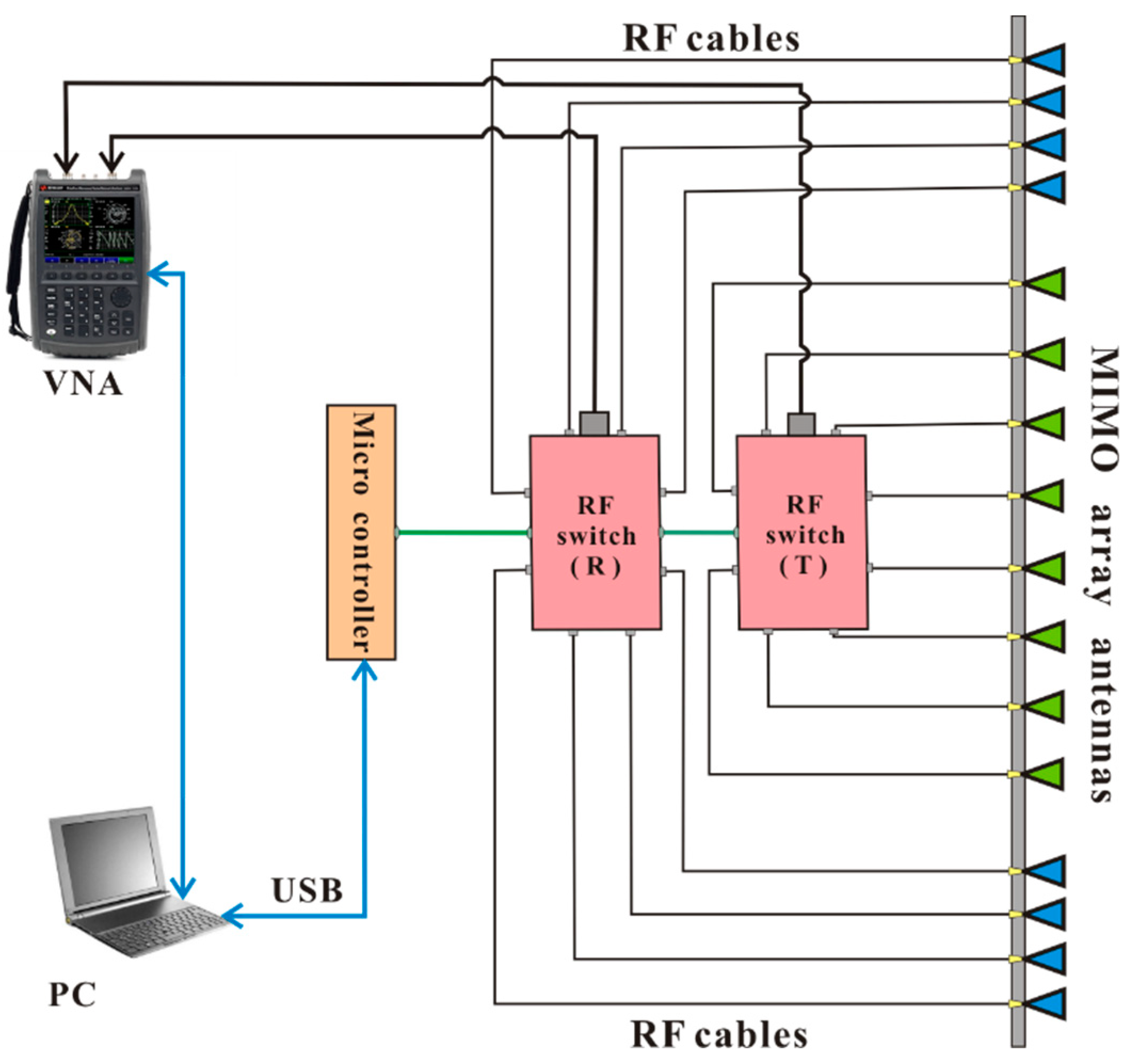
The block diagram of the designed UWB MIMO radar system is shown in Figure 1. The system includes: a PC, a two-port VNA (Agilent N9925A, working from 30 kHz to 9 GHz), two 1–8 radio frequency (RF) switchers with one microcontroller, a 16-Vivaldi-antenna MIMO array with about 1.1 m aperture. As the master controller, the PC connects the VNA and microcontroller. A set of RF cables and two switchers connect eight transmitting antennas and eight receiving antennas to the VNA. The eight transmitting antennas are fixed in the middle of the array, and the eight receiving antennas are separately fixed on the upper and lower sides of the array (shown in Figure 1).
The working principle of the designed radar system is briefly explained here: the VNA is responsible for sending and receiving SFCW signals. The PC is not only used to save and process the received data, but also to remotely operate the microcontroller and VNA. During one period of every S12 measurement by the VNA, only one pair of transmitting and receiving antennas collects data, corresponding to two paths of switcher system staying open and all other paths turning off. By switching on and off the switchers to control the data acquisition, the total amount of data obtained in one sampling period is 64 channels.
2.1. SFCW Signal Model and Conventional BP Algorithm
For the SFCW based radar system, the range resolution is determined by the frequency bandwidth. The UWB signal can be used to obtain higher range resolution with a low hardware requirement. Therefore, we utilize the UWB SFCW signal model in this paper.
Figure 2 shows a linear MIMO sparse array with an SFCW signal, which contains M transmitters and N receivers. Assuming the m-th transmitter and n-th receiver are located at (xm,0) and (xn,0), where and Given a point target located at (x0,y0), the average distance between the target and the l-th pair of transmitter and receiver (l-th sampling point) is given by
where .
Then, we assume that the whole imaging scene is discretized by I grids in the x axis and J grids in the y axis. There are a set of targets and each one is located at a given grid in the x-y coordinate. For the l-th sampling point and the q-th frequency the demodulated received signal can be expressed as
where kq = 2πfq/c is the wavenumber, Rl(xi,yi) is the average distance between the grid at (xi,yj) and the l-th sampling point; f0 is the start frequency, ∆f is the frequency step, α(xi,yj) is the reflection coefficient of target, c is the velocity of light, and n(l,q) is the noise.
The traditional BP algorithm is applied in the case of free space or uniform medium, and the target echo delay directly corresponds to the linear distance between the target and the antenna. One of the typical BP methods is the frequency-domain back projection (FDBP) method. It coherently sums the received signals from all the frequencies and sampling points to estimate the reflection coefficients of targets. With the received signal S(l,q), the reflection coefficient of a point (xi,yj) is estimated by
In practice, the time-domain implementation of BP method (TDBP) [9,20] is most commonly used in the highly suboptimal aperture length case for its simplicity. It can significantly save computing time. The formulation of TDBP can be written as
where
Equations (4) and (5) are the range compressed signal of the l-th sampling point, which can be easily obtained by the inverse fast Fourier transformation (IFFT) and interpolation process.
Although TDBP imaging methods are simple and convenient to implement, their imaging results may have high-level artifacts. Strong artifacts make weak targets undetectable and artifacts of many targets produce spurious peaks, leading to negative effects on 2D imaging. In order to effectively suppress artifacts, the cross-correlation-based TDBP (CC-TDBP) algorithm is applied [27,28], which can be expressed as
where and .
2.2. MIMO Array Topology Design
The design of the MIMO array is related to the complexity and cost of the radar system and directly affects the imaging quality. In designing MIMO array configurations, sparse array designs are often used to reduce system complexity and the number of antenna elements. In order to simplify the design of MIMO arrays, we first discuss the design factors from the following aspects.
Firstly, the azimuth resolution is determined by the aperture length of the array. Therefore, the azimuth resolution can be improved by properly increasing the aperture length of the array.
Secondly, after increasing the length of the array aperture, in order to satisfy the ideal imaging performance, the spacing and total number of antenna elements will also change. Specifically, due to the sparsity of the MIMO array, grating lobes and sidelobes may be generated in the imaging results, which seriously affect the quality of radar imaging. According to Nyquist sampling theory, the element spacing should be less than half of the radar wavelength in order to prevent unwanted grating lobes. On the other hand, with the decrease of the element spacing and the increase of the number of antennas, the direct coupling among the antennas will become stronger and high-level sidelobes will occur [29,30]. Therefore, considering the above factors, the antennas should keep a certain distance and the number of antennas should not be too large.
Finally, the imaging performance of UWB MIMO radar is related not only to the array configuration and number of elements, but also to the form of transmitted signals and application scenes. In this paper, a UWB SFCW signal is used to detect the short-range targets behind the wall. Therefore, it is necessary to consider the applicability of near-field conditions in through-wall detection. Generally, the longitudinal distance from the target to the MIMO array is much larger than the lateral distance between the target and the array elements. According to the verification results of [20,29,30,31,32], the focused SAR imaging and PSF results of MIMO sparse arrays and monostatic uniform arrays have almost the same performance in near-field conditions. Therefore, as for the MIMO through-wall radar system in this paper, the virtual array theory is applied to simplify the design and analysis of the MIMO sparse array.
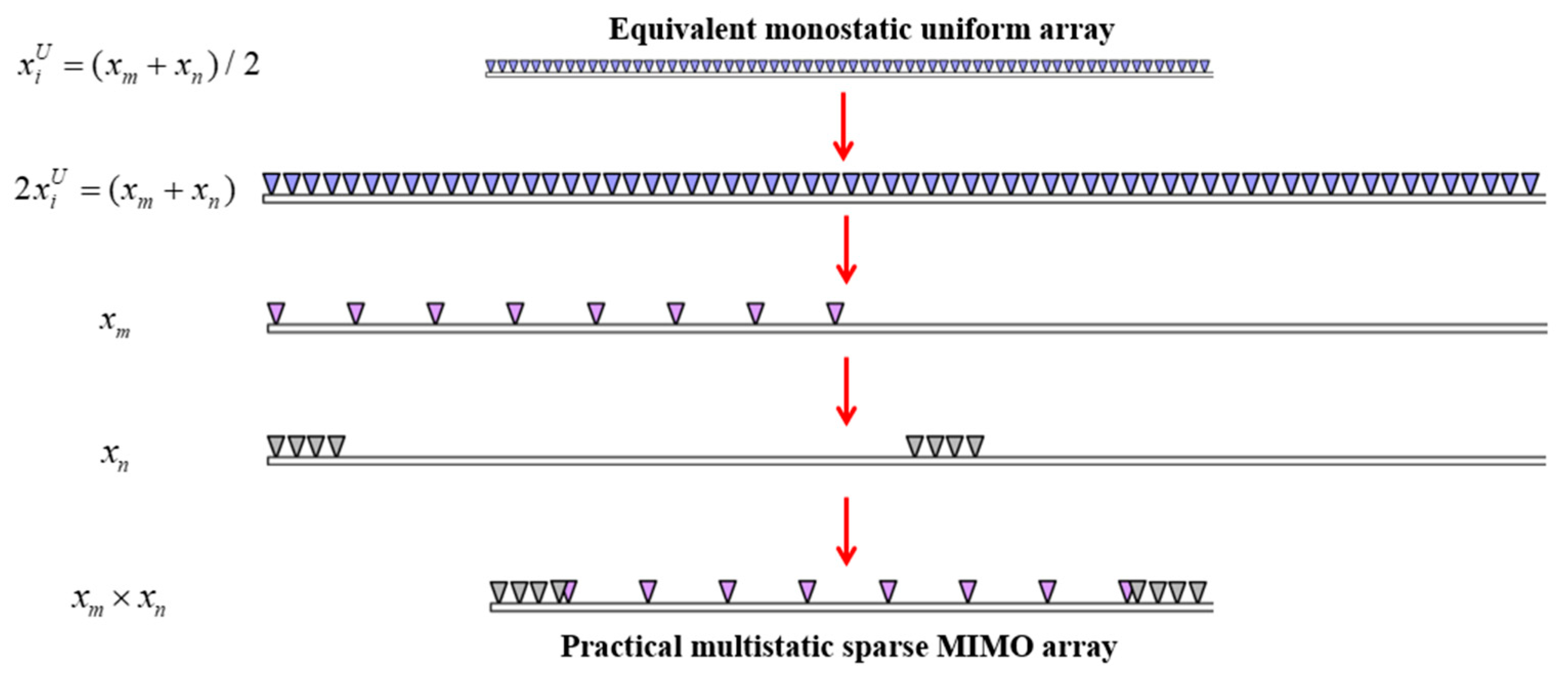
For a bistatic MIMO sparse array which contains M transmitters and N receivers, according to the theory of displaced phase center (DPC) approximation [18,33], two paths of the m-th transmitter at the xm-th position and the n-th receiver at xn-th position are switched on, while all the other paths are switched off. This is equivalent (in far field) to transmitting and receiving with one single ‘virtual’ antenna in the median position (xm + xn)/2 of the axis. The midpoints of each transmit and receive element are regarded as virtual elements for a linear equivalent monostatic array. Hence, for each combination of the m-th and n-th antennas, a specific pattern along the median axis is defined. As a result, we can first obtain an equivalent uniform array with MN (MN = M×N) monostatic transceivers, which has expected resolution and low-level grating/side lobes. Then, corresponding to the reverse thinking process mentioned above, the MIMO sparse array can be designed by factorization. In this case, a synthetic aperture imaging algorithm, such as the BP-based imaging algorithm, can be directly used to image the targets.
Based on the above analysis, the design steps of the MIMO array, which are illustrated in Figure 3, are as follows: Firstly, we begin with designing a linear monostatic uniform equivalent array. The effective aperture size L relative to the wavelength of the center frequency is determined by the required cross-range resolution , where λ is wavelength, L is equivalent uniform array length, and represents the potential distance of the target. Then, the required ideal sidelobe level (SL) is limited by the lower bound (dB) [21], which helps to derive the minimal number of the virtual elements K = MN required within the effective aperture, where K refers to the channels of the radar array. The next step is to determine the configuration of MIMO array, which is the factorization of a desired equivalent uniform array into topologies of transmitting and receiving MIMO arrays. The number of transmitting and receiving antennas can be obtained from the relation K = M × N (the total number of antenna elements is Num = M + N). The total number of antennas is minimized by selecting an equal or as close as possible number of elements in both transmitting and receiving arrays. For example, the number of virtual elements in the paper is 64; therefore, four different combinations of transmitting and receiving antenna element numbers can be obtained, which are: 1 × 64, 2 × 32, 4 × 16, and 8 × 8. The result with the minimal number of antennas is eight transmitters and eight receivers (8 × 8). At last, based on the polynomial factorization (PF) method in our previous research work [20], a MIMO array with eight pairs of transmitters and receivers was achieved, which satisfies the desired resolution and sidelobe level. The length of aperture is about 1.1 m. The operational center frequency is 1.5 GHz. The array possesses 6.8 cm range resolution and 5.8 rad azimuth resolution, with an equivalent aperture length of 1 m.
The designed MIMO array with 16 antennas can be used to collect 64 channels of raw data by switching on and off all antennas in a sampling period. This array design method can bring about great reduction in the total number of antenna elements and improve aperture efficiency while maintaining the aperture size. The topology of the designed MIMO array is shown in Figure 4. To assess the capacity of the designed MIMO array, given a point target located at (0,5), the point spread function (PSF) [20] of a sparse array in the azimuth direction is calculated, as given in Figure 5. We can see that the designed MIMO array can achieve low sidelobe level.
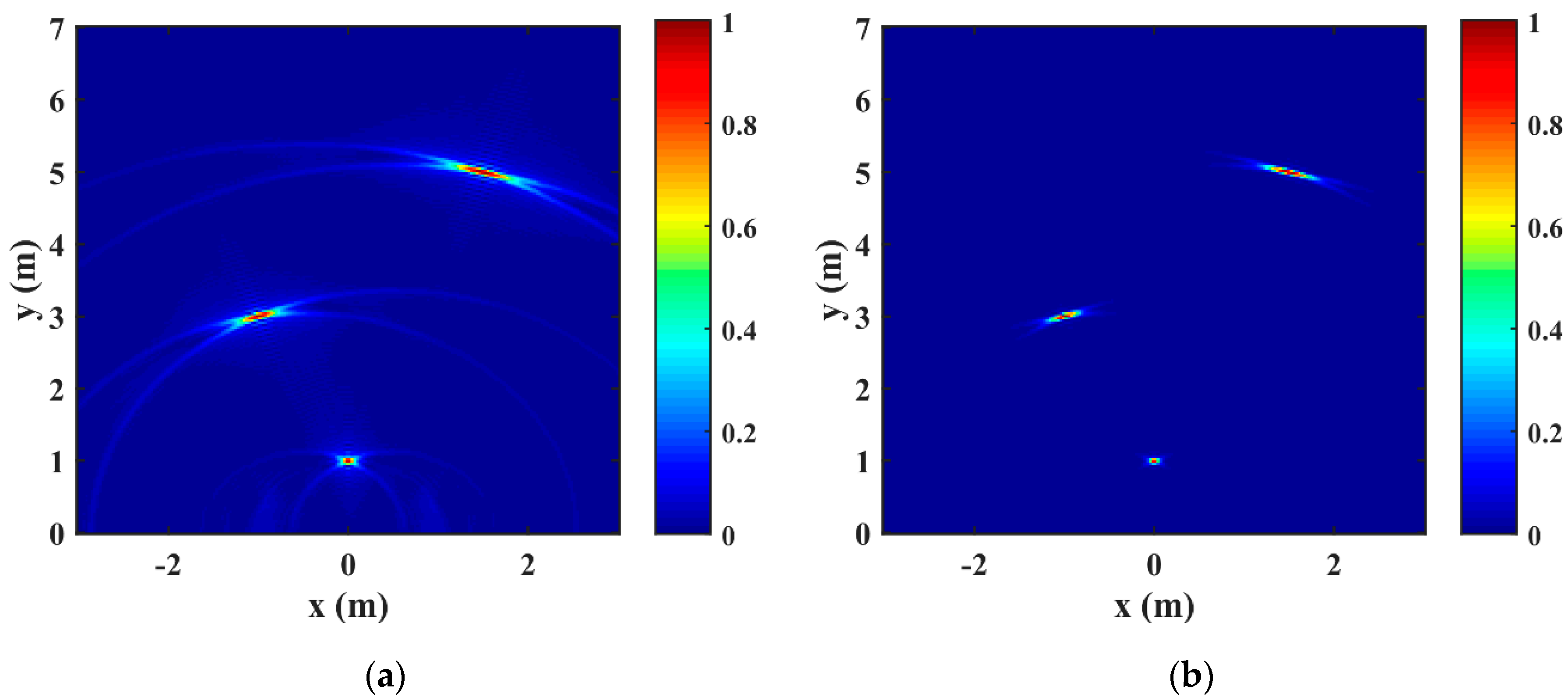
In order to assess the imaging quality of the above array design results and imaging methods, simple numerical simulations were carried out. The simulation parameters (Table 1) are consistent with the setting parameters of the actual system. Three targets located at different positions, which are (−1,3), (0,1) and (1.5,5), were simulated. Figure 6 shows the 2D imaging performance of the TDBP algorithm and the CC-TDBP algorithm from the designed layout of the MIMO array, respectively. It can be seen that the targets can be well focused. The artifacts in Figure 6b are suppressed compared with those in Figure 6a.
2.3. Low-Frequency UWB Miniaturized Vivaldi Antenna
The Vivaldi antenna is a kind of UWB tapered slot antenna. It has the advantages of wide bandwidth, symmetrical pattern, stable gain, simple structure, low profile, and easy integration [23,24]. Generally speaking, the size of antenna is determined by its working wavelength, and the wavelength λ can be obtained from the relationship () between the wave velocity c and frequency f in free space. Therefore, it can be clearly seen from the above relationship that the lower the operating frequency of the antenna, the larger the size of the antenna required. According to the needs of some specific applications, such as a portable MIMO antenna array for TWR imaging in this paper, we plan to use the UWB Vivaldi antenna with low frequency characteristics, so it is necessary to study the miniaturization of Vivaldi antenna. Through a series of studies and discussions [23,24,25,26,34,35,36], it can be concluded that most antenna sizes are reduced but many aspects of performance will be affected, such as narrowing of the working frequency band and decreasing of gain. As a result, the research on antenna miniaturization is to ensure that the performance of the antenna is minimally changed.
A miniaturization technique commonly used with Vivaldi antennas is to etch shorting slots with different shapes on the nonradiative sides of the metal patch [25,26,34,35]. Firstly, according to the structural analysis of the conventional tapered slot Vivaldi antenna, the radiation mechanism consists of current flowing effectively along the edge of the mid-tapered slot line and radiating outward. However, surface current and edge current also exist in the nonradiating metal areas on both sides of the antenna, which will affect the antenna gain and directivity. Then, some regular rectangle slots are etched on the nonradiative sides and the direction of the rectangle slot is perpendicular to the direction of the current. In this case, the flow path of the current is significantly increased. The rectangle slot edge structure on both sides of the antenna has infinite impedance for surface waves. It can effectively suppress the radiation of surface waves at the nonradiation sides so that the current flows along the mid-tapered slot line. As a result, the operating frequency of the antenna can be lowered without changing the size of the antenna and the operating mode.
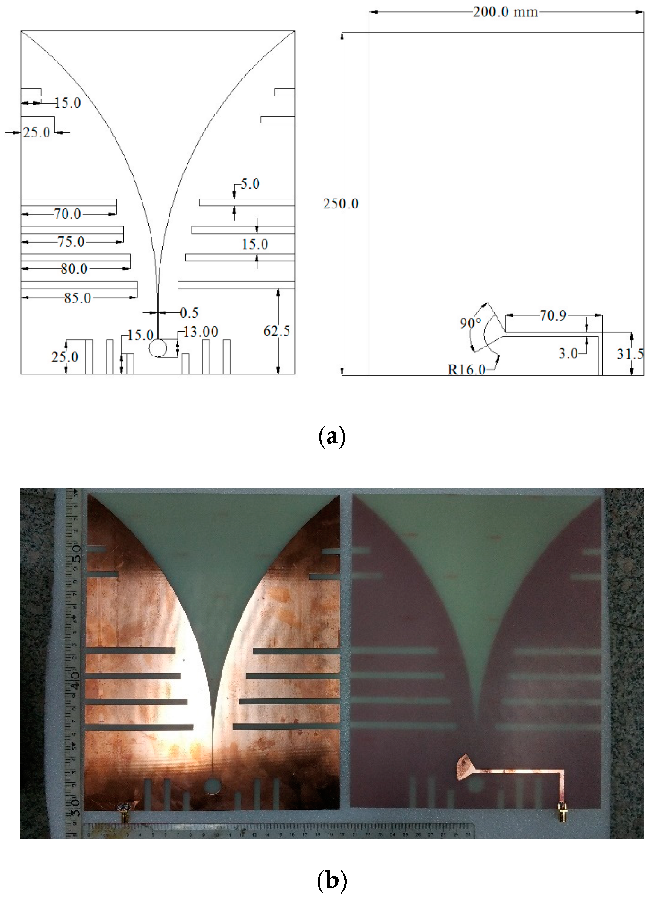
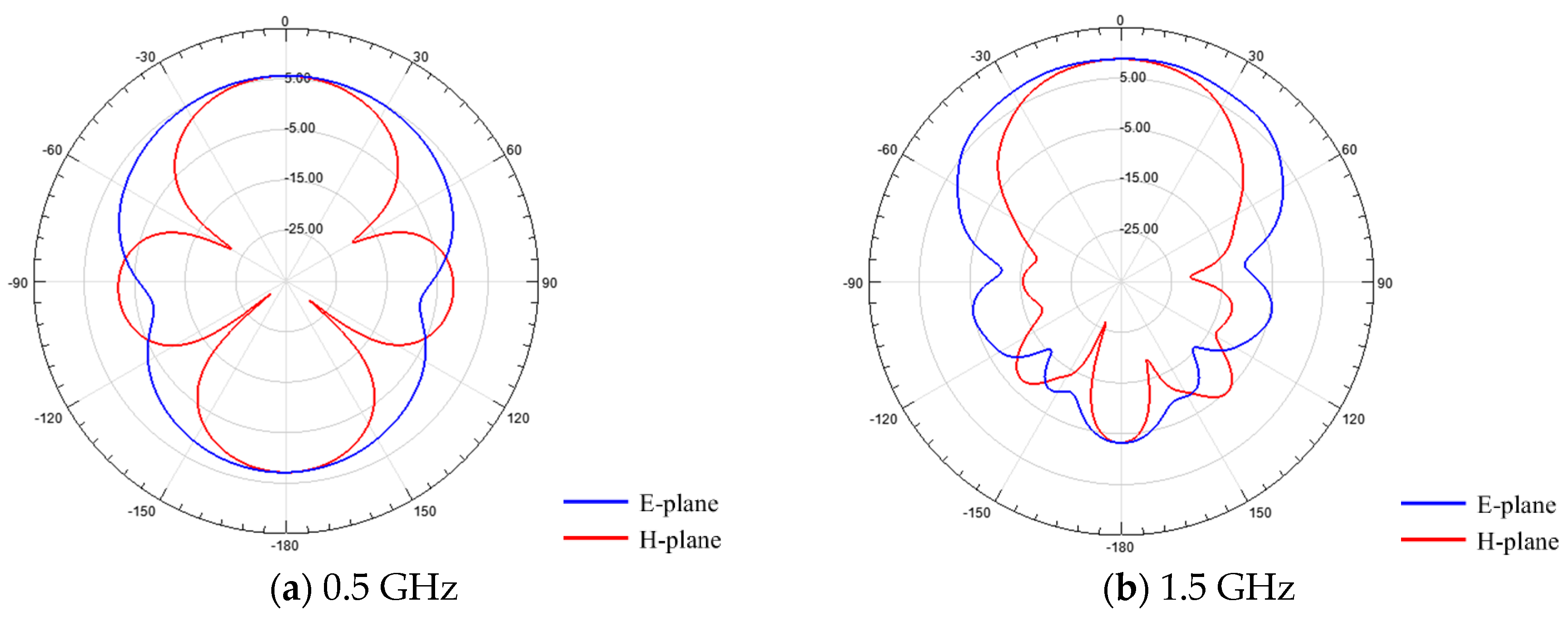
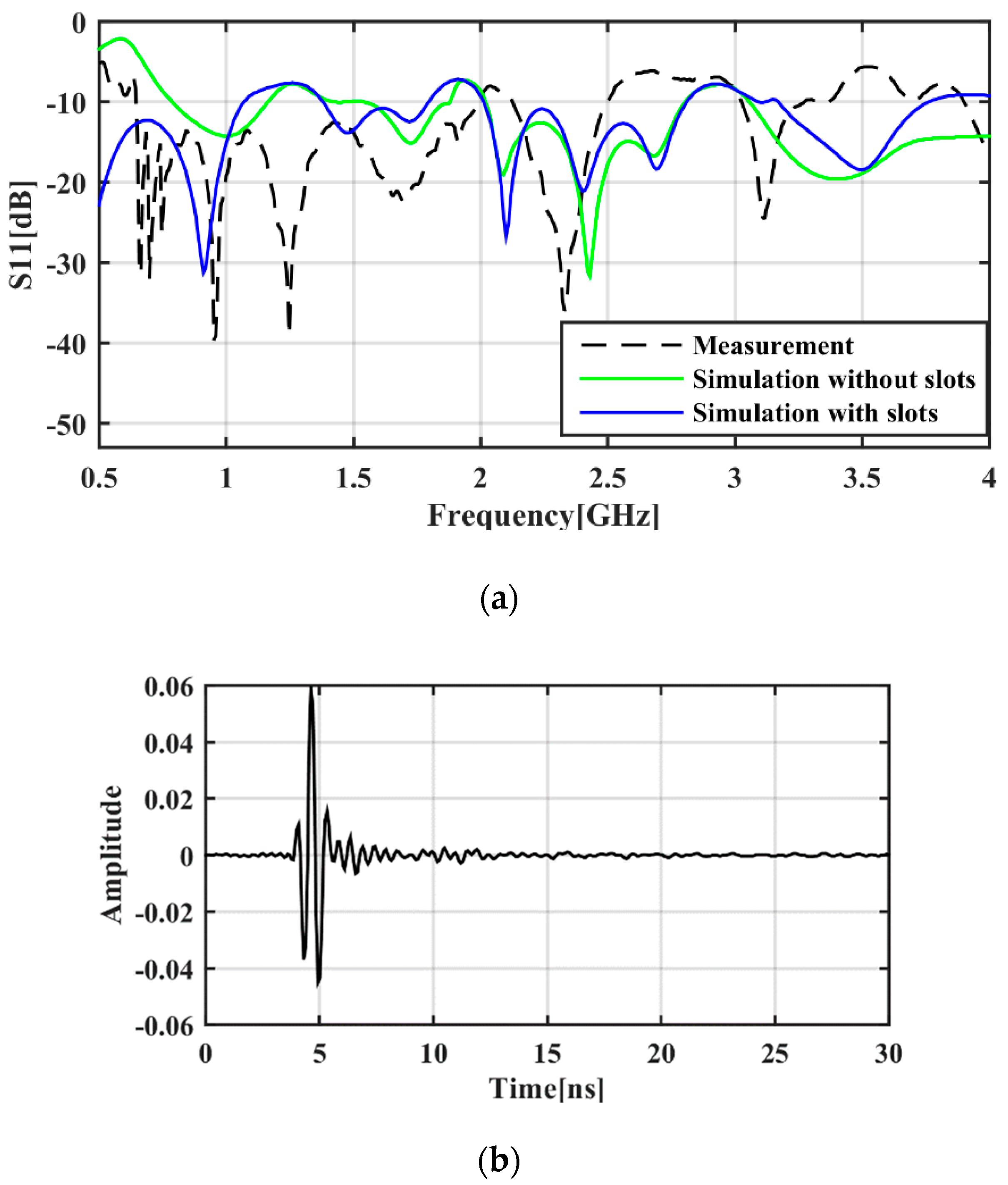
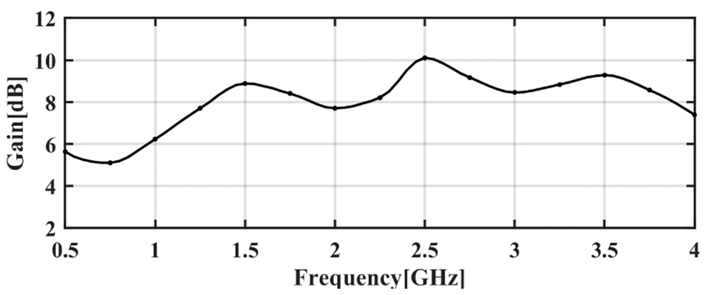
Above all, the final dimensions of optimized Vivaldi antenna structure in the results simulated by HFSS 15.0 are 250 mm × 200 mm × 1.6 mm, which is designed to work across the desired bandwidth of 0.5–2.5 GHz. Figure 7 shows the final design and fabrication result of the Vivaldi antenna. It is made of the low-cost FR4 substrate for which the dielectric constant is about 4.6. The feeding of the antenna is achieved by a subminiature version A (SMA) connector. Figure 8 plots both the E-plane and H-plane radiation patterns of the designed antenna at 0.5 GHz, 1.5 GHz, and 2.5 GHz, which are simulated using HFSS 15.0. It can be seen that the proposed Vivaldi antenna has good end fire radiation behavior and acceptable directivity in bandwidth of 0.5–2.5 GHz. Then, the antenna is measured by vector network analyzer (VNA) FieldFox N9925A. A comparison between the measured S11 with shorting slots and simulated S11 with and without shorting slots for the antenna is shown in Figure 9a. The −10 dB frequency bandwidth of 0.5–2.5 GHz is apparent. The measured result agrees well with the designed wideband except for the slight degradation of the low frequency starting band and the band near 2.0 GHz, where the S11 parameter rises to be a slightly higher than −10 dB. To see the tailing effect of the antennas for the time domain signal, we placed two identical Vivaldi antennas at the same altitude in parallel and face to face in the air, and then collected data once in the VNA’s S12 measurement mode. After simple IFFT processing, the single channel time domain wavelet is obtained. Figure 9b shows the one-channel wavelet pulse signal of the designed antenna in the time domain. Figure 10 shows the simulated total gain in the direction of the maximum radiation as a function of frequency for the designed Vivaldi antenna. We can see that the gain of the designed antenna increases as the frequency gets higher and it varies between 5.1 dB and 10.1 dB across the desired 0.5 to 2.5 GHz bandwidth. Compared with the UWB antennas for similar applications in [23], higher values of gain are provided in this paper (5–10 dB versus 2–7 dB).
2.4. Radar Prototyping Result
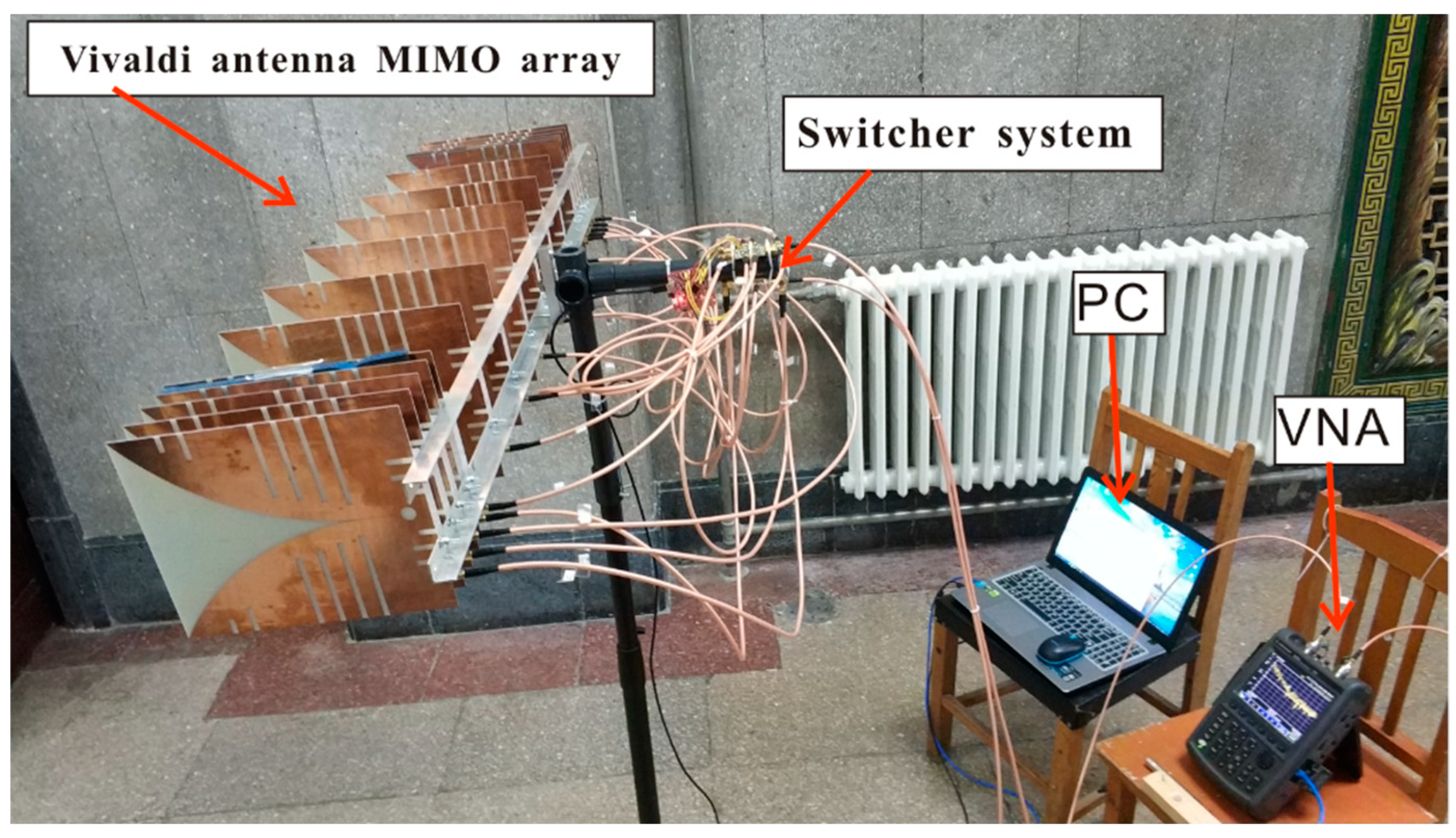
According to the above antenna design method, 16 identical Vivaldi antennas were fabricated. Then, the array was assembled by the proposed design method. All antenna elements were connected to each terminal of the RF switch through SMA connectors and RF cables. For the switch at the center frequency of 1.5 GHz, the insertion loss was about 1.8 dB, and the isolation was greater than 48 dB. The control and the synchronization of VNA and the RF switch were realized by a microcontroller with the help of the PC. Finally, a MIMO radar system for through-wall detection was manufactured. Corresponding to the radar design block diagram in Figure 1, Figure 11 displays the photography of the designed MIMO radar system.
The time delay and phase difference among the 64 (8 × 8) channels of the designed MIMO array radar system were compensated by using mechanical calibration of the VNA. To avoid further calibration procedures, all the paths between each antenna and the VNA were of the same EM length. Therefore, only one path required calibration. The designed parameters of the TWR system are given in Table 1.
3. Through-Wall Imaging Method with the Improved BP-Based Algorithm
The traditional cross-correlation based TDBP algorithm is simple and practical in free space. However, when considering the existence of a concrete wall with 22.5 cm thickness, the imaging results focused directly by the BP imaging algorithm will cause errors between the imaged positions and the true positions.
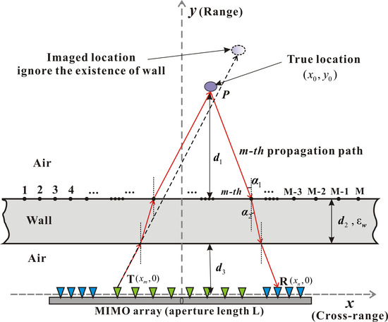
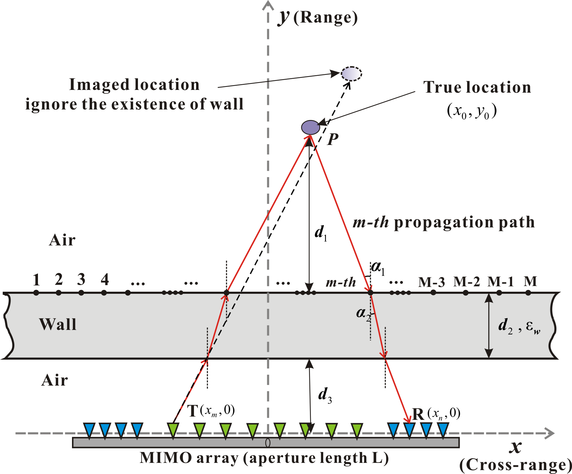
Generally speaking, the influence of the wall on the location of target imaging is mainly due to the following two reasons: firstly, the slow propagation of EM waves in the wall produce additional time delay. This causes the targets’ positions in the imaging results to be farther from than their actual positions. Secondly, the refraction and scattering of EM waves inside and outside the wall mean that the original propagation path is not a straight line. These errors are mainly affected by the relative dielectric constant of the wall. The above two points are briefly illustrated in Figure 12. In this paper, we propose an improved TDBP algorithm to reconstruct target locations behind the wall from MIMO sparse array radar data.
In the TDBP algorithm, the travel time for the wave field to propagate from the transmitter to the target and scatter back to the receiver must be known. In [37], we used ray tracing methods to efficiently calculate travel time in the TDBP algorithm for SIMO radar data. Assume that there are M paths passing through the wall from one antenna. The point p in the imaging area is a pixel on the m-th path. The incident angle is . The refraction angle is . The average propagation velocity of an EM wave inside the wall is . The relative dielectric constant of the wall is . The thickness of the wall is d2. The distance from the equivalent phase center of MIMO antenna array to the surface of the wall is d3. The distance from the point p to the wall is d1. According to Snell’s law, we can obtain
where .
The travel time from the one antenna to the point p is
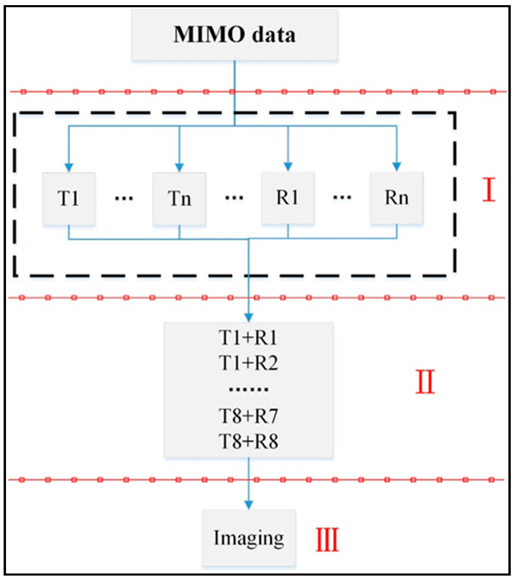
Then, the one-way travel time of all M propagation paths can be calculated in the same way, and the travel time of any point behind the wall can be obtained by interpolation from the M paths. The one-way travel time of any antenna can be computed similarly. Considering that there may be a large number of antennas in a MIMO array (16 in this paper), we designed a parallel algorithm on the MATLAB platform to improve the computational efficiency of one-way travel time (Figure 13, Part I). Assume the one-way travel time in the imaging area from the transmitter Tx1 is Tt1 and the receiver Rx1 is Tr1. For a pair of transmitting and receiving antennas, Tx1 and Rx1, the whole travel time behind the wall can be obtained by . According to the designed sparse MIMO array, we can obtain the whole travel time from all transmitters and receivers (at the pair of Tx1-Rx2, Rx3, … Rx8 to Tx8 − Rx8) to the imaging area behind the wall (Figure 13, Part II).
Finally, the TDBP algorithm can be directly applied to focus the data received from the MIMO antennas and reconstruct the target location (Figure 13, Part III). In this paper, M = 501 ray paths for every antenna are constructed, and the imaging range does not include the wall.
4. Experiment Results
In this section, three experiments are conducted to illustrate the performance and effectiveness of the designed MIMO radar system for 2D imaging. All parameters used in the experiments are the same as given in Table 1. The frequency range B of the radar system is 0.4–2.6 GHz, which results in the range resolution of = 6.8 cm. The number of frequencies is 256, which causes the unambiguous range to be 17.4 m. The S12 measurement mode for the Agilent N9925a VNA is selected. The imaging method is mainly based on the BP algorithm. In order to suppress the artifacts, the CC-TDBP method is also applied for comparison with the traditional TDBP algorithm. To make the target imaging clearer, background subtraction and direct coupling subtraction are also conducted for the real experimental data before applying the imaging algorithm. The direct coupling wave signal is obtained by collecting data while facing the MIMO array towards the open sky in an open area. Therefore, the received signal only contains the direct coupling component between the antenna elements. In general, the direct coupling data of one measurement result can be directly subtracted and applied to most 2D imaging of experimental scenes. The method of obtaining the background component is to measure the data without the real targets (human or corner reflector) in the experimental scene. Then, we can simply subtract the saved signal containing the background when we do the real measurement. This background removal method can eliminate the reflections of the wall, other stationary clutter, and the direct coupling between the antenna elements. It is relatively complicated and may be limited by the actual imaging situation. Because the background data are different for each specific imaging scene, the background data of each new experimental scene needs to be measured.
4.1. Preliminary Experimental Tests
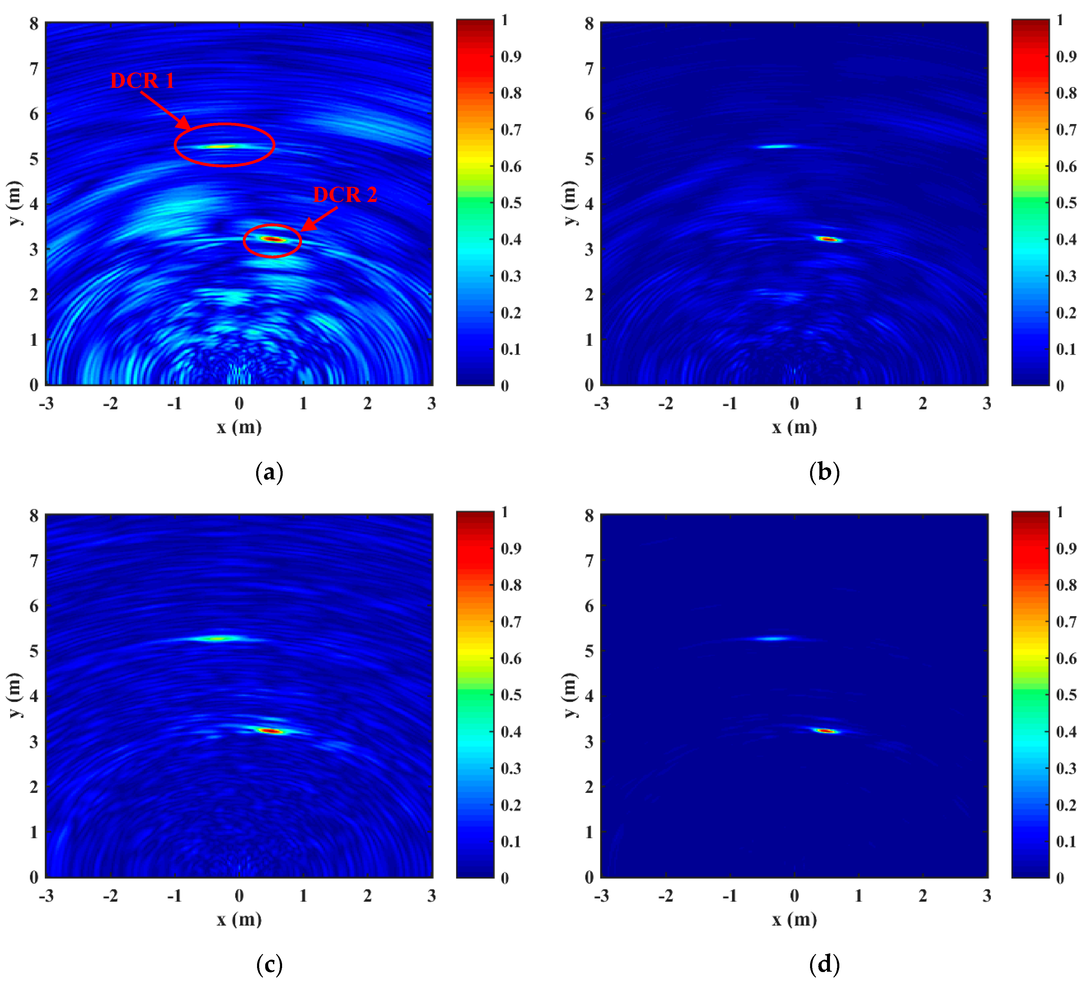
In order to test the actual target imaging ability of the designed MIMO radar system, the experiments were preliminarily carried out in the air. In the first experiment, two small dihedral corner reflectors (DCR) were used as the targets in an open space. The positions of the two dihedral corner reflectors were approximately about 3 m and 5 m away from the equivalent phase-center of the radar system. The experimental setup is shown in Figure 14 and the imaging results are shown in Figure 15. It can be observed that the two targets can be focused in 2D imaging. Compared to the results obtained by background removal (Figure 15c,d), it is obvious that the method of removing the presampled direct coupling (Figure 15a,b) is simple and can roughly distinguish the positions of the DCR targets. However, due to the influence of clutter signals, such as ground reflection, there are more noise points and artifacts in the direct coupling removed images. It is worth noting that after utilizing the CC-TDBP algorithm, the imaging results can further suppress the artifacts and clearly distinguish the exact locations of the DCR targets, no matter the methods of removing direct coupling or background, which are shown in Figure 15) and Figure 15d, respectively. In conclusion, the CC-TDBP algorithm can significantly improve image quality and suppress artifacts.
In the second experiment, to validate the human imaging performance of the designed radar system, two humans acted as targets in the near range, as shown in Figure 16. In this case, only the CC-TDBP algorithm was used, and the imaging results are shown in Figure 17. We can see that the two human targets marked by the red circle are clearly focused. In this preliminary experiment, even if the direct wave is removed (Figure 17a), the designed MIMO radar system can clearly detect the human targets in the air.
4.2. Through-Wall Experiment Results
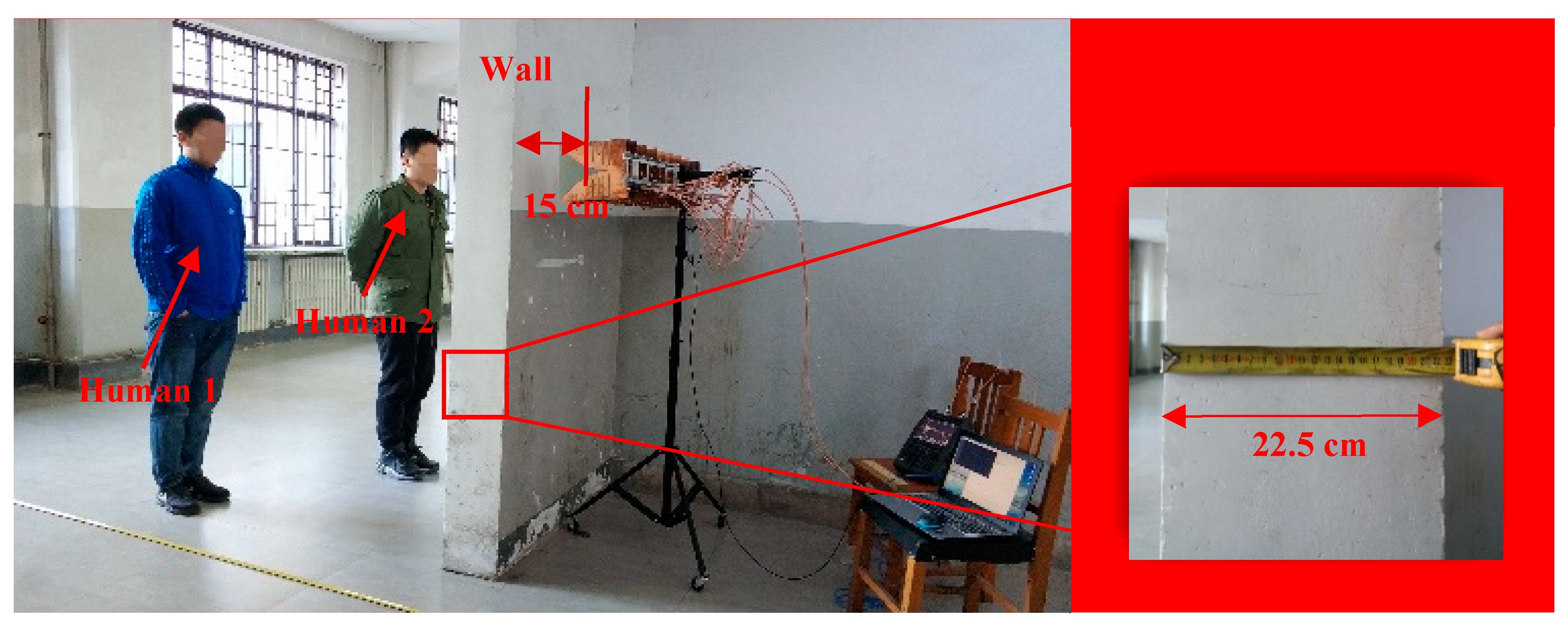
In the third experiment, to assess the through-wall performance of the designed MIMO radar system and the proposed improved BP algorithms, the scene consisted of two humans hidden behind a solid wall with thickness of 22.5 cm. The walls are made of brick and concrete. After preliminary measurement (a former reflection test on the wall was conducted, which estimated that the speed of electromagnetic waves is 0.137 m/ns, gives a dielectric constant of 4.795 for the wall), the relative dielectric constant of the wall is about 4.8. The experimental setup is shown in Figure 18. The MIMO array was placed parallel along the azimuth direction on the side of the wall. The equivalent phase center line of the array was measured about 15 cm away from the surface of the wall. The original point of the coordinate system of the imaging region was the midpoint of the equivalent phase center line.
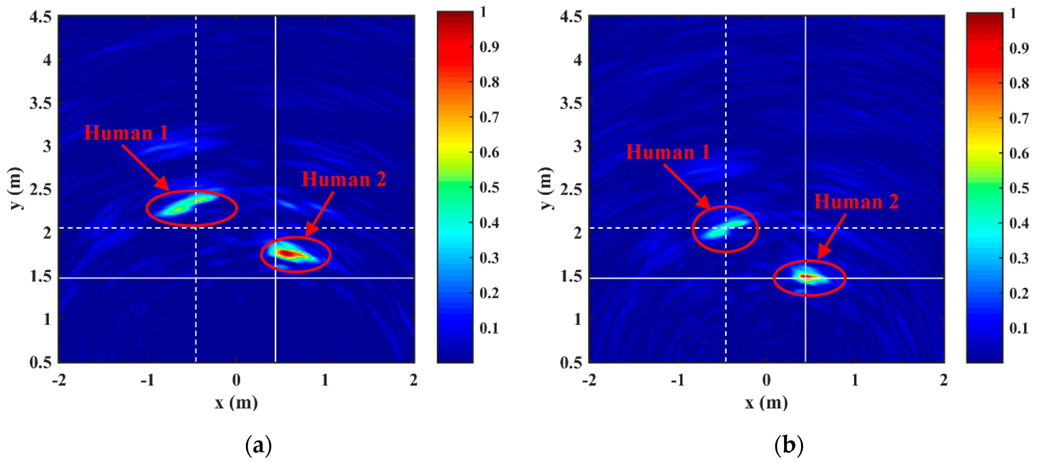
First of all, we directly utilized the CC-TDBP algorithm proposed in Section 2.1 to focus the echo data regardless of the wall effect. Background subtraction was applied to filter the reflections from the wall and the direct coupling among the antennas. It can be observed that the two targets in 2D imaging (Figure 19a) can be easily reconstructed and distinguished. The locations of the targets are marked by the red circle in Figure 19a, which verifies the imaging and detection performance of the designed MIMO radar system after the EM wave is attenuated due to the wall. However, it is worth noting that the wall effects, such as refraction dispersion and change of the EM wave speed, will impact the aforementioned data processing, generating an extra time delay and shifting of the targets. The intersection of white lines in Figure 19a is the real positions of the targets. It is obvious that the targets appear more distant compared to the intersection points.
Then, the improved BP imaging algorithm mentioned in Section 3 was applied, which considers the existence of the wall. The experimental result was improved and the corrected 2D imaging result is shown in Figure 19b. It can be observed that the positions of the targets in the image basically coincides with the intersection positions of the white lines. The reconstructed locations of the two human targets were much closer to the actual positions, which demonstrates the effectiveness of the improved BP algorithm for more accurate location of human targets behind the wall.
5. Discussion
In this paper, a linear sparse MIMO radar system which can be used for through-wall detection was designed and analyzed. The array design methods can reduce the number of antennas while maintaining the azimuth resolution. The traditional Vivaldi antenna was improved by antenna miniaturization technology, so that the characteristics of high gain, ultra-wideband, and low frequency were realized. This miniaturization approach may also be utilized to improve the bandwidth characteristics of other similar printed antennas. Concerning the imaging, the TDBP imaging algorithm based on cross correlation was presented in detail. The experimental results in Figure 15 and Figure 16 show that the proposed CC-TDBP algorithm can suppress artifacts better than the traditional TDBP algorithm. In addition, we considered the effect of the wall on the refraction of EM waves and the changes of velocity in the through-wall detection experiment (Section 4.2). Based on the principle of Snell’s law and ray tracing, a new through-wall imaging model is established in Figure 12. The improved BP algorithm with cross-correlation compensates for the wall’s influence and effectively focuses the targets behind the wall. Figure 19 shows that the targets’ locations are closer to the real positions measured by meter stick. Finally, the significance and characteristics of this research are discussed in the following four points.
(1). The direct significance of the MIMO radar system studied in this paper is to improve traditional synthetic aperture methods. The designed radar system with optimized UWB Vivaldi antennas has the characteristics of fast data acquisition speed, required azimuth resolution, low cost, and can be applied to through-wall detection. The Vivaldi antenna has been designed, simulated, manufactured, and successfully used in through-wall imaging, which is one of the contributions to the through-wall radar technology. The period data (64 channels data) acquisition time of the MIMO radar system is approximately 35 s. However, this relatively long sampling time is due to the specific VNA that operated as the transceiver. It is an old model (Agilent N9925a) which is not designed for fast acquisition. In fact, the MIMO radar does not have mechanical moving parts, so it can acquire data much faster than synthetic aperture radar (SAR) based on the movement of the transceiver along a rail [17]. In addition, compared with the current research [9,37] which is limited to simulation and validation, we developed the actual radar system to carry out experimental verification, which is more conducive to illustrate the effectiveness of the proposed system design and imaging algorithm.
(2). Generally, the dielectric constant of the wall is larger than that of the air. The transmitted EM waves have to pass the wall twice to reach the radar receivers, which further reduces the energy of the received target signal. In terms of amplitude attenuation, the first reflection from the front wall is the strongest and the higher-order reflection can be neglected. The signal information of the targets hidden behind walls, such as back walls and human targets, are mainly conveyed by the first transmission. It is worth noting that the reflection of the human body is relatively low compared with wall reflection and the direct coupling between the antennas. Moreover, the attenuation of the wall makes the collected human target signal weaker, which certainly increases the difficulty of through-wall imaging [38]. Therefore, in the third experiment, background removal is used to improve the imaging performance.
(3). Based on the VNA platform, the system is more flexible. For example, we can properly change the operating frequency range and frequency points of the system according to the specific application scenario. Thus, the range resolution and maximum ambiguity range can be improved. In particular, when the wall is thicker, the low-frequency UWB range can be chosen to improve the penetration of EM waves.
(4). As the detection distance increases, the energy received by the radar system will inevitably be attenuated. As shown in Figure 15 and Figure 19, when multiple targets are distributed at different distances in the imaging scene, the relatively weak energy of distant targets may be concealed in clutter. Therefore, we still need to study an effective way to solve this problem, such as adding amplifiers or shielding devices to the radar system to improve energy in the next step.
In future research, the application of MIMO through-wall radar to extract vital signs (such as breathing, heartbeat, arm swing) or human micro-Doppler [39,40] will be explored. In addition, compressive sensing technology can also be applied to through-wall detection of sparse arrays to reduce the sampling time and improve the resolution [41]. Moreover, it is worth mentioning that the existence of multiple walls, the detection of moving targets, real-time positioning imaging, and even three-dimensional imaging will also be challenging research tasks in our future work.
6. Conclusions
This paper develops a UWB MIMO radar system for through-wall imaging by the cross-correlation-based TDBP algorithm. Low-frequency UWB miniaturized Vivaldi antennas were designed and realized to ensure good system performance of wall penetration. The designed antenna, which is one of this paper’s contributions, has acceptable through-wall imaging performance and is small in size, low in cost, and easy to manufacture. The system’s working frequency is from 0.4 GHz to 2.6 GHz, conferring a range resolution of 6.8 cm. The aperture length of the designed MIMO array is about 1.1 m, resulting in an angle resolution of 5.8 rad. It is worth noting that the wall effects, such as refraction dispersion and change of the EM wave speed, are not ignored for the data processing. The through-wall imaging model is proposed and human targets were reconstructed more accurately in through-wall experiments. The results of the experiments demonstrate that, both in range and azimuth direction, the proposed imaging methods can effectively suppress artifacts and focus the different targets, and the designed MIMO radar system can detect and localize human targets behind a wall.
Author Contributions
Writing—original draft preparation, Z.H.; writing—review and editing, Z.H. and Z.Z.; methodology, Z.H., W.F. and K.W.; hardware design, Z.H., X.K. and W.F.; software, Z.H., W.F. and K.W.; validation, Z.H., J.Z. and Q.L.; formal analysis, Z.H., J.Z. and X.K.; data curation, Z.H., W.F. and K.W.; supervision, Q.L., Z.Z.; project administration, Z.Z.; funding acquisition, Z.Z.
Funding
This research was supported by the Natural Science Foundation of China (41174097, 41574097) and the Provincial School Construction Project of Jilin Province (SXGJSF 2017-5).
Acknowledgments
Zhipeng Hu is grateful to Tohoku University and Motoyuki Sato for a three-month visiting to Center for Northeast Asian Studies (CNEAS).
Conflicts of Interest
The authors declare no conflict of interest.
References
- Amin, M.G. Through-the-Wall Radar Imaging; CRC Press: London, UK, 2011. [Google Scholar]
- Baranoski, E.J. Through-wall imaging: Historical perspective and future directions. J. Frankl. Inst. 2008, 345, 556–569. [Google Scholar] [CrossRef]
- Lan, F.; Kong, L.; Yang, X.; Jia, Y.; Ke, X. Life-sign detection of through-wall-radar based on fourth-order cumulant. In Proceedings of the 2013 IEEE Radar Conference, Ottawa, ON, Canada, 29 April–3 May 2013. [Google Scholar]
- Amin, M.G. Radar, signal, and image processing techniques for through the wall imaging. In Proceedings of the Digital Wireless Communications VII and Space Communication Technologies, Orlando, FL, USA, 2 June 2005. [Google Scholar]
- Nikolic, M.M.; Nehorai, A.; Djordjevic, A.R. Estimating moving targets behind reinforced walls using radar. IEEE Trans. Antennas Propag. 2009, 57, 3530–3538. [Google Scholar] [CrossRef]
- Yılmaz, B.; Özdemir, C. Design and prototype of radar sensor with Vivaldi linear array for through-wall radar imaging: An experimental study. J. Appl. Remote Sens. 2016, 10, 046012. [Google Scholar] [CrossRef]
- Ralston, T.S.; Charvat, G.L.; Peabody, J.E. Real-time through-wall imaging using an ultrawideband multiple-input multiple-output (MIMO) phased array radar system. In Proceedings of the 2010 IEEE international symposium on phased array systems and technology, Waltham, MA, USA, 12–15 October 2010. [Google Scholar]
- Guo, S.; Cui, G.; Kong, L.; Song, Y.; Yang, X. Multipath Analysis and Exploitation for MIMO Through-the-Wall Imaging Radar. IEEE J. Sel. Top. Appl. Earth Observ. Remote Sens. 2018, 11, 3721–3731. [Google Scholar] [CrossRef]
- Wang, M.; Cui, G.; Yi, W.; Kong, L.; Yang, X.; Yuan, L. Time-division MIMO through-the-wall radar imaging behind multiple walls. In Proceedings of the 2015 IEEE Radar Conference, Arlington, VA, USA, 10–15 May 2015. [Google Scholar]
- Dehmollaian, M.; Thiel, M.; Sarabandi, K. Through-the-wall imaging using differential SAR. IEEE Trans. Geosci. Remote Sens. 2009, 47, 1289–1296. [Google Scholar] [CrossRef]
- Laviada, J.; Arboleya, A.; López-Gayarre, F.; Las-Heras, F. Broadband synthetic aperture scanning system for three-dimensional through-the-wall inspection. IEEE Geosci. Remote Sens. Lett. 2015, 13, 97–101. [Google Scholar] [CrossRef]
- Yang, J.; Thompson, J.; Huang, X.; Jin, T.; Zhou, Z. Random-frequency SAR imaging based on compressed sensing. IEEE Trans. Geosci. Remote Sens. 2013, 51, 983–994. [Google Scholar] [CrossRef]
- Jin, T.; Chen, B.; Zhou, Z. Image-domain estimation of wall parameters for autofocusing of through-the-wall SAR imagery. IEEE Trans. Geosci. Remote Sens. 2013, 51, 1836–1843. [Google Scholar] [CrossRef]
- Bliss, D.W.; Forsythe, K.W. Multiple-input multiple-output (MIMO) radar and imaging: Degrees of freedom and resolution. In Proceedings of the Thrity-Seventh Asilomar Conference on Signals, Systems & Computers, Pacific Grove, CA, USA, 9–12 November 2003. [Google Scholar]
- Fishler, E.; Haimovich, A.; Blum, R.; Chizhik, D.; Cimini, L.; Valenzuela, R. MIMO radar: An idea whose time has come. In Proceedings of the 2004 IEEE radar conference, Philadelphia, PA, USA, 29 April 2004. [Google Scholar]
- Narayanan, R.M.; Gebhardt, E.T.; Broderick, S.P. Through-Wall Single and Multiple Target Imaging Using MIMO Radar. Electronics 2017, 6, 70. [Google Scholar] [CrossRef]
- Pieraccini, M.; Miccinesi, L. An Interferometric MIMO Radar for Bridge Monitoring. IEEE Geosci. Remote Sens. Lett. 2019, 1–5. [Google Scholar] [CrossRef]
- Zhuge, X.; Yarovoy, A.G. Sparse multiple-input multiple-output arrays for high-resolution near-field ultra-wideband imaging. IET Microw. Antennas Propag. 2011, 5, 1552–1562. [Google Scholar] [CrossRef]
- Zhuge, X. Short-Range Ultra-Wideband Imaging with Multiple-Input Multiple-Output Arrays. Ph.D. Thesis, Delft University Technology (TUDelft), Delft, The Netherlands, 2010. [Google Scholar]
- Feng, W.; Zou, L.; Sato, M. 2D imaging by sparse array radar system. IEICE Tech. Rep. 2016, 116, 65–70. [Google Scholar]
- Schwartz, J.L.; Steinberg, B.D. Ultrasparse, ultrawideband arrays. IEEE Trans. Ultrason. Ferroelectr. Freq. Control 1998, 45, 376–393. [Google Scholar] [CrossRef] [PubMed]
- Maaref, N.; Millot, P. Array-based UWB FMCW through-the-wall radar. In Proceedings of the 2012 IEEE International Symposium on Antennas and Propagation, Chicago, IL, USA, 8–14 July 2012. [Google Scholar]
- Fioranelli, F.; Salous, S.; Ndip, I.; Raimundo, X. Through-the-wall detection with gated FMCW signals using optimized patch-like and Vivaldi antennas. IEEE Trans. Antennas Propag. 2015, 63, 1106–1117. [Google Scholar] [CrossRef]
- Gibson, P.J. The vivaldi aerial. In Proceedings of the 1979 9th European Microwave Conference, Brighton, UK, 17–20 September 1979. [Google Scholar]
- Fei, P.; Jiao, Y.C.; Hu, W.; Zhang, F.S. A miniaturized antipodal Vivaldi antenna with improved radiation characteristics. IEEE Antennas Wirel. Propag. Lett. 2011, 10, 127–130. [Google Scholar]
- Rizk, J.B.; Rebeiz, G.M. Millimeter-wave Fermi tapered slot antennas on micromachined silicon substrates. IEEE Trans. Antennas Propag. 2002, 50, 379–383. [Google Scholar] [CrossRef]
- Feng, W.; Yi, L.; Sato, M. Near range radar imaging based on block sparsity and cross-correlation fusion algorithm. IEEE J. Sel. Top. Appl. Earth Observ. Remote Sens. 2018, 11, 2079–2089. [Google Scholar] [CrossRef]
- Zhou, L.; Huang, C.; Su, Y. A fast back-projection algorithm based on cross correlation for GPR imaging. IEEE Geosci. Remote Sens. Lett. 2012, 9, 228–232. [Google Scholar] [CrossRef]
- Gumbmann, F.; Tran, P.; Schmidt, L.P. Sparse linear array design for a short range imaging radar. In Proceedings of the 2009 European Radar Conference, Rome, Italy, 30 September–2 October 2009. [Google Scholar]
- Ge, T.; Zhao, L.; Cai, Y.; Zhou, J. A grating lobes suppression technique for near-field sparse linear MIMO array imaging. In Proceedings of the 2016 CIE International Conference on Radar, Guangzhou, China, 10–13 October 2016. [Google Scholar]
- Jin, L.; Ouyang, S.; Zhou, L. Array design and imaging method for ultra-wideband multiple-input multiple-output through-the-wall radar. J. Electron. Inf. Technol. 2012, 34, 1574–1580. (In Chinese) [Google Scholar] [CrossRef]
- Fishler, E.; Haimovich, A.; Blum, R.; Cimini, L.; Chizhik, D.; Valenzuela, R. Spatial diversity in radars-models and detection performance. IEEE Trans. Signal Process. 2006, 54, 823–838. [Google Scholar] [CrossRef]
- Bellettini, A.; Pinto, M.A. Theoretical accuracy of synthetic aperture sonar micronavigation using a displaced phase-center antenna. IEEE J. Ocean. Eng. 2002, 27, 780–789. [Google Scholar] [CrossRef]
- Teni, G.; Zhang, N.; Qiu, J.; Zhang, P. Research on a novel miniaturized antipodal Vivaldi antenna with improved radiation. IEEE Antennas Wirel. Propag. Lett. 2013, 12, 417–420. [Google Scholar] [CrossRef]
- Guo, Z.; Yang, S.; Shi, Z.; Chen, Y. A miniaturized wideband dual-polarized linear array with balanced antipodal Vivaldi antenna. In Proceedings of the 2016 IEEE MTT-S International Microwave Workshop Series on Advanced Materials and Processes for RF and THz Applications (IMWS-AMP), Chengdu, China, 20–22 July 2016. [Google Scholar]
- Yang, Y.; Wang, Y.; Fathy, A.E. Design of compact Vivaldi antenna arrays for UWB see through wall applications. Prog. Electromagn. Res. 2008, 82, 401–418. [Google Scholar] [CrossRef]
- Wang, K.; Zeng, Z.; Sun, J. Through-Wall Detection of the Moving Paths and Vital Signs of Human Beings. IEEE Geosci. Remote Sens. Lett. 2018, 16, 717–721. [Google Scholar] [CrossRef]
- Song, Y.; Hu, J.; Chu, N.; Jin, T.; Zhang, J.; Zhou, Z. Building Layout Reconstruction in Concealed Human Target Sensing via UWB MIMO Through-Wall Imaging Radar. IEEE Geosci. Remote Sens. Lett. 2018, 15, 1199–1203. [Google Scholar]
- Qi, F.; Liang, F.; Lv, H.; Li, C.; Chen, F.; Wang, J. Detection and Classification of Finer-Grained Human Activities Based on Stepped-Frequency Continuous-Wave Through-Wall Radar. Sensors 2016, 16, 885. [Google Scholar] [CrossRef] [PubMed]
- Gennarelli, G.; Ludeno, G.; Soldovieri, F. Real-Time Through-Wall Situation Awareness Using a Microwave Doppler Radar Sensor. Remote Sens. 2016, 8, 621. [Google Scholar] [CrossRef]
- Ma, Y.; Hong, H.; Zhu, X. Interaction Multipath in Through-the-Wall Radar Imaging Based on Compressive Sensing. Sensors 2018, 18, 549. [Google Scholar] [Green Version]
Figure 1.
Block diagram of the designed ultra-wideband multi-input multi-output (UWB MIMO) radar system.
Figure 1.
Block diagram of the designed ultra-wideband multi-input multi-output (UWB MIMO) radar system.

Figure 2.
The signal model of the UWB SFCW radar with a MIMO array.

Figure 3.
Schematic diagram of the polynomial factorization (PF) method.

Figure 4.
Topology of the designed MIMO sparse array.

Figure 5.
Point spread function (PSF) of the designed MIMO sparse array in the azimuth direction.

Figure 6.
Simulations for the MIMO sparse array by: (a) the time domain back projection (TDBP) algorithm; (b) the cross-correlation-based time domain back projection (CC-TDBP) algorithm.
Figure 6.
Simulations for the MIMO sparse array by: (a) the time domain back projection (TDBP) algorithm; (b) the cross-correlation-based time domain back projection (CC-TDBP) algorithm.

Figure 7.
(a) Configurations of the designed Vivaldi antenna; (b) Top and bottom view of the manufactured Vivaldi antenna.
Figure 7.
(a) Configurations of the designed Vivaldi antenna; (b) Top and bottom view of the manufactured Vivaldi antenna.

Figure 8.
Simulated E-plane and H-plane radiation patterns of the designed Vivaldi antenna. (a) 0.5 GHz, (b) 1.5 GHz, and (c) 2.5 GHz.
Figure 8.
Simulated E-plane and H-plane radiation patterns of the designed Vivaldi antenna. (a) 0.5 GHz, (b) 1.5 GHz, and (c) 2.5 GHz.


Figure 9.
(a) The measured S11 of designed Vivaldi antenna with shorting slots and the simulated S11 of the proposed Vivaldi antenna with and without shorting slots; (b) The measured result of S12 in time domain of the designed Vivaldi antenna with slots.
Figure 9.
(a) The measured S11 of designed Vivaldi antenna with shorting slots and the simulated S11 of the proposed Vivaldi antenna with and without shorting slots; (b) The measured result of S12 in time domain of the designed Vivaldi antenna with slots.

Figure 10.
Total gain as a function of frequency of the designed Vivaldi antenna.

Figure 11.
Photograph of designed MIMO radar prototype.

Figure 12.
Imaging geometry for through-wall radar (TWR) with the designed MIMO array.

Figure 13.
Flow chart of the improved TDBP algorithm. Part I: One-way travel time calculation based on the parallel algorithm; Part II: the whole travel time for the MIMO sparse array; Part III: TDBP imaging.
Figure 13.
Flow chart of the improved TDBP algorithm. Part I: One-way travel time calculation based on the parallel algorithm; Part II: the whole travel time for the MIMO sparse array; Part III: TDBP imaging.

Figure 14.
Experiment setup for dihedral corner reflector imaging.

Figure 15.
Imaging results of two corner reflectors by: (a) the TDBP algorithm with direct coupling removal; (b) the CC-TDBP algorithm with direct coupling removal; (c) the TDBP algorithm with background removal; (d) the CC-TDBP algorithm with background removal.
Figure 15.
Imaging results of two corner reflectors by: (a) the TDBP algorithm with direct coupling removal; (b) the CC-TDBP algorithm with direct coupling removal; (c) the TDBP algorithm with background removal; (d) the CC-TDBP algorithm with background removal.

Figure 16.
Experiment setup for human imaging.

Figure 17.
Imaging results obtained by the CC-TDBP algorithm with: (a) direct coupling removal; (b) background removal.
Figure 17.
Imaging results obtained by the CC-TDBP algorithm with: (a) direct coupling removal; (b) background removal.

Figure 18.
Experimental setup for the through-wall scene.

Figure 19.
2D through-wall imaging results for two humans behind a wall: (a) Imaging directly by the CC-TDBP algorithm with background removal; (b) Imaging by improved the CC-TDBP algorithm considering the presence of the wall.
Figure 19.
2D through-wall imaging results for two humans behind a wall: (a) Imaging directly by the CC-TDBP algorithm with background removal; (b) Imaging by improved the CC-TDBP algorithm considering the presence of the wall.


Table 1.
System parameters.
| Parameters | Value |
|---|---|
| Start frequency | 0.4 GHz |
| Stop frequency | 2.6 GHz |
| Number of frequencies | 256 |
| Number of transmitters/receivers | 8/8 |
| Range resolution | 0.068 m |
| Azimuth resolution | 5.8 rad |
| Maximum range | 17.4 m |
| Length of aperture | 1.1 m |
© 2019 by the authors. Licensee MDPI, Basel, Switzerland. This article is an open access article distributed under the terms and conditions of the Creative Commons Attribution (CC BY) license (http://creativecommons.org/licenses/by/4.0/).
Share and Cite
MDPI and ACS Style
Hu, Z.; Zeng, Z.; Wang, K.; Feng, W.; Zhang, J.; Lu, Q.; Kang, X. Design and Analysis of a UWB MIMO Radar System with Miniaturized Vivaldi Antenna for Through-Wall Imaging. Remote Sens. 2019, 11, 1867. https://doi.org/10.3390/rs11161867
AMA Style
Hu Z, Zeng Z, Wang K, Feng W, Zhang J, Lu Q, Kang X. Design and Analysis of a UWB MIMO Radar System with Miniaturized Vivaldi Antenna for Through-Wall Imaging. Remote Sensing. 2019; 11(16):1867. https://doi.org/10.3390/rs11161867
Chicago/Turabian StyleHu, Zhipeng, Zhaofa Zeng, Kun Wang, Weike Feng, Jianmin Zhang, Qi Lu, and Xiaoqian Kang. 2019. "Design and Analysis of a UWB MIMO Radar System with Miniaturized Vivaldi Antenna for Through-Wall Imaging" Remote Sensing 11, no. 16: 1867. https://doi.org/10.3390/rs11161867
Note that from the first issue of 2016, this journal uses article numbers instead of page numbers. See further details here.