Article

Charting Dynamic Areas in the Mackenzie River with RADARSAT-2, Simulated RADARSAT Constellation Mission and Optical Remote Sensing Data

Canadian Hydrographic Service, 200 Kent Street, Ottawa, ON K1A 0E6, Canada
*
Author to whom correspondence should be addressed.
Remote Sens. 2019, 11(13), 1523; https://doi.org/10.3390/rs11131523
Submission received: 25 April 2019 / Revised: 18 June 2019 / Accepted: 25 June 2019 / Published: 27 June 2019

Abstract

:
Mariners navigating within Canadian waters rely on Canadian Hydrographic Service (CHS) navigational charts to safely reach their destinations. To fulfil this need, CHS charts must accurately reflect the current state of Canadian coastal regions. While many coastal regions are stable, others are dynamic and require frequent updates. In order to ensure that important and potentially dangerous changes are reflected in CHS products, the organization, in partnership with the Canadian Space Agency, is exploring coastal change detection through satellite remote sensing (SRS). In this work, CHS examined a hybrid shoreline extraction approach which uses both Synthetic Aperture Radar (SAR) and optical data. The approach was applied for a section of the Mackenzie River, one of Canada’s most dynamic river systems. The approach used RADARSAT-2 imagery as its primary information source, due to its high positioning accuracy (5 m horizontal accuracy) and ability to allow for low and high water line charting. Landsat represented the primary optical data source due to its long historical record of Earth observation data. Additional sensors, such as Sentinel-2 and WorldView, were also used where a higher resolution was required. The shoreline extraction process is based on an image segmentation approach that uses both the radar and optical data. Critical information was collected using the automated approach to support chart updates, resulting in reductions to the financial, human and time factors present within the ship-based hydrographic survey techniques traditionally used for chart improvements. The results demonstrate the potential benefit of wide area SRS change detection within dynamic waterways for navigational chart improvements. The work also demonstrates that the approach developed for RADARSAT-2 could be implemented with data from the forthcoming RADARSAT Constellation Mission (RCM), which is critical to ensure project continuity.

Graphical Abstract

1. Introduction

In order to ensure safe navigation in Canadian waters, the Canadian Hydrographic Service (CHS) produces and maintains close to 1000 nautical charts along with other hydrographic products. Traditionally, bathymetric data has been, and still is largely acquired from ship-based surveys, collected using multi-beam echo-sounders. Other data presented on hydrographic charts, such as shorelines and intertidal zones, are manually digitized using aerial photography, and more recently with high resolution satellite imagery. These methods, particularly manually digitizing field surveys, require investments in resources to complete, and only cover a small portion of Canadian waters and shorelines. Furthermore, while some areas in Canadian waters are static and have a low rate of change, other areas are very dynamic. The latter may exhibit changes over several years, months or even days. In order to improve the representation of dynamic areas on CHS products and thus improve mariner safety, new approaches must be developed.
One example of a dynamic area is the Mackenzie River which is the longest river system in Canada. Flowing from Great Slave Lake to the Arctic Ocean, it covers a distance of approximately 1700 km. It is also the most dynamic water system in the country: in a study area on the Mackenzie valley more than 1800 landslides and other natural terrain hazard features occurred before 2004; this represented an average density of one landslide per 5 km2 [1]. The river also has the highest sediment load of any Canadian river with 100 million tonnes per year (Mt/yr) being transported [2]. Additionally, the Mackenzie River has been the primary marine route for providing supplies to the Western Arctic over the last 100 years. With the increasing development of the oil industry in the Western Arctic, navigation is expected to increase on the river as it represents the main route for transporting heavy freight. Commercial shipping on the river is composed mainly of barges with 1–1.5 m of draft. Two Canadian Coast Guard (CCG) ships, the CCGS Dumit and CCGS Eckaloo, which have drafts of 1.6 and 1.4 m respectively, are used to maintain aids to navigation along the river. Although most ships navigating the river have a small draft with an average of 1.5 m, it remains critical to ensure that safe passage on the river is charted accurately in order to support the safety of navigation.
Monitoring changes across Canada’s vast waterways using traditional hydrographic surveying techniques is costly and time consuming. Remote sensing provides a practical monitoring tool on local and regional scales to help quantify changes and further enhance modelling and change prediction at different scales for a lower cost [3]. Multispectral imagery is often used to map changes in fluvial morphology and its dynamics as these data benefit from the spectral response contrast of land and water classes in visible, near and mid-infrared bands [4,5,6,7]. Moreover, the availability of rich archive data will enhance multi-temporal analysis techniques and further improve knowledge on the time evolution of a river’s hydromorphology [8]. The use of multispectral imagery requires cloud-free data, a condition which is difficult to capture in northern regions with past and currently available satellites. Alternatively, microwave remote sensing using synthetic aperture radar (SAR) overcomes these limitations by offering valuable geophysical parameters with a high frequency revisit in all-weather and daylight-independent conditions. In the Mackenzie River area, studies involving the use of remote sensing SAR techniques include interferometric SAR (InSAR) for the detection of temporal change in ice cover and the mapping of ice cover thickness [9], as well as polarimetric decomposition to investigate the change in land-cover in the Mackenzie delta region [10]. A multi-sensor approach was also investigated to study the changes of surface water dynamics by combining multi-satellite information from MODIS, ERS, and Envisat in the Mackenzie Delta [11]. Since 2014, CHS has been using remote sensing data to monitor and chart the dynamic shoreline of the Mackenzie River [12,13]. Using a remote sensing approach, CHS has identified changes along the Mackenzie River that need to be updated annually.
Under the Government Related Initiatives Program (GRIP) of the Canadian Space Agency (CSA), CHS has conducted investigations of the potential of multiple satellite remote sensing (SRS) techniques to update CHS products. CHS has demonstrated that through the use of SRS for coastline extraction and bathymetry estimation (via satellite derived bathymetry: SDB), it is possible to achieve the accuracies necessary for use on navigational charts [12,13,14]. These results show that SRS is a valuable tool for charting applications and support the investigation of SRS techniques for coastal change analysis.
The main sensors used by CHS for updating charts include: RADARSAT-2, Landsat, Sentinel-1, Sentinel-2, Pléiades, WorldView, GeoEye, RapidEye, SPOT and PlanetScope. This multi-sensor approach allows CHS to leverage the advantages of optical and SAR data for the improved identification of coastal changes. An example of this is the significant temporal archive of the Landsat program which allows for the evaluation of historical change, enabling a long-term rate of change understanding to be achieved. RADARSAT-2’s all-weather imaging capabilities support change monitoring in challenging environments, particularly the Arctic. High Resolution (HR) sensors, such as Pléiades and WorldView, allow for the accurate identification of artificial landscape changes (e.g. wharf construction), as well as high precision evaluation of natural changes for large scale charts (e.g. shoal movement, erosion).
Furthermore, the success of the RADARSAT-2 program has led to the upcoming Canadian RADARSAT Constellation Mission (RCM). RCM was launched successfully into space on June 12, 2019 [15]. The three satellites are currently in the commissioning period; therefore, imagery should be available 3–6 months after the launch. The RCM is a combination of three SAR satellites with a high revisit frequency (four days). The three satellites will be equipped with traditional linear and dual polarization configurations (HH [horizontal transmit and horizontal receive], HV [horizontal transmit and vertical receive], VV [vertical transmit and vertical receive], HH-HV and VV-VH [vertical transmit and horizontal receive], HH-VV) in addition to the new compact polarimetric (CP) mode (i.e., hybrid dual polarization) and the fully-polarimetric (FP) configuration [16]. RCM’s rapid revisit and its wider swath capabilities will greatly enhance monitoring and rapid change detection applications compared to the 24-day repeat cycle of RADARSAT-2. The mission is designed to support three core areas: maritime surveillance (ice, wind, oil pollution and ship detection), disaster management (mitigation, warning, response and recovery), and ecosystem monitoring (forestry, agriculture, wetlands and coastal change monitoring) [16]. The new polarization configuration under circular-transmit-linear-receive (CTLR) offers advanced capabilities for land and water monitoring thanks to wider swath ranges (up to 500 km). Preliminary studies have shown that the CP configuration has great potential for applications related to sea ice classification [17,18], wetlands mapping [19], and the mapping and monitoring of coastal zones [20] among others. This study will begin to evaluate simulated RCM data as a replacement for RADARSAT-2.
This paper presents a multi-sensor approach proposed by CHS in the context of shoreline extraction and an evaluation of the rate of change on the Mackenzie River. The study begins by examining the use of HH and HV polarizations for land and water classification in RADARSAT-2 imagery, as well as RR (right circular transmit and right circular receive) and RH (right circular transmit and linear horizontal receive) polarizations in simulated RADARSAT Constellation Mission (RCM) under a CSA Data Utilization Application Plan (DUAP) project. Shoreline changes and shoals were then identified using RADARSAT-2 and medium resolution sensors such as Landsat and Sentinel-2. Due to the high percentage of cloud cover during the low water period (October-December), RADARSAT-2 was the main sensor used to obtain unobstructed views of the Mackenzie River, allowing the low water line to be extracted. A rate of change evaluation was conducted using historical Landsat data from the 1970s to today in conjunction with modern Sentinel-2 imagery. A change of approximately 20 m per year was observed in areas of maximum change. The results found indicate the need to regularly update charts located in dynamic areas.

2. Materials and Methods

2.1. Study Site

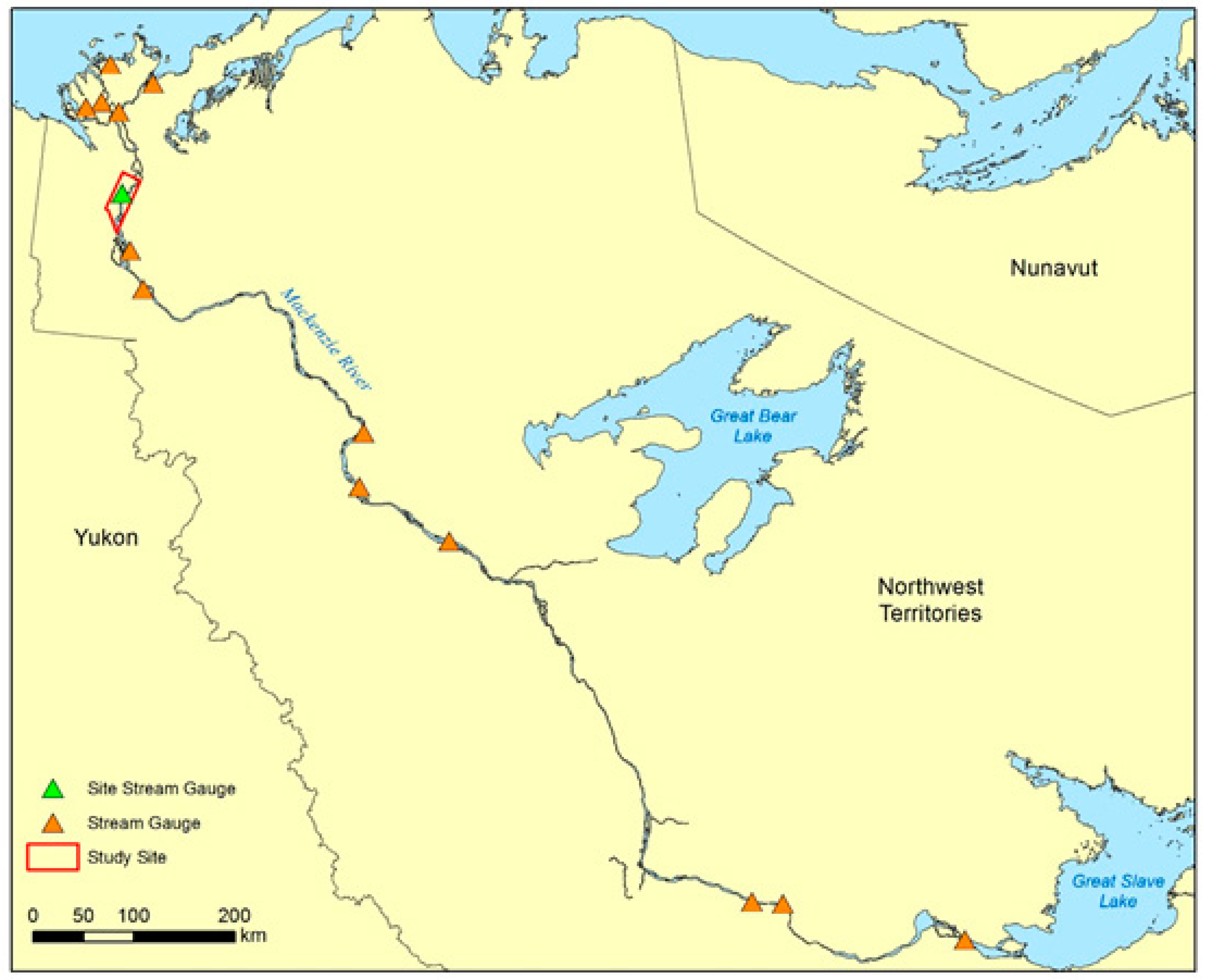
In order to cover the Mackenzie River from Great Slave Lake to the Beaufort Sea, 37 charts at the scale of 1:50,000 are required (Figure 1). This paper will focus on the section covered by chart 6428 (red outline in Figure 1) (68°28′N, 134°42′W), as this represents one area of the river where important changes have been mapped. While chart 6428 was last revised in 2011, the charted features mostly reflect the state of the river in the 1970s when the original chart was produced.

2.2. Water Level

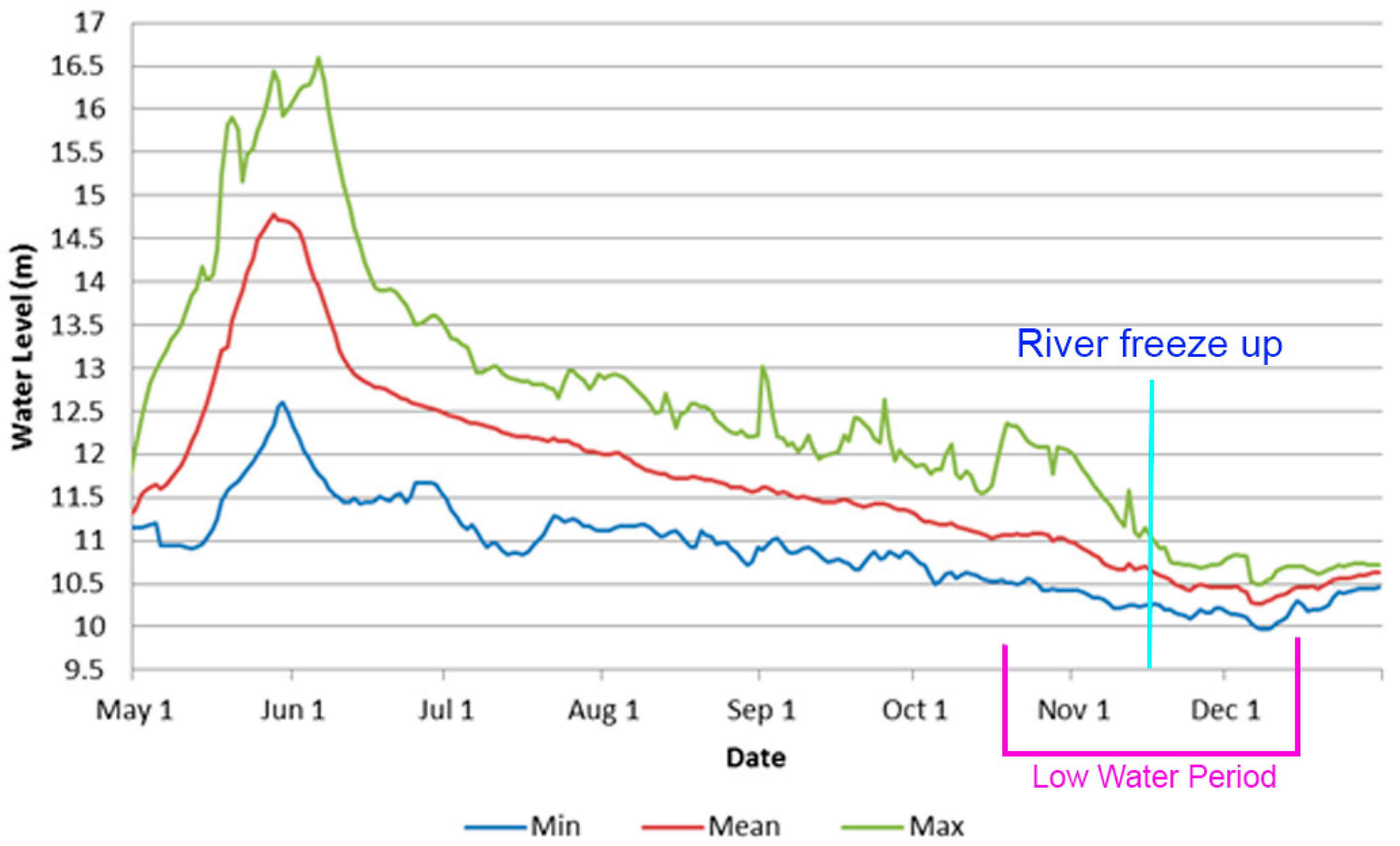
One key element for this project is the 14 water level gauges located throughout the Mackenzie River system. These gauges allowed daily mean, maximum and minimum water levels from 1982 to 2016 to be evaluated within the study area (Figure 2) [21]. Within the area of interest, the water is at its lowest level of the year within the period from late October to early December (Figure 3). For this study, to ensure that changes within the area of interest were accurately measured, images were acquired within or close to this time frame while ice-free conditions were present. Therefore, even if the lowest water level occurs in December, the best period to acquire imagery before river freeze-up is late-October to mid-November Radar imagery which is free of ice allows for the simplest separation of water and land due to the absence of strong backscattering from ice features. The water level gauges are also important to reduce soundings to chart vertical datum. In tidal conditions, CHS’s survey datasets are generally referenced to the lowest low water at large tide (LLWLT). In non-tidal waters like the Mackenzie River, chart datum is set so that the water level will be above datum approximately 95% of the time [22].

2.3. Satellite Imagery

2.3.1. RADARSAT-2

For this project there are four major advantages of using RADARSAT-2 data, making it the most critical dataset for the study:
1. Cloud-free images: Due to the large percentage of cloud cover in some areas of the Arctic, SAR imagery represents the only reliable source of data at a specific date and time.
2. Orbit accuracy: RADARSAT-2 offers a 5 m orbit accuracy with a 90% level of confidence [24].
3. Polarization: The fully polarimetric capability of RADARSAT-2 [25] will assist in coastline detection and image classification.
4. Resolution and swath size: Fine mode with a resolution of less than 10 m and a swath of 50 km, and the dual polarization option make this mode very interesting for mapping at a scale of 1:50,000. Higher resolution images such as ultra-fine and spotlight modes could also be used, but the lack of a dual polarization option could be a limiting factor for images acquired during windy conditions with these modes [25].
SAR data have become an important source of information for monitoring changes on land and water surfaces. The RADARSAT-2 sensor has been used operationally for monitoring and mapping changes in water bodies and wetlands [26,27,28]. The degree of backscatter change, resulting from surface roughness, depends on the intensity of wind and the incidence angle. In calm wind conditions, the water surface shows steady patterns represented by low and consistent backscatter, which is related to the surface water’s regular nature. The effect of incidence angle has to be accounted for, particularly when using multi-temporal images acquired with different beam modes. Usually, a rough water surface will appear brighter when the incidence angle is small [29,30]. The backscatter polarization also affects the separability between land and water. Earlier studies have shown that the HH polarization has lower backscatter over rough surface water, compared to the more sensitive VV polarization [27,31]. The use of cross polarization HV and VH is hindered by a low backscatter coefficient over the targeted water surface as it is close to the sensor’s noise floor.
In order to evaluate the best polarization to use in different wind conditions, two quad-polarization RADARSAT-2 images, representing the Fine Quad (FQ) 15 and FQ25 beam modes, were acquired on 7 October 2014 and 7 September 2016 respectively (Table 1). FQ15 and FQ25 are 25-km swath size images with a 9 × 9 m resolution, collected at 35° and 44° incidence angles respectively. The FQ15 was acquired in windy conditions with wind blowing from east to west with a speed varying from 12 to 16 m/s. The FQ25 was acquired in calm to moderate wind conditions with a wind speed varying from 5 to 7 m/s and wind direction of south-east to north-west [32]. To chart the shoreline, a spotlight mode image was also acquired on 19 October, 2015 with the HH polarization. To conduct a segmentation and classification analysis, a fine mode image was acquired on 9 October, 2017 with HH and HV polarizations.

2.3.2. Optical Data

While multiple sources of optical imagery are available, Landsat and Sentinel-2 images were selected for this study due to several advantages these systems offer for updating CHS charts:
1. Spectral resolution: Landsat-8 [33] and Sentinel-2 [34] contain spectral bands which will assist with image classification and interpretation for land cover.
2. Historical data: The historical archive of Landsat data [33] will help evaluate land cover changes and the rate of change.
3. Large swath: The 180 and 290 km swath widths for Landsat-8 [33] and Sentinel-2 [34] respectively reduce required image processing time and the number of images that need to be acquired.
4. Free data: Both Landsat-8 and Sentinel-2 represent freely available imagery sources, allowing project costs to be reduced.
Since historical data were required, Landsat imagery was primarily used for this study. Sentinel-2 imagery was acquired to extract the most recent shoreline. Table 2 summarizes the images used to detect the rate of change.

3. Methodology

3.1. SAR Polarization Selection

Environmental conditions such as water level, wind speed and wind direction during image acquisition strongly affect the contrast between water and land in HH polarized RADARSAT-2 images, making it difficult to separate these features within HH polarized images. In order to accurately evaluate the shoreline, an analysis was conducted to select the best polarization for the study. The contrast between land and water using the backscatter coefficient and its standard deviation at different polarization was evaluated.
Under a CSA DUAP project, CHS is evaluating RADARSAT Constellation Mission (RCM) data as a replacement for RADARSAT-2 data for its existing SAR applications. Since RCM images are still not available, simulated RCM products are derived using the RCM simulator developed at the Canada Centre for Mapping and Earth Observation (CCMEO). RADARSAT-2 imagery is used as input in this toolbox to generate simulated data using RCM specifications including: spatial resolution, polarization, and the Noise Equivalent Sigma Zero (NESZ). In CHS simulations, FQ15 and FQ25 images were re-processed using medium resolution of 16 m and the expected nominal NESZ for this beam mode (-25 dB). The generated RH (right circular transmit, horizontal receive) and RR (right circular transmit, right circular receive) polarization intensities are compared to RADARSAT-2 classical HH and HV polarizations. It is worth noting that as the RCM constellation will be replacing RADARSAT-2 in the near future, it is very important for CHS to ensure data and project continuity and, therefore, to test the capacity of RCM simulated backscatter in different polarizations. Ideally, RCM will be able to provide information similar or close to RADARSAT-2 data.

3.2. SAR Data Preprocessing

To reduce the effect of speckle on the calibrated RADARSAT-2 images, the fine quad and spotlight mode images were filtered using a 5 × 5 and 7 × 7 Gamma filter, respectively. Prior to the analysis of remotely sensed data, it is critical that all images are geometrically corrected with the highest accuracy possible. All RADARSAT-2 images were orthorectified using Toutin’s rigorous physical model [35], while incorporating Natural Resources Canada’s 1:50,000 Digital Elevation Models (DEM) [36].
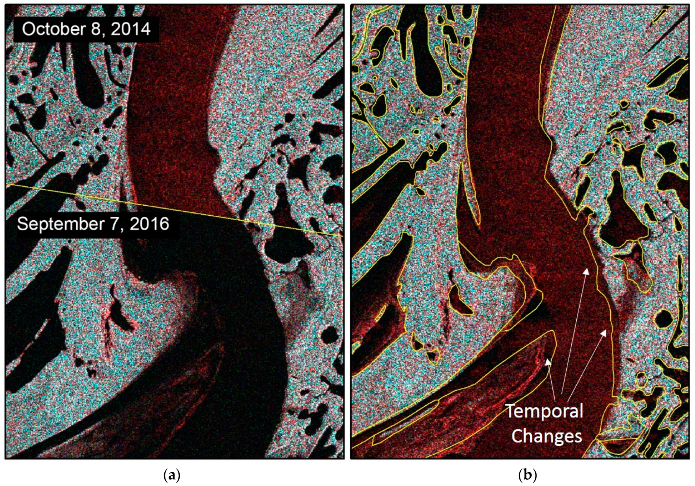
As shown in Figure 4a, the FQ orthoimages acquired from different orbits aligned at the pixel level with a relative accuracy of 5 m. Since there are no data available with higher accuracy, the absolute accuracy could not be evaluated. However, the orthoimages were compared with Canada 1:50,000 topographic data (CanVec data) [37] (Figure 4b) from 18 August 2001 which contain a horizontal accuracy of 20–30 m. CanVec is a multi-source product provided by the National Topographic Data Base (NTDB). Additionally, in some locations the CanVec data were also updated using satellite imagery by the CCMEO. The CanVec products used for this study include NTDB areas 107B06 and 107B03. Aside from areas which experienced temporal change, no large errors were noticed on the orthoimages relative to the CanVec data. Since the CanVec data are not up to date, there are temporal differences between the 2014 image and the 2001 CanVec data. These temporal differences are noted in Figure 4b, but the inland lakes that have less erosion match with both datasets, demonstrating the good relative accuracy of the orthoimages.

3.3. Optical Data Preprocessing

The level of processing used for Landsat data was the Precision and Terrain Correction, L1TP, which for the Canadian Arctic results in between one and two pixels of accuracy (30–60 m) [38]. Landsat data were converted to Top of Atmosphere (ToA) reflectance using the scaling factors stored in the image metadata and dividing by the cosine of the solar zenith angles.
The level of processing used for Sentinel-2 data was the Level-1C, which offers an accuracy between 12 m for 95% of tiles [39]. Since the aim of this study is the characterization of coastal change, the quantitative retrieval of surface spectral information, such as biophysical parameters, was not necessary. As such, further processing to Level-2A, bottom of atmosphere reflectance, was not required.

3.4. Image Segmentation and Classification

In order to make the shoreline extraction as automatic as possible, the extraction was accomplished through an object-based image segmentation process using eCognition software. Both radar and optical images were used for image segmentation and classification, including a RADARSAT-2 image acquired on 9 October 2015 and a Landsat 8 image acquired on 28 July 2017. The low water RADARSAT-2 imagery displays the maximum extent of drying areas for the images examined in this study, while the mid-year optical imagery allows visible islands to be extracted for representation on the chart based on mid-year water levels. A multiresolution segmentation algorithm was applied to define image objects by consecutively merging pixels based on a pairwise region merging technique. This is a bottom-up segmentation process that was run in eCognition using several parameters including: scale (determines the size of the objects created), shape (determines to what degree shape influences the segmentation compared to the colour and compactness), and colour and compactness (determine the relative weighting against smoothness) [40]. When executing the process, a scale of 100 was used while and shape and compactness ratios were both applied using a value of 0.5. Each band in the Landsat image was given an image layer weight of 1 and the HH and HV polarizations in the RADARSAT-2 image were given a weight of 5 in order to better define the drying areas.
A supervised classification was then run to classify each segment as land, drying area, lake or river. Approximately 15 segments were selected from each class as training sites with the mean for each band assigned to all segments. The classification algorithm in eCognition implements the nearest neighbour approach using the assigned training sites, classifying image objects in the domain based on their nearest sample neighbour [40]. The classification process was executed, and minor edits were made to reassign misclassified segments.

3.5. Rate of Change

The rate of change was calculated by compiling six optical Landsat and Sentinel-2 images from 1972 to 2018 (see first six entries in Table 2). ArcGIS 10.2 was used to generate the normalized difference water index (NDWI) raster for each image using Equation (1) [41]:
NDWI   =   Green     NIR Green   +   NIR
For both Landsat and Sentinel-2 imagery, NIR (Near Infrared) represents bands at ~840 nm while Green represents bands at ~560nm [33]. The water threshold for each image was chosen separately based on a visual evaluation. The water values for each image were then converted into a polygon and were overlaid on the current chart. A transect was drawn through the areas containing the largest visual changes in shoreline. The transects were measured from the 1972 shoreline to the 2018 shoreline. An average of the transects was taken and divided by the amount of time that passed, 46 years, to determine the average rate of change per year.

4. Results

4.1. Selection of Polarization

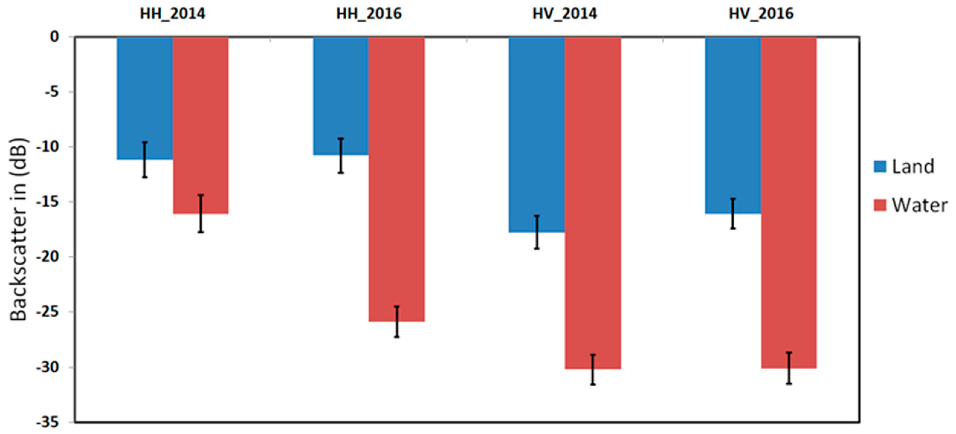
Figure 5 shows the contrast of the backscatter (in dB) between land and water for the HH and HV polarizations. Standard deviation results are represented in bars as a measure of errors of the mean values. For the 2014 image (FQ15), histograms of water/land are slightly separated in HH with thresholds of -16/-11 (dB) (relative contrast of ~4 dB) respectively, compared to the HV polarization where the thresholds reach -30/-18 (dB) and relative contrast of ~12 dB. This is expected as the image was acquired in windy conditions, increasing the water surface roughness, and therefore its backscatter coefficient. As the 2016 (FQ25) image was acquired in calm conditions, one can expect well separated histograms of the water and land in both polarizations, with thresholds of -26/-11(dB) for the HH and -30/-16 (dB) for the HV polarizations, respectively (the relative contrast is ~14 dB for both HH and HV).
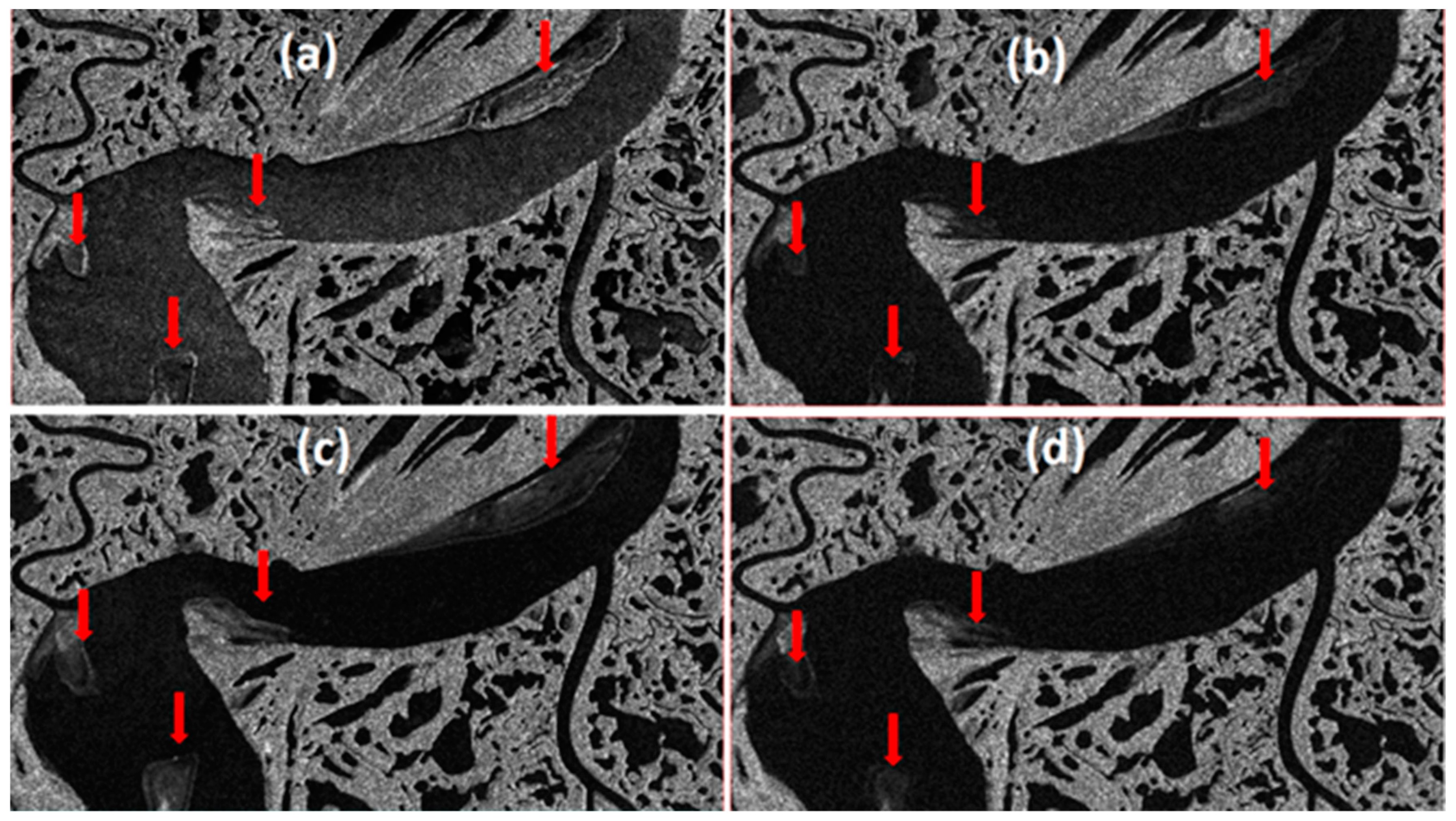
Figure 6 shows sections of the FQ15 and FQ25 HH and HV images. As shown in Figure 6a,c, surface water in HH is brighter and the contrast between land and water is not as clear as in the HV polarization images shown in Figure 6b,d. Furthermore, the mudflats show a low backscatter return in both HH and HV in calm conditions as shown in areas indicated with red arrows compared in Figure 6c,d. However, in windy conditions, the HH polarization is more adequate for discriminating these features.
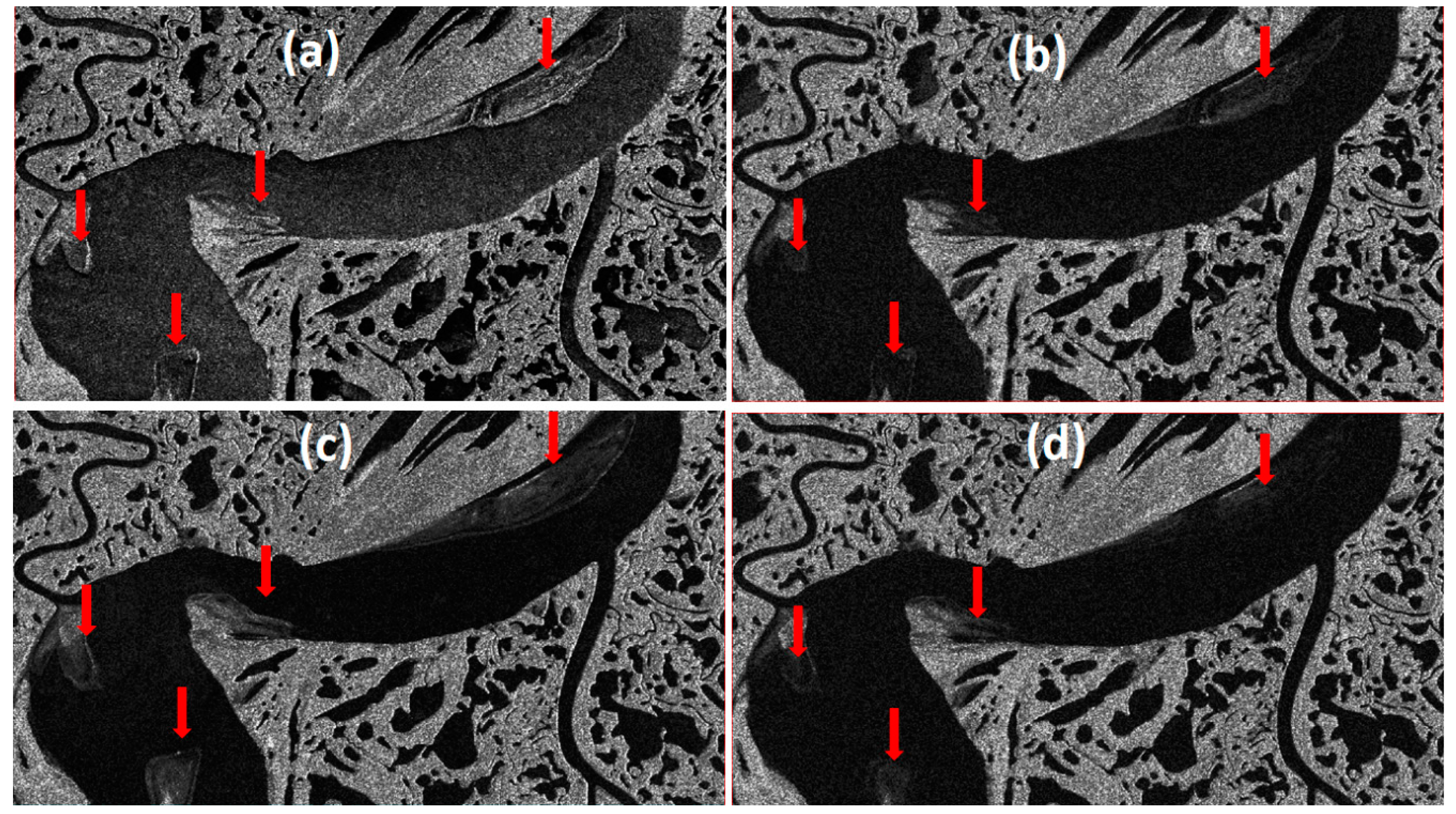
When evaluating simulated RCM data, the results demonstrate that, for the considered nominal NESZ and spatial resolution, the CP variables RH/RR produce similar separability between land and water as HH/HV (Figure 7). The relative contrast (land-water) is significant in the compact RR compared to RH in windy conditions and is almost similar in calm wind conditions (Figure 8). Similar to HH and HV, mudflat features appear darker in RH and RR polarization in calm conditions as indicated by red arrows in Figure 8.

4.2. Shoreline Extraction

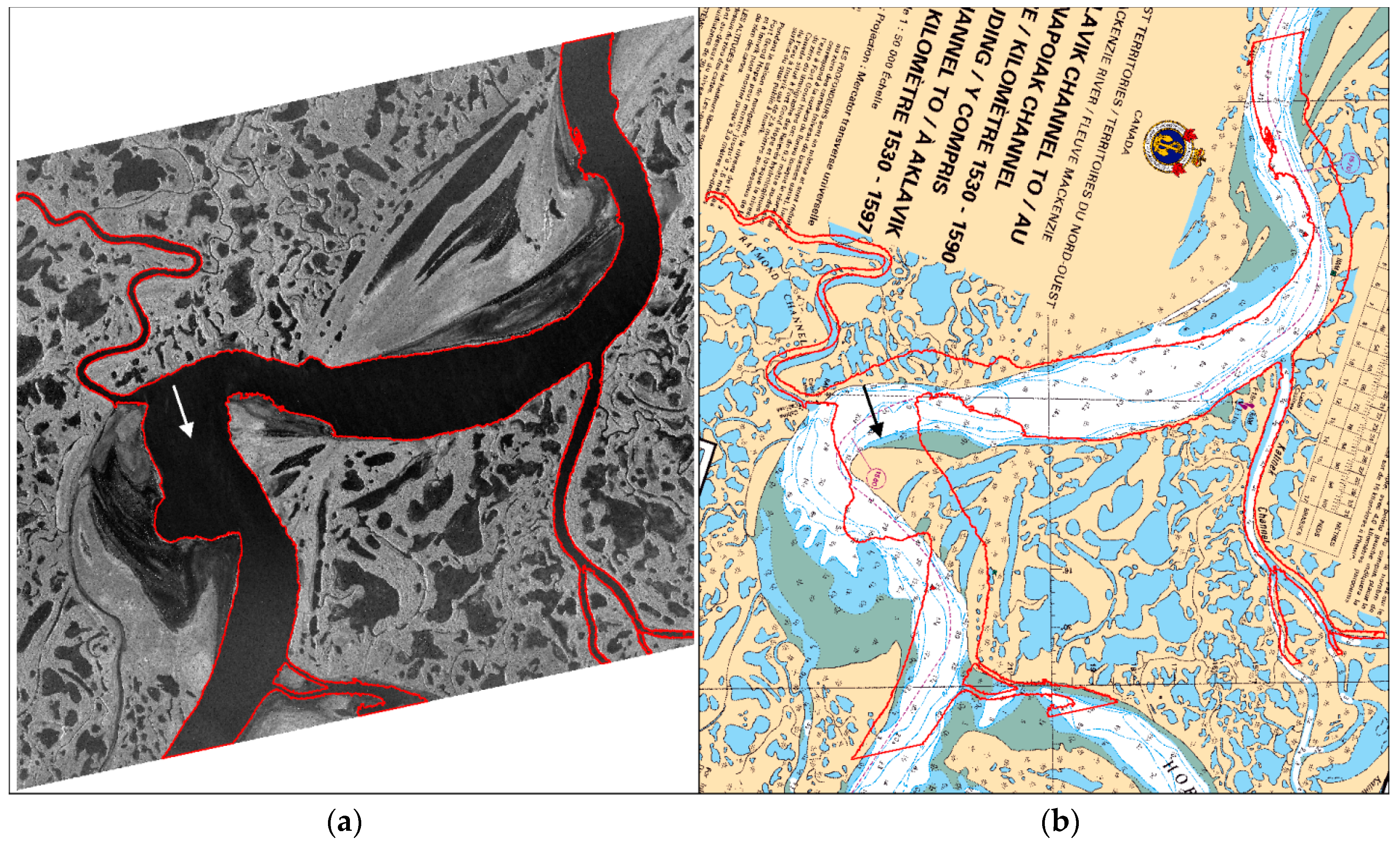
Figure 9a presents the main Mackenzie River channel as well as tributary areas derived from the satellite imagery, overlaid on the Spotlight RADARSAT-2 image for reference. The dark areas adjacent to the main channel, which flood periodically, represent drying areas. To identify changes in the river’s position since the last update of chart 6428 in 2011, a vector of the river was overlaid on a georeferenced version of the chart (Figure 9b). By comparing the current position of the river to the position illustrated on the chart, areas of change could easily be identified, providing a reference of where changes to the chart should be made. Changes in the path of the river relative to chart 6428 are visible in Figure 9b. This figure illustrates that the position of almost all portions of the river’s channel and tributaries have changed since chart 6428 was produced. This is particularly evident in the meander of the river situated just south of Raymond Channel (see white and black arrows within Figure 9a,b, respectively). At this location the full width of the river currently passes through an area of land indicated on the chart. At other locations, the recommended track shown on the chart passes through areas which are currently land. For a considerable amount of the examined area, the current chart cannot accurately be used for navigational purposes, requiring mariners to rely entirely on their judgement and aids to navigation for safely navigating these sections of the Mackenzie River.
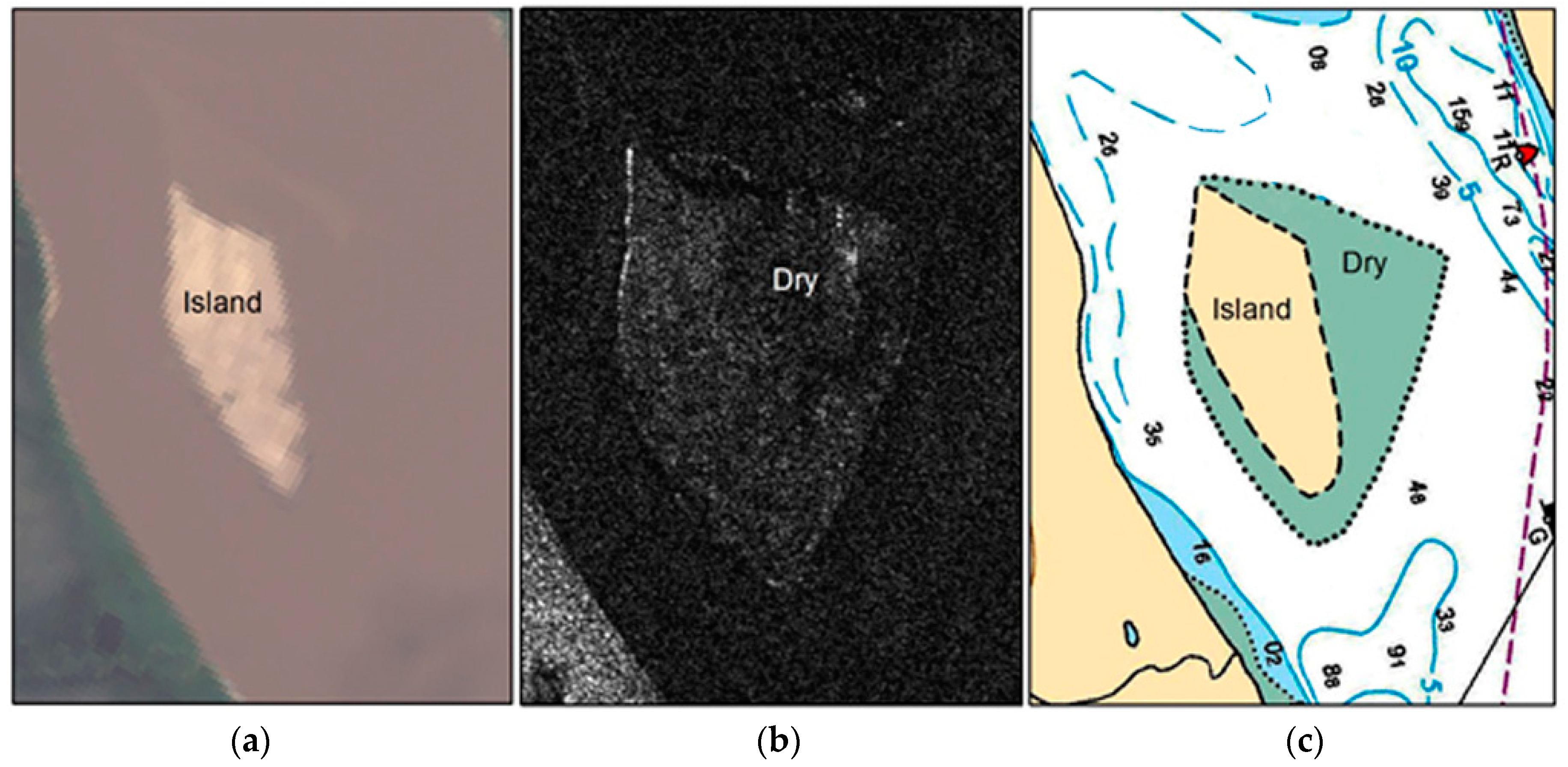
Figure 10 displays an example of segmentation and classification results from a combination of Landsat data retrieved in July 2017, and RADARSAT-2 data acquired at low water level in October 2017. The Landsat imagery represents what would be visible to a navigator during navigation season (Figure 10a, upper image) therefore these areas are mapped as land features. The low water level areas from the RADARSAT-2 imagery (Figure 10a, lower image) characterizes the extreme low water conditions of the river; therefore, this dataset is used to map what is considered a drying area. The optical and radar data can be combined to illustrate both land and drying areas on a chart (Figure 10c). For areas that have tidal variations, or intertidal zones, CHS has developed an approach where RADARSAT-2 acquisitions are synchronized with low water levels from CHS’s tidal predictions [13].

4.3. Rate of Change

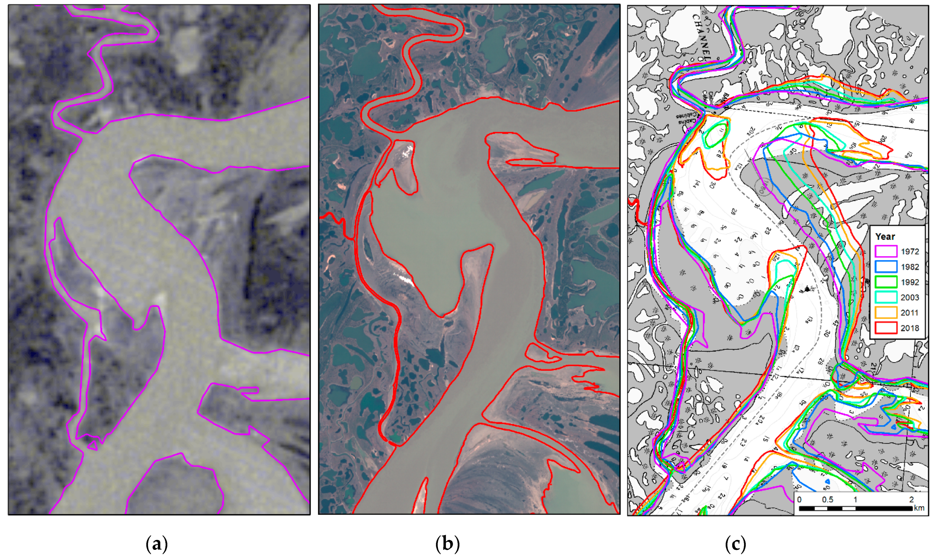
As shown in the new extracted shoreline of chart 6428 (Figure 9), the chart needs to be updated with new shorelines. Since the river is very dynamic in this location, a second aspect of the project is to evaluate the rate of change on the river to better understand the frequency at which the chart would need to be updated. As illustrated in Figure 11, by using data from the Landsat archive from 1972, 1982, 1992, 2003, 2011 and a Sentinel-2 image from 2018, a rate of change of approximately 220 m per decade was determined in the most dynamic areas within chart 6428. The rate of change was calculated by measuring the maximum distance from the vectors of the shoreline extracted from the 1972 and 2018 images. For this 46-year period, the maximum distance from the two vectors is around 1 km, which represents close to 22 metres of change per year. To better predict future changes in the river, data for every decade (1972 to 2018) were also estimated. This approach is needed to ensure that the shoreline changes were not introduced by one major event, such as a landslide. Based on the extracted shorelines, we can see in Figure 11 that although some decades, 1982 to 1992 for example, exhibit more changes, there is a gradual change in the river shoreline between each decade. Therefore, we can suspect that this general trend will continue to occur in the future and thus special attention will be required in those areas of the river to ensure that the charts are up to date. The detail at which a cartographer can update a map/chart is half a millimetre at chart scale. The scale of chart 6428 is 1:50,000; as such, 0.5 mm on the chart represents 25 m on the ground. With a rate of change of approximately 22 m/year, this chart would need to be revaluated at least every two years.

5. Discussion

A comparison of RADARSAT-2 FQ15 HH and HV and FQ25 HH and HV images confirms the higher sensitivity of the HV polarization to the presence of surface water. Based on these results, HV has a higher capability in differentiating between land and water. The backscatter coefficient at cross-polarization is contaminated by the noise floor. This results in an inability to detect mudflat areas relative to the HH polarized imagery, as shown in the four zones identified by arrows in Figure 6. One can assume that the smooth surface combined with soil water saturation in these mudflats made HV decrease more significantly in comparison to HH. Consequently, the effect of dielectric constants on backscattered signals can be neglected in this case [20,42,43,44]. Using both polarizations for the classification increases the contrast between land and water and therefore improves retrieval accuracy. Additionally, a simulated RCM comparison indicates the compact parameters RH and RR on RCM should be able to be used as successfully as the HH/HV polarizations for separating land and water, and more specifically for the detection of mudflat areas.
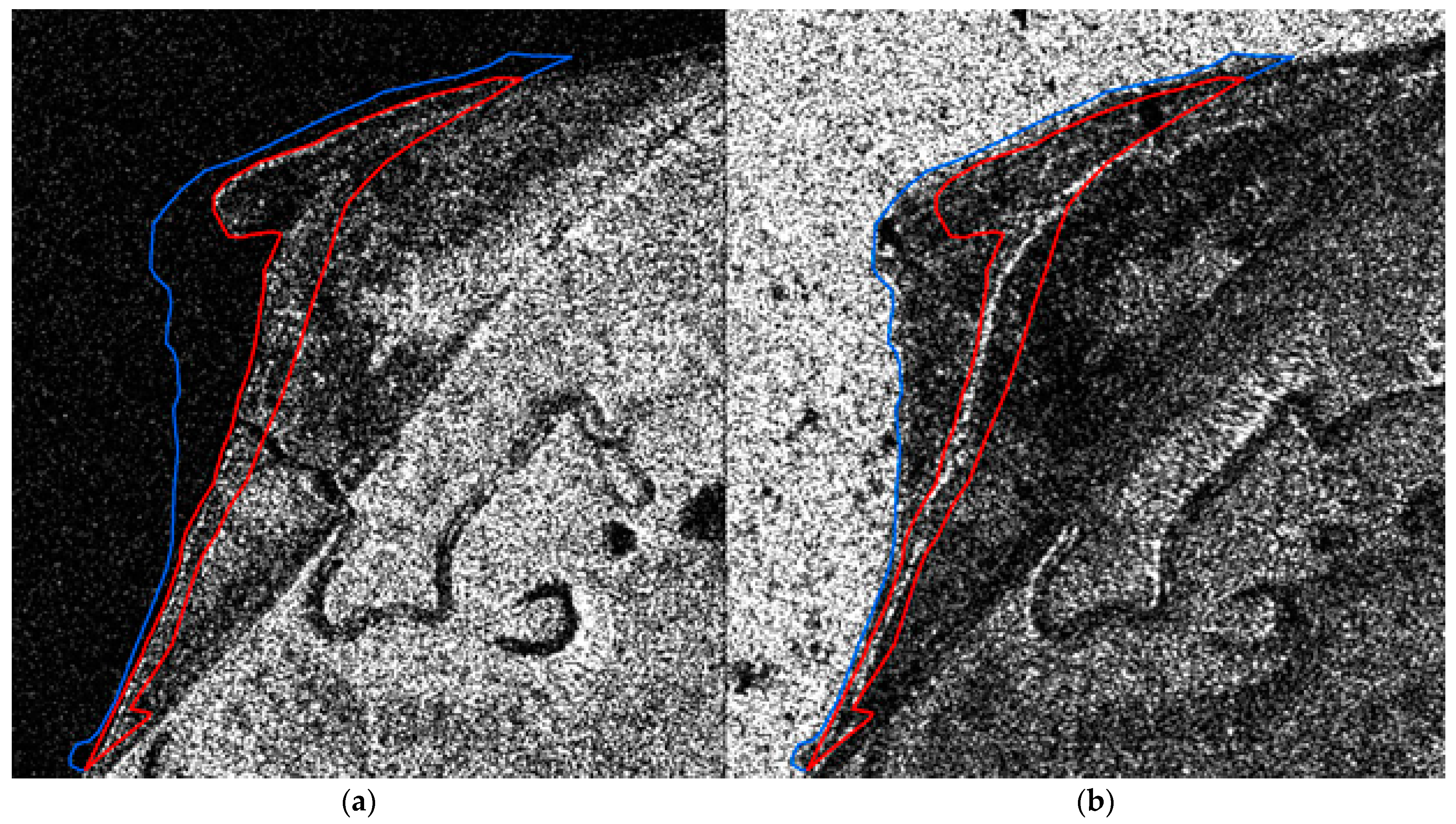
It is preferable to acquire RADARSAT-2 data at the lowest water level possible with no ice cover; however, early winter periods generally contain the lowest water levels (Figure 3) [4], allowing submerged features to become more visible than at other times of the year. Even if the area contains ice, these images could also be valuable for extracting the low water line at the lowest water level possible (Figure 12), increasing navigation safety. For automatic extraction and interpretation purposes it is preferable to have an image with no ice, but as demonstrated in Figure 12, the image with ice can be used to manually extend the shoreline to the lowest water level.
Results of the change detection analysis completed for chart 6428 illustrates the degree to which remotely sensed data can improve Canadian nautical charts in remote areas. The use of RADARSAT-2 imagery is sufficient to separate land and water with a reasonable accuracy. Consequently, this imagery can be used to better define the main Mackenzie River channel, as well as its larger tributaries. This was achieved through a simple image segmentation process, allowing the shoreline of approximately 18 km of the river to be mapped with minimal effort and at little cost. In its current form, the change detection approach could be applied for the entire length of the Mackenzie River, allowing for a current representation of the shoreline to be incorporated into the river’s charts. At a minimum, this would provide mariners with a more representative indication of the position of shoreline and island features within the waterway, allowing them to make more informed decisions for safe navigation. Since 2014, CHS has been using this proposed approach to update different charts on the Mackenzie River. Figure 13 is an example of another chart (6424) that was updated with Earth observation (EO) data. In this example, the advantages of using the hybrid approach of radar (low water level) and optical (mid-water level) data to chart land and drying areas are well illustrated.
In order to simplify the chart update process in dynamic areas, all features are extracted as vectors and coded in the International Hydrographic Organisation (IHO) S-57 Electronic Navigation Chart (ENC) format [45]. This format ensures easy integration with CHS’s existing charts and future chart updates. For a considerable number of the examined areas, the current chart cannot accurately be used for navigational purposes, requiring mariners to rely entirely on their judgement for navigating these sections of the Mackenzie River. In order to fully correct the Mackenzie charts, new survey information is required in the areas of change. In a pilot project for chart 6424, the CCG agreed to collect survey data for CHS within the identified areas of change on the Mackenzie [3]. Figure 14 is an example of the prototype chart that was created with EO data and new survey information collected by CCG. Since CCG is already providing the information for the navigation track on the chart (magenta dashed line) and placing the navigation aids along the track, they could provide the collected depth measurements when charting the suggested track. Thus, two options could be used by CHS: (1) remove surveys in the dynamic areas of the river and update the charts with new shorelines, or (2) use the survey information collected from CCG or other crowdsourced information and update the shoreline. Figure 14 represents the second option, where the survey data collected by CCG was used to update the chart. One of the main advantages of the Mackenzie River system is that there is a good network of tidal gauges that can be used to reduce the soundings collected by CCG to chart datum.

6. Conclusions

Keeping over 1000 nautical charts up to date is a challenge that CHS faces, primarily in dynamic areas such as the Mackenzie River. In this paper, CHS has proposed several techniques to improve the quality of charts using a multi-sensor SRS approach. The proposed hybrid approach, that leverages the advantages of SAR and optical data, is a cost effective and accurate technique to update charts in dynamic areas. The use of RADARSAT-2 is beneficial for capturing low water conditions during periods of high cloud cover (October to December), thus ensuring that shorelines representing the lowest water level possible is mapped. RADARSAT-2 orthoimages have a horizontal accuracy of 5 m which is important to ensure high positioning accuracy for safe navigation. It is suggested to use both HH and HV polarizations for classification in order to increase the contrast between land and water, and to improve the retrieval accuracy. As RCM will be replacing the RADARSAT-2 mission, the compact polarimetry parameters RH and RR of RCM proved to behave similarly to HH/HV polarizations for separating land and water, and more specifically for the detection of mudflat areas. One weakness of SAR data is that image noise can make interpretation difficult, especially under windy acquisition conditions. Since it is difficult to acquire cloud-free optical imagery during the low water period, having an optical multispectral image acquired during the summer months helps with land/water interpretation and is also beneficial to differentiate between land and drying areas.
Object-based image segmentation applied to RADARSAT-2 and optical imagery allowed for excellent separation of land and water features for a northern section of the Mackenzie River. A comparison of the extracted river channel and tributaries with CHS chart 6428 revealed significant differences in the river’s location. In some instances, nearly the full width of the river currently passes through areas of land identified on the chart. After extracting the shoreline of six historical Landsat images of the area, the Mackenzie River shoreline was measured to be moving at a rate of approximately 20 m/year in areas of maximum change. This change indicates that the chart should be updated every 2–3 years in order to ensure safe navigation for mariners.
To further improve the quality of charts, CHS proposed applying the following steps:
1. applying segmentation and classification to acquired SAR and optical datasets to chart the full length of the Mackenzie river as well as other dynamic coastal areas in Canada;
2. using multi-temporal data to understand river dynamics at various water levels throughout the year, and
3. acquiring crowdsourced survey data from ships passing through the Mackenzie River, such as the CCG.
Through additional work to extend the application of the studied approach across the entire length of the Mackenzie River system, we expect significant improvements to the charting of dynamic river systems across Canada. There are also many other areas of Canadian waters that are dynamic. For example, the Arctic coastline is retreating by half a meter per year [46]; the changes are particularly dramatic in the Beaufort Sea along the coast of the Northwest Territories and Yukon Territory. The constant erosion of coastlines and poor source data has led CHS to look at alternative solutions for mapping and surveying Canadian waters. Other hydrographic offices, such as the National Oceanic and Atmospheric Administration (NOAA), are exploring remote sensing techniques to better chart dynamic areas. In 2016, NOAA Office of Coast Survey issued provisional charts for the Yukon River, relying solely on satellite images to create the electronic navigational charts that only display shoreline and shoals [47]. The usage of the EO techniques outlined in this study and proposed by CHS in 2014 [12] to update dynamic systems is a cost-effective technique and creates up-to-date products. Although the use of multibeam data is still the most accurate approach, this technique is not cost efficient for the Mackenzie River since it is a highly dynamic system. Thus, the advantages of having centimeter accurate survey data is lost by the rapidly changing water depths. Therefore, approaches based on the use of EO techniques and crowdsourced information that are less accurate than traditional techniques can provide a better representation of the river when performed more frequently.

Author Contributions

Conceptualization, methodology, supervision, project administration and funding acquisition, R.C.; formal analysis, investigation and validation, K.O., R.A. and M.S.; Writing—original draft preparation, R.C., K.O., R.A., and M.S.; and writing—review & editing, R.C., K.O., R.A., and M.S.

Funding

To complete this work The CHS received support through the Canadian Space Agency’s Government Related Initiatives Program (GRIP) and the Data Utilization Application Plan (DUAP).

Acknowledgments

Thank you to Loretta Abado for her help in the review and editing of the article.

Conflicts of Interest

The authors declare no conflict of interest. The funders had no role in the design of the study; in the collection, analyses, or interpretation of data; in the writing of the manuscript, or in the decision to publish the results.

References

  1. Riopel, S.; Couture, R.; Tewari, K. Mapping susceptibility to landslides in a permafrost environment: Case study in the Mackenzie Valley, Northwest Territories. In Proceedings of the GeoTech Event 2006, Ottawa, ON, Canada, 18–21 June 2006. [Google Scholar]
  2. Carson, M.A.; Jasper, J.N.; Conley, F.M. Magnitude and sources of sediment input to the Mackenzie Delta, Northwest Territories, 1974–1994. Arctic 1998, 51, 116–124. [Google Scholar] [CrossRef]
  3. Chénier, R.; Ahola, R.; Sagram, M.; Faucher, M.-A.; Shelat, Y. Consideration of Level of Confidence within Multi-Approach Satellite-Derived Bathymetry. ISPRS Int. J. Geo Inf. 2019, 8, 48. [Google Scholar] [CrossRef]
  4. Marcus, W.A.; Fonstad, M.A. Optical remote mapping of rivers at sub-meter resolutions and watershed extents. Earth Surf. Process. Landf. 2008, 33, 4–28. [Google Scholar] [CrossRef]
  5. Bizzi, S.; Demarchi, L.; Grabowski, R.C.; Weissteiner, C.J.; Van de Bund, W. The use of remote sensing to characterise hydromorphological properties of European rivers. Aquat. Sci. 2016, 78, 57–70. [Google Scholar] [CrossRef]
  6. Neal, J.; Schumann, G.; Bates, P.; Buytaert, W.; Matgen, P.; Pappenberger, F. A data assimilation approach to discharge estimation from space. Hydrol. Process. 2009, 23, 3641–3649. [Google Scholar] [CrossRef]
  7. Rinaldi, M.; Surian, N.; Comiti, F.; Busettini, M. A method for the assessment and analysis of the hydromorphological condition of Italian streams: The Morphological Quality Index (MQI). Geomorphology 2013, 180, 96–108. [Google Scholar] [CrossRef]
  8. Spada, D.; Molinari, P.; Bertoldi, W.; Vitti, A.; Zolezzi, G. Multi-Temporal Image Analysis for Fluvial Morphological Characterization with Application to Albanian Rivers. ISPRS Int. J. Geo Inf. 2018, 7, 314. [Google Scholar] [CrossRef]
  9. Van der Sanden, J.J.; Drouin, H.; Bian, Y. Repeat Pass InSAR Observations of River and Lake Ice Cover: A Preliminary Evaluation of Information Content. In Proceedings of the 17th Workshop on River Ice, Edmonton, AB, Canada, 21–24 July 2013. [Google Scholar]
  10. Ullman, T.; Schmitt, A.; Jagdhuber, T. Two Component Decomposition of Dual Polarimetric HH/VV SAR Data: Case Study for the Tundra Environment of the Mackenzie Delta Region, Canada. Remote Sens. 2016, 8, 1027. [Google Scholar] [CrossRef]
  11. Normandin, C.; Frappart, F.; Lubac, B.; Bélanger, S.; Marieu, V.; Blarel, F.; Robinet, A.; Guiastrennec-Faugas, L. Quantification of surface water volume changes in the Mackenzie Delta using satellite multi-mission data. Hydrol. Earth Syst. Sci. 2018, 22, 1543–1561. [Google Scholar] [CrossRef] [Green Version]
  12. Chénier, R.; Hemmingway, C. Updating CHS Charts with Remote Sensing Data—A RADAR and Optical Approach. In Proceedings of the Canadian Hydrographic Conference 2014 (CHC2014), St. John’s, NL, Canada, 14–17 April 2014. [Google Scholar]
  13. Chénier, R.; Faucher, M.A.; Ahola, R.; Jiao, X.; Tardif, L. Remote Sensing Approach for Updating CHS Charts. In Proceedings of the Canadian Hydrographic Conference, Halifax, NS, Canada, 16–17 May 2016. [Google Scholar]
  14. Chénier, R.; Faucher, M.A.; Ahola, R. Satellite-derived bathymetry for improving Canadian Hydrographic Service charts. ISPRS Int. J. Geo-Inf. 2018, 7, 306. [Google Scholar] [CrossRef]
  15. Canada’s Next-Generation RADARSAT Satellite Constellation Successfully Launches to Space. Available online: https://www.canada.ca/en/space-agency/news/2019/06/canadas-next-generation-radarsat-satellite-constellation-successfully-launches-to-space.html (accessed on 17 June 2019).
  16. Charbonneau, F.; Brisco, B.; Raney, K.; McNairn, H.; Liu, C.; Vachon, P.; Shang, J.; De Abreu, R.; Champagne, C.; Merzouki, A.; et al. Compact polarimetry overview and applications assessment. Can. J. Remote Sens. 2010, 36, S298–S315. [Google Scholar] [CrossRef]
  17. Daboor, M.; Geldsetzer, T. Towards sea ice classification using simulated RADARSAT constellation mission compact polarimetric SAR imagery. Remote Sens. Environ. 2014, 140, 189–195. [Google Scholar] [CrossRef]
  18. Geldsetzer, T.; Arkettt, M.; Zagon, T.; Charbonneau, F.; Yackel, J.; Scharien, R. All-season compact-polarimetry C-band SAR observations of sea ice. Can. J. Remote Sens. 2015, 41, 485–504. [Google Scholar] [CrossRef]
  19. White, L.; Millard, K.; Banks, S.; Richardson, M.; Pasher, J.; Duffe, J. Moving to the RADARSAT Constellation Mission: Comparing Synthesized Compact Polarimetry and Dual Polarimetry Data with Fully Polarimetric RADARSAT-2 Data for Image Classification of Peatlands. Remote Sens. 2017, 9, 573. [Google Scholar] [CrossRef]
  20. Banks, S.; Millard, K.; Behnamian, A.; White, L.; Ullman, T.; Charbonneau, F.; Chen, Z.; Wang, H.; Pasher, J.; Duffe, J. Contributions of Actual and Simulated Satellite SAR Data for Substrate Type Differentiation and Shoreline Mapping in the Canadian Arctic. Remote Sens. 2018, 9, 1206. [Google Scholar] [CrossRef]
  21. Daily Discharge Graph for Mackenzie River (Middle Channel) Below Raymond Channel (10MC008) [NT]. Available online: https://wateroffice.ec.gc.ca/report/statistics_e.html?stn=10MC008 (accessed on 26 October 2018).
  22. Historical Hydrometric Data Map Search. Available online: https://wateroffice.ec.gc.ca/google_map/google_map_e.html?map_type=historical&search_type=province&province=NT (accessed on 26 October 2018).
  23. Download Geographical Names Data. Available online: https://www.nrcan.gc.ca/earth-sciences/geography/ place-names/data/9245 (accessed on 20 March 2019).
  24. Toutin, T.; Omari, K. DTM generation with Radarsat-2 Data without GCP. In Proceedings of the ISPRS Hannover Workshop 2011: International Archives of the Photogrammetry, Remote Sensing and Spatial Information Science, Hannover, Germany, 14–17 June 2011. [Google Scholar]
  25. Maxar Technologies Ltd. Radarsat-2 Product Description; MDA: Richmond, BC, Canada, 2018; pp. 1–9. [Google Scholar]
  26. White, L.; Brisco, B.; Pregitzer, M.; Tedford, B.; Boychuk, L. RADARSAT-2 Beam Mode Selection for Surface Water and Flooded Vegetation Mapping. Can. J. Remote Sens. 2014, 40, 135–151. [Google Scholar]
  27. Brisco, B.; Short, N.; van der Sanden, J.; Landry, R.; Raymond, D. A semi-automated tool for surface water mapping with RADARSAT-1. Can. J. Remote Sens. 2009, 35, 336–344. [Google Scholar] [CrossRef]
  28. Bolanos, S.; Stiff, D.; Brisco, B.; Pietroniro, A. Operational Surface Water Detection and Monitoring Using Radarsat 2. Remote Sens. 2016, 8, 285. [Google Scholar] [CrossRef]
  29. Santoro, M.; Wegmuller, U.; Lamarche, C.; Bontemps, S.; Defourny, P.; Arino, O. Strengths and weaknesses of multi-year Envisat ASAR backscatter measurements to map permanent open water bodies at global scale. Remote Sens. Environ. 2015, 171, 185–201. [Google Scholar] [CrossRef]
  30. Pham-Duc, B.; Prigent, C.; Aires, F. Surface Water Monitoring within Cambodia and the Vietnamese Mekong Delta over a Year, with Sentinel-1 SAR Observations. Water 2017, 9, 366. [Google Scholar] [CrossRef]
  31. Manjusree, P.; Prasanna Kumar, L.; Bhatt, C.; Rao, G.; Bhanumurthy, V. Optimization of threshold ranges for rapid flood inundation mapping by evaluating backscatter profiles of high incidence angle SAR images. Int. J. Disaster Risk Sci. 2012, 3, 112–122. [Google Scholar] [CrossRef]
  32. Historical Data. Available online: http://climate.weather.gc.ca/historical_data/search_historic_data_e.html (accessed on 20 March 2019).
  33. U.S. Geological Survey. Available online: https://landsat.usgs.gov (accessed on 20 March 2019).
  34. Sentinel Online. Available online: https://sentinel.esa.int/web/sentinel/missions/sentinel-2/instrument-payload/ resolution-and-swath (accessed on 20 March 2019).
  35. Toutin, T.; Chénier, R. 3-D Radargrammetric Modeling of RADARSAT-2 Ultrafine Mode: Preliminary Results of the Geometric Calibration. IEEE Geosci. Remote Sens. Lett. 2009, 6, 611–615. [Google Scholar] [CrossRef]
  36. Canadian Digital Elevation Model. Available online: https://open.canada.ca/data/en/dataset/7f245e4d-76c2-4caa-951a-45d1d2051333 (accessed on 20 March 2019).
  37. Lakes, Rivers and Glaciers in Canada—CanVec Series—Hydrographic Features. Available online: https://open.canada.ca/data/en/dataset/9d96e8c9-22fe-4ad2-b5e8-94a6991b744b (accessed on 20 March 2019).
  38. Geometric Accuracy. Available online: https://landsat.usgs.gov/geometry (accessed on 20 March 2019).
  39. Clerc, S.; MPC Team. S2 MPC L1C Data Quality Report; ESA Copernicus, 2019; Available online: https://sentinel.esa.int/documents/247904/685211/Sentinel-2_L1C_Data_Quality_Report (accessed on 20 March 2019).
  40. eCognition Developer Trimble. eCognition® Developer User Guide; eCognition Developer Trimble: München, Germany, 2014. [Google Scholar]
  41. McFeeters, S.K. The use of the Normalized Difference Water Index (NDWI) in the delineation of open water features. Int. J. Remote Sens. 1996, 17, 1425–1432. [Google Scholar] [CrossRef]
  42. Gade, M.; Alper, W.; Melsheimer, C.; Tanck, G. Classification of sediments on exposed tidal flats in the German Bight using multi-frequency radar data. Remote Sens. Environ. 2008, 112, 1603–1613. [Google Scholar] [CrossRef]
  43. Park, S.-E.; Moon, W.E.; Kim, D.; Kim, J.-E. Estimation of surface roughness parameter in intertidal mudflat using airborne polarimetric SAR data. IEEE Trans. Geosci. Remote Sens. 2009, 47, 1022–1031. [Google Scholar] [CrossRef]
  44. Van der Wal, D.; Herman, P.M.J.; Wielemaker-van Den Dool, A. Characterisation of surface roughness and sediment texture of intertidal flats using ERS SAR imagery. Remote Sens. Environ. 2005, 98, 96–109. [Google Scholar] [CrossRef]
  45. International Hydrographic Organization. IHO Transfer Standard for Digital Hydrographic Data; International Hydrographic Organization: Monaco, 2000. [Google Scholar]
  46. Lantuit, H.; Overduin, P.P.; Couture, N.; Wetterich, S.; Aré, F.; Atkinson, D.; Brown, J.; Cherkashov, G.; Drozdov, D.; Forbes, D.L.; et al. The Arctic Coastal Dynamics Database: A New Classification Scheme and Statistics on Arctic Permafrost Coastlines. Estuaries Coasts 2012, 35, 383–400. [Google Scholar] [CrossRef]
  47. Howard, M. Yukon River Charts Produced with Satellite Images. Marine Technology News, 12 January 2016. Available online: https://www.marinetechnologynews.com/news/yukon-river-charts-produced-526382 (accessed on 13 March 2019).
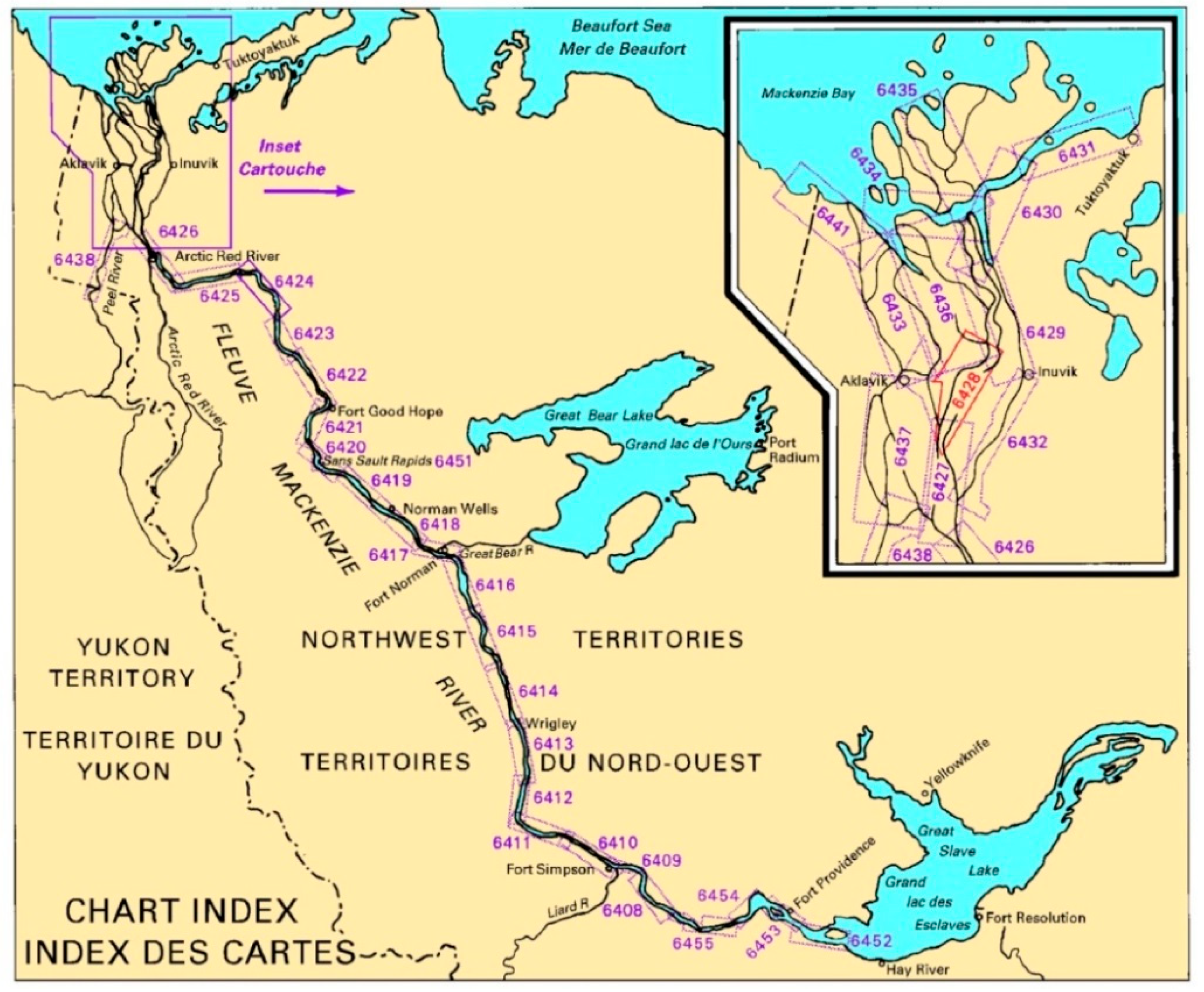
Figure 1. Mackenzie River chart index. Chart 6428 is highlighted in the inset (red polygon).
Remotesensing 11 01523 g001
Figure 2. Water level stream gauges located on the Mackenzie River [22] are displayed in orange, while the gauge used for the study (10MC008) is shown in green. Chart 6428 is outlined by the red polygon [23]. Basemap © GEBCO and Natural Resources Canada
Remotesensing 11 01523 g002
Figure 3. Mean, maximum and minimum daily water levels for the Mackenzie River at guage 10MC008. The values represent monthly averages calculated using observations from 1982–2016 [21]. The low water period is between late October to early December with a river freeze up in mid-November; therefore, the best period to obtain ice free imagery would be late October to mid-November.
Remotesensing 11 01523 g003
Figure 4. Comparison between (a) the relative accuracy of the FQ RADARSAT-2 orthoimages from 8 October 2014 and 7 September 2016, and (b) the absolute accuracy of the orthorectified FQ RADARSAT-2 from 8 October 2014 and Canada 1:50,000 topographic data (CanVec data) from 14 March 2016. RADARSAT-2 Data and Products © MacDonald, Dettwiler and Associates Ltd. (2014/2016) – All Rights Reserved. RADARSAT is an official mark of the Canadian Space Agency.
Remotesensing 11 01523 g004
Figure 5. Land-water contrast in HH and HV polarizations.
Remotesensing 11 01523 g005
Figure 6. RADARSAT-2 FQ15 HH (a), HV (b) and FQ25 HH (c), HV (d) images acquired over the study area on 8 October 2014 and 7 September 2016 respectively. The red arrows point to mud-flat areas that can be clearly distinguished in HH but are barely visible in HV. RADARSAT-2 Data and Products © MacDonald, Dettwiler and Associates Ltd. (2014/2016) – All Rights Reserved. RADARSAT is an official mark of the Canadian Space Agency.
Remotesensing 11 01523 g006
Figure 7. Land-water contrast in RH and RR polarizations.
Remotesensing 11 01523 g007
Figure 8. Simulated RCM RH (a), RR (b) (8 October 2014) and RH (c), RR (d) (7 September 2016) images acquired over the study area. The red arrows point to mud-flat areas in RH and RR in calm and windy conditions.
Remotesensing 11 01523 g008
Figure 9. Segmentation result showing extracted main Mackenzie River channel and tributaries over the RADARSAT-2 Spotlight image (a) and over chart 6428 (b). Note the arrow on both maps: on map (a), the arrow is situated near the current centre of the main Mackenzie River channel. On map (b), chart 6428 indicates an area of land at the same location. The charted land area spans nearly the entire width of the current river’s location at this point. These graphics highlight significant changes in the position of the river since the creation of chart 6428. RADARSAT-2 Data and Products © MacDonald, Dettwiler and Associates Ltd. (2014/2016) – All Rights Reserved. RADARSAT is an official mark of the Canadian Space Agency.
Remotesensing 11 01523 g009
Figure 10. Demonstration of how optical and radar imagery are used to illustrate dry areas and islands in charts, with (a) the optical Landsat-8 image from 28 July 2017 displaying an island and the RADARSAT-2 image from 9 October 2015 displaying a dry area; (b) segmentation produced using the optical Landsat-8 image overlaid on the RADARSAT-2 image; and (c) a classification of the combined images displaying the Mackenzie River, lakes, land and drying areas. Imagery © 2015, U.S. Geological Survey and RADARSAT-2 Data and Products © MacDonald, Dettwiler and Associates Ltd. (2014/2016) – All Rights Reserved. RADARSAT is an official mark of the Canadian Space Agency.
Remotesensing 11 01523 g010
Figure 11. Segmentation result showing extracted main Mackenzie River channel and tributaries over a Landsat image from 1972 (a), a Sentinel-2 image from 2018 (b) and over chart 6428 (c). Imagery © 1972, U.S. Geological Survey and © 2018, Copenicus.
Remotesensing 11 01523 g011
Figure 12. Comparison of uncharted covering/uncovering areas between RADARSAT-2 acquisitions. The image shown in (a) was acquired on 12 October 2015, prior to the development of ice. The uncharted covering/uncovering area visible at this time is outlined in red. Map (b) shows an image acquired on 10 November 2015. Bright white areas indicate the presence of ice. Note the much larger covering/uncovering area (blue outline) visible on map (b), a result of lower water levels during the early winter period. RADARSAT-2 Data and Products © MacDonald, Dettwiler and Associates Ltd. (2014/2016) – All Rights Reserved. RADARSAT is an official mark of the Canadian Space Agency.
Remotesensing 11 01523 g012
Figure 13. (a) Landsat-8 imagery from 5 August, 2015 and (b) RADARSAT-2 imagery from 6 October, 2015 are combined in (c) to display an example of how a combination of optical and radar imagery can identify islands and drying areas on charts.
Remotesensing 11 01523 g013
Figure 14. Example of the current edition of Chart 6424 (left) and prototype chart updated with EO data and new survey data from CCG vessels (right) [3].
Remotesensing 11 01523 g014
Table 1. RADARSAT-2 metadata with water level [22]. All images were obtained in Single Look Complex format.
Acquisition DateAcquisition Time (UTC)Beam ModePolarizationWater Level (m)
October 8, 201415:39:39FQ15HH, HV, HV, VV12.125
September 7, 201615:39:45FQ 25HH, HV, HV, VV11.482
October 19, 201502:31:31Spotlight 15HH11.075
October 9, 201715:39:45Fine 23HH, HV11.337
Table 2. Optical data summary including red (R), green (G), blue (B), near infrared (NIR) and short-wave infrared (SWIR) band usage and acquisition dates and associated daily water level [32].
SourceBandsAcquisition DateWater Level (m)
Landsat-1G, R, NIRSeptember 4, 1972N/A
Landsat-3G, R, NIRJuly 14, 198211.635
Landsat-5B, G, R, NIR, SWIRJuly 25, 199212.297
Landsat-5B, G, R, NIR, SWIRAugust 9, 200312.224
Landsat-5B, G, R, NIR, SWIRAugust 31, 201111.741
Sentinel-2B, G, R, NIRJune 13, 201812.896
Landsat-8B, G, R, NIR, SWIRJuly 28, 2017N/A