Direct Georeferencing of a Pushbroom, Lightweight Hyperspectral System for Mini-UAV Applications

 , , ,
, , ,
Abstract
:
1. Introduction
- -
- -
- -
- -
- -
2. Materials and Methods
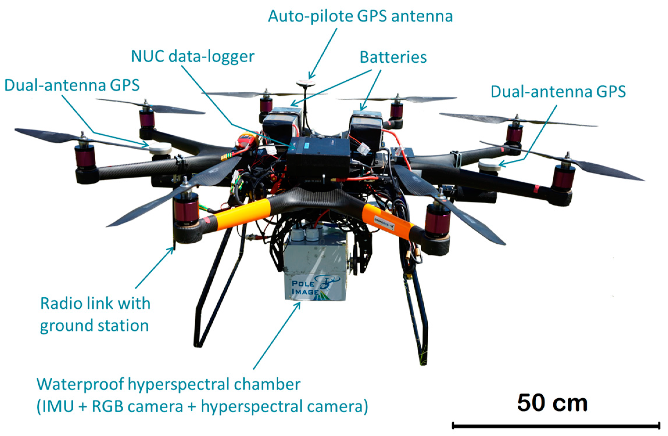
2.1. UAV Platform
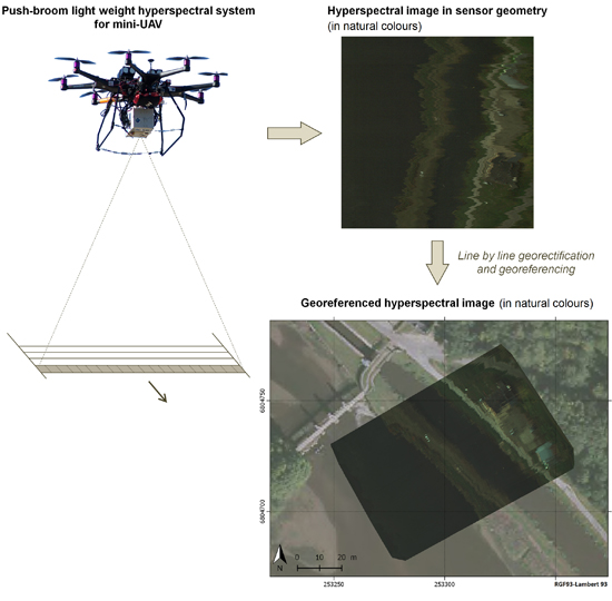
2.2. Imaging Module
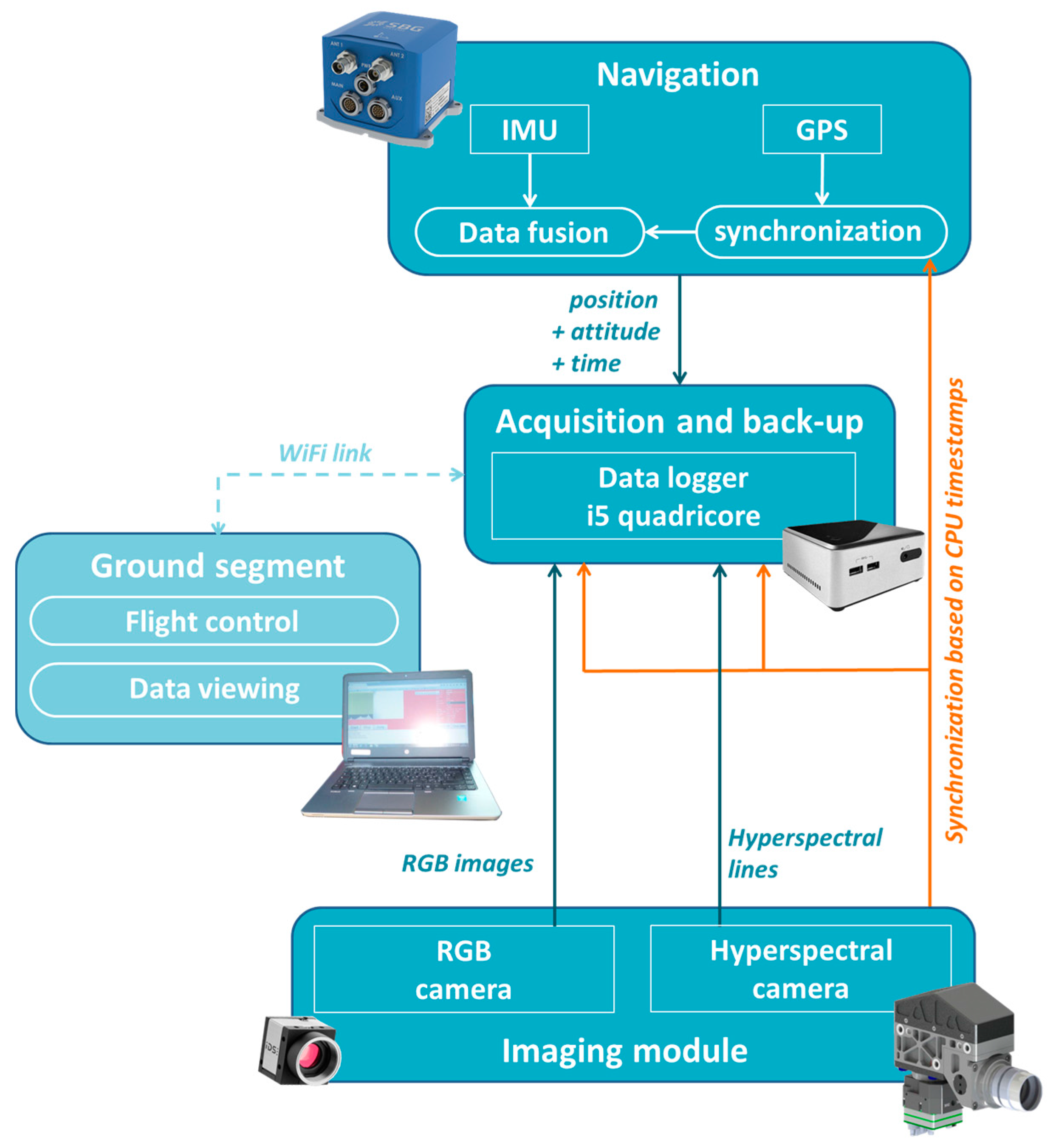
2.3. Proprioceptive Sensors: Navigation Module
2.4. Data Merging
3. Field Operations and Data Processing
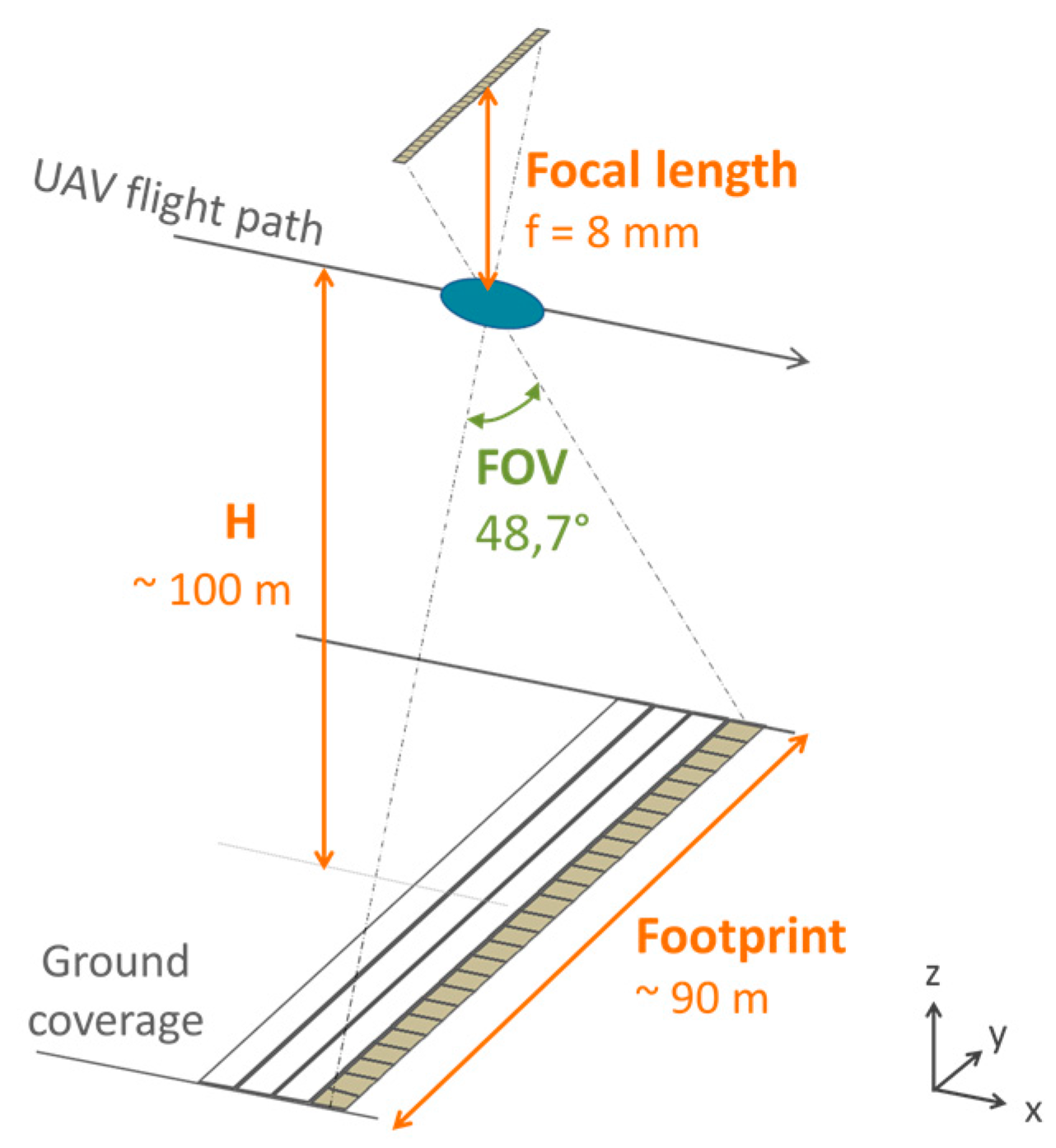
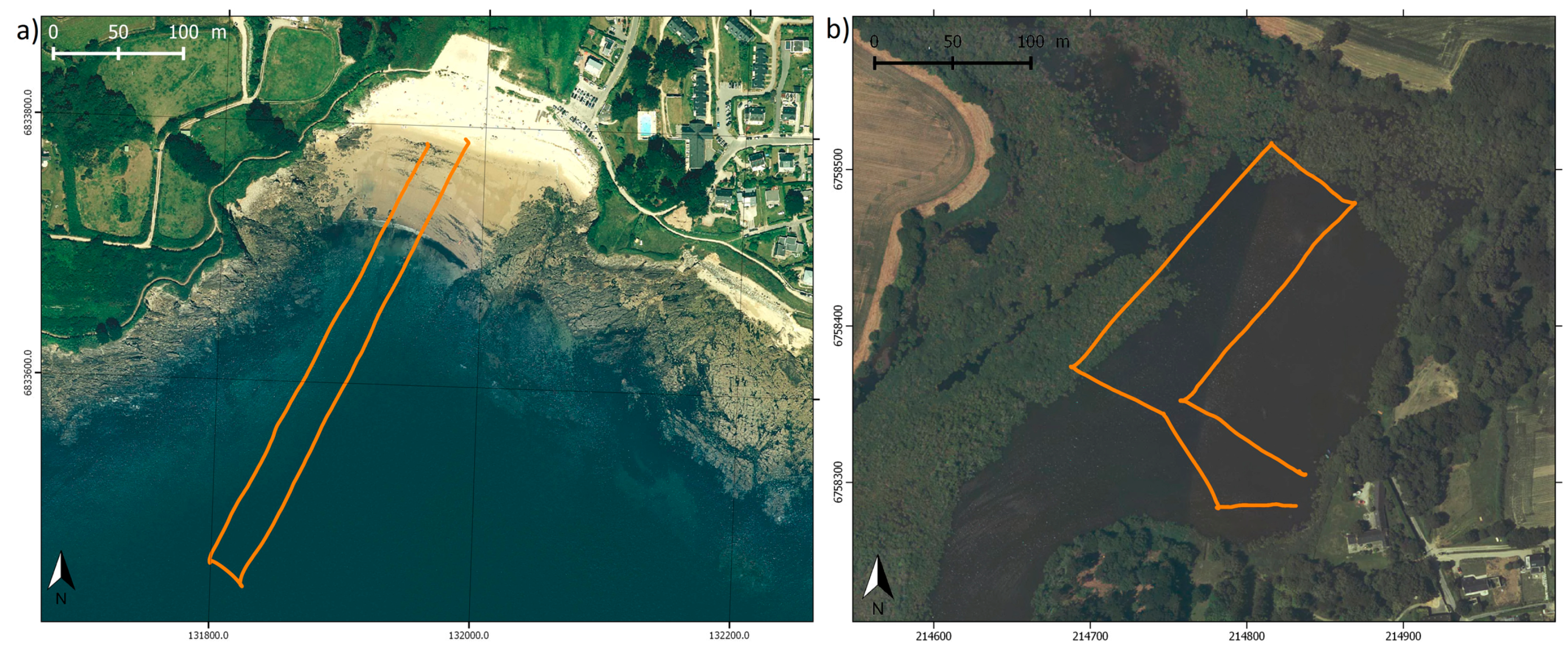
3.1. Practical Considerations for the Survey
- at 100 m of altitude with an imaging swath of 90 m and a cross-track ground resolution about 9 cm (Figure 3). With a speed of about 4 m/s, the along-track ground sampling is about 8 cm. For 6 min of effective flight time, about 13 ha are covered.
- at 50 m of altitude with an imaging swath of 45 m and a cross-track ground resolution about 4.5 cm. With a speed of about 3 m/s, the along-track ground sampling is about 6 cm. For 6 min of effective flight time, about 4.8 ha are covered.
3.2. SfM Photogrammetric Processing
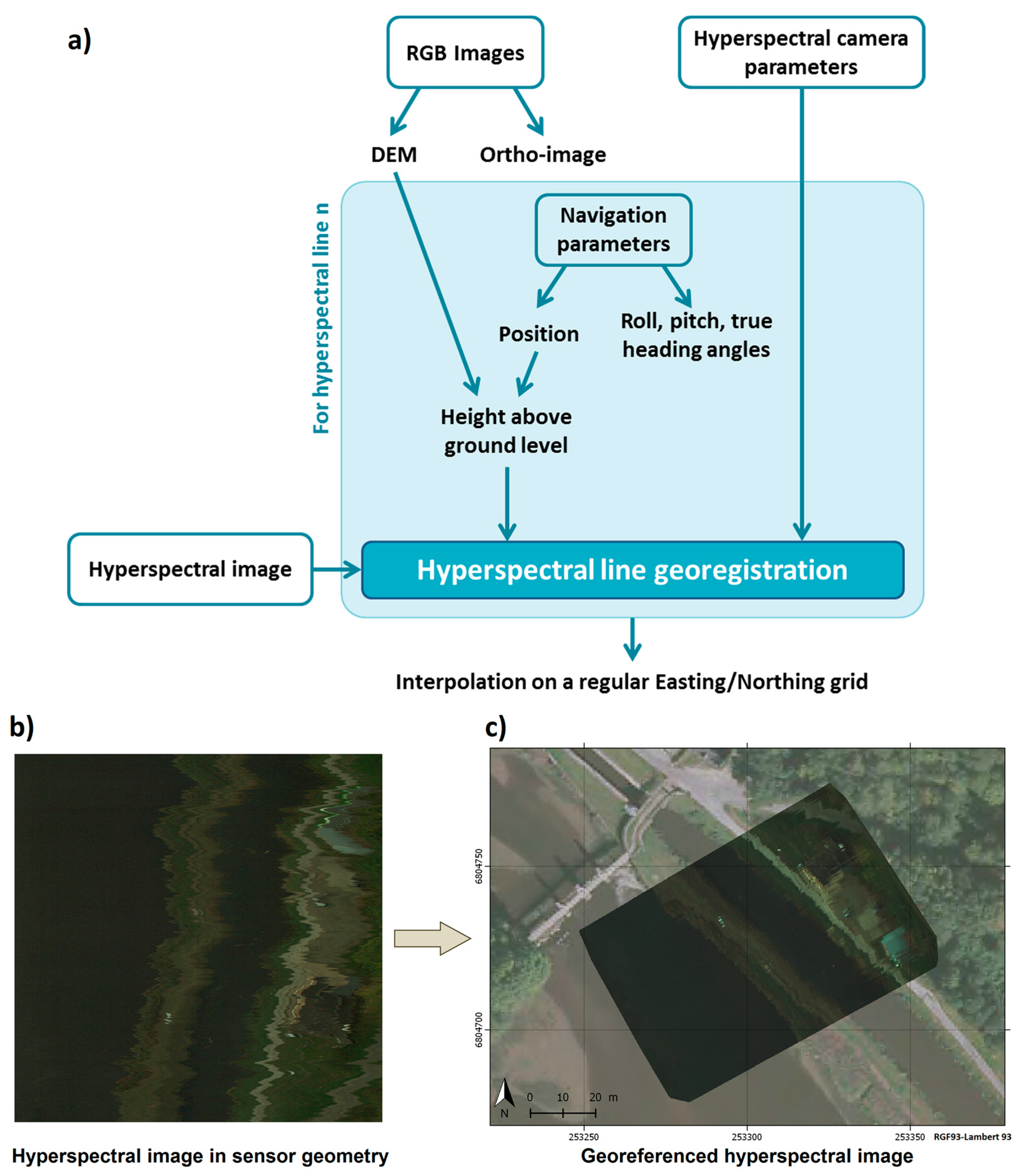
3.3. Geometrical Pre-Processing of Hyperspectral Data
- geometrical acquisition settings: focal length, pixel size, sensor length, mounting offsets;
- the absolute position (X, Y, Z) and orientation (roll, pitch, heading) of the hyperspectral camera, recorded in the image header;
- the DSM of the study area to take into account the true height of the UAV above the terrain.
4. Results
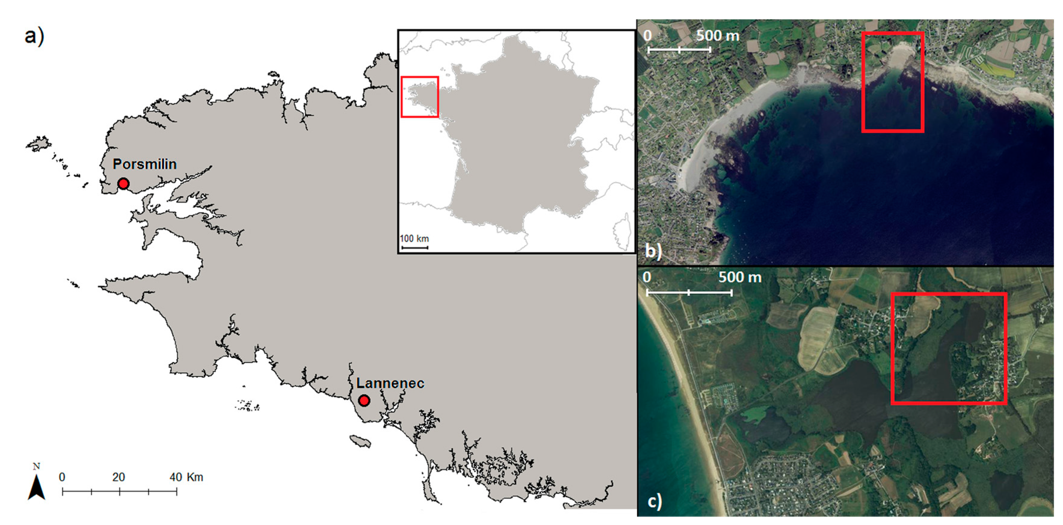
4.1. Study Sites and Surveys
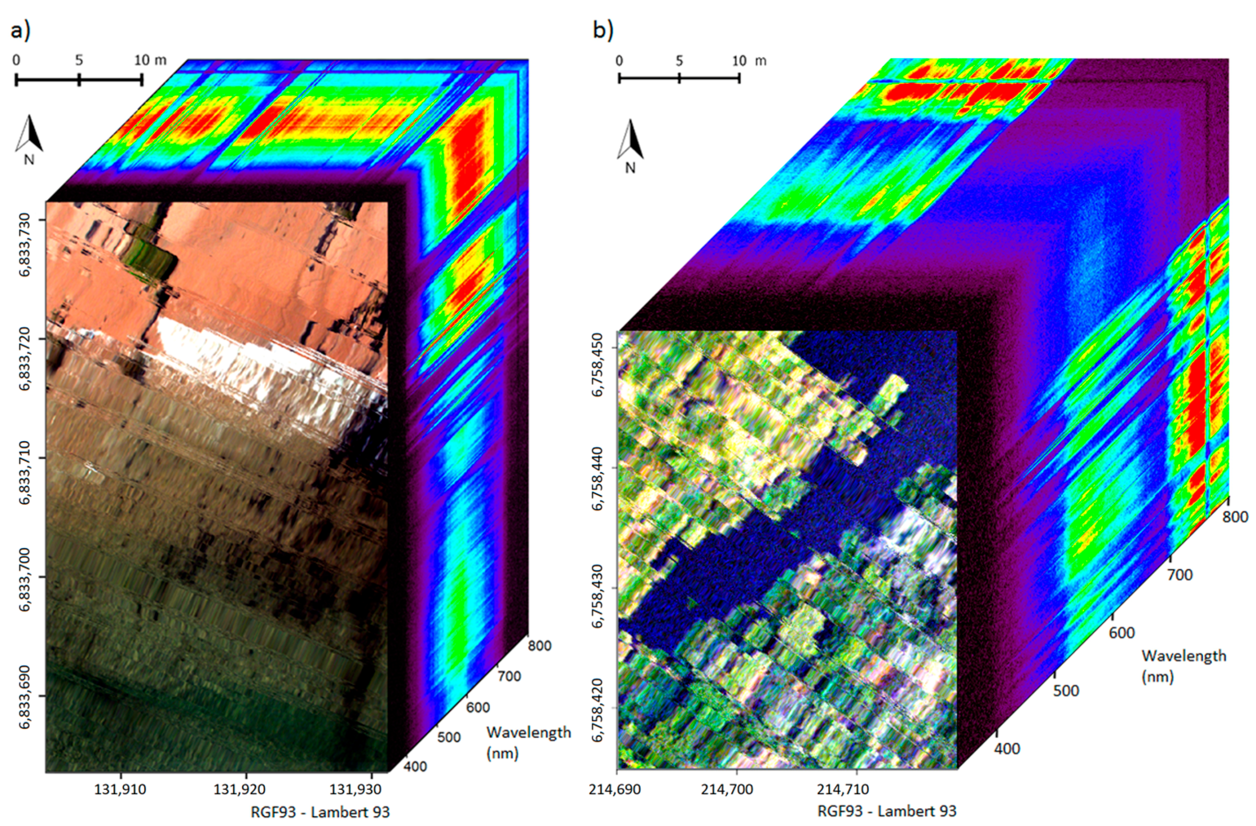
4.2. Results of Hyperspectral Lines Georegistration
5. Discussion
6. Conclusions
Acknowledgments
Author Contributions
Conflicts of Interest
References
- Richardson, M.; Kumar, P. Critical Zone services as environmental assessment criteria in intensively managed landscapes. Earth’s Future 2017, 5, 617–632. [Google Scholar] [CrossRef]
- Asadzadeh, S.; de Souza Filho, C.R. A review on spectral processing methods for geological remote sensing. Int. J. Appl. Earth Obs. Geoinf. 2016, 47, 69–90. [Google Scholar] [CrossRef]
- Gomez, C.; Lagacherie, P.; Coulouma, G. Regional predictions of eight common soil properties and their spatial structures from hyperspectral Vis–NIR data. Geoderma 2012, 189–190, 176–185. [Google Scholar] [CrossRef]
- Chabrillat, S.; Goetz, A.; Krosley, L.; Olsen, H.X. Use of hyperspectral images in the identification and mapping of expansive clay soils and the role of spatial resolution. Remote Sens. Environ. 2002, 82, 431–445. [Google Scholar] [CrossRef]
- Jetz, W.; Cavender-Bares, J.; Pavlick, R.; Schimel, D.; Davis, F.W.; Asner, G.P.; Guralnick, R.; Kattge, J.; Latimer, A.M.; Moorcroft, P.; et al. Monitoring plant functional diversity from space. Nat. Plants 2016, 2, 16024. [Google Scholar] [CrossRef] [PubMed]
- Feret, J.-B.; Asner, G.P. Tree Species Discrimination in Tropical Forests Using Airborne Imaging Spectroscopy. IEEE Trans. Geosci. Remote Sens. 2013, 51, 73–84. [Google Scholar] [CrossRef]
- Gege, P. A case study at Starnberger See for hyperspectral bathymetry mapping using inverse modelling. In Proceedings of the 2014 6th Workshop on Hyperspectral Image and Signal Processing: Evolution in Remote Sensing (WHISPERS), Lausanne, Switzerland, 25–27 June 2014. [Google Scholar]
- Méléder, V.; Launeau, P.; Barillé, L.; Combe, J.-P.; Carrère, V.; Jesus, B.; Verpoorter, C. Hyperspectral imaging for mapping microphytobenthos in coastal areas. In Geomatic Solutions for Coastal Environments; Maanan, M., Robin, M., Eds.; Nova Science: Hauppauge, NY, USA, 2010; Chapter 4; ISBN 978-1-61668-140-1. [Google Scholar]
- Klonowski, W.M.; Fearns, P.R.; Lynch, M.J. Retrieving key benthic cover types and bathymetry from hyperspectral imagery. J. Appl. Remote Sens. 2007, 1, 011505. [Google Scholar] [CrossRef]
- Lee, Z.; Carder, K.L.; Mobley, C.D.; Steward, R.G.; Patch, J.F. Hyperspectral remote sensing for shallow waters: 2. Deriving bottom depths and water properties by optimization. Appl. Opt. 1999, 38, 3831–3843. [Google Scholar] [CrossRef] [PubMed]
- Schimel, D.S.; Asner, G.P.; Moorcroft, P. Observing changing ecological diversity in the Anthropocene. Front. Ecol. Environ. 2013, 11, 129–137. [Google Scholar] [CrossRef]
- Gallay, M.; Eck, C.; Zgraggen, C.; Kaňuk, J.; Dvorný, E. High resolution Airborne Laser Scanning and hyperspectral imaging with a small UAV platform. ISPRS—Int. Arch. Photogramm. Remote Sens. Spat. Inf. Sci. 2016, XLI-B1, 823–827. [Google Scholar] [CrossRef]
- Kosugi, Y.; Mukoyama, S.; Takabayashi, Y.; Uto, K.; Oda, K.; Saito, G. Low-altitude hyperspectral observation of paddy using radio-controlled helicopter. In Proceedings of the IEEE International Geoscience and Remote Sensing Symposium, IGARSS, Vancouver, BC, Canada, 24–29 July 2011; pp. 1748–1751. [Google Scholar]
- Jaakkola, A.; Hyyppä, J.; Kukko, A.; Yu, X.; Kaartinen, H.; Lehtomäki, M.; Lin, Y. A low-cost multi-sensoral mobile mapping system and its feasibility for tree measurements. ISPRS J. Photogramm. Remote Sens. 2010, 65, 514–522. [Google Scholar] [CrossRef]
- Zarco-Tejada, P.J.; Guillén-Climent, M.L.; Hernández-Clemente, R.; Catalina, A.; González, M.R.; Martín, P. Estimating leaf carotenoid content in vineyards using high resolution hyperspectral imagery acquired from an unmanned aerial vehicle (UAV). Agric. For. Meteorol. 2013, 171–172, 281–294. [Google Scholar] [CrossRef]
- Hruska, R.; Mitchell, J.; Anderson, M.; Glenn, N.F. Radiometric and Geometric Analysis of Hyperspectral Imagery Acquired from an Unmanned Aerial Vehicle. Remote Sens. 2012, 4, 2736–2752. [Google Scholar] [CrossRef]
- Uto, K.; Seki, H.; Saito, G.; Kosugi, Y. Characterization of Rice Paddies by a UAV-Mounted Miniature Hyperspectral Sensor System. IEEE J. Sel. Top. Appl. Earth Obs. Remote Sens. 2013, 6, 851–860. [Google Scholar] [CrossRef]
- Bareth, G.; Aasen, H.; Bendig, J.; Gnyp, M.L.; Bolten, A.; Jung, A.; Michels, R.; Soukkamäki, J. Spectral comparison of low-weight and UAV-based hyperspectral frame cameras with portable spectroradiometer measurements. Photogramm. Fernerkund. Geoinf. 2015, 1, 69–79. [Google Scholar] [CrossRef]
- Yang, C.; Everitt, J.H.; Davis, M.R.; Mao, C. A CCD Camera-based Hyperspectral Imaging System for Stationary and Airborne Applications. Geocarto Int. 2003, 18, 71–80. [Google Scholar] [CrossRef]
- Petit, T.; Bajjouk, T.; Mouquet, P.; Rochette, S.; Vozel, B.; Delacourt, C. Hyperspectral remote sensing of coral reefs by semi-analytical model inversion—Comparison of different inversion setups. Remote Sens. Environ. 2017, 190, 348–365. [Google Scholar] [CrossRef]
- Chennu, A.; Färber, P.; Volkenborn, N.; Al-Najjar, M.A.A.; Janssen, F.; de Beer, D.; Polerecky, L. Hyperspectral imaging of the microscale distribution and dynamics of microphytobenthos in intertidal sediments: Hyperspectral imaging of MPB biofilms. Limnol. Oceanogr. Methods 2013, 11, 511–528. [Google Scholar] [CrossRef] [Green Version]
- Aschenbroich, A.; Michaud, E.; Stieglitz, T.; Fromard, F.; Gardel, A.; Tavares, M.; Thouzeau, G. Brachyuran crab community structure and associated sediment reworking activities in pioneer and young mangroves of French Guiana, South America. Estuar. Coast. Shelf Sci. 2016, 182, 60–71. [Google Scholar] [CrossRef]
- Constantin, D. Miniature Hyperspectral Systems. PhD Thesis, École polytechnique fédérale de Lausanne EPFL, Lausanne, Switzerland, 1 September 2017. [Google Scholar]
- Tournadre, V.; Pierrot-Deseilligny, M.; Faure, P.H. UAV Linear Photogrammetry. ISPRS—Int. Arch. Photogramm. Remote Sens. Spat. Inf. Sci. 2015, XL-3/W3, 327–333. [Google Scholar] [CrossRef]
- Kalman, R.E.; Bucy, R.S. New Results in Linear Filtering and Prediction Theory. Trans. ASME—J. Basic Eng. 1961, 83, 95–107. [Google Scholar] [CrossRef]
- Woodget, A.S.; Carbonneau, P.E.; Visser, F.; Maddock, I.P. Quantifying submerged fluvial topography using hyperspatial resolution UAS imagery and structure from motion photogrammetry. Earth Surf. Proc. Landf. 2015, 40, 47–64. [Google Scholar] [CrossRef]
- Javernick, L.; Brasington, J.; Caruso, B. Modeling the Topography of Shallow Braided Rivers Using Structure-from-Motion Photogrammetry. Geomorphology 2014, 213, 166–182. [Google Scholar] [CrossRef]
- Burkart, A.; Aasen, H.; Alonso, L.; Menz, G.; Bareth, G.; Rascher, U. Angular Dependency of Hyperspectral Measurements over Wheat Characterized by a Novel UAV Based Goniometer. Remote Sens. 2015, 7, 725–746. [Google Scholar] [CrossRef] [Green Version]
- Aasen, H.; Burkart, A.; Bolten, A.; Bareth, G. Generating 3D hyperspectral information with lightweight UAV snapshot cameras for vegetation monitoring: From camera calibration to quality assurance. ISPRS J. Photogramm. Remote Sens. 2015, 108, 245–259. [Google Scholar] [CrossRef]
- Rehak, M.; Skaloud, J. Applicability of New Approaches of Sensor Orientation to Micro-Aerial Vehicles. ISPRS—Int. Arch. Photogramm. Remote Sens. 2016, III-3, 441–447. [Google Scholar] [CrossRef]
- Barbieux, K.; Constantin, D.; Merminod, B. Correction of airborne pushbroom images orientation using bundle adjustment of frame images. ISPRS—Int. Arch. Photogramm. Remote Sens. 2016, XLI-B3, 813–818. [Google Scholar] [CrossRef]


| Sensors and Related Equipment | Weight |
|---|---|
| Headwall Micro-Hyperspec® camera | 680 g |
| Hyperspectral camera Schneider® lens | 90 g |
| iDS© uEye RGB camera | 52 g |
| RGB camera Tamron® lens | 39 g |
| SBG System® Ekinox-D IMU | 600 g |
| Dual GNSS antenna (without frame) | 2 × 10⁵ g |
| Intel® NUC | 450 g |
| Onboard package LiPo battery | 230 g |
| Waterproof chamber and cables | 2040 g |
| Total weight: | 4.39 kg |
| Porsmilin Beach | Lannénec Pond | |
|---|---|---|
| Flight altitude | 50 m | 100 m |
| Cross-track swath | 45 m | 90 m |
| Flight lines overlapping | 33% | 33% |
| Spacing between flight lines | 30 m | 60 m |
| Ground spatial resolution | 4.5 cm | 9 cm |
| Speed | 3 m/s | 4 m/s |
| Along-track ground sampling | 6 cm | 8 cm |
| Hyperspectral camera gain | 5 | 6 |
| Hyperspectral acquisition rate | 50 Hz | 50 Hz |
| Flight duration | 6′15″ | 5′40″ |
| Distance of exploitable recording | 750 m | 500 m |
| Number of exploitable flight lines | >10,000 | >8000 |
| Covered area | 2.8 ha | 3.7 ha |
| Data volume | >5 Gb | >4 Gb |
© 2018 by the authors. Licensee MDPI, Basel, Switzerland. This article is an open access article distributed under the terms and conditions of the Creative Commons Attribution (CC BY) license (http://creativecommons.org/licenses/by/4.0/).
Share and Cite
Jaud, M.; Le Dantec, N.; Ammann, J.; Grandjean, P.; Constantin, D.; Akhtman, Y.; Barbieux, K.; Allemand, P.; Delacourt, C.; Merminod, B. Direct Georeferencing of a Pushbroom, Lightweight Hyperspectral System for Mini-UAV Applications. Remote Sens. 2018, 10, 204. https://doi.org/10.3390/rs10020204
Jaud M, Le Dantec N, Ammann J, Grandjean P, Constantin D, Akhtman Y, Barbieux K, Allemand P, Delacourt C, Merminod B. Direct Georeferencing of a Pushbroom, Lightweight Hyperspectral System for Mini-UAV Applications. Remote Sensing. 2018; 10(2):204. https://doi.org/10.3390/rs10020204
Chicago/Turabian StyleJaud, Marion, Nicolas Le Dantec, Jérôme Ammann, Philippe Grandjean, Dragos Constantin, Yosef Akhtman, Kevin Barbieux, Pascal Allemand, Christophe Delacourt, and Bertrand Merminod. 2018. "Direct Georeferencing of a Pushbroom, Lightweight Hyperspectral System for Mini-UAV Applications" Remote Sensing 10, no. 2: 204. https://doi.org/10.3390/rs10020204
APA StyleJaud, M., Le Dantec, N., Ammann, J., Grandjean, P., Constantin, D., Akhtman, Y., Barbieux, K., Allemand, P., Delacourt, C., & Merminod, B. (2018). Direct Georeferencing of a Pushbroom, Lightweight Hyperspectral System for Mini-UAV Applications. Remote Sensing, 10(2), 204. https://doi.org/10.3390/rs10020204