
Using Specification and Description Language for Life Cycle Assesment in Buildings


1
Statistics and Operations Department, Universitat Politècnica de Catalunya, Barcelona-Tech, 08034 Barcelona, Spain
2
Polyhedra Tech SL, 08026 Barcelona, Spain
*
Author to whom correspondence should be addressed.
Sustainability 2017, 9(6), 1004; https://doi.org/10.3390/su9061004
Submission received: 10 March 2017
/
Revised: 15 May 2017
/
Accepted: 5 June 2017
/
Published: 10 June 2017
(This article belongs to the Section Sustainable Engineering and Science)
Abstract
:The definition of a Life Cycle Assesment (LCA) for a building or an urban area is a complex task due to the inherent complexity of all the elements that must be considered. Furthermore, a multidisciplinary approach is required due to the different sources of knowledge involved in this project. This multidisciplinary approach makes it necessary to use formal language to fully represent the complexity of the used models. In this paper, we explore the use of Specification and Description Language (SDL) to represent the LCA of a building and residential area. We also introduce a tool that uses this idea to implement an optimization and simulation mechanism to define the optimal solution for the sustainability of a specific building or residential.
1. Introduction
Currently, there is worldwide awareness of the global increase in energy consumption and the limited amount of resources available to provide energy to citizens and enterprises. This creates a huge energy demand and the need to define a new economy and transition methods to increase energy savings [1]. Considering more effective methods to reduce energy consumption in residential and commercial areas is strongly related to building efficiency, which has a great impact on electricity consumption. Although electricity represents only a part of the total energy consumption, it clearly reflects the importance of the building in the global impact.
In the USA, the residential sector represents approximately 38% of the electricity consumed and in the commercial area, approximately 36% [2]. The Life Cycle Assesment (LCA) in a building or an urban area helps to obtain a clear image of all processes involved in the planning, construction, use, and deconstruction of a house. This holistic view can assist in the reduction of the impact, taking care of the economic, social, and environmental aspects in a cradle to cradle approach [3]. From an environmental point of view, reducing energy consumption would have a great impact in decreasing the environmental impacts. In addition, the analysis of the LCA for houses has a great impact on energy consumption in all sectors, not only in houses, but also shows a foreseeable greater impact on the residential and commercial sectors that represent a huge part of the total. For example, all materials that must be used in a building must be transported from several different origins to its final destination of the building. By incorporating these parameters in the model, we can also reduce the emissions from transportation, which are huge.
2. State of the Art
Building or residential area LCA is complex, mainly because it needs to use powerful tools to scope the complex dynamics of the environment and the energy. Several problems arise with this type of analysis and includes the amount and the diversity of the data that must be used, and the fact that this area utilizes different specialists working with different skills in multidisciplinary teams. Mainly, these problems are related to the choice of unit of the analysis and the methodological and practical approaches used [4]. In this context, some approaches have been undertaken to improve the LCA application in architecture [5,6]. A complete review of the development of the LCA in the field of architecture can be found in the studies presented by [7,8].
By 31 December 2020, EU directive 2010/31/EU requires that all new buildings must be nearly zero-energy buildings (nZEB). The aim of this directive is to incorporate concepts for reducing their impact on the environment [9]; thus, the member states must also complete the thresholds and policies to update their building stock [10,11,12,13].
Member states have launched a series of projects, actions, and policy guidelines to specify the optimal cost-performance actions to achieve the objectives proposed by the regulation on energy rehabilitation (Royal Decree 235/2013). This allows researchers to check which urban areas are in the greatest need of rehabilitation and/or that suffer from so-called “energy poverty” [14]. Furthermore, several European and national projects have been proposed [15,16] to provide funding for initiatives which, in addition to addressing the issue of energy efficiency either for new construction or rehabilitation, also include the impact of construction on the environment; that is to say, be capable of conducting a LCA (Life Cycle Assesment) of the building and thereby ascertain its associated impacts. Such concepts must be addressed to complete the analysis, not solely in terms of energy and economic cost.
To perform a comprehensive study of sustainability, one must include the proposed European standards developed by the CEN TC 350 Working Group, and implemented nationally via Standard UNE EN 15643 on the Sustainability of Construction Works [17]. This set of standards describes and specifies the impacts that must be considered (environmental, economic and social impacts), details indicators, and proposes methodologies.
If we consider the criteria and objectives that must be achieved based on the above-mentioned standards, programs and applications must be employed to simulate energy consumption, calculate economic and environmental impacts, and conduct a complete LCA.
No global proposals exist for analyzing certain parameters. Often the designer or engineer has to invest a significant amount of time designing a virtual model just to study a few design iterations to identify a good solution. The designer is not in a position to ensure that the best solution is adopted, or at least one of the best solutions, without analyzing all, or an accurately selected subset, of the possibilities. In addition, most commercial simulation software packages allow for a building’s annual energy analysis to be calculated, but do not perform any kind of optimization for the process. Hence, none of the results for the previous steps, such as the design, construction, or demolition processes, are optimized. Efforts have been made to develop approaches and methods for assessing buildings [18], methods for integrating daylight and thermal efficiency [19,20,21], photovoltaic systems [22], and multi-objective optimization systems into urban design [23], which consider several aspects when creating an energy optimization system.
Languages that are commonly used for programming simulators or optimization tools are C++, C#, Fortran, Java and Delphi, among many others. The use of different languages may cause problems with integration, model determination and understanding between researchers from different disciplines, as not everyone understands the low-level code finally used. One of the proposals presented in this work is the use of a formal language to simplify model definition and use.
The use of formal languages, such as Discrete Event System Specification (DEVS) [24], Specification and Description Language (SDL) [25,26], or Petri nets [27], is without a doubt one of the best solutions. These languages allow for an easy integration and communication of ideas related to the model with the other members of the team. Additionally, these tools improve interoperability with other models (co-simulation) and promotes cooperation. Examples of recent works that explore the use of official languages in this area are [28,29], which explore the use of the co-simulation approach for calculating building HVAC systems (heating, ventilation, and air conditioning). To represent this LCA, we used a discrete simulation model formalized using Specification and Description Language (SDL). In this area, several approaches exist, mainly ruled by the tools used. Classical languages like GPSS/H® [30], Slam II® [31], or others considered more modern like Simprocess® [32], Arena [33], or SIMIO [34], among many others, can be used. These software packages allow a complete definition of the model behavior, structure, time and representation; however, once the model is defined in one of these simulation packages, it is often difficult to migrate to another. All specialists who interact with the model must also understand how the tool works. In this context, the use of formal language to represent the model and to later use a specific tool to implement the model is necessary, even more so if the model is complex or the personnel working on the model own different forms or, do not know how to implement the model in the specific tool selected to perform its implementation.
Programming libraries and infrastructures exist that allow for the definition of a simulation model following a formal language. The tools related to DEVS [35,36,37] and PetriNets formalisms [27] often represent an excellent alternative to define and implement a simulation model based on Petri nets or DEVS. Specifically to model buildings and their related processes, several experiences exist using DEVS as a language, based on the BIM (Building Information Modeling) philosophy, see [28,38], but no experiences trying to model the entire LCA of a house or urban area have been found.
SDL is not new for modeling energy-related issues. [39] presented two complementary approaches to specify energy aspects during the design phase of wireless networks, but like DEVS, no studies that model the LCA of a building exist.
In this paper, we describe our experience of using SDL to describe the main processes that define the LCA of a building and show how to take advantage of a formal representation to expand the model implementation easily over different platforms. The paper is organized as follows: in Section 3, we describe the SDL based model we use; in Section 4, we discuss how to implement this model; in Section 5, we describe how to execute the model on the web using a cloud infrastructure. Finally, Section 6 contains our conclusions.
3. Methodology
One of the aims of this research was to describe, as formally as possible, the structure and behavior of the LCA of a building. This goal was crucial as the people involved are diverse and come from many different backgrounds. To address this issue, we used SDL to formally define the model. The use of the SDL language afforded maximum flexibility to integrate new processes and procedures to the system in a co-simulation scenario [29]. Using a graphical formal language allowed nonspecialized technicians access to the programming details of the model and definitively contributed to the validation and verification processes. In addition, the explanation of the model itself was more intuitive, simple, and direct than using a programming language such as C or Java. Thus, the group can share the model, making it much easier to understand and detect errors, as well as propose improvements.
3.1. Specification and Description Language
In this section, we do not describe specifically how SDL behaves, more information on this language can be found in [25,26]. However, we want to note that the graphical capabilities, the completeness, and lack of language ambiguity makes it a great candidate to formally define any kind of simulation model.
Specification and Description Language (SDL) is an object-oriented, formal language defined by The International Telecommunications Union-Telecommunications Standardization Sector [25], formerly Comité Consultatif International Telegraphique et Telephonique (CCITT), in recommendation Z.100. The language is intended for the specification of complex, event-driven, real-time, and interactive applications involving many concurrent activities that communicate using discrete signals. SDL uses four levels to describe model behaviors: system, blocks, processes, and procedures, see Figure 1.
With SDL, it is possible to generate unambiguous code from the specification; thus, the ideal to avoid the implementation process and assure that the current implementation of the model represented, as closely as possible, the model proposed. SDL has different advantages: it is a non-ambiguous language, graphical, and standardized (the ITU-T), and as SDL allows the definition of distributed systems, the resulting model can be executed over different computers without any modification of the model representation. This allows a process where a model can be implemented and executed in distributed, parallel, or sequential ways without any modification; the only issue is selecting the proper tool to perform the execution or implementation. SDL is designed to assure its compatibility with Unified Modeling Language (UML) and Message Sequence Chart (MSC) (see document Z.105 of the ITU that describes how to use Message Sequence Charts in combination with SDL). SDL, like UML, is a standard of the ITU, and one of the main concerns is assuring compatibility between the different proposed standards. As SDL is compatible with some extensions that are proposed to UML, such as SysML or AUML, that extends the language to represent intelligent agents.
The different model concepts that the SDL formalism describes are (i) Structure: system, blocks, processes and processes hierarchy; (ii) Communication: signals, along with the parameters and channels that the signals use to travel; (iii) Behavior: defined through the different processes; (iv) Data: based on Abstract Data Types (ADT); and (v) Inheritances: to describe the relationships between, and specialization of, the model elements.
System diagrams, i.e., block diagrams describing the model structure, represent hierarchical decompositions of the different model elements; some good examples can be reviewed in [26]. A process diagram defines the behavior of the agents when a specific signal is received and uses different graphical elements to represent its behavior.
Start. ![Sustainability 09 01004 i001]() This element defines the initial condition for a PROCESS diagram.
This element defines the initial condition for a PROCESS diagram.
 This element defines the initial condition for a PROCESS diagram.
State. ![Sustainability 09 01004 i002]() The state element contains the name of a state. This element defines the states of behavioral diagrams, such as PROCESS diagrams.
The state element contains the name of a state. This element defines the states of behavioral diagrams, such as PROCESS diagrams.
 The state element contains the name of a state. This element defines the states of behavioral diagrams, such as PROCESS diagrams.
Input. ![Sustainability 09 01004 i003]() Input elements describe the type of events that can be received by the process. All branches of a specific state start with an Input element because an object only changes its state when a new event is received.
Input elements describe the type of events that can be received by the process. All branches of a specific state start with an Input element because an object only changes its state when a new event is received.
 Input elements describe the type of events that can be received by the process. All branches of a specific state start with an Input element because an object only changes its state when a new event is received.
Create. ![Sustainability 09 01004 i004]() This element allows the creation of an agent.
This element allows the creation of an agent.
 This element allows the creation of an agent.
Task. ![Sustainability 09 01004 i005]() This element allows the interpretation of informal texts or programming code. In this paper, following SDL-RT (PragmaDev SARL, 2006), we used C code.
This element allows the interpretation of informal texts or programming code. In this paper, following SDL-RT (PragmaDev SARL, 2006), we used C code.
 This element allows the interpretation of informal texts or programming code. In this paper, following SDL-RT (PragmaDev SARL, 2006), we used C code.
Procedure call. ![Sustainability 09 01004 i006]() These elements perform a procedure call. A PROCEDURE can be defined in the last level of the SDL language and used to encapsulate pieces of the model for reuse.
These elements perform a procedure call. A PROCEDURE can be defined in the last level of the SDL language and used to encapsulate pieces of the model for reuse.
 These elements perform a procedure call. A PROCEDURE can be defined in the last level of the SDL language and used to encapsulate pieces of the model for reuse.
Output. ![Sustainability 09 01004 i007]() Output elements describe the types of signals to be sent, the parameters that the signal carries, and the destination. If ambiguity about the signal destination exists, communication can be directed by specifying destinations using a processing identity value (PId), an agent name, or using the sentence via path. If there is more than one path and no specific output is defined, an arbitrary one is used. The destination value can be stored in a variable for later use. Four PId expressions can be used: (i) self, an agent’s own identity; (ii) parent, the agent that created the agent (Null for initial agents); (iii) offspring, the most recent agent created by the agent; and (iv) sender, the agent that sent the last signal input (null before any signal received).
Output elements describe the types of signals to be sent, the parameters that the signal carries, and the destination. If ambiguity about the signal destination exists, communication can be directed by specifying destinations using a processing identity value (PId), an agent name, or using the sentence via path. If there is more than one path and no specific output is defined, an arbitrary one is used. The destination value can be stored in a variable for later use. Four PId expressions can be used: (i) self, an agent’s own identity; (ii) parent, the agent that created the agent (Null for initial agents); (iii) offspring, the most recent agent created by the agent; and (iv) sender, the agent that sent the last signal input (null before any signal received).
 Output elements describe the types of signals to be sent, the parameters that the signal carries, and the destination. If ambiguity about the signal destination exists, communication can be directed by specifying destinations using a processing identity value (PId), an agent name, or using the sentence via path. If there is more than one path and no specific output is defined, an arbitrary one is used. The destination value can be stored in a variable for later use. Four PId expressions can be used: (i) self, an agent’s own identity; (ii) parent, the agent that created the agent (Null for initial agents); (iii) offspring, the most recent agent created by the agent; and (iv) sender, the agent that sent the last signal input (null before any signal received).
Decision. ![Sustainability 09 01004 i008]() These elements describe bifurcations. Their behavior depends on how the related question is answered.
These elements describe bifurcations. Their behavior depends on how the related question is answered.
 These elements describe bifurcations. Their behavior depends on how the related question is answered.
The last level of the SDL language (PROCEDURE diagrams) allows the description of procedures that can be used in the PROCESS diagrams through the procedure calls ![Sustainability 09 01004 i006]() . These diagrams are very similar to the PROCESS diagrams with the exception that they do not need state definitions.
. These diagrams are very similar to the PROCESS diagrams with the exception that they do not need state definitions.
. These diagrams are very similar to the PROCESS diagrams with the exception that they do not need state definitions.3.2. The Model
Here, the model is described with its main elements to understand the benefits of the approach. For a detailed description of the model please refer to [40]. Figure 2 shows the first level of the building simulation model. Four main blocks represent the environment, the building, the compensation and the waste treatments.
In this model, the structure and behavior of the building LCA are described as formally as possible. The detailed description of the model helps in the validation process. The validation was done by a team of specialists on the system, architects, and engineers who clearly understand the system. This type of validation (for validation of the conceptual model, see [41]) is needed to depict the relationships between all the components that the experts depict as important for system behavior. Once this has been achieved, the structure of the model is complete, and one can start analyzing the model behavior.
Every building is connected to energy (isolated or in a network) and to social networking (the residents), and these concepts must be modeled to complete the cycle, an idea already introduced in Cradle to Cradle [3] where we face a new paradigm of design (see Figure 3).
This vision of the reality is characterized in the SDL model presented in Figure 2. The B1_Environment block encapsulates all processes related to the environment. For example, it represents the amount of radiation that the building receives, the hydrologic conditions, and so on. All of the information calculated in this BLOCK is sent to the B1_building block through data that represents all of the required weather information. B1_Building is the main BLOCK of the model as it represents the main processes that rule the behavior and structure of the building. B1_compensation encapsulates the processes necessary to deliver the energy consumed by the building and to neutralize the environmental impacts (through the process of energy generation, for example, with solar photovoltaic or CO2 gas absorption systems).
B1_WasteTreatment represents the processes related to waste disposal. Each of the different blocks of the model is decomposed into a single process.
The main variables that the model uses are detailed in Table 1. The BIM model is represented by the Energy+ format, idf files, and climatic information is represented on the andepw files. Several other factors (variables) can be modified in the model to define the scenarios to be executed.
The main output variables are shown in Table 2 and represent only a few subsets of the information obtained from the model that is stored in a text file following an XML format.
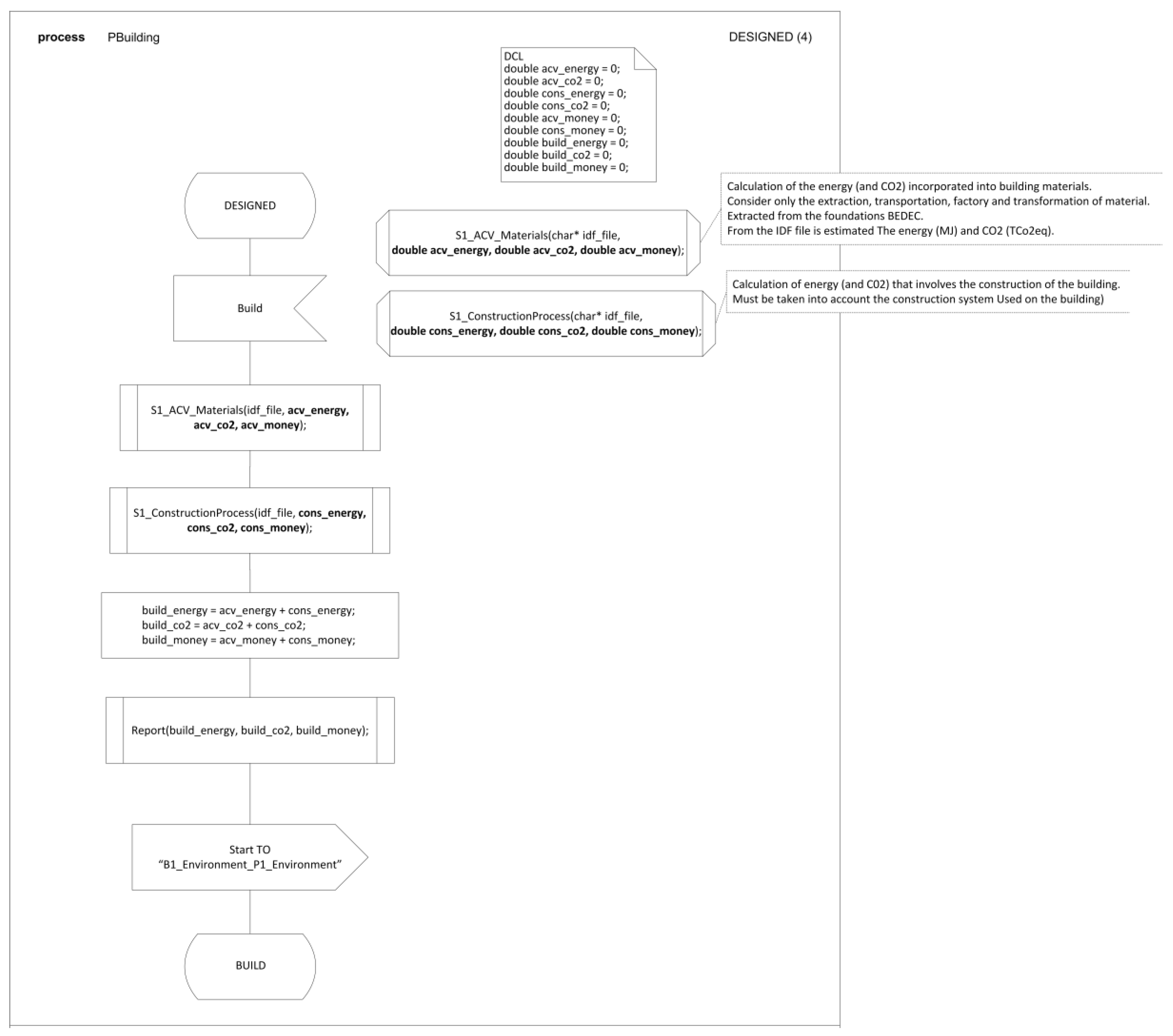
An example of the SDL PROCESS that rules the model behavior (Figure 4) shows the behavior for the DESIGNED state of the P1_Building PROCESS. This is the process responsible for the representation of the entire life of the building, from the design phase to the destruction and recycling phases. In this case, the building starts in the DESIGNED state, representing the fact that a specific design has been selected for the building and the building process can begin. The BUILD state represents the fact that the building has been constructed and can be used. The USED state represents the fact that the useful life of the building is over and it needs to be demolished. Finally, the DESTROYED state represents the fact that the building has been demolished. Every one of these states has its own calculations and logistics; some of them using external calculus engines in a co-simulation scenario.
The standard ISO 14040 was adopted for the LCA and impact method analysis. Specifically, impact method ECO 99 [44] was used.
Auxiliary variables defined in DCL allowed us to represent the parametrizations for a house in an experiment, which helps in defining the experimental design. The main model elements are represented in PROCESS diagrams; PROCEDURES are used to calculate the building energy consumed (this part of the model can analyze and optimize different HVAC systems based on the COP and the performance of each active climate machine where we know the kWh/m2 energy consumption required to reach the thermal comfort for each situation studied). Once the model is correct, the final users can only modify the DCL’s of the model by using a cloud infrastructure.
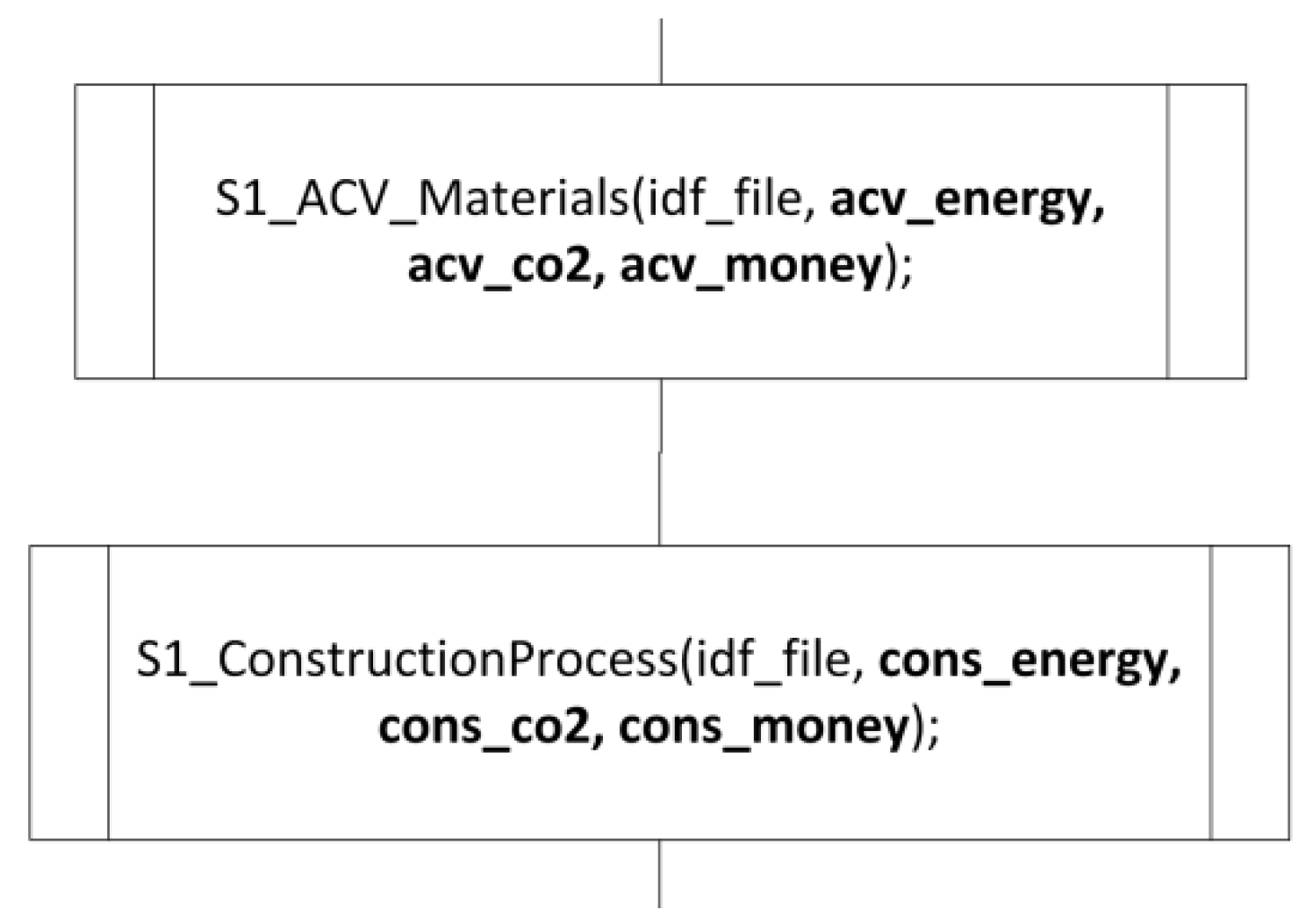
We can analyze the behavior of the PROCEDURES (that use a database to calculate the environmental, social, and economic aspects of the materials used), and the systems applied to build the model. The S1_ACV-Materials PROCEDURE analyzes the environmental impacts and the economic and social costs related to materials. The S1_ConstructionProcess PROCEDURE analyzes the construction process, as seen in Figure 5.
One can connect, thanks to the SDL modularity, several buildings to define an urban area. In this case, the model only needs to define the communication mechanisms to be used (on the model itself). The execution of the model that contains several buildings provides information of an urban area, instead of providing information of just a single isolated building.
Co-simulation techniques can be applied on PROCEDURES to calculate the energy impacts using state-of-the-art calculus engines like Energy+ [45]. Heuristic optimization is used, based on Hill Climbing, Simulated Annealing, or NSGAII algorithms. These optimization techniques allow the dramatic reduction of the number of scenarios to be executed, whilst still obtaining a good answer. The time needed to obtain an answer for an experimental design can be large, as suggested in [46] who presented an example of an execution of a real experiment in a distributed scenario. The criteria used was based on an expression that combined the different variables that were interesting in the definition of the LCA. This expression was defined by the user in the software we used (see next section), which defined the experimental design and how it was executed.
4. Results
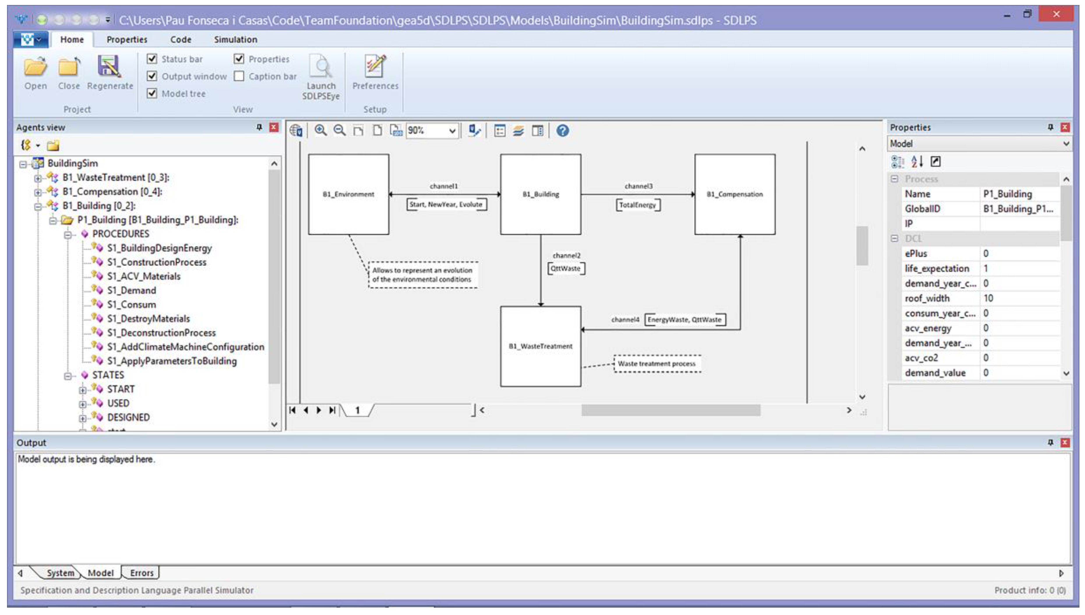
The model was implemented using SDLPS software [47,48]. SDLPS was built using C++ and C languages. The model code (written in C for the tasks and procedures of the SDL blocks) was used through a Dynamic Link Library (DLL). The model was defined directly using Microsoft Visio®, following the standard implemented on the 2013 version as SDLPS understands this format and transforms it to an XML format that represents the SDL model. This coding implies that the model can be validated and verified by reviewing the graphic diagrams in Microsoft Visio®. This property dramatically simplifies the interaction between the different actors involved in the project. Figure 6 shows the SDLPS loaded with a model for a building.
5. Executing on the Cloud: NECADA
The model was defined using SDL and all team members were aware of the hypotheses used in it. However, in this type of model, parametrization is a key element that needs to be reviewed to carefully assure that the data introduced are accurate and correct. Additionally, once the developing team has agreed on the validity of the model (in some sense the model is accredited), no modification is needed until the underlying hypotheses are modified. In that case, the parametrization proposed on the SDL diagrams trough the DCL’s is the key element in defining the different scenarios to be conducted. This parametrization can be done by third party teams who do not have to be directly connected with the model development.
5.1. Description of the Current Platform
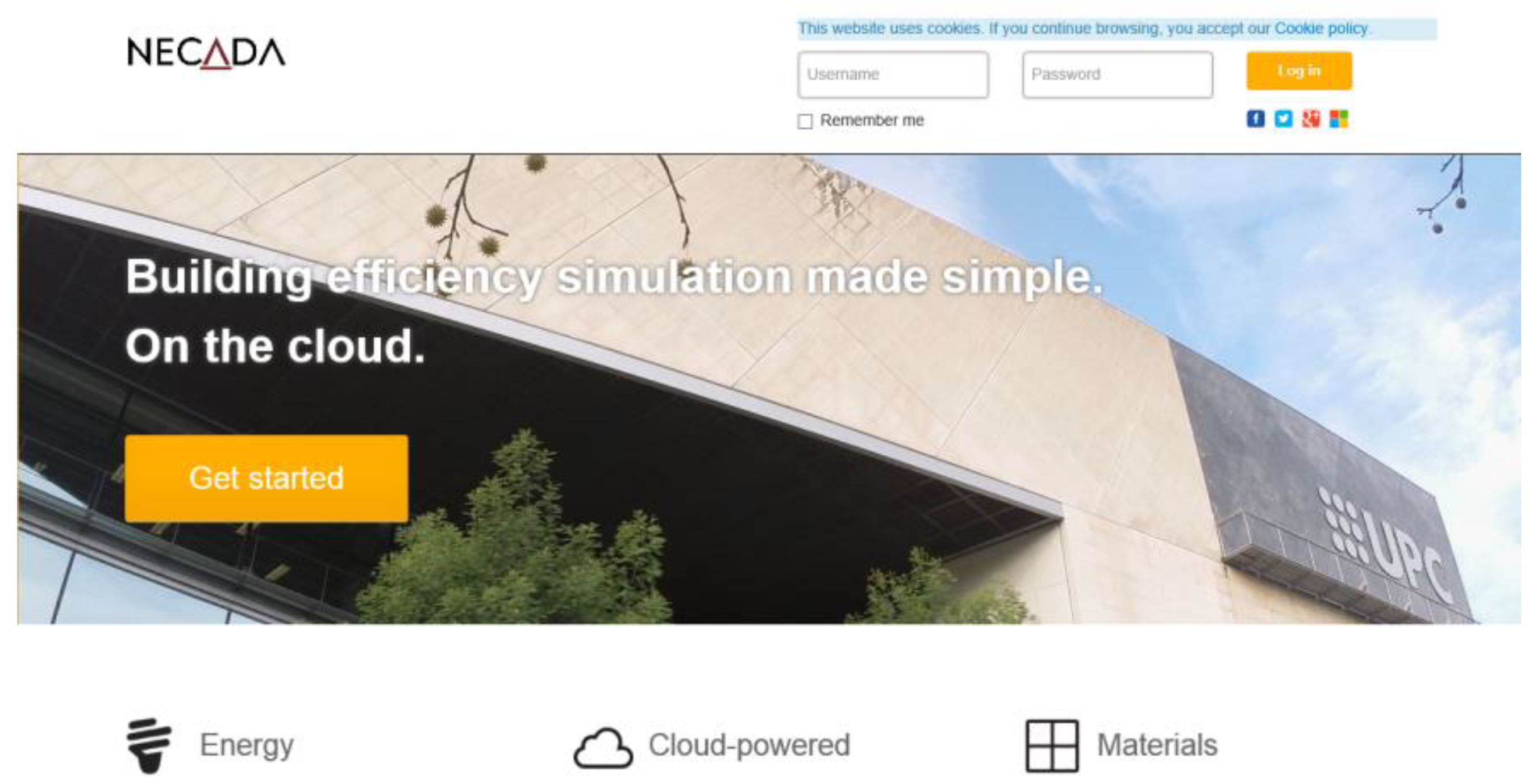
To simplify parametrization and error reduction, a Cloud service named NECADA® was developed to allow model parametrization and execution. Figure 7 shows the login screen of the NECADA cloud solution.
NECADA manages the parametrization of the experimental design to be executed and sends it to SDLPS, which executes the LCA building model. SDLPS acts as a simulation server executing the experiments defined over the web; Figure 8 shows the public projects of the NECADA website.
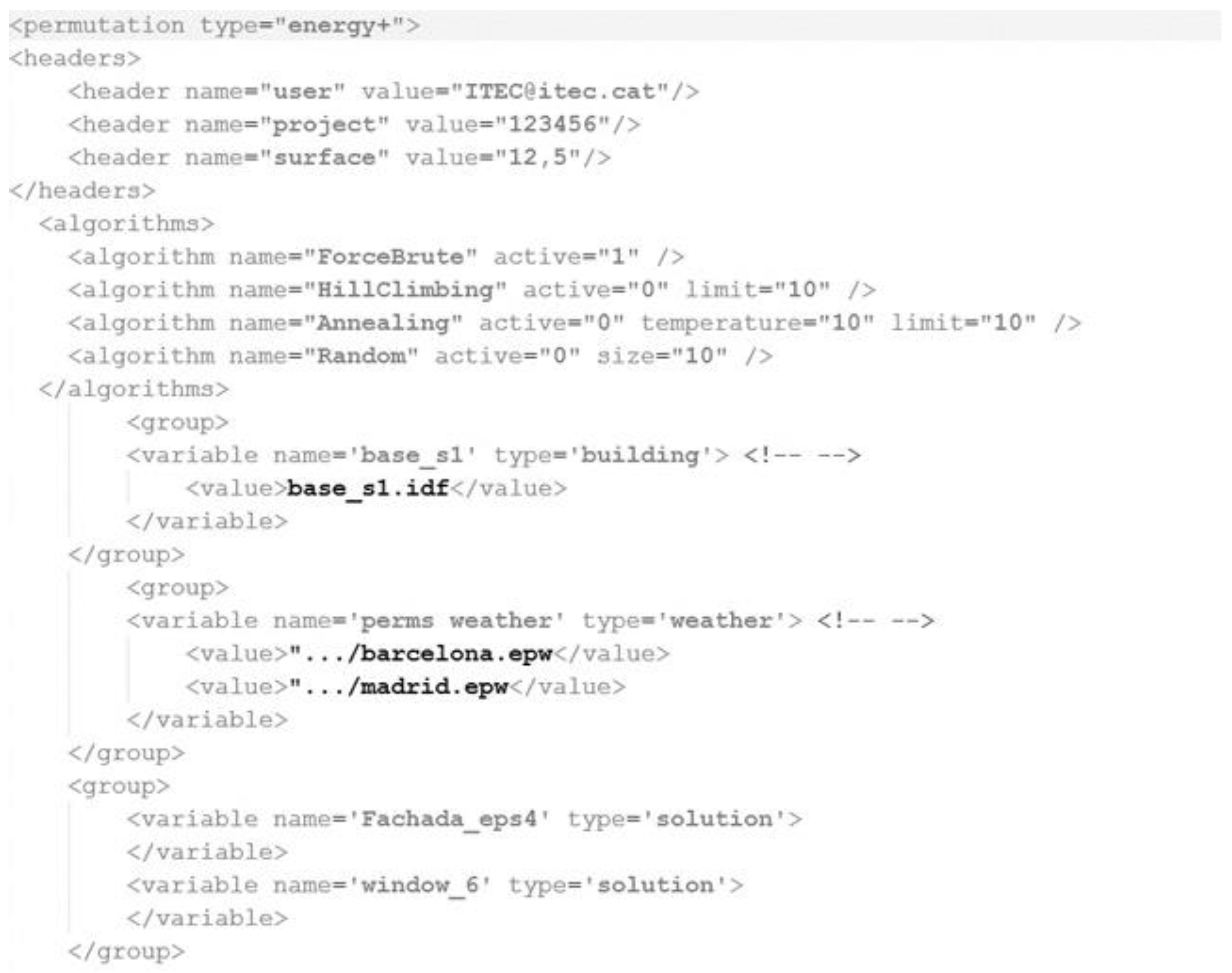
Each one of these projects owns specific building models (the building geometry), based on the BIM methodology [49], materials, constructing solution, weathers, and orientations that can be permutated on the experiments. These permutations are the key elements that are defined by the analyst since it defines the space to be explored by the model (Figure 9).
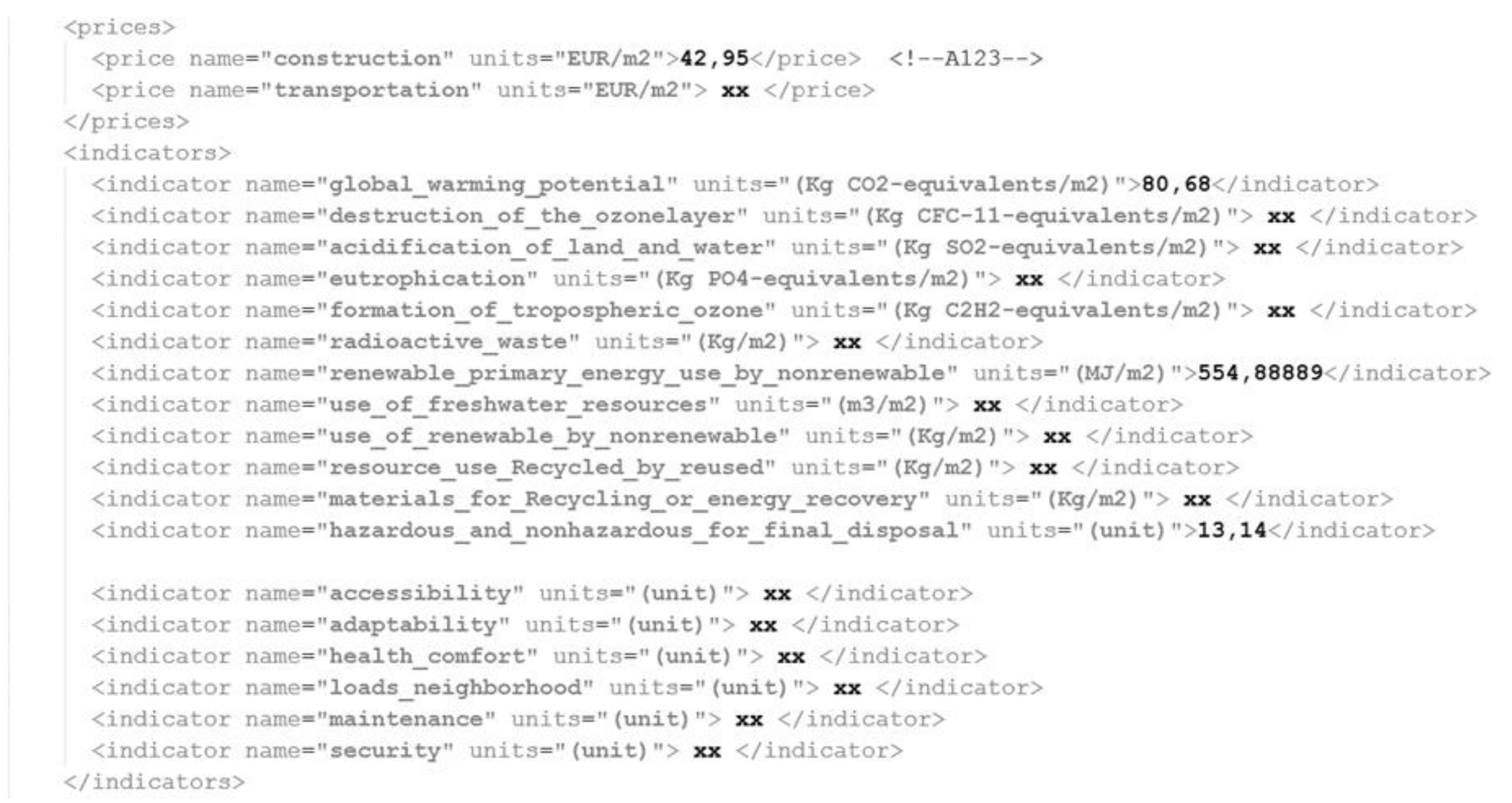
With this information—and based on the SDL model that defines the LCA of a building—the LCA could be calculated for the different scenarios. This allowed us to obtain the Pareto frontier, depending on the selected variables (see Figure 10 to review the file that contained the indicators used in the analysis). These indicators were defined formally on the SDL model and filled with the correct values using the database the modeler used on the specific project.
In Figure 11, the results obtained from NECADA for the e(CO) building are shown [50]. The Pareto frontier represented in the upper left area of the figure, allowed us to determine the best fit among all the possible alternatives in the model.
Detailed results obtained on the (e)CO project can be found in [40]. Thanks to this holistic solution, the e(CO) building LCA can be improved in its design phase. NECADA simplified the interaction of the non-specialists in the simulation user-group with an SDL model that only needed to parametrize the different factors that must be introduced in each experiment.
Through the use of SDL, we could go further in our analysis. During the use of the building, we could take advantage of the different sensors the houses currently had, from the real-time analysis of energy consumption to the possibility of controlling the windows. Since a model that defines the optimum solution for an LCA is mainly focused on the planning phase, some deviations and corrections must be performed during the use phase of the building. Here, a Smart Home connected through SDL can achieve its full potential.
5.2. A Smart House Connected through SDL and IoT
In the “use” phase (Figure 3), we focused on how people were using the houses and how energy was managed. A Smart Home is usually seen as a house where almost everything can be controlled, including the windows, doors, temperature, etc. The concept of smart home was connected through the Cradle to Cradle metaphor to the sustainability concept. The interconnection of different hardware and software used to control a house makes it difficult to easily extend and reuse the solutions. Plenty of different alternatives currently exist, some of them based on standards like KNX [51,52], standardized on EN 50090, ISO/IEC 14543, or BACnet [53], an ASHRAE, ANSI, and ISO 16484-5 standard protocol, as well as others used as de facto standards like Modbus, a serial communications protocol originally published by Modicon (now Schneider Electric) in 1979 for use with its programmable logic controllers (PLCs). There are also many other alternatives like LonWorks, Home automation, BACnet, DOLLx8, EnOcean INSTEON, Z-Wave, Intelligent building, Lighting control system, OpenTherm, Room automation, Smart Environments, and Touch panel.
In this scenario, with several communication protocols interacting with several devices, the use of an abstract layer that helps in the definition and formalization of the several processes that must be considered in a smart home, or as an extension of this in a smart city, is necessary. Additionally, as shown in this paper, SDL can be used to represent the LCA of a building, becoming an interesting candidate to represent all the processes related to a building life from the planning phase to the day to day use of the different devices interacting in a home; therefore, giving information to the residents regarding the deviations detected from the original planning. For a detailed description of the proposed use of SDL in the frame of IoT, [54] can be consulted.
6. Discussion
The proposed methodology has been successfully used in several projects. To design a double active façade [55], we used the model (in combination with Computational Fluid Dynamics (CFD) models) in a co-simulation approach. In the European project MARIE [56,57,58], we used the model to perform a double analysis for the residential typologies in the Mediterranean area, first by optimizing the comfort and economic criteria based on passive measures and, second, by a cost-effective analysis selecting active energy efficiency measures. Other projects where this model has been used include the ACE project described in [59], where the model was used to simulate the behavior of the different typologies that were later implemented in the project.
The model, using different calculus engines, allowed the optimization of the analyzed system following the European normative CEN/TC 350 (UNE-EN 15643-2, UNE-EN 15643-3, UNE-EN 15643-4). The co-simulation approach made it possible to change the calculus engine to be used, for example, in the MARIE project, we used Trnsys® [60] while in others we used Energy+ [45]. Hence, the model could be used for normative purposes and to obtain green certification for new or refurbished buildings.
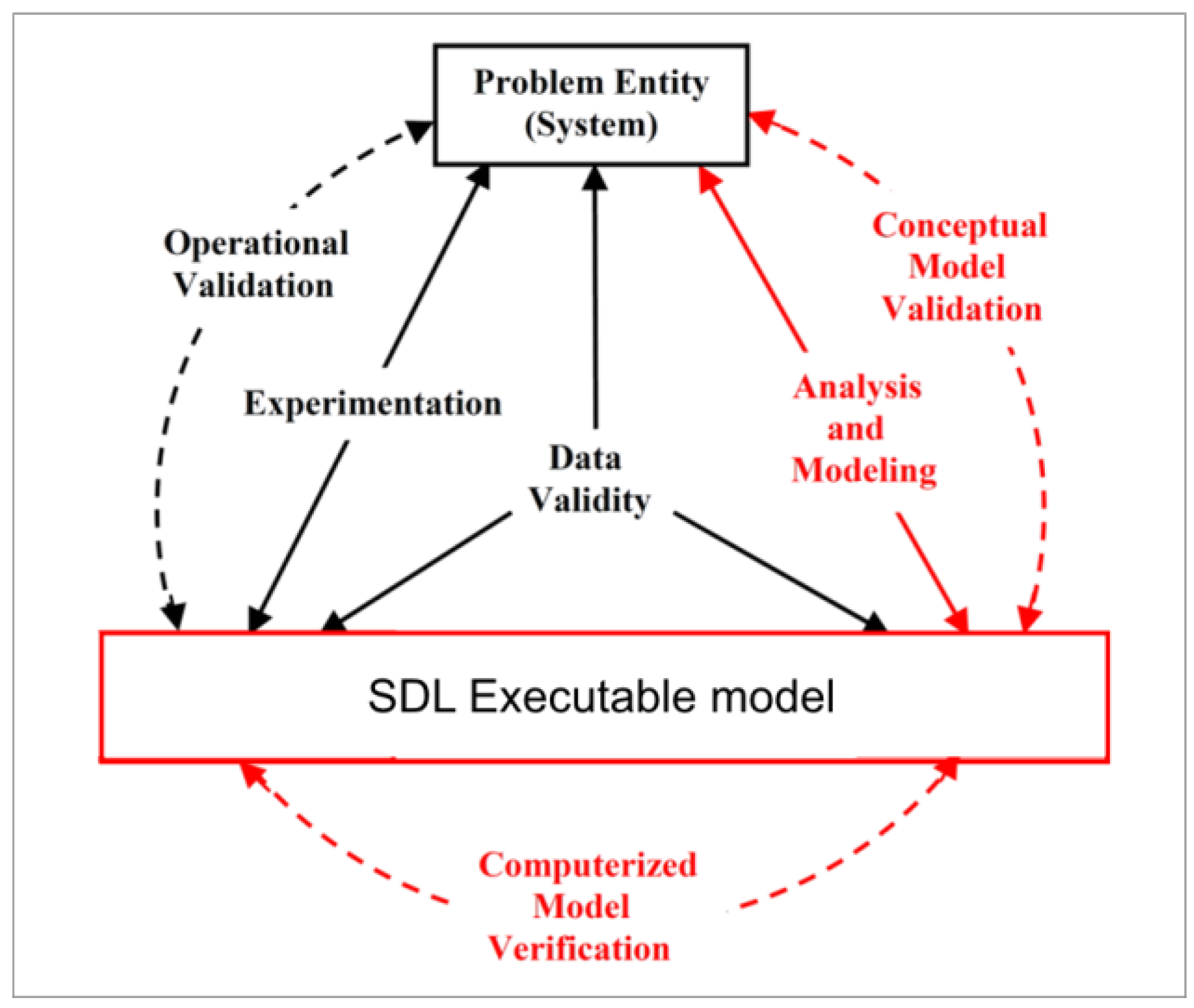
The proposed methodology allowed us to define the model using a holistic approach and simplify the interaction between the different specialists. By using an infrastructure that understood this formal language, no specific implementation was performed on the projects, thus simplifying the verification process required for the simulation projects. The steps depicted in red in the simplified version of the modeling process presented by [41], are those that are improved, see Figure 12.
7. Conclusions
In this paper, the use of SDL to represent the LCA of a building holistically was introduced. We presented how this methodology simplified the validation and verification problems related to this type of complex model. It was also shown that the implementation of these models could be achieved using a desktop program that implemented SDL models (in our case SDLPS) and a cloud infrastructure that used SDLPS as a simulation server to offer a cloud solution. This cloud solution simplified the parametrization process of a building. The use of a standard language, such as SDL, simplified implementation; as several other tools understand SDL, as mentioned in [61,62,63], among many others, this made the definition of the model and the final implementation independent of the chosen infrastructure.
Model validation was performed with the SDL representation of the model, so that all project members involved could participate in the validation process. Verification was assured as the tool recognizes SDL diagrams; however, other validation techniques could also be applied (black box, white box, Turing test, etc.).
From the perspective of the language proposed (one can select to follow this methodology with other formal languages like DEVS or PetriNets among others), SDL could be used not only to model the LCA of a building, but could naturally also represent the existing communications between the different sensors available in a building [54]. This can complete the vision of the building allowing models to be used not only at design phase, but also in the operative phase, thus becoming a virtual advisor for a house or urban area.
Author Contributions
Pau Fonseca i Casas and Antoni Fonseca i Casas conceived the use of SDL in this study and adapted, designed, and implemented the methodology and the tools described here. The work was based on a simulator named SDLPS, developed initially by Pau in his Ph.D., that executed the model developed in Antoni’s Ph.D.
Conflicts of Interest
The authors declare no conflict of interest.
Abbreviations
The following abbreviations are used in this manuscript:
| ANSI | American National Standards Institute |
| ASHRAE | American Society of Heating, Refrigerating, and Air-Conditioning Engineer |
| BRGF | Biblioteca Sector Gabriel Ferraté |
| (e)CO | Equilibrium through Cooperation |
| ISO | International Organization for Standardization |
| LCA | Life Cycle Assesment |
| SDL | Specification and Description Language |
References
- IEA. Energy Efficiency Market Report; IEA: Paris, France, 2014. [Google Scholar]
- ICER. Energy Efficiency Potential in the U.S.: 2012 through 2035. Available online: http://www.icer-regulators.net/portal/page/portal/ICER_HOME/publications_press/ICER_Chronicle/Art2_10a.html (accessed on 2 May 2017).
- Van der Grintern, B. Cradle to Cradle in a Nutshell. 2008. Available online: http://www.bluehaired.com/corner/wp-content/uploads/2009/12/Cradle-to-Cradle-in-a-nutshell-Bram-van-der-Grinten-2008.pdf (accessed on 2 May 2017).
- Rønning, A.; Brekke, A. Life cycle assessment (LCA) of the building sector: Strengths and weaknesses. In Eco-Efficient Construction and Building Materials; Woodhead Publishing: Sawston, UK, 2014; pp. 63–83. [Google Scholar]
- Hollberg, A.; Ruth, J. LCA in architectural design—A parametric approach. Int. J. Life Cycle Assess. 2016, 21, 943–960. [Google Scholar] [CrossRef]
- Means, P.; Guggemos, A. Framework for Life Cycle Assessment (LCA) Based Environmental Decision Making During the Conceptual Design Phase for Commercial Buildings. Proced. Eng. 2015, 118, 802–812. [Google Scholar] [CrossRef]
- Vilches, A.; Garcia-Martinez, A.; Sanchez-Montañes, B. Life cycle assessment (LCA) of building refurbishment: A literature review. Energy Build. 2016, 135, 286–301. [Google Scholar] [CrossRef]
- Anand, C.; Amor, B. Recent developments, future challenges and new research directions in LCA of buildings: A critical review. Renew. Sustain. Energy Rev. 2017, 67, 408–416. [Google Scholar] [CrossRef]
- BPIE. Principles for Nearly Zero-Energy Buildings. Paving the Way for Effective Implementation of Policy Requirements; Buildings Performance Institute Europe: Brussels, Belguim, 2011. [Google Scholar]
- Salom, J.; Widén, J.; Candanedo, J.; Sartori, I.; Voss, K.; Marszal, A. Understanding net zero energy buildings: Evaluation of load matching and grid interaction indicators. In Proceedings of the Building Simulation 2011: 12th Conference of International Building Performance Simulation Association, Sydney, Australia, 14–16 November 2011. [Google Scholar]
- Sartori, I.; Napolitano, A.; Voss, K. Net zero energy buildings: A consistent definition framework. Energy Build. 2012, 48, 220–232. [Google Scholar] [CrossRef]
- Salom, J.; Cubí, E.; Sánchez, A. Busando una definición concreta para un objetivo amplio. CIC Arquitectura y Construcción 2011, 485, 54–57. [Google Scholar]
- Salom, J.; Cubí, E.; Sartori, I. Edificio de energía cero: Definiciones e interacción con las redes energéticas. In Libro de Comunicaciones I Congreso EECN; EECN: Madrid, Spain, 2012. [Google Scholar]
- Llera-Sastresa, E.; Scarpellini, S.; Rivera-Torres, P.; Aranda, J.; Zabalza-Bribián, I.; Aranda-Usón, A. Energy Vulnerability Composite Index in Social Housing, from a Household Energy Poverty Perspective. Sustainability 2017, 9, 691. [Google Scholar] [CrossRef]
- EeBGuide. The EeBGuide Project. Operational Guidance for Life Cycle Assessment Studies of the Energy Efficient Buildings Initiative; Fraunhofer-Gesellschaft: Munich, Germany, 2013. [Google Scholar]
- SUDOE. EnerBuiLCA. 2012. Available online: http://4.interreg-sudoe.eu/contenido-dinamico/libreria-ficheros/8656A5AF-B808-1CEB-5C83-37836BB24FAA.pdf (accessed on 7 June 2017).
- CEN/TC 350. Sustainability of Construction Works; European Committee for Standardization: Brussels, Beguim, 2012. [Google Scholar]
- Laëtitia, A.; Olivier, B.; Pascal, R.; Daniel, Q.; Pascal, R. A simple method to consider energy balance in the architectural design of residential buildings. In Proceedings of the Symposium on Simulation for Architecture and Urban Design, Boston, MA, USA, 3–7 April 2011; pp. 115–122. [Google Scholar]
- Sattrup, P.A.; Strømann-Andersen, J.B. A methodological study of environmental simulation in architecture and engineering: Integrating daylight and thermal performance across the urban and building scales. In Proceedings of the 2011 Symposium on Simulation for Architecture and Urban Design, Boston, MA, USA, 3–7 April 2011; Attar, R., Ed.; Society for Computer Simulation International: San Diego, CA, USA, 2011; pp. 115–123. [Google Scholar]
- Sodja, A.; Zupančič, B. Modelling thermal processes in buildings using an object-oriented approach and Modelica. Simul. Model. Pract. Theory 2009, 17, 1143–1159. [Google Scholar] [CrossRef]
- Counsell, J.M.; Khalid, Y.A.; Brindley, J. Controllability of buildings: A multi-input multi-output stability assessment method for buildings with slow acting heating systems. Simul. Model. Pract. Theory 2011, 19, 1185–1200. [Google Scholar] [CrossRef]
- Liu, B.; Duan, S. Energy efficiency evaluation of building integrated photovoltaic systems with different power configurations. Simul. Model. Pract. Theory 2012, 29, 93–108. [Google Scholar] [CrossRef]
- Bruno, M.; Henderson, K.; Kim, H. Multi-objective optimization in urban design. In Proceedings of the 2011 Symposium on Simulation for Architecture and Urban Design, Boston, MA, USA, 3–7 April 2011; Attar, R., Ed.; Society for Computer Simulation International: San Diego, CA, USA, 2011; pp. 102–109. [Google Scholar]
- Zeigler, B.P.; Praehofer, H.; Kim, T.G. Theory of Modeling and Simulation Handbook of Simulator-Based Training Creating Computer Simulation Systems: An Introduction to the High Level Architecture; Academic Press: Waltham, MA, USA, 2000. [Google Scholar]
- ITU-T. Specification and Description Language—Overview of SDL-2010; ITU: Geneva, Switzerland, 2011. [Google Scholar]
- Doldi, L. SDL Illustrated—Visually Design Executable Models; TMSO Multimedia: Toulouse, France, 2001. [Google Scholar]
- Cabasino, M.P.; Giua, A.; Seatzu, C. Introduction to Petri Nets. Lect. Notes Control Inf. Sci. 2013, 433, 191–211. [Google Scholar]
- Ahmed, A.S.; Wainer, G.; Mahmoud, S. Integrating building information modeling & cell-DEVS simulation. In Proceedings of the 2010 Spring Simululation Multiconference, Orlando, FL, USA, 11–15 April 2010; Society for Computer Simulation International: San Diego, CA, USA, 2001. [Google Scholar] [CrossRef]
- Trčka, M.; Hensen, J.L.M.; Wetter, M. Co-simulation for performance prediction of integrated building and HVAC systems—An analysis of solution characteristics using a two-body system. Simul. Model. Pract. Theory 2010, 18, 957–970. [Google Scholar] [CrossRef]
- Stahl, I.; Born, R.G.; Henriksen, J.O.; Herper, H. GPSS 50 years old, but still young. In Proceedings of the 2011 Winter Simulation Conference, Phoenix, AZ, USA, 11–14 December 2011; pp. 3947–3957. [Google Scholar]
- O’Reilly, J.J. Optimization test problems with uniformly distributed coefficients. In Proceedings of the 1991 Winter Simulation Conference, Phoenix, AZ, USA, 8–11 December 1991. [Google Scholar]
- Jones, J. SIMPROCESS III: Object-oriented business process simulation. In Proceedings of the 1995 Winter Simulation Conference, Arlington, VA, USA, 3–6 December 1995. [Google Scholar]
- Altiok, T.; Melamed, B. Simulation Modeling and Analysis with ARENA; Academic Press: Waltham, MA, USA, 2007. [Google Scholar]
- Pegden, C.D.; Sturrock, D.T. Introduction to Simio. In Proceedings of the 2011 Winter Simulation Conference, Phoenix, AZ, USA, 11–14 December 2011; pp. 29–38. [Google Scholar]
- Concepcion, A.I.; Zeigler, B.P. DEVS formalism: A framework for hierarchical model development. IEEE Trans. Softw. Eng. 1988, 14, 228–241. [Google Scholar] [CrossRef]
- Vangheluwe, H.L.M. DEVS as a common denominator for multi-formalism hybrid systems modelling. In Proceedings of the IEEE International Symposium on Computer-Aided Control System Design (Cat. No.00TH8537), Anchorage, AK, USA, 25–27 September 2000; IEEE: New York, NY, USA, 2000; pp. 129–134. [Google Scholar]
- Shang, H.; Wainer, G. A Simulation Algorithm for Dynamic Structure DEVS Modeling. In Proceedings of the 2006 Winter Simulation Conference, Monterey, CA, USA, 3–6 December 2006; pp. 815–822. [Google Scholar]
- Goldstein, R.; Khan, A.; East, K.S. Development of discrete event system specification (DEVS) building performance models for building energy design. In Proceedings of the Symposium on Simulation for Architecture & Urban Design, San Diego, CA, USA, 7–10 April 2013. [Google Scholar]
- Gotzhein, R.; Krämer, M.; Litz, L.; Chamaken, A. Energy-aware system design with SDL. In Lecture Notes in Computer Science (Including Subseries Lecture Notes in Artificial Intelligence and Lecture Notes in Bioinformatics); Springer: Berlin, Germany, 2009; pp. 19–33. [Google Scholar]
- Fonseca i Casas, P.; Fonseca i Casas, A.; Garrido-Soriano, N.; Casanovas, J. Formal simulation model to optimize building sustainability. Adv. Eng. Softw. 2014, 69, 62–74. [Google Scholar] [CrossRef]
- Sargent, R. Verification and validation of simulation models. In Proceedings of the 2009 Winter Simulation Conference, Austin, TX, USA, 13–16 December 2009; Rossetti, M.D., Hill, R.R., Johansson, B., Dunkin, A., Ingalls, R.G., Eds.; IEEE: New York, NY, USA, 2009; pp. 162–176. [Google Scholar]
- Alfaro Garrido, L.; Lucas Masero, J.; Díez Bernabé, G. New tool to identify environmental impacts on the construction. In Proceedings of the VII Congreso Europeo sobre Eficiencia Energética y Sostenibilidad en Arquitectura y Urbanismo, San Sebastian, Spain, 4–6 July 2016. [Google Scholar]
- AEN/CTN. Evaluación de la Sostenibilidad en los Edificios. Parte 4: Marco para la Evaluación del Comportamiento Económico; UNE-EN 15643-4:2012; AENOR: Madrid, Spain, 2012. [Google Scholar]
- Baayen, H. Eco-indicator 99 Manual for Designers; Ministry of Housing, Spatial Planning and the Environment: The Hague, The Netherlands, 2000.
- EnergyPlus. Input Output Reference the Encyclopedic Reference to EnergyPlus Input and Output; U.S. Department of Energy: Washington, DC, USA, 2014.
- Fonseca i Casas, P.; Fonseca i Casas, A.; Garrido-Soriano, N.; Ortiz, J.; Casanovas, J.; Salom, J. Optimal Buildings’ Energy Consumption Calculus through a Distributed Experiment Execution. Math. Probl. Eng. 2015, 2015, 1–12. [Google Scholar] [CrossRef]
- Fonseca i Casas, P. SDL distributed simulator. In Proceedings of the 2008 Winter Simulation Conference, Miami, FL, USA, 7–10 December 2008. [Google Scholar]
- Fonseca i Casas, P.; Pi Palomés, X.; Casanovas Garcia, J.; Jové, J. Definition of Virtual Reality Simulation Models Using Specification and Description Language Diagrams; Khendek, F., Toeroe, M., Gherbi, A., Reed, R., Eds.; Lecture Notes in Computer Science; Springer: Berlin, Germany, 2013. [Google Scholar]
- Smith, M. BIM in Construction. Available online: http://www.thenbs.com/topics/BIM/articles/bimInConstruction.asp (accessed on 7 June 2017).
- Fonseca i Casas, A.; Fonseca i Casas, P.; Colls, M. In NZEB. Optimización mediante co-simulación. Estudio de caso (e)Co, proyecto prototipo del concurso Solar Decathlon 2012. In Proceedings of the CONAMA 2012 Congreso Nacional de Medio Ambiente, Madrid, Spain, 26–30 November 2012. [Google Scholar]
- KNX Association. KNX System Specifications—Architecture; KNX Association: Brussels, Belguim, 2013. [Google Scholar]
- KNX Association. System Specifications; KNX Association: Brussels, Belguim, 2014. [Google Scholar]
- ISO. Building Automation and Control Systems (BACS)—Part 1: Project Specification And Implementation; ISO: Geneva, Switzerland, 2010. [Google Scholar]
- Sherratt, E.; Ober, I.; Gaudin, E.; Fonseca i Casas, P.; Kristoffersen, F. SDL—The IoT language. In SDL 2015: Model-Driven Engineering for Smart Cities. Lecture Notes in Computer Science; Fischer, J., Scheidgen, M., Schieferdecker, I., Reed, R., Eds.; Springer: Cham, Switzerland, 2015. [Google Scholar]
- ACCIONA. Japan-Spain Energy Efficient Development for Ultra-Low Energy Buildings. Available online: https://www.acciona.com/sustainability/environment/environmental-innovation/systems-storing-seasonal-heat-buildings/ (accessed on 7 June 2017).
- Salom, J.; Ortiz, J. Russo, Method to develop cost-effective studies of energy efficiency measures for Mediterranean residential existing buildings with multi-criteria optimization. In Proceedings of the World Sustainable Buldings SB14, Barcelona, Spain, 28–30 October 2014. [Google Scholar]
- Ortiz, J.; Fonseca i Casas, A.; Salom, J.; Garrido Soriano, N.; Fonseca i Casas, P. Cost-effective analysis for selecting energy efficiency measures for refurbishment of residential buildings in Catalonia. Energy Build. 2016, 128, 442–457. [Google Scholar] [CrossRef]
- Ortiz, J.; Fonseca, A.; Salom, J.; Garrido, N.; Fonseca, P.; Russo, V. Comfort and economic criteria for selecting passive measures for the energy refurbishment of residential buildings in Catalonia. Energy Build. 2016, 110, 195–210. [Google Scholar] [CrossRef]
- Fonseca i Casas, A.; Fonseca i Casas, P. Casanovas, Analysis of Applications to Improve the Energy Savings in Residential Buildings Based on Systemic Quality Model. Sustainability 2016, 8, 1051–1069. [Google Scholar] [CrossRef]
- Thermal Energy System Specialists. TRNSYS Transient System Simulation Tool. Available online: http://www.trnsys.com/ (accessed on 21 March 2015).
- PragmaDev SARL. PragmaDev Studio. Available online: http://www.pragmadev.com/product/index.html (accessed on 9 January 2016).
- Cinderella ApS. Cinderella. Available online: http://www.cinderella.dk/ (accessed on 9 January 2016).
- IBM Co. Rational SDL Suite. Available online: http://www-03.ibm.com/software/products/en/ratisdlsuit (accessed on 9 January 2016).
Figure 1.
Structural view of a Specification and Description Language (SDL) System.
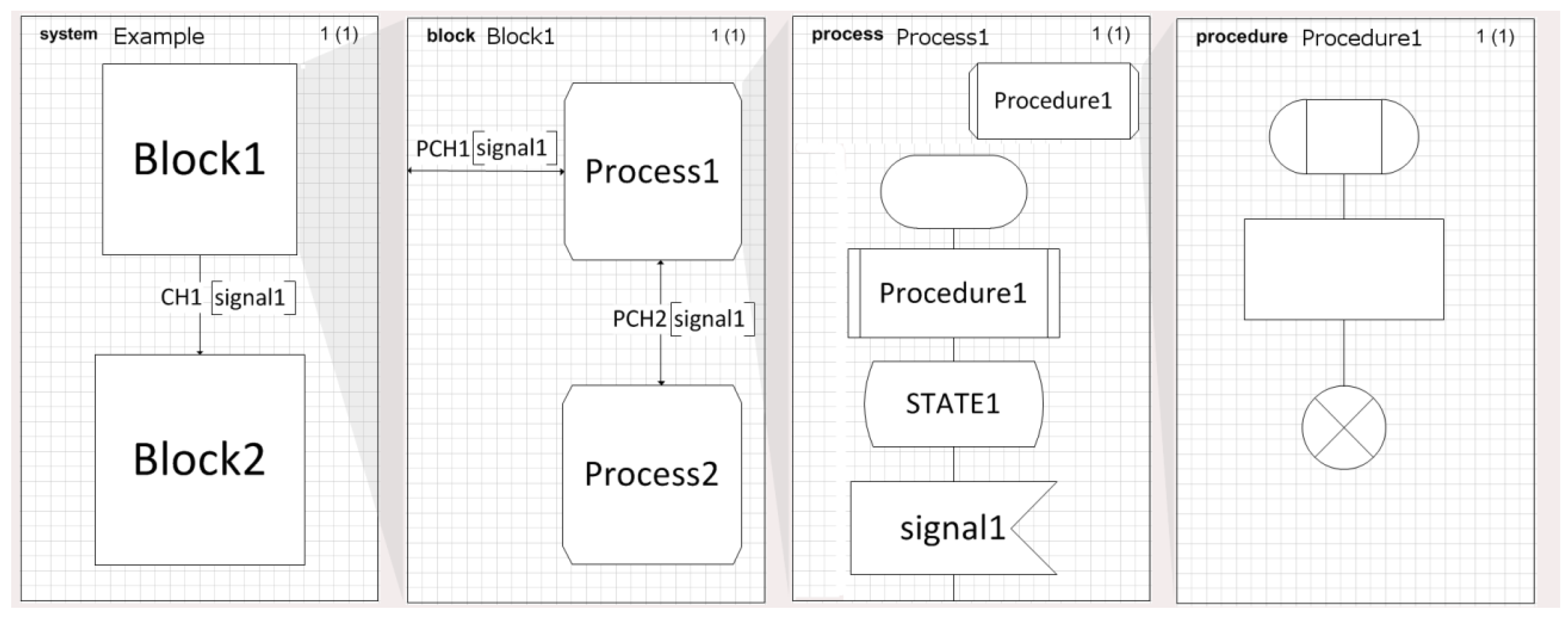
Figure 2.
SDL system diagram detailing the main components of the model considered in the study.

Figure 3.
Cradle to Cradle, see [3]. Every house (and product) from the point of view of the complete life cycle. The phases that are now included in the model are Transportation, defining a CO2 consumption for the materials; Manufacturing and Distribution, defining a CO2 consumption for the constructing solutions; and Use, detailed with the main processes of the model that represents the behavior of the buildings during this phase.
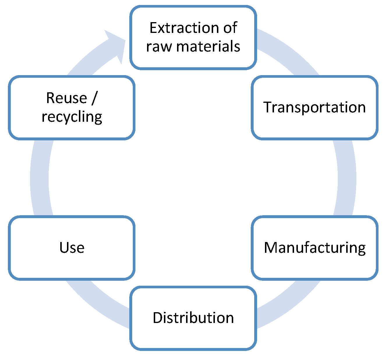
Figure 4.
Behavior of the building in the DESIGNED state.

Figure 5.
This figure details the S1_ACV_Materials and S1_ConstructionProcess.

Figure 6.
SDLPS interface with the building model.

Figure 7.
NECADA cloud solution login screen.

Figure 8.
Public projects shown on the NECADA website include the BRGF, MARIE, and (e)CO projects. By using NECADA, the users do not interact directly with the SDL model, but with the factors (declarations) used inside the model to parametrize the different experiments.
Figure 8.
Public projects shown on the NECADA website include the BRGF, MARIE, and (e)CO projects. By using NECADA, the users do not interact directly with the SDL model, but with the factors (declarations) used inside the model to parametrize the different experiments.

Figure 9.
File containing the permutations to be executed and those defined in the experimental design.
Figure 9.
File containing the permutations to be executed and those defined in the experimental design.

Figure 10.
Indicators to be used on the calculus of the LCA; not all the indicators are used in this specific example.
Figure 10.
Indicators to be used on the calculus of the LCA; not all the indicators are used in this specific example.

Figure 11.
Results from the analysis of the different scenario for the e(CO) building. On top are shown the Pareto frontiers for the more than 4000 different parametrizations analyzed, on the bottom is a sensitivity analysis obtained from a detailed analysis of all the obtained information. This helps in the determination of optimal actions to save energy using the passive elements in the building.
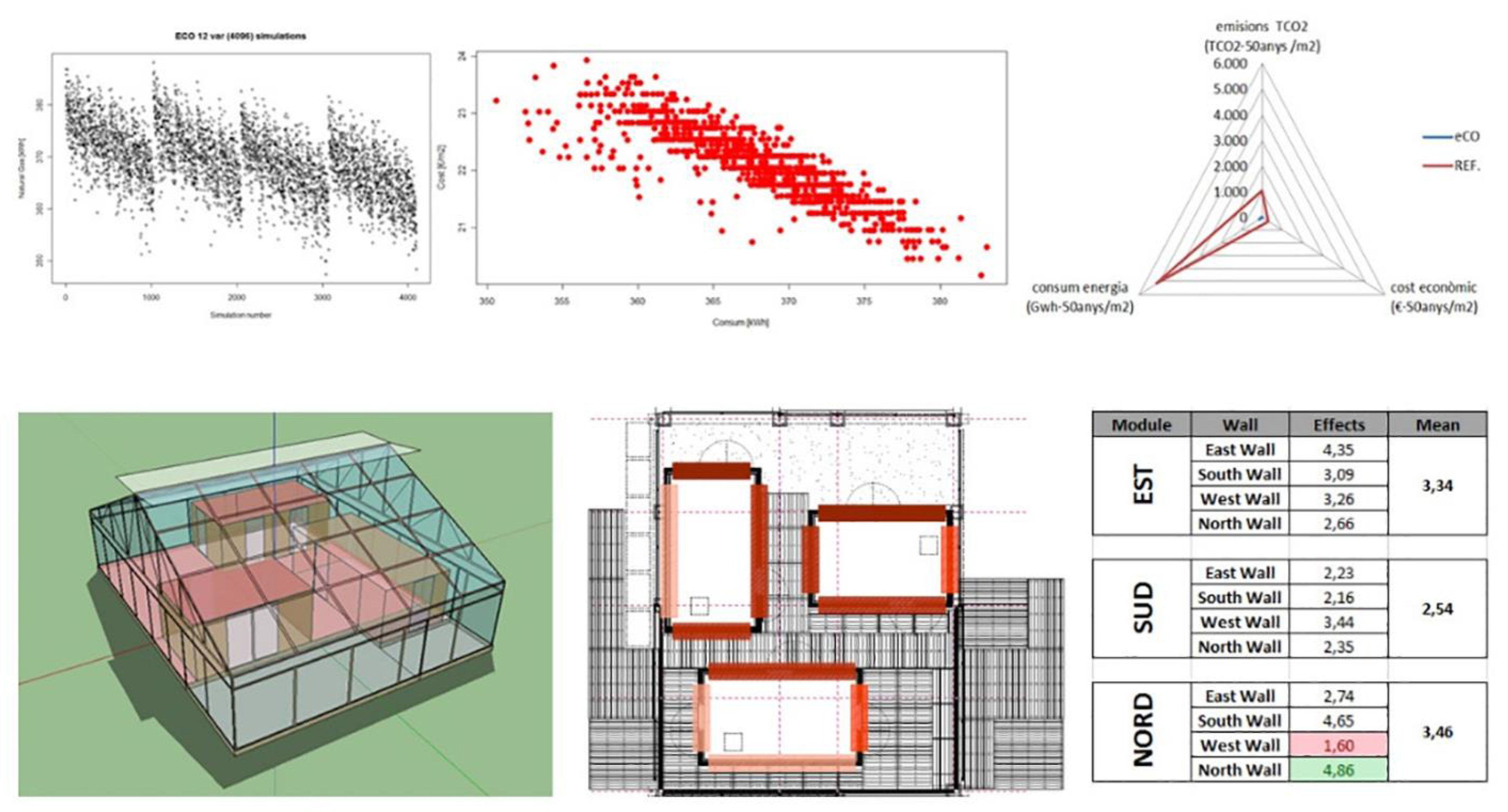
Figure 12.
Simplified version of the modeling process, based on [41]. The SDL executable model can be validated by all team members; furthermore, the automatic implementation assures its verifiability.
Figure 12.
Simplified version of the modeling process, based on [41]. The SDL executable model can be validated by all team members; furthermore, the automatic implementation assures its verifiability.


Table 1.
Main input model variables.
| Variable | Description |
|---|---|
| *.epw file (climate file) | This file contains the description of the climate that affects the building. In this case, the building is located in Madrid, Spain. |
| *.idf file (model file) | This file contains the structure of the building (geometry, materials, etc.). |
| Materials and constructing solutions database | Needed for the calculations and is obtained using a dedicated database or connected to external databases like the one provided by the ITeC [42]. |
Table 2.
Main output variables.
| Variable | Description |
|---|---|
| Energy Impact | The energy demand of the model will be determined to minimize the building’s energy (energy for heating and cooling). |
| Environmental Impact | Analysis of the environmental impact of materials used (Global Warming, Ozone Depletion, etc.) according to an LCA (Life Cycle Assesment). |
| Economic Impact | Analysis of the economic costs of the LCA process, the materials used in construction, and the energy and material demand of the prototype (described in the standard prEN 15643-4 [43]). |
| Social Impact | Analysis of the social impacts of the building on its immediate environment (impacts can be positive or negative) |
© 2017 by the authors. Licensee MDPI, Basel, Switzerland. This article is an open access article distributed under the terms and conditions of the Creative Commons Attribution (CC BY) license (http://creativecommons.org/licenses/by/4.0/).
Share and Cite
MDPI and ACS Style
Fonseca i Casas, P.; Fonseca i Casas, A. Using Specification and Description Language for Life Cycle Assesment in Buildings. Sustainability 2017, 9, 1004. https://doi.org/10.3390/su9061004
AMA Style
Fonseca i Casas P, Fonseca i Casas A. Using Specification and Description Language for Life Cycle Assesment in Buildings. Sustainability. 2017; 9(6):1004. https://doi.org/10.3390/su9061004
Chicago/Turabian StyleFonseca i Casas, Pau, and Antoni Fonseca i Casas. 2017. "Using Specification and Description Language for Life Cycle Assesment in Buildings" Sustainability 9, no. 6: 1004. https://doi.org/10.3390/su9061004
Note that from the first issue of 2016, this journal uses article numbers instead of page numbers. See further details here.